

Page 1

Instructions for Use
Leica LN22 – Liquid Nitrogen Freezing Device
V1.2, English – 10/2012
Order No.: 14 0373 80101 RevB
Always keep this manual near the instrument.
Read carefully prior to operating the instrument.
Leica LN22
Liquid nitrogen freezing
device
Page 2

Page 3

NOTE
The information contained in this documentation
represents the state of the art in science and
technology.
We are under no obligation to update the present
manual periodically and on an ongoing basis according to the latest technical developments, nor
to provide our customers with additional copies,
updates etc. of this manual.
For erroneous statements, drawings, technical
illustrations etc. contained in this manual we exclude liability as far as permissible according to
the national law applicable in each individual
case. In particular, no liability whatsoever is accepted for any financial loss or consequential
damage caused by or related to compliance with
statements or other information in this
manual.
Statements, drawings, illustrations and other information as regards contents or technical details of the present manual are not to be considered as warranted characteristics of our
products.
These are determined only by the contract provisions agreed between ourselves and our customers.
Leica reserves the right to change technical
specifications as well as manufacturing processes without prior notice. Only in this way is it possible to continuously improve the technology and
manufacturing techniques used in our products.
This document is protected under copyright
laws. Any copyrights of this document are retained by Leica Biosystems Nussloch GmbH.
Any reproduction of text and illustrations (or of
any parts thereof) by means of print, photocopy,
microfiche, web cam or other methods – including any electronic systems and media – requires
express prior permission in writing by Leica
Biosystems Nussloch GmbH.
© Leica Biosystems Nussloch GmbH
Published by:
Leica Biosystems Nussloch GmbH
Heidelberger Strasse 17 - 19
D-69226 Nussloch
Germany
Telephone: +49 (0) 62 24 143-0
Fax: +49 (0) 6224 143-2 68
Internet: http://www.LeicaBiosystems.com
Leica LN22
3
Page 4

Table of contents
1. Important information ................................................................................................................ 6
1.1 Symbols in the text and their meanings ................................................................................... 6
1.2 Intended use of instrument ........................................................................................................ 6
2. Safety ............................................................................................................................................ 7
2.1 Safety instructions ...................................................................................................................... 7
3. Instrument components and specifications ....................................................................... 15
3.1 Technical data ............................................................................................................................ 15
3.2 Overview and instrument components .................................................................................. 16
3.3 Standard delivery ...................................................................................................................... 17
4. Startup ........................................................................................................................................ 18
4.1 Installation site requirements.................................................................................................. 18
4.2 Unpacking ................................................................................................................................... 18
4.3 Preparing the microtome for attachment of the LN22 ......................................................... 19
4.4 Installing the cryochamber ...................................................................................................... 20
4.5 Connecting to mains ................................................................................................................. 21
4.5.1 Checking the voltage selector setting ................................................................................... 21
4.5.2 Changing the voltage selector setting and inserting the fuses ......................................... 22
4.5.3 Plugging in the connection cables ......................................................................................... 23
4.5.4 Grounding the Dewar ................................................................................................................ 23
4.5.5 Connecting the mains cable .................................................................................................... 24
4.6 Switching on the instrument.................................................................................................... 24
4.7 Control unit ................................................................................................................................. 25
4.8 Specimen holders...................................................................................................................... 27
4.8.1 Specimen holder for block embeddings ................................................................................ 27
4.8.2 Universal specimen holder and flat specimen holder ......................................................... 29
4.9 Knife holders .............................................................................................................................. 30
4.9.1 Knife holders for tungsten carbide knives............................................................................. 30
4.9.2 Glass knife, CryoDiamond knife, trimming knife Histo ......................................................... 30
4.10 Preparing the pumping system ............................................................................................... 33
4.11 Refrigerating .............................................................................................................................. 33
4.12 Refilling the Dewar vessel ....................................................................................................... 34
4.13 Heating up the chamber ........................................................................................................... 35
4
Instructions for Use V1.2, RevB – 10/2012
Page 5

Table of contents
5. Cleaning and maintenance .................................................................................................... 36
5.1 Cleaning ...................................................................................................................................... 36
5.2 Maintenance .............................................................................................................................. 39
5.2.1 General maintenance instructions ......................................................................................... 39
5.2.2 Exchanging the mains fuses .................................................................................................... 39
5.2.3 Exchanging the bulb .................................................................................................................. 40
5.2.4 Removal of the pump valves .................................................................................................... 41
6. Appendix .................................................................................................................................... 42
6.1 Ordering information ................................................................................................................. 42
7. Warranty and service .............................................................................................................. 43
Leica LN22
5
Page 6
1. Important information
1.1 Symbols in the text and their meanings
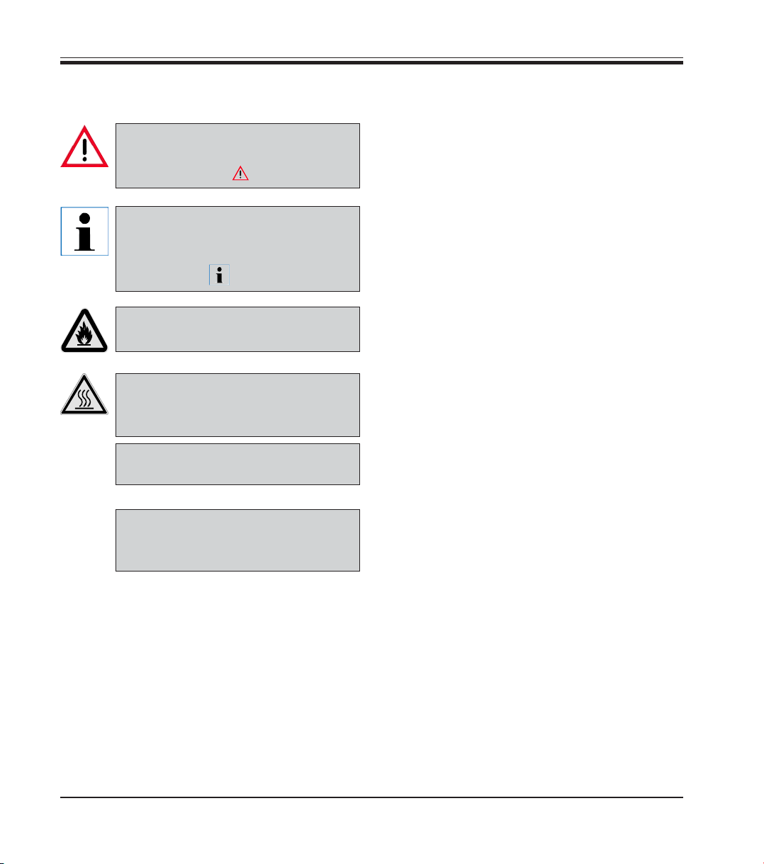
Warnings
appear in a gray box and are marked by
a warning triangle .
Notes,
i.e. important user information, appear in
a gray box and are marked by an infor-
mation symbol .
Solvents and reagents that are flammable are identified by this symbol.
This warning symbol identifies surfaces
of the instrument that are hot during operation.
(5)
Numbers in parentheses refer to item
numbers in illustrations.
1.2 Intended use of instrument
The Leica LN22 is a liquid nitrogen freezing device to quickly and effortlessly change from sectioning at room temperature to freezing sectioning applications and vice versa.
Any other use of the instrument is
considered improper!
ENTER
6
Function keys that must be pressed on the
input screen are boldfaced in the text and
capitalized.
Instructions for Use V1.2, RevB – 10/2012
Page 7
Be sure to comply with the safety instructions and warnings provided in this chapter.
Be sure to read these instructions, even if you are already familiar with the operation and use
of other Leica products.
2.1 Safety instructions
2. Safety
These operating instructions contain important
information for the operational safety and maintenance of the device and are an important component of the device.
If additional requirements on accident
prevention and environmental protection exist in the country of operation,
this Instructions for Use must be supplemented by appropriate instructions
to ensure compliance with such requirements.
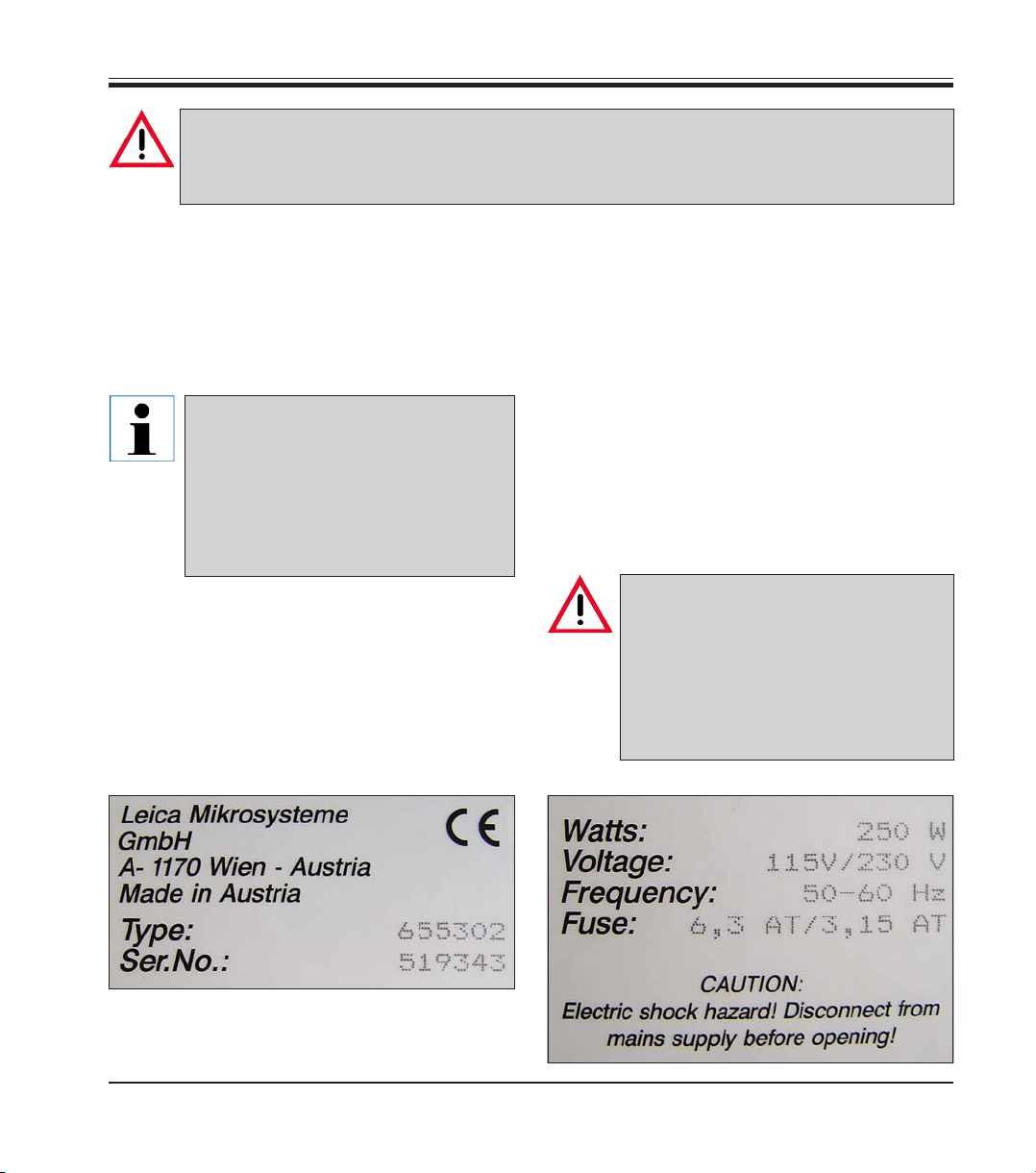
Device type
All information provided in this manual applies
only to the instrument type indicated on the cover
page.
An identification label with the serial number is
attached on the underside
of the control unit.
This instrument was built and tested in accordance with the safety regulations for electrical
measuring, control, regulating and laboratory
devices as specified below:
• EN 61010-1:2001,
• EN 61326: 1997+A1: 1998 +A2: 2001
.
The protective devices on both instrument and accessories must neither be
removed nor modified.
Only service personnel qualified by
Leica may repair the instrument and
access the instrument’s internal components.
Leica LN22
7
Page 8

2. Safety
Safety measures in cryopreparation
Provided that the safety measures outlined in the present chapter are
observed, using all safety devices of the instrument as described, there
is no significant accident risk involved in cryopreparation. For this reason, please make sure at all times when working with the LN22 system
that the few, but decisive, rules for safety listed in this chapter are followed.
When handling liquid nitrogen (LN
•LN2 is extremely cold and boils at -196°C. As a consequence, also nitrogen gas (GN2) escapes from boiling LN2 at a very low temperature.
Bear in mind, that LN2 and/or GN2 as well as objects which are in contact with LN2 / GN2 (pipe joints, valves, pipes, containers or stoppers)
can cause severe frost bite on skin and eyes.
• When evaporating, LN2 expands at a ratio of approximately 1 : 700,
i.e. 1 liter of liquid nitrogen produces almost 1 m3 of nitrogen gas
(GN2). Therefore, please make sure that the working area is kept well
ventilated when larger quantities of liquid nitrogen evaporate (e.g.
when pouring LN2 from one container into another). LN2 residues from
containers may only be emptied outdoors: Useful for disposing of liquid nitrogen is a gravel-filled container or pit, where LN2 will evaporate quickly and safely.
• Nitrogen gas (GN2) is odorless and has no taste so it cannot be distinguished from normal air when inhaled. GN2 is nontoxic as a substance. Still, a higher GN2 content (normal ratio: about 78 % GN2 to
21 % of oxygen) in the air will cause the oxygen level to diminish, thus
causing sudden fainting and deep unconsciousness without any preceding warning symptoms (such as numbness, dizziness).
In case of doubt about the oxygen level in the air it is advisable to use
a gas analyzer with an oxygen level indication range of 0 to 25 %.
There is danger when the oxygen level drops below 18 %.
), please bear in mind the following:
2
8
Instructions for Use V1.2, RevB – 10/2012
Page 9

2. Safety
If an unconscious person remains in such a low-oxygen environment,
death may occur.
In case of emergency immediately call a physician and an ambulance. If breathing stops, apply artificial respiration at once.
• For the reasons just explained, never place LN2 containers in closed
storage rooms. Due to defects because of improper handling (jolts,
mechanical damage) or simply by normal wear, the evaporation rate
of Dewar vessels may rise to several liters per day. In enclosed
spaces, this will cause a dangerous reduction of the oxygen level in
the air.
• Please remember that the LN22 system evaporates 2 to 3 liters of liq-
uid nitrogen per hour during normal operation. This quantity of liquid
corresponds to 2 to 3 m
area is kept well ventilated at all times and adhere to the precautionary measures described above.
• Be extremely careful when bringing objects at ambient temperature
into contact with LN
of gas will form around the object. This makes any significant transfer
of warmth impossible and so comparatively little LN2 will evaporate.
However, as soon as the object has cooled down sufficiently there
will often occur strong boiling and splashing of LN2 at a time when it
is no longer expected.
3
of GN2/h. Therefore, make sure your work
. During the first few moments an insulating layer
2
9
Page 10
2. Safety
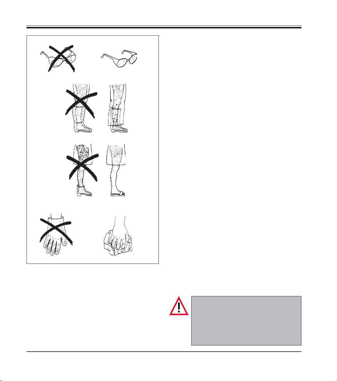
• There are clothing items and protective gear
with certain characteristics which you should
specifically avoid when working with LN2: Do
a
b
not wear closed safety goggles (a), boots (c),
shoes (e) and gloves (g) into which LN
splashes can enter, but from where they cannot escape. LN2 that has splashed into such
items will evaporate immediately inside the
item thus causing severe injuries, before the
item can be removed or taken off. Therefore,
always use safety goggles with side protec-
c
d
tion but which are open at the top and at the
bottom (b), so that LN2 splashes can escape
immediately. Wear boots only in combination
with long, loose-fitting (not tight!) pants that
fall over the boots (d) and completely cover
their upper opening. Only wear open slippers
(f) in the lab, no shoes or pumps that enclose
e
f
your feet entirely.
In combination with open slippers/sandals only
wear pants without cuffs, so that LN
will flow off freely. When pouring LN2 from one
container into another or when inserting the
Dewar pump into the Dewar, never wear safety
gloves! As an alternative to gloves you can use
an open flannel cloth (h) to protect your hands
gh
when touching cold components. Protective
gloves are useful when handling cold and dry
Fig. 1
objects, however they are not for work with LN2.
splashes
2
2
• If your skin is injured by splashing LN2, immediately rinse the affected skin area(s) thoroughly with lukewarm (body temperature!)
water. In case of serious injuries, immediately
see a dermatologist.
10
If LN2 splashes into your eyes, rinse the
eye immediately and thoroughly with
lukewarm water. If available in your lab,
use a special eye-rinsing device for that
purpose. After rinsing, immediately see
an ophthalmologist.
Instructions for Use V1.2, RevB – 10/2012
Page 11
Loosely fitted stopper
Fig. 2
2. Safety
• Once every three months check the actual evaporation rate of your
Dewar vessels and compare the measuring results to the evaporation
rates specified by the manufacturer. The evaporation rate of an undamaged metal Dewar is far less than 1 liter per day. Defective
Dewars with evaporation rates higher than that are a safety risk and
should be taken out of service or repaired.
• Standard Dewar vessels, such as the metal Dewar of the LN22 system, are not pressure vessels, therefore make sure they are closed
only with a special Dewar topper (Fig. 2). These stoppers fit loosely
onto the Dewar neck and leave a sufficiently large gap to allow for
sudden evaporation of GN2. Check the stopper frequently to make
sure it will not be stuck to the Dewar neck by ice deposits (Fig. 3).
Never close a Dewar vessel with stoppers that you have crafted
yourself (Fig. 4). Through exposure to shock or vibration (e.g. transport), a gas-tight closed Dewar vessel can release GN2 in an explosion-like fashion and burst in the process. In that case the entire LN
content (35 liters = 35m3 GN2) will evaporate at once (that may e.g.
happen inside a vehicle during transport). When a Dewar moves, thus
causing a sudden evaporation of LN
per will rise due to the gas pressure, thus opening a wide enough gap
for the GN2 to escape (Fig. 5). The small quantities of LN2 which may
escape as well in such situations do not have to be regarded as a significant safety risk.
, an appropriately designed stop-
2
2
Fig. 3
Ice deposits
Tightly fitted stopper
with seal
Fig. 4
GN
Fig. 5
2
GN
2
11
Page 12
2. Safety
• Never leave LN2 in open containers where it can exchange with the
room atmosphere. The boiling point of LN2 (-196°C) is lower than that
of liquid oxygen (-183°C). If a large LN2-surface is exposed to the air,
oxygen from the air is absorbed by the LN2 while nitrogen is released
into the air. LN2 with a high content of liquid oxygen has a bluish color.
In that case, caution is advised, since concentrated liquid oxygen is a
fire hazard.
• Make sure that your Dewar vessel is filled with no other substances
than LN2. If at the filling location also other gases are refilled, install a
warning sign there that clearly states: “Liquid nitrogen only”. Check
the color of the cryogen! Bluish color indicates a high oxygen con-
tent (see previous paragraph). If LN2 is stored during a prolonged
period of time, liquid oxygen will accumulate in the LN2 vessel, since
liquid oxygen has a higher boiling point (-183°C) than liquid LN2
(-196°C).
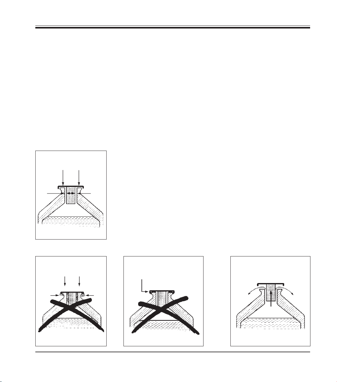
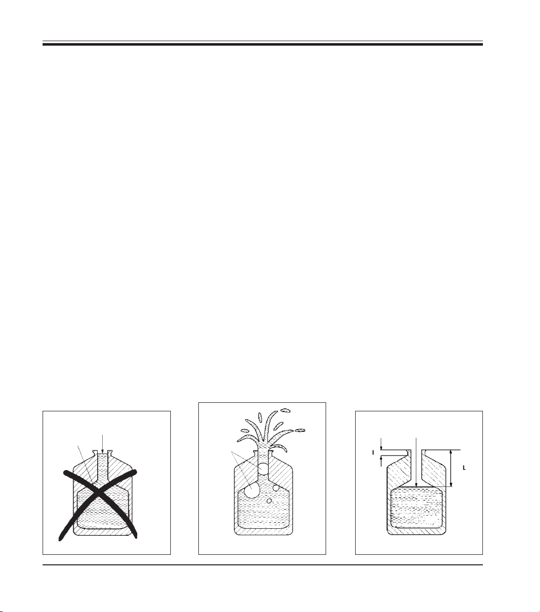
• Never fill a Dewar vessel up to the neck with LN2 (Fig. 6). In case of a
boiling delay, there is danger that the rapidly expanding gas bubbles
will force the LN
in the neck upwards causing it to splash (Fig. 7). For
2
this reason, always make sure that the LN2 surface level is below the
neck of the vessel (Fig. 8). Also bear in mind, that in most cases the
length ‘l’ of the outer insulation differs from the length ‘L’ of the actual
Dewar neck.
LN2 level
LN
2
Fig. 6 Fig. 7
12
GN
LN2 level
2
Fig. 8
Instructions for Use V1.2, RevB – 10/2012
Page 13
Warnings – Installation/Connection to mains
The room where the instrument is installed must either be well ventilated or be large enough to
avoid a dangerous decrease of the oxygen level in the air.
Please read chapter 2 ‘Safety instructions’ carefully!
Pay careful attention to chapter 3 - ‘Technical data’.
The voltage selector is preset to 230V in the factory.
Before connecting the instrument to the mains power, please check whether the factory setting
is identical with the local mains power in your lab!
The mains cable inlet is sealed with an adhesive tape that indicates the factory setting the instrument is delivered with.
Severe damage may be caused to the instrument when operating it at an incorrect voltage setting.
Do not change the voltage selector setting with the instrument being connected to the mains!
The Dewar must be externally grounded!
The instrument may only be connected to a grounded mains power outlet socket. To connect
the instrument only use one of the mains cables that are supplied together with the instrument!
2. Safety
Warnings – Maintenance
Only authorized and qualified service personnel may access the internal components of the instrument for service and repair!
Before opening the instrument, switch off the mains switch and pull the mains plug!
Before exchanging the fuses, switch off the mains switch and pull the mains plug!
When exchanging fuses, only replacement fuses with the same specification as the original
ones may be used. Refer to chapter 3 ‘Technical data’ for the correct specifications.
Before replacing the lamp, switch off the mains switch and pull the mains plug!
Leica LN22
13
Page 14
2. Safety
Warnings – working at the instrument
During operation, metal surfaces and components inside the cryochamber can reach temperatures from as low as -196°C up to as hot as +110°C!
Touching these extremely cold or hot parts can cause severe injury!
For that reason, for any type of manipulations inside the cryochamber you may use only the
special tools which come as part of the standard delivery and the use of which is described in
detail in the present manual.
Transfer of frozen specimens may also only be done by means of the corresponding special
tools.
Always attach the specimen holder before inserting the knife holder!
The light has to be on as long as the knife is inside the cryochamber!
Exercise extreme caution when handling knives! The cutting edges are extremely sharp and
can cause severe injury!
Never try to catch a falling knife!
The knife may only be inserted into the knife holder shortly before sectioning and must be removed from the knife holder directly afterwards!
Cleaning
14
To insert the knife holder into the cryochamber, always use the corresponding manipulator
(part of standard delivery)!
The knife edge is exposed! Risk of injury!
Do not use acetone or xylene to clean the lacquered surfaces of the instrument.
Instructions for Use V1.2, RevB – 10/2012
Page 15

3. Instrument components and specifications
3.1 Technical data
General
Approvals: The device-specific approval symbols are located
on the underside of the control unit next to the
identification label.
Supply voltage: 100-240V/47-63Hz
Power draw: 250W
Room temperature: up to -150°C
Temperature stability: +/-1°C
Nitrogen consumption
in standby mode: approx. 1l/day
Dimensions and weight Control unit Cryochamber
Dimensions: inside outside
Width: 250mm 120mm 253mm
Depth: 340mm 100mm 172mm
Height: 120mm 130mm 171.5mm
Weight: 8.2kg 7.9kg
Fuses
Miniature fuses (5.0 x 20mm): 220-240V: 3.15 AT
100-120V: 6.3 AT
15
Page 16

3. Instrument components and specifications
3.2 Overview and instrument components
3
4
2
6
5
1 Cryochamber
2 Control unit
3 Liquid nitrogen
pump
1
4 Dewar vessel for
liquid nitrogen on
roller base
5 Connection cable
6LN
connection
2
hose
The liquid nitrogen freezing device LN22 quickly
converts a rotary microtome into a cryosectioning
system.
The LN22 attachment consists of a cryochamber,
which encloses the sectioning area, and which
is refrigerated by a permanent flow of liquid nitrogen, pumped from a Dewar vessel. The automatic pumping mechanism ensures a stable lowtemperature environment around the frozen
specimen and the knife. Separate temperature
control systems maintain stable temperatures of
both knife and specimen.
16
Fig. 9
The desired temperature setting for knife and
specimen are selected on the control unit. The
control unit, which continuously monitors and
regulates the selected temperature parameters
and controls the liquid nitrogen pumping system.
Actual temperatures of knife, specimen and
cryochamber are displayed on the control unit at
all times.
The cryochamber is mounted onto the microtome
base plate, thus being completely isolated from
the microtome feed and drive elements.
Instructions for Use V1.2, RevB – 10/2012
Page 17

3.3 Standard delivery
3. Instrument components and specifications
The Leica LN22 standard delivery includes:
• Basic instrument (cryochamber)
• Dewar,
• LN2 pump,
• Control unit
1 Knife holder for tungsten carbide knives ................................ 0378 25655
1 Tungsten carbide knife 40° ....................................................... 0216 08724
1 Round specimen holder 12 mm ................................................ 0378 25653
1 Tool for specimen holder manipulation .................................. 0378 26193
1 Tool for knife manipulation........................................................ 0378 26195
1 Tool set, replacement fuses, different mains cables
1 Set of power cords:
- 1 Power cord ,D’ .................................................................... 0411 13558
- 1 Power cord ‚USA-C-J‘ ....................................................... 0411 13559
- 1 Power cord ‚UK‘ .................................................................. 0411 27822
1 Instructions for Use - G/E/F/S ................................................... 0700 37117
Please compare the actually delivered parts with the parts list
and your order.
Should there be any discrepancies, please contact your local
Leica sales office immediately.
17
Page 18

4. Startup
4.1 Installation site requirements
- stable, vibration-free laboratory bench with horizontal and even stage
plate; practically vibration-free floor
- no direct insulation
- mains power supply within a range of approx. 1.5 meters
- no draft
- plain floor surface
- handwheel easily and comfortably accessible
- 10cm minimum distance between the instrument and walls and/or
other objects on all sides
The room must be well ventilated and large enough to avoid a dangerous decrease of the oxygen level in the air.
Carefully read the chapter on ‘Safety Instructions’!
4.2 Unpacking
18
The shipment consists of several cardboard boxes, which are all contained in one large box.
• Remove all packing material carefully.
If you find any damages, please contact your freight forwarder immediately.
Instructions for Use V1.2, RevB – 10/2012
Page 19

Fig. 10
4. Startup
4.3 Preparing the microtome for attachment of the LN22
• Move the microtome specimen cylinder to the
rear limit stop.
• Pivot the magnifier of microscope to the side.
• Remove knife holder basis and knife holder.
• Remove the specimen clamp.
• Unscrew the fixture for specimen clamps.
3
1a
• Lock handwheel (1) in 12-o’clock position (1a).
• Instead of the fixture for specimen clamps,
assemble the cryo specimen arm (3) with the
4 shorter screws (standard delivery) (2).
22
1
Fig. 11
• Rotate the handwheel to place the cryo speci-
men arm (3) at the low end of the cutting
stroke.
3
Leica LN22
Fig. 12
19
Page 20

4. Startup
4.4 Installing the cryochamber
2
• Place the cryochamber onto the guide rails (1)
on the microtome base plate and carefully insert the cryo specimen arm into the opening
(2) in the cryochamber while sliding the chamber towards the microtome.
• Push the cryochamber towards the microtome
until it reaches the limit stop and secure it in
3
1
Fig. 13
place with the clamping lever (3) on the right
side of the microtome base plate.
• Slide cold bridge (4) onto the cryo specimen
arm and secure with the screw.
4
20
Fig. 14
• Connect the cable (5) at the cryochamber connection.
Tube
connection
Connection
for control
unit
5
Fig. 15
Instructions for Use V1.2, RevB – 10/2012
Page 21

4.5 Connecting to mains
4.5.1 Checking the voltage selector setting
The voltage selector is preset to 230V in the factory.
Before connecting the instrument to the mains power, please
check whether the factory setting is identical with the local mains
power in your lab!
Severe damage may be caused to the instrument when operating it
at an incorrect voltage setting.
The voltage selector is located behind the cover of the voltage selector
housing (3) next to the mains switch (2) on the rear of the control unit.
The actual voltage setting can be seen in a small indication window (1) in
the cover (3). See the figure on the following page!
Check that the voltage selector setting that shows in the window
(1) is the appropriate one for the mains supply in your lab.
4. Startup
If the voltage shown in the indication window does not correspond to
your local mains supply, the voltage selector setting MUST be changed
to the appropriate values for your lab prior to connecting the instrument
to the mains supply.
21
Page 22

4. Startup
4.5.2 Changing the voltage selector setting and inserting the fuses
The voltage selector can be set to 120V and 230V.
Do not change the voltage selector setting with the instrument connected to the mains!
14
1
5
2
4
16
3
7
13
9
7
7
12
10
7
7
6
11
3
8
7
7
15
7
Fig. 16
22
Instructions for Use V1.2, RevB – 10/2012
Page 23

• Place the tip of the screwdriver into the small recess on the left of
cover (3) and push very carefully, using the screwdriver as a lever, to
remove the housing.
• Pull out the housing (3) together with the fuses (4) and the voltage
selector insert (2).
• Remove the voltage selector insert (2) from the housing (3).
• Insert 2 fuses (4) (both of the same specification) which are appropriate for the voltage in your lab (see instrument name plate for corresponding fuse value).
• Put the voltage selector insert (2) back into the housing (3), so that
the desired voltage shows in the indication window (16) of the housing.
• Reinsert the housing (3), together with voltage selector and fuses,
into the instrument and push lightly until it locks in place.
• Check whether the correct voltage now shows in window (16).
4.5.3 Plugging in the connection cables
• Connect the cryochamber (15) to the control unit (14) with cable (6)
and secure both plugs with screws (7).
• Connect the cryo specimen arm with cable (8) to the cryochamber
(15) and secure both plugs with screws (7).
• Place the Dewar vessel (10) onto the roller base (11).
• Hang up the supporting device (12) for the LN2 pump (13), either in the
arched handle of the Dewar vessel or on the wall, using the supplied
dowels and screws.
• Place the LN2 pump onto the supporting device and connect the
pump cable (9) to the control unit; secure the plug with screws (7).
4. Startup
4.5.4 Grounding the Dewar
The Dewar must be externally grounded!
For safety reasons, metallic surfaces which contain electronic components have to be grounded. In
the absence of appropriate grounding, housing parts can be above the earth potential and thus dangerous when touched.
23
Page 24

4. Startup
4.5.5 Connecting the mains cable
• Before plugging in the mains cable, check whether the mains switch
(1, Fig. 16) on the rear side of the control unit (14, Fig. 16) is in ‘O’ (OFF)
position.
• From the set of mains cables, select the one with the plug that fits into
your wall outlet.
• Insert the connector plug of the mains cable into socket (5, Fig. 16).
• Plug the mains plug into the wall outlet.
The instrument is now ready for use.
4.6 Switching on the instrument
The instrument is delivered with various country-specific mains cables.
The instrument may only be connected to a grounded mains power
outlet socket. To connect the instrument, only use one of the mains
cables that are supplied together with the instrument!
• Switch on the mains switch at the rear of the
control unit (1, Fig. 16).
First, the software version will be displayed for a
few seconds. Then the actual temperature of
1
24
specimen (1, Fig. 18a), knife (2, Fig. 18b) and
chamber gas (3, Fig. 18c) is displayed.
Switching on the cryochamber illumination
The switch (1) for the cryochamber illumination is
located on the left side of the cryochamber.
The light has to be on as long as the knife
is inside the cryochamber!
Fig. 17
Instructions for Use V1.2, RevB – 10/2012
Page 25

4.7 Control unit
123
12
Fig. 18a
4. Startup
Fig. 18
‘TEMPERATURE’ control panel
• To indicate the selected temperature value,
press the + / - button (4) below the temperature indication briefly (less than four seconds).
4
• To alter the selected temperature value, press
the + / - button (4) for a longer period of time.
The temperature measuring unit (K, °C, °F) (12) is
changed via the software. See ‘Control panel OPERATION’ on how to actually change the temperature indication.
6
Leica LN22
Key combination:
5
Knife + specimen
+
‘MEMORY’ control panel
Parameters that are used often can be saved:
• To save these parameters, press STO (5) and
one of the 3 storage buttons (6, TA, TB, TC).
• To activate the individual saved parameters,
press the corresponding storage button (6, TA,
TB, TC).
Fig. 18b
25
Page 26

4. Startup
The selected temperature parameters are displayed for about 4 seconds. Then the display
switches back to actual temperature.
‘OPERATION’ control panel
Fig. 18c
10
789 11
The flow diagram indicates the LN2 filling level of Dewar vessel and
cryochamber (10). When the lowest filling level inside the Dewar is
reached, the pump is automatically switched off.
• To change the unit of measurement that is displayed (K, °C, °F) switch
on the control unit, immediately press the START button (11) and keep
it pressed down for at least 7 seconds.
• With the “+” button of the knife temperature indication (2), situated in
the ‘TEMPERATURE’ control panel, you can change between 1 (K),
2 (°C) and 3 (°F) (Fig.18a, 12).
With the LN
-STOP button (7), the LN2 pump can
2
be stopped at any time, e.g. for refilling the Dewar.
The STOP-Alarm button (8) is to switch off the
beep signal, which sounds either when the filling
level of the Dewar falls below 20% of full or when
the lowest LN2 level in the cryochamber is
reached.
Button H (9) activates chamber heating.
26
• To exit the selection mode press the H-button (9).
Instructions for Use V1.2, RevB – 10/2012
Page 27

4.8 Specimen holders
4 3
4. Startup
During operation metal surfaces and components inside the
cryochamber can reach temperatures from as low as -196°C up to
as hot as +110°C!
Touching these extremely cold or hot parts can cause severe injury!
For that reason, for any type of manipulations inside the
cryochamber you may use only the special tools which come as
part of the standard delivery and the use of which is described in
detail in the present manual. Transfer of frozen specimens may also
only be done by means of the corresponding special tools.
Always attach the specimen holder before inserting the knife
holder!
2
5
Fig. 19
Leica LN22
1 Freezing station
2 Cryo specimen arm
3 Clamping screw of the cold bridge
4 Cold bridge
5 Specimen holder
1
4.8.1 Specimen holder for block embeddings
• Put the specimen together with appropriate
embedding medium (e.g. 2.3 molar saccharose
solution) into the specimen holder.
OCT is very rarely suitable for these
low temperatures!
Fig. 20
27
Page 28

4. Startup
Fig. 21
• Lock the handwheel of the microtome in
12-o’clock position.
• Place the specimen holder into the freezing
station, as shown in.
4 3
2
Fig. 22
28
• Once the embedding medium is thoroughly frozen, use the special forceps with small radius
(20) to insert the specimen holders into the
cryo specimen arm (2) and tighten with the
clamping screw (3) of the cold bridge (4).
Extra Fine Screw Thread! Do not
tighten too much!
20
Instructions for Use V1.2, RevB – 10/2012
Page 29

4.8.2 Universal specimen holder and flat specimen holder
• Place the specimen into the specimen holder
6
5
Fig. 23
• Release handwheel lock.
• Place the specimen cylinder into the lowest possible position to ensure a fast freezing process.
• Once the desired temperature has been reached, bring the specimen
cylinder back in the upper limit position.
(5) and (6) slightly tighten screw (Use special
tool!)
• Use the special forceps with large radius to
insert the specimen holder into the cryo specimen arm and tighten loosely with screw (3) of
cold bridge (4).
4. Startup
Leica LN22
• Lock the handwheel.
• Tighten screw (6) in specimen holder (5).
• Loosen screw (3, Fig. 22) of cold bridge (4, Fig. 22) from the cryo
specimen arm, orient the specimen holder into the desired cutting
direction.
• Tighten screw (3) or cold bridge (4) thoroughly.
Extra Fine Screw Thread! Do not tighten too much!
29
Page 30

4. Startup
16 14 2 3
Fig. 24
13 12 6
4.9 Knife holders
4.9.1 Knife holders for tungsten carbide knives
1 Cryo specimen arm
2 Cold bridge
3 Clamping screw of the cold bridge
4 Specimen holder
1
4
8
7
5
10
9
11
15
5 Knife holder
6 Knife clamping screws
7 Knife holder clamping screw
8 Temperature sensor for cryochamber
temperature
9 Knife holder base
10 Clamping screw for knife holder base
11 Cryochamber base plate
12 Eccentric disc for lateral adjustment of
the knife holder
13 Freezing station
14 Bottom plate of LN2 trough
15 Cable loop
16 Clearance angle adjustment
Inserting the knife
30
Exercise extreme caution when handling knives! The cutting edges
are extremely sharp and can cause severe injury!
The knife may only be inserted into the knife holder shortly before
sectioning and must be removed from the knife holder directly afterwards!
The knife edge is exposed! Risk of injury!
Instructions for Use V1.2, RevB – 10/2012
Page 31

4
1
2
3
Fig. 25
Inserting the knife holder
4. Startup
• Move the specimen cylinder to the rear limit stop.
• Insert knife (1) in the center of knife holder (2); tighten clamping screws
(3). If the knife is moved to the left or right edge, tighten only the center
and left or right screw (place remaining screws and tighten slightly).
Always attach the specimen holder before inserting the knife
holder to avoid damaging the knife!
To insert the knife holder into the cryochamber, always use the appropriate manipulator, which comes as part of standard delivery!
• Place knife holder (2) using manipulator (4) diagonally from above
onto knife holder base (9, Fig. 24). Always use the manipulator in or-
der to avoid injury.
• Set the desired clearance angle (see Fig. 24).
Adjusting the clearance angle
The clearance angle is adjusted with the no. 3 Allen key, through the
drillings (16, Fig. 24) in the clearance angle adjusting on the left of the
knife holder.
Limit stop = 2° effective clearance angle 1st scale mark: 5°
2nd scale mark: 10°
3rd scale mark: 15°
• Fasten knife holder (5, Fig. 24) in knife holder base (9, Fig. 24) with
screws (6, Fig. 24).
• Once the selected temperature has been reached, retighten the
screws (7, Fig. 24), on the knife holder (5, Fig. 24), and on the knife
holder base (10, Fig. 24) as well as the knife clamping screws
(6, Fig. 24).
31
Page 32

4. Startup
Adjusting the knife holder laterally:
• Release the clamping screws (10, Fig. 24) of the knife holder base
(9, Fig. 24).
• Displace the knife holder laterally via the eccentric disc (12, Fig. 24).
Changing the knives inside the cryochamber
• Prior to changing knives, move the cryo specimen arm (1, Fig. 24) first
to the rear limit stop and next to the lower limit position.
• Lock the handwheel.
• Using special forceps (Fig. 26) knives can be exchanged inside the
cryochamber at very low temperatures.
Fig. 26
4.9.2 Glass knife, CryoDiamond knife, trimming knife Histo
• Insert the cryo-diamond (8) or glass knife in the knife holder (9); tighten
clamping screws (10).
• See ‘Knife holder for tungsten carbide knives’ on how to proceed.
The trimming knife kit can be used to trim lateral specimen edges parallel
before sectioning with glass or diamond knives.
8
10
Fig. 27
10
Manipulator
9
Fig. 28
32
• It is possible to exchanges the knives inside the cryochamber at very
low temperatures using the standard forceps. Prior to exchanging
the knives, displace the cryo specimen arm to the rear limit stop.
• Lock the handwheel.
Instructions for Use V1.2, RevB – 10/2012
Page 33

4.10 Preparing the pumping system
Use caution when handling liquid nitrogen!
Prior to filling the Dewar vessel with LN2, please refer to the safety
instructions in chapter 2.
• Slowly lower the pump into the Dewar vessel if the liquid boils over
and LN2 escapes from the Dewar, lift the pump partly back out until
the boiling over stops, then continue to lower the pump carefully until
it is completely immersed into the Dewar.
2
1
1
2
The LN2 connecting pipe consists of an outer insulation tube (1) with a
polyamide filling tube (2) inside.
a
• Connect the polyamide tube (2) to the cryochamber (Fig. 29 a), and
press the insulation tube (1) completely into the corresponding opening in the cryochamber wall.
4. Startup
3
• Place the Dewar vessel close.
• Open the protective lid (3) and connect the other end of the polya-
b
Fig. 29
mide tube to the pump (Fig. 29b).
The polyamide and insulation tube are both delivered overlength and can
be shortened according to the needs at the installation site. Always
make sure, however, that both ends of the polyamide tube are covered
entirely by the outer insulation tube.
4.11 Refrigerating
• Before starting with your cryopreparation work, set the desired tem-
perature values for specimen and knife.
• Start the pump by pressing the START button (11, Fig. 18c).
• Move the cryospecimen arm to the lowest position to ensure the
quickest possible refrigeration time.
The reservoir in the cryochamber is filled up with LN2. Once the appropriate level is reached, the filling
level is maintained constant by means of a level sensor which controls the LN2 pump. When the specimen temperature has reached the selected value, the motorized sectioning function of the microtome
33
Page 34

4. Startup
can be started to help reach a stable specimen temperature through the
regular immersion of the cold bridge of the cryo specimen arm into the
liquid nitrogen. The LED above the START button flashes until the knife
temperature has reached the preselected value.
If you want to change the temperature during a work session, e.g. from
-70°C to -120°C, it is recommendable to press the START button once
again as this ensures that the new temperature is reached as fast as
possible, since otherwise the instrument will approach the new temperature value only very slowly.
The cryochamber of the LN22 liquid nitrogen freezing device is an open
chamber system, which can be covered with a lid when relative air humidity is high or during breaks. It is advisable to cover the chamber during the refrigeration process and reopen it before starting to section. An
appropriate plastic lid for the chamber comes as part of standard delivery.
While not in operation or while collecting the specimens, always
move the cryo specimen arm to the lowest position to maintain the
selected specimen temperature at a constant level.
4.12 Refilling the Dewar vessel
Use caution when handling liquid nitrogen!
Please refer to the safety instructions in chapter 2.
The 25 liter Dewar vessel contains enough liquid
nitrogen to work without interruption for more
than 8 hours. We advise you to leave the pump in
the Dewar until the nitrogen content is exhausted.
The liquid nitrogen consumption of the pump while
not in use is less than 1 liter / day.
The Dewar can be filled in two different ways:
34
Press the LN
STOP button (7, Fig. 18c) and wait a
2
few minutes until the pump tubing has thawed and
can thus be bent without difficulty:
Do NOT remove the LN
connecting tube from the
2
pump. This way you avoid formation of condensation water inside the upper pump valve.
1. Slightly lift the pump and refill the Dewar from
a LN
storage tank without removing the pump
2
entirely.
Instructions for Use V1.2, RevB – 10/2012
Page 35

4. Startup
2. Remove the pump from the Dewar, cover the
pump immediately with the yellow protection
cap, place it on the corresponding supporting
device and refill the Dewar. Before the pump
is re-immersed into the Dewar it has to be thoroughly dry.
This second method is very time-consuming
and can take up to several hours. To simplify
the process the use of a second Dewar vessel is recommended. Once a Dewar is empty,
immediately place it into the second (full)
Dewar.
4.13 Heating up the chamber
During operation, metal surfaces and components inside the
cryochamber can reach temperatures from as low as -196°C up to
as hot as +110°C! Touching these extremely cold or respectively
hot parts can cause severe injury!
For that reason, for any type of manipulations inside the
cryochamber you may use only the special tools which come as
part of the standard delivery and the use of which is described in
detail in the present manual.
Transfer of frozen specimens may also only be done by means of
the corresponding special tools.
The pump must always be held in UPRIGHT position to prevent melt water and
humid air from entering the pump valve.
After taking the pump out of the Dewar, immediately cover the Dewar and cover the pump with
the yellow protective cap.
Humidity will cause icing of the pump valves during the following refrigeration process thus interfering with the pumping process. Pumping trouble is easy to recognize: in spite of the pumping
motor being activated, no nitrogen will be pumped
from the Dewar. To eliminate this problem, please
proceed as described in chapter 5.2.4.
• Remove specimens and cryo-tools from the
cryochamber.
• Remove sectioning waste since it will fuse
during heating.
• Press button (H) on the control unit (9, Fig. 18c).
After pressing button (H) the temperature of both
knife and specimen holder will rise quickly to approximately +100°C. After about 45 minutes the
heating process is completed.
Leica LN22
At that point, any residual water inside the chamber should have been evaporated.
The control unit automatically switches off the
heating function once a certain chamber temperature has been reached. This means that the
instrument can be left in the H-mode overnight.
The pump can remain in the Dewar vessel due to
its low liquid nitrogen consumption while not in
operation.
• To restart the instrument, simply press the
START button (11, Fig. 18c).
35
Page 36

5. Cleaning and maintenance
5.1 Cleaning
The cryochamber should be cleaned in regular intervals, especially
when large quantities of sectioning debris have been produced during a
work session.
Since sectioning debris (especially very soft rubber samples, such as
bitumen) melts during the chamber heating process, we advise you to
clean the chamber prior to the heating process (however, after all remaining LN
perature) with a vacuum cleaner or similar tool.
2
1
Do not use acetone or xylene to clean the lacquered surfaces of the
instrument.
has evaporated / the chamber has reached ambient tem-
2
For cleaning, proceed as follows:
• Remove knife, knife holder, specimen holder
and cold bridge.
• Displace the cryo specimen arm to the rear
limit stop and lower end position.
• Release the clamping lever (1) on the microtome base plate.
• Carefully pull the chamber forward towards
yourself until the cryo specimen arm (2) is outside the chamber.
Fig. 30
• Retighten the clamping lever (1) on the microtome base plate.
36
10
• To remove the knife holder system (9), detach
both screws (10).
• Remove both screws together with the corresponding washers, using forceps.
10
9
Fig. 31
Instructions for Use V1.2, RevB – 10/2012
Page 37

5. Cleaning and maintenance
17
Fig. 32
9
111712 15
• Carefully pull out the cable loop (15) far enough
so that the knife holder base can be placed
upright on the bottom plate of the
cryochamber (11).
• Remove the eccentric disc (12).
• Detach the 3 screws (17) of the cryochamber
17
bottom plate.
• Remove cryochamber bottom plate (11) and
knife holder base (9).
• Store the knife holder base on the chamber
wall.
• Use the manipulator to remove the bottom
plate (14) of the LN
trough.
2
Fig. 33
Fig. 34
Leica LN22
11
914
• Vacuum sectioning debris that sticks to cham-
ber walls and bottom or remove it with benzine.
Caution: flammable!
21
• All removable parts can be cleaned in an ul-
trasonic bath.
37
Page 38

5. Cleaning and maintenance
Fig. 35
• Loosely attach the chamber bottom plate (11)
to the knife holder base (9) with screws
(10, Fig. 31).
• Reinsert the bottom plate (14) of the LN
trough
2
into the chamber using the manipulator.
• Use one of your hands to hold the cable loop
on the chamber bottom while inserting the
knife holder base together with the base plate
with your other hand. Pay careful attention
that the cable loop is not crushed between
bolts (21, Fig. 35) and the chamber bottom
plate.
• Unscrew knife holder base (9) again, place on
edge in the chamber, fasten the chamber bottom plate (11) with the screws (17).
• Place eccentric disk (12) in the recess of the
bottom plate.
Fig. 36
17
Fig. 37
38
9
111712 15
• Insert the two screws with the washers in the
drillings (10) and screw the knife holder base
(9) onto the bottom plate.
17
10
17
Fig. 38
Instructions for Use V1.2, RevB – 10/2012
17
Page 39

5.2 Maintenance
5.2.1 General maintenance instructions
Only authorized Leica service engineers may open the instrument
for maintenance and repair work!
Before opening the instrument, switch off the mains switch and pull
the mains plug!
The instrument is practically maintenance-free. However, to ensure
smooth and trouble-free operation of the instrument over a long period
of time, we recommend the following preventive maintenance steps:
• Have the instrument inspected once a year by an authorized Leica
Technical Service engineer.
• Ask for a Service Contract after the warranty period expires.
For details, please contact your local Leica sales office.
• Never attempt any repairs on the instrument yourself since this will
invalidate the warranty.
5.2.2 Exchanging the mains fuses
5. Cleaning and maintenance
14
Fig. 39
Leica LN22
Before exchanging the fuses, switch the instrument off and pull the
mains plug!
When exchanging fuses, only use replacement fuses with the same
specification as the original ones. Refer to chapter 3 ‘Technical
data’ for the correct specifications.
116
The mains fuses are located in the voltage selector housing (3).
• Remove the voltage selector housing (3) as
2
4
described in chapter 5.5.2.
• Remove the fuses (4) and insert new fuses of
the same technical specification.
• Reinsert the housing together with the insert
(2) and the fuses into the corresponding opening in the instrument housing and push lightly
16
to lock it in place.
• Check again whether the correct voltage
3
shows in the indication window (16).
39
Page 40

5. Cleaning and maintenance
5.2.3 Exchanging the bulb
2
1
Fig. 40
Before replacing the lamp, switch off the mains switch and pull the
mains plug!
The bulb of the chamber illumination is located
behind a cover on the left side of the cryochamber.
• Remove the two screws (1) of the cover (2)
with 2.5 screwdriver.
40
• Carefully pull out the cover (2) together with
the cable attached to it on the inside just
3
enough to be able to reach the lamp.
• Remove the lamp (3) and insert a new lamp of
the same specification.
• Put the cover (2) back in its place and secure
with the screws (1).
2
Fig. 41
Instructions for Use V1.2, RevB – 10/2012
Page 41

5.2.4 Removal of the pump valves
2
5. Cleaning and maintenance
The two lower pump valves (1) and (2) can be easily disassembled for
thorough drying. Valve (2) is located above valve (1).
1
3
• For disassembly, support the valves (1) and (2) valve block at the pipe
end with an Allen key no. 3 at the screw (3) and unscrew the brass
valves with a screwdriver.
• Dry the valves on a heating panel.
• Before reinstallation, check whether the ball moves inside the valve
Fig. 42
by shaking it.
41
Page 42

6. Appendix
6.1 Ordering information
Knife holders
Knife holder for triangle glass knife and diamond knife .............................................................. 0378 26169
Knife holder for tungsten carbide knives ....................................................................................... 0378 25655
Knives
Tungsten carbide knife 40°, 30mm .................................................................................................. 0216 08724
Tungsten carbide knife 50°, 30mm .................................................................................................. 0216 08728
Trimming knife (usable only together with adapter 0378 26875) ................................................ 0216 25654
Holder for trimming knife .................................................................................................................. 0378 26875
Cryo-diamond knife, 4mm, 45°, with truff ....................................................................................... 0366 26427
Cryo-diamond knife, 4mm, 45°, without truff ................................................................................. 0366 26428
Cryo-diamond knife, 6mm, 45°, with truff ....................................................................................... 0366 26431
Cryo-diamond knife, 6mm, 45°, without truff ................................................................................. 0366 26432
Specimen holders
EM Universal specimen holder, for RM 21 series and RM 22 series ........................................ 0356 10868
EM Flat specimen holder .................................................................................................................. 0355 10405
Special wrench for EM specimen holder 0356 10868 and 0355 10405....................................... 0356 10869
Round specimen holder for round specimen blocks, dia. 12mm ............................................... 0378 25653
Accessories
Ionization device ............................................................................................................................upon request
Holding pliers for tungsten carbide knives ................................................................................... 0378 26195
Holding pliers for round specimen holder, dia. 6 and 12mm ....................................................... 0378 26193
Holding pliers for EM specimen holder .......................................................................................... 0378 26194
Spare halogen bulb for backlighting system ................................................................................. 0378 32400
Instructions for Use V1.1 – 06/2006 (German, English, French, Spanish).................................. 0700 37117
42
Instructions for Use V1.2, RevB – 10/2012
Page 43

Warranty
Service information
7. Warranty and service
Leica Biosystems Nussloch GmbH guarantees that the contractual
product delivered has been subjected to a comprehensive quality control procedure based on the Leica in-house testing standards, and that
the product is faultless and complies with all technical specifications
and/or agreed characteristics warranted.
The scope of the warranty is based on the content of the concluded
agreement. The warranty terms of your Leica sales organization or the
organization from which you have purchased the contractual product
shall apply exclusively.
If you are in need of technical customer service or spare parts, please
contact your Leica representative or the Leica dealer where you purchased the unit.
Please provide the following information:
• Model name and serial number of the instrument.
• Location of the instrument and name of the person to contact.
• Reason for the service call.
• Delivery date
Decommissioning and disposal
The instrument or parts of the instrument must be disposed of in compliance with the local laws.
Leica LN22
43
Page 44

Notes
44
Instructions for Use V1.2, RevB – 10/2012
 Loading...