

Leica iCON gps 80 Quick Manual

Leica iCON gps 80
Quick Guide
Version 2.6
en
de
fr
es
it
nl
da
no
sv
fi
pl
ru

en
Leica iCON gps 80
Quick Guide
Version 2.6
English
2
iCON gps 80, Important Information about your Instrument
en
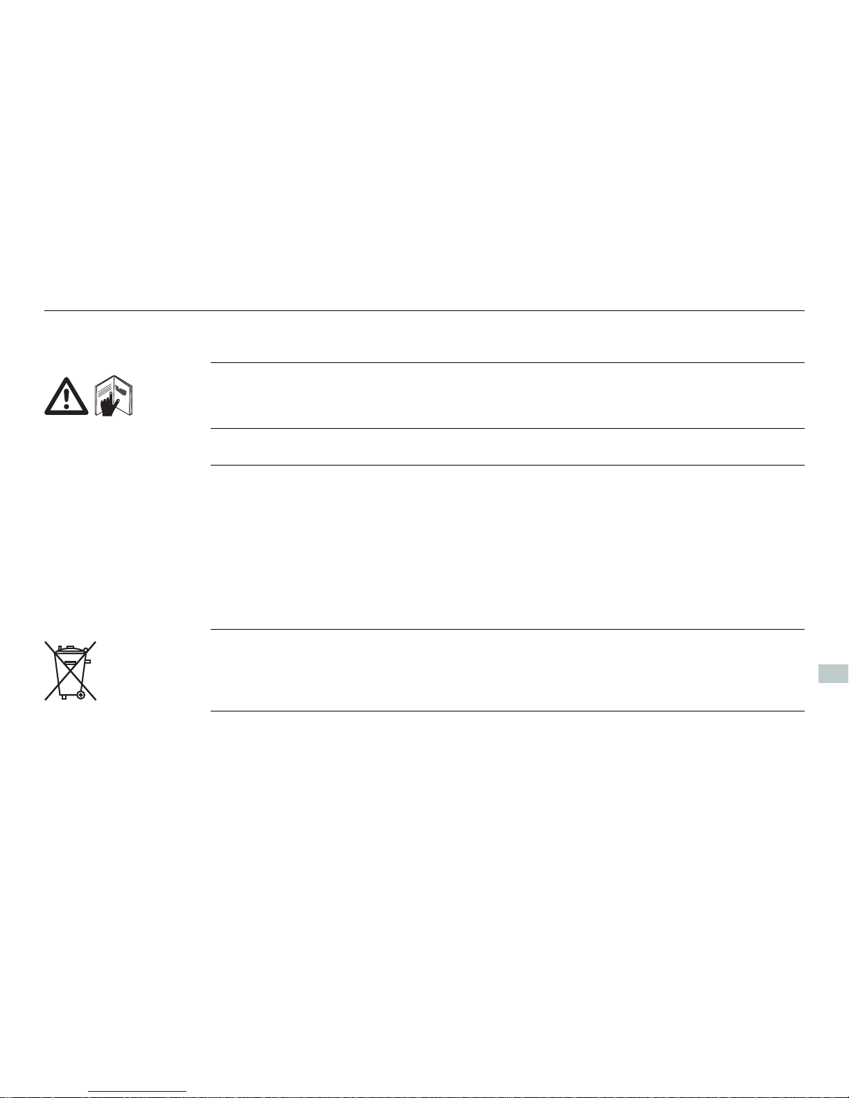
1 Important Information about your Instrument
Read and follow the User Manual on the accompanying USB card before using the
product.
Keep for future reference!
Intended use • Computing with software.
• Carrying out measurement tasks using various GNSS measuring techniques.
• Recording GNSS and point related data.
• Remote control of product.
• Data communication with external appliances.
• Measuring raw data and computing coordinates using carrier phase and code
signal from GNSS satellites.
The product must not be disposed with household waste.

iCON gps 80, Important Information about your Instrument 3
en
Conformity to
national regulations
• FCC Part 15, 22, 24 and 27 (applicable in US)
• Hereby, Leica Geosystems AG, declares that the product iCON gps 80 is in compliance with the essential requirements and other relevant provisions of Directive
1999/5/EC. The declaration of conformity can be consulted at http://www.leicageosystems.com/ce.
Class 1 equipment according European Directive 1999/5/EC (R&TTE)
can be placed on the market and be put into service without restrictions in any EEA member state.
• The conformity for countries with other national regulations not covered by the
FCC part 15, 22, 24 and 27 or European directive 1999/5/EC has to be approved
prior to use and operation.
• Japanese Radio Law and Japanese Telecommunications Business Law Compliance.
– This device is granted pursuant to the Japanese Radio Law and the Japanese
Telecommunications Business Law.
– This device should not be modified (otherwise the granted designation
number will become invalid).

4
iCON gps 80, Instrument Components
en
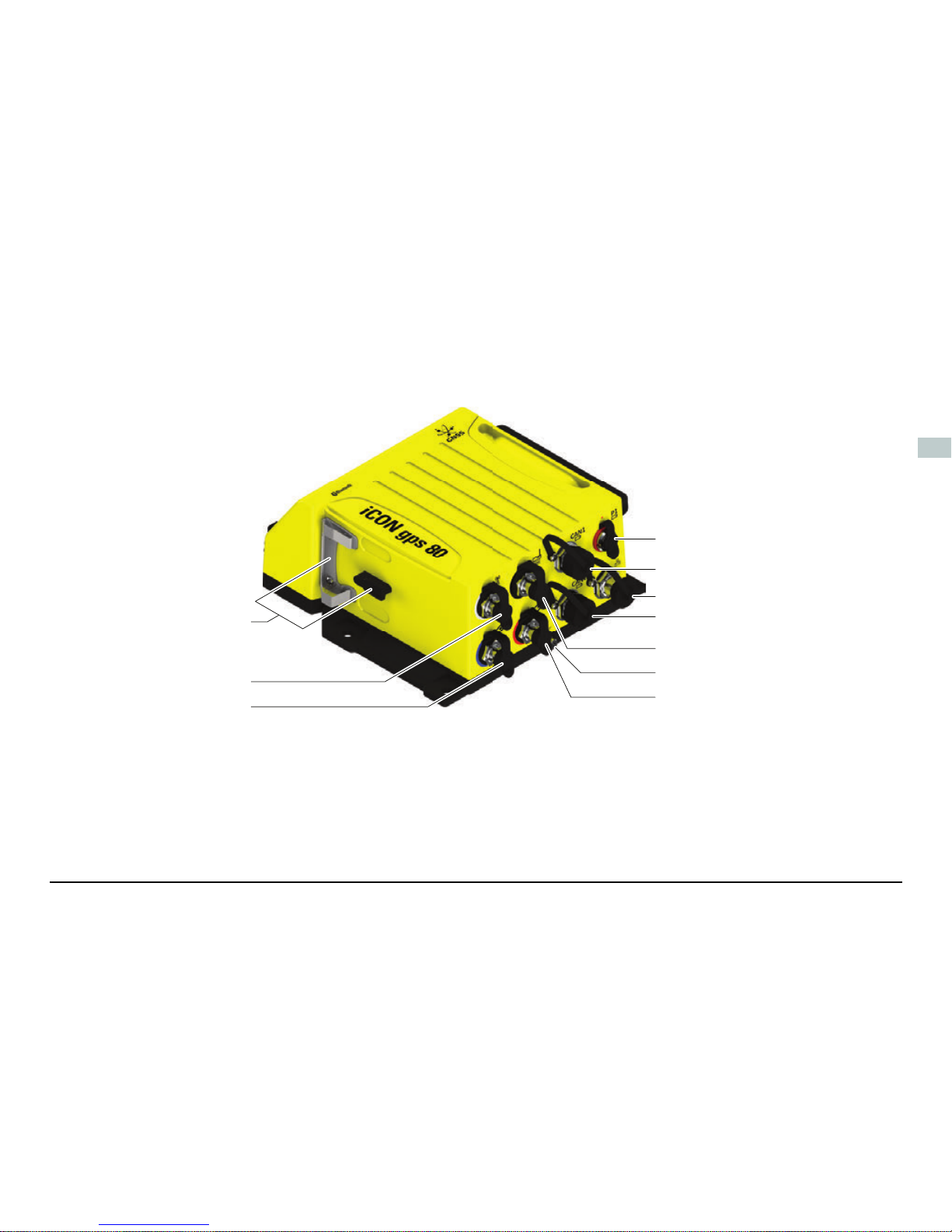
2 Instrument Components
iCG81/iCG82
components
Front view:
a) RS232 port P2
b) Power and status LED,
Ambient light sensor
c) ON/OFF button
d) Display
e) Keyboard
f) Tripod fastening clip
g) Cover for USB port
h) Mounting holes
i) Carrying handle, optional
accessory
j) Radio cover, SIM card and
slot-in-device compartment
005681_001
a
c
e
f
g
h
h
i
b
d
j
iCON gps 80, Instrument Components 5
en
Rear view:
a) Support for GFU device
b) External radio antenna
port
c) Primary External GNSS
antenna port
d) P1 Data/Power port
e) CAN1 Data/Power port
f) Ethernet port
g) CAN2 Data/Power port
h) External Modem
antenna port
i) Grounding screw
j) Secondary external
GNSS antenna port,
iCG82 only
005682_001
a
b
c
d
e
f
g
h
i
j

6
iCON gps 80, Instrument Components
en
Port Description
USB 2.0 USB A data port, for data exchange, software updates.
P1 (8-pin LEMO 1, female) Power input, serial interface for data input/output,
and PPS.
P2 (8-pin LEMO 1, female) RS232 for connection of an external radio device.
RADIO For connection of an external radio antenna.
CAN1, CAN2 Power input and data input/output. CAN ports are
connected internally so connection order is not important.
ANT1, ANT2 GNSS antenna input.
ANT1 is always the primary GNSS antenna and ANT2 is
always the secondary (heading) GNSS antenna.
MODEM For connection of an external antenna for the internal
4G modem.
iCON gps 80, Instrument Components 7
en
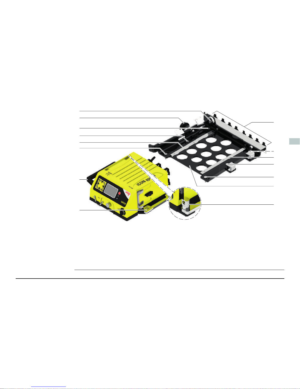
CMB6 components
a) Feed through for Padlock
b) Locking bolt
c) Mounting screws, for vehicle
mounting
d) Guiding rail
e) Carrying handle, optional accessory
for iCON gps 80
f) Clamping rail
g) Dummy plugs for cable storage
h) Quick Release Base Bracket
i) Locking bolt for Padlock
005862_002
a
b
c
d
c
c
g
c
c
e
f
c
d
h
i

8
iCON gps 80, Technical Data
en
3 Technical Data
Environmental
specifications
Temperature
Protection against water, dust and sand
Humidity
Type Operating temperature [°C] Storage temperature [°C]
Instrument -40 to +65 -55 to +85
Type Protection
Instrument IP67 (IEC 60529)
Dust tight
Waterproof to 1 m temporary immersion
Type Protection
Instrument Up to 100 %
The effects of condensation are to be effectively counteracted by periodically drying out the instrument.

iCON gps 80, Technical Data 9
en
Vibration/Shock
Type iCON gps 80 CGA60
Vibration 5 - 5000 Hz, ± 1.5 mm, 0.7 g
IEC60068-2-6
MIL-STD 810G - 514.6E-1-Cat24
MIL-STD 810G - 514.6C-3-Cat4
10 - 10000 Hz, ± 1.5 mm, 10 g
8 - 150 Hz, ± 15 mm, 15 g
ISO9022-36-08
MIL-STD 810F – 514.5-Cat24
Shock 60 g, 6 ms, IS09022 100 g, 2 ms

10
iCON gps 80, Care and Transport
en
4 Care and Transport
Care and transport • Carry the product in its original container or carry the tripod with its legs splayed
across your shoulder, to protect the product against shock and vibration.
• Periodically carry out test measurements and perform the field adjustments indicated in the User Manual, particularly after the product has been dropped, stored
for long periods or transported.

iCON gps 80, Operation 11
en
5 Operation
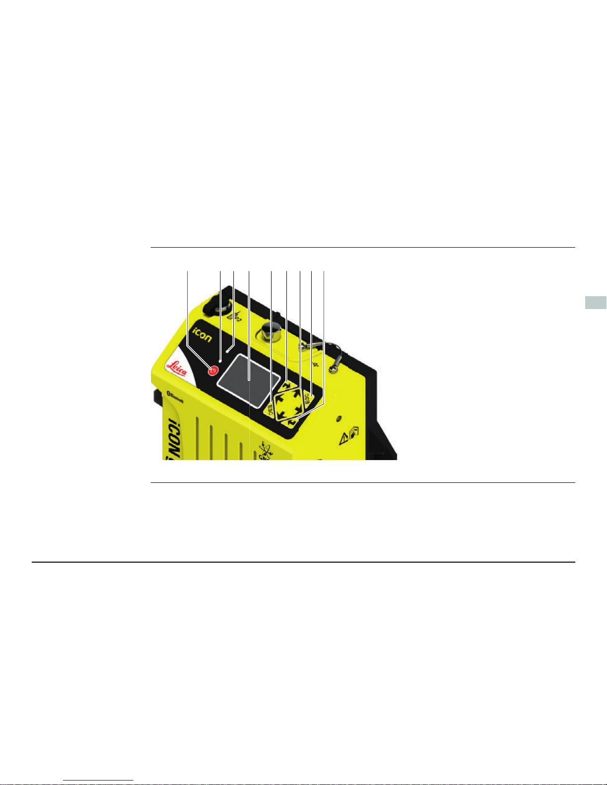
User Interface
overview
a) ON/OFF key
b) Power and status LED
c) Ambient light sensor
d) Display
e) ESC key
f) ENTER key
g) Navigation keys
005683_001
fab ecd efg
12
iCON gps 80, Operation
en
User Interface
elements
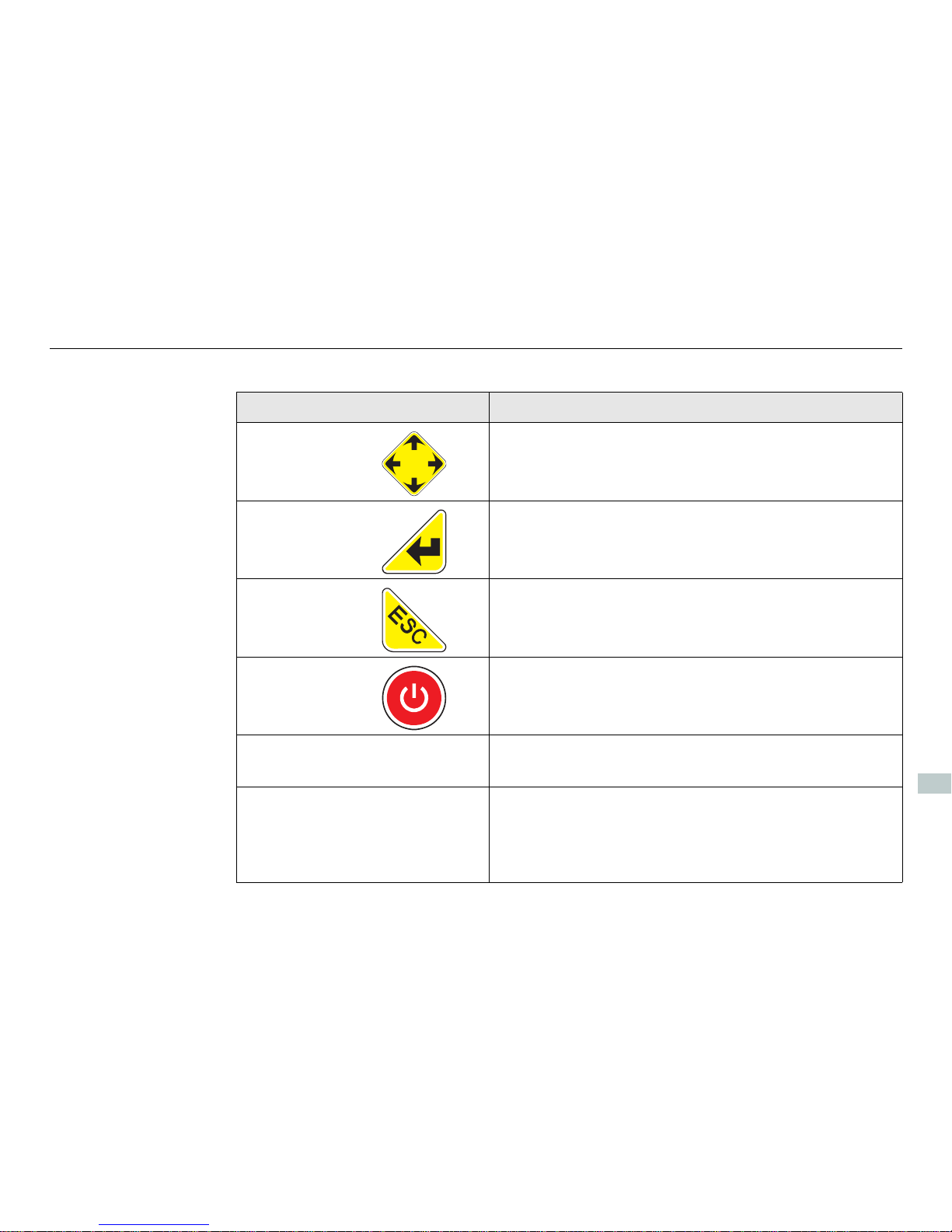
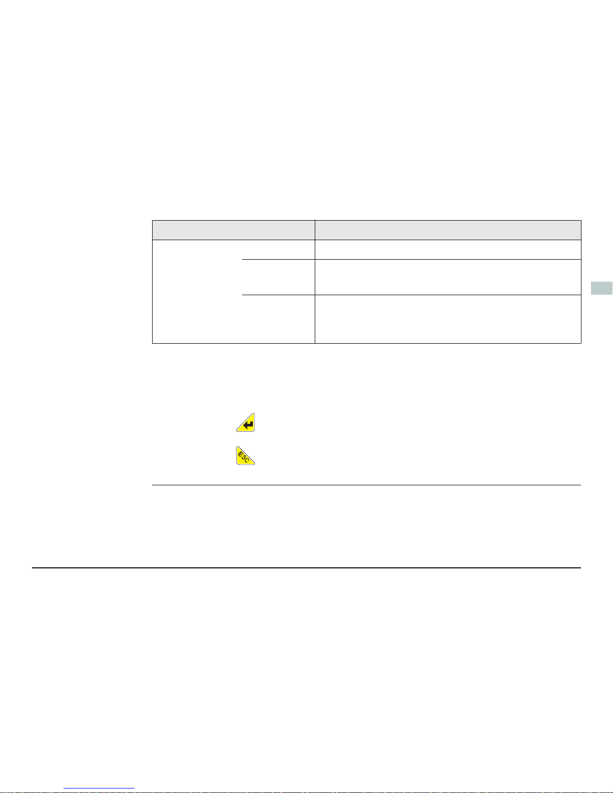
The instrument can be controlled via the user interface elements.
Element Function
Navigation keys 4-way navigation in the menus via left, right, up
and down key.
Enter key • To activate editing.
• To accept changes.
• To enter a menu or submenu.
ESC key • To cancel operations.
• To leave a menu or submenu.
ON/OFF key Gives access to startup and shutdown: press for
three seconds.
Display Displays status information and software func-
tions.
Ambient light
sensor
Energy saving ambient light sensor.
When the display Backlight is set to Auto,
the Backlight intensity is automatically
adjusted on the ambient light sensor input.
iCON gps 80, Operation 13
en
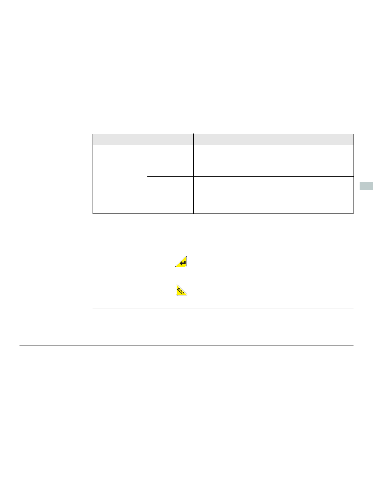
Use the and navigation keys to select a menu icon and to navigate
within submenus.
Use the key to enter a submenu and confirm settings.
Use the key to discard settings, cancel operations and to go back one
menu level.
Power LED off Instrument is switched off.
continuously green
• Normal operation mode.
• Position acquired.
continuously red
• During start-up of the instrument.
• For various errors occuring. The current status
information is shown on the display.
Element Function

14
iCON gps 80, Operation
en
Display orientation To enable a proper view on the display for various mounting options the iCON gps 80
allows to flip the screen, providing a up-side-down use of the display.
1) Access the wizard via Settings > Syst em C on figuration > Screen Settings.
2) Choose the Flip Screen setting to meet your needs:
No: for the default display orientation.
Yes: to rotate the display orientation by 180°.
3) Press to confirm your setting. The display orientation is changed immediately.
iCON gps 80, Operation 15
en
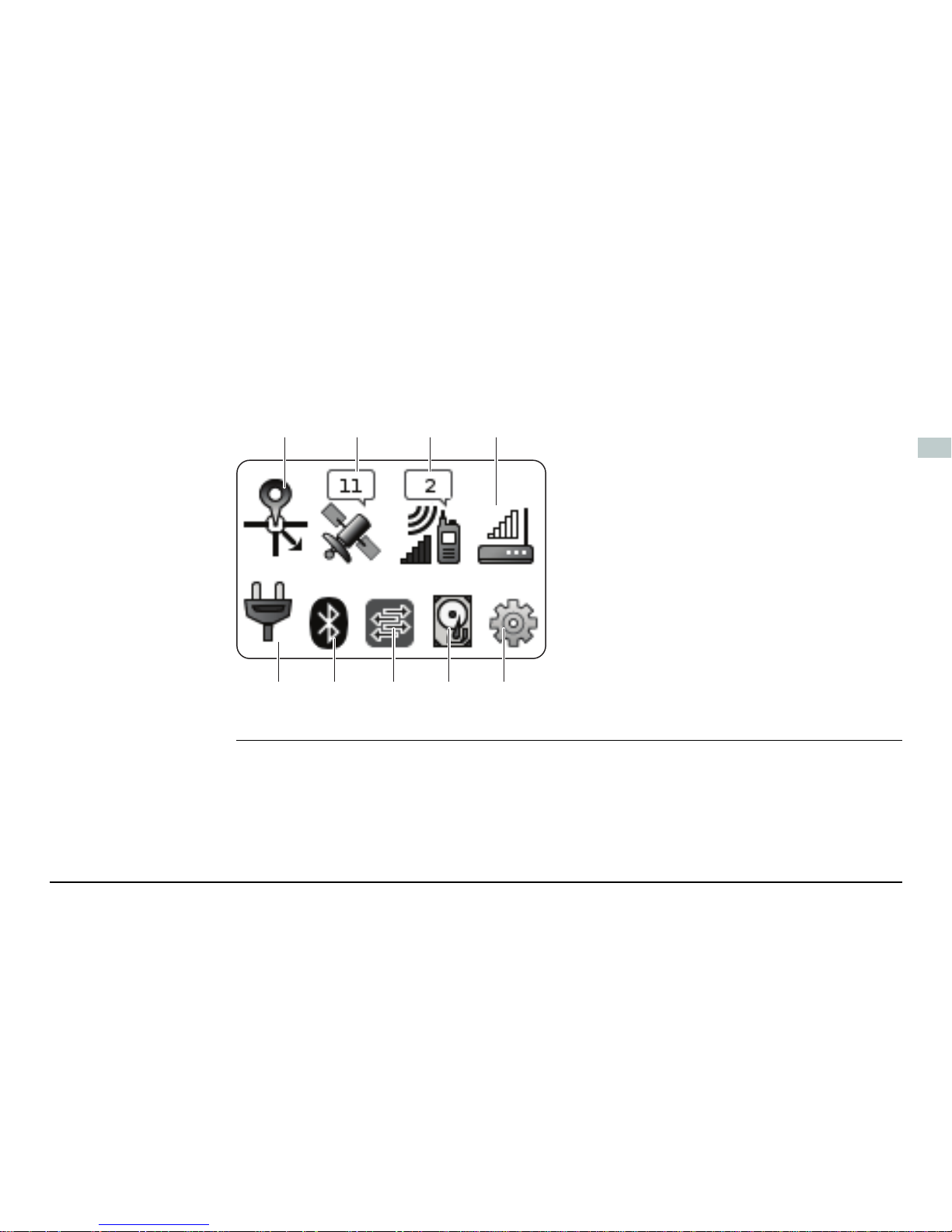
Main Menu content The Main Menu features a matrix set of menu icons.
The appearance of the menu icons depend upon the current instrument
status and setup.
a) Position icon
b) Satellite icon
c) Radio icon
d) Modem icon
e) Power icon
f) Bluetooth icon
g) iCON telematics/Port Summary icon
h) Memory and logging icon
i) Settings icon
005871_001
abcd
ef ghi

Leica Geosystems AG
Heinrich-Wild-Strasse
CH-9435 Heerbrugg
Switzerland
Phone +41 71 727 31 31
www.leica-geosystems.com
818311-2.6.0en
Original text
Printed in Switzerland
© 2015 Leica Geosystems AG, Heerbrugg, Switzerland

de
Leica iCON gps 80
Quick Guide
Version 2.6
Deutsch
2
iCON gps 80, Wichtige Informationen über Ihr Instrument
de
1 Wichtige Informationen über Ihr Instrument
Lesen und befolgen Sie die Gebrauchsanweisung auf der beigefügten USB-Karte,
bevor Sie das Produkt verwenden.
Bewahren Sie den Quick Guide sorgfältig auf!
Verwendungszweck • Berechnung mit Software.
• Durchführung von Messaufgaben mit verschiedenen GNSS Messtechniken.
• Aufzeichnung von GNSS und punktbezogenen Daten.
• Fernsteuerung des Produkts.
• Datenkommunikation mit externen Geräten.
• Messung von Rohdaten und Berechnen von Koordinaten mit Hilfe von Trägerphase und Codesignalen von GNSS Satelliten.
Das Produkt darf nicht im Hausmüll entsorgt werden.

iCON gps 80, Wichtige Informationen über Ihr Instrument 3
de
Konformität mit
nationalen
Vorschriften
• FCC Teil 15, 22, 24 und 27 (gültig in den USA)
• Hiermit erklärt Leica Geosystems AG, dass das iCON gps 80 die grundlegenden
Anforderungen und sonstigen relevanten Vorschriften der Richtlinie 1999/5/EG
erfüllt. Die Konformitätserklärung kann unter http://www.leicageosystems.com/ce eingesehen werden.
Geräte der Klasse 1 entsprechend der Europäischen Richtlinie
1999/5/EG (R&TTE) können ohne Einschränkung in jedem Mitgliedsstaat des EWR vermarktet und in Betrieb genommen werden.
• In Ländern mit nationalen Vorschriften, die nicht mit der europäischen Richtlinie
1999/5/EG oder FCC Teil 15, 22, 24 und 27 abgedeckt sind, sind die Bestimmungen und Zulassungen für den Betrieb zu prüfen.
• Einhaltung des japanischen Fernmeldegesetzes.
– Dieses Gerät ist gemäß dem japanischen Fernmeldegesetz zugelassen.
– Dieses Gerät sollte nicht verändert werden (andernfalls wird die vergebene
Zulassungsnummer ungültig).

4
iCON gps 80, Instrumentenkomponenten
de
2 Instrumentenkomponenten
iCG81/iCG82
Komponenten
Vorderansicht:
a) RS232 Port P2
b) Strom- und Status-LED,
Umgebungslichtsensor
c) EIN/AUS-Taste
d) Display
e) Tastatur
f) Stativbefestigungsklammer
g) Abdeckung des USB-Ports
h) Montageöffnungen
i) Tragegriff, optionales
Zubehör
j) Funkdeckel, Fach für SIM-
Karten und Einschubgeräte
005681_001
a
c
e
f
g
h
h
i
b
d
j

iCON gps 80, Instrumentenkomponenten 5
de
Rückansicht:
a) GFU-Gerätehalterung
b) Port für externe
Antenne
c) Haupt-Port für externe
GNSS Antenne
d) P1-Daten-/Strom-Port
e) CAN1-Daten-/Strom-
Port
f) Ethernet-Port
g) CAN2-Daten-/Strom-
Port
h) Port für externe Mode-
mantenne
i) Erdungsschraube
j) Zweit-Port für externe
GNSS Antenne, nur
iCG82
005682_001
a
b
c
d
e
f
g
h
i
j

6
iCON gps 80, Instrumentenkomponenten
de
Anschluss Beschreibung
USB 2.0 USB A Datenport für Datenaustausch, Software-
Aktualisierung.
P1 (8-polig LEMO 1, Buchse) Stromeingang, serielle Schnittstelle für Daten
Eingabe/Ausgabe und PPS.
P2 (8-polig LEMO 1, Buchse) RS232 zum Anschluss externer Funkgeräte.
RADIO Zum Anschluss externer Funkantennen.
CAN1, CAN2 Stromeingang und Dateneingabe/-ausgabe. CAN-
Ports sind intern verbunden, daher ist die
Anschlussreihenfolge unerheblich.
ANT1, ANT2 GNSS Antenneneingabe.
ANT1 ist immer die Haupt-GNSS Antenne und ANT2
ist die sekundäre (Peilungs-)GNSS Antenne.
MODEM Zum Anschluss externer Antennen für das interne
4G-Modem.

iCON gps 80, Instrumentenkomponenten 7
de
CMB6 Komponenten
a) Durchführung für Vorhängeschloss
b) Verriegelungsbolzen
c) Montierschrauben zur Befestigung
am Fahrzeug
d) Führungsschiene
e) Tragegriff, optionales Zubehör für
iCON gps 80
f) Klemmschiene
g) Blindstecker zur Kabelaufbewahrung
h) Quick Release Base Bracket
i) Verriegelungsbolzen für Schloss
005862_002
a
b
c
d
c
c
g
c
c
e
f
c
d
h
i

8
iCON gps 80, Technische Daten
de
3 Technische Daten
Umweltspezifikationen
Temperatur
Wasser- und Staubschutz
Feuchtigkeit
Typ Betriebstemperatur [°C] Lagertemperatur [°C]
Instrument -40 bis +65 -55 bis +85
Typ Schutz
Instrument IP67 (IEC 60529)
Staubdicht
Wasserdicht bis 1 m bei temporärem Eintauchen
Typ Schutz
Instrument Bis zu 100 %
Den Auswirkungen von Kondensation sollte durch periodisches Austrocknen des Instruments entgegengewirkt werden.

iCON gps 80, Technische Daten 9
de
Vibration/
Erschütterung
Typ iCON gps 80 CGA60
Vibration 5 - 5000 Hz, ± 1,5 mm, 0,7 g
IEC60068-2-6
MIL-STD 810G - 514.6E-1-Cat24
MIL-STD 810G - 514.6C-3-Cat4
10 - 10000 Hz, ± 1,5 mm, 10 g
8 - 150 Hz, ± 15 mm, 15 g
ISO9022-36-08
MIL-STD 810F – 514.5-Cat24
Stöße 60 g, 6 ms, IS09022 100 g, 2 ms

10
iCON gps 80, Wartung und Transport
de
4 Wartung und Transport
Wartung und
Transport
• Transportieren Sie das Produkt in seinem Originalbehälter oder tragen Sie das
Stativ mit aufgesetztem und angeschraubtem Produkt aufrecht zwischen den
Stativbeinen über der Schulter, um das Produkt gegen Schläge und Vibrationen
zu sichern.
• Führen Sie periodisch Testmessungen durch und wenden Sie die in der
Gebrauchsanweisung beschriebene Feldjustierung an, besonders nach einem
Sturz, nach einer langen Lagerung oder nach einem Transport des Produkts.
iCON gps 80, Bedienung 11
de
5 Bedienung
Überblick über die
Benutzeroberfläche
a) EIN/AUS Taste
b) Strom und Status LED
c) Sensor für Umgebungs-
licht
d) Anzeige
e) ESC Taste
f) ENTER Taste
g) Navigationstasten
005683_001
fab ecd efg

12
iCON gps 80, Bedienung
de
Bedienelemente
der Benutzeroberfläche
Das Instrument kann über die Benutzeroberfläche gesteuert werden.
Element Funktion
Navigationstasten
4-fach Navigation in den Menüs über Links-,
Rechts-, Auf- und Abtaste.
Enter-Taste • Aktivieren der Eingabe.
• Übernahme der Änderungen.
• Öffnen eines Menüs oder Untermenüs.
ESC Taste • Abbrechen von Anwendungen.
• Verlassen eines Menüs oder Untermenüs.
EIN/AUS Taste Zugriff auf Startup und Shutdown: drei Sekunden
drücken.
Anzeige Anzeige von Statusinformationen und Software
Funktionen.
Sensor für
Umgebungslicht
Stromsparender Umgebungslichtsensor.
Bei der Einstellung Beleuchtung auf Auto
wird die Hintergrundbeleuchtungsintensität automatisch auf Grund der Umgebungslichtsensormessung eingestellt.
iCON gps 80, Bedienung 13
de
Wählen Sie mit den und Navigationstasten die Menü Symbole und navigieren damit in den Untermenüs.
Verwenden Sie die Taste, um ein Untermenü zu öffnen und Einstellungen
zu bestätigen.
Verwenden Sie die Taste, um Einstellungen zu verwerfen, Anwendungen
abzubrechen und zurück zum Hauptmenü zu gelangen.
Betriebsanzeige
LED
aus Das Instrument ist ausgeschaltet.
permanent
grün
• Normaler Betriebsmodus.
• Position erfasst.
permanent
rot
• Bei Starten des Instrumentes.
• Bei verschiedenen Fehlermeldungen. Aktuelle
Statusinformationen werden am Display angezeigt.
Element Funktion
 Loading...