

Leica iCON excavate iCP41 User Manual
Leica iCON excavate iCP41
User Manual
Version 2.0
English

2iCON excavate iCP41, Introduction
Introduction
Purchase Congratulations on your purchase of the iCON excavate iCP41.
The iCON excavate iCP41 is an ideal tool for increasing productivity in all aspects of the
construction earthmoving industry.
This manual contains important safety directions as well as instructions for setting up the
system and operating it. Refer to "9 Safety Directions" for further information.
Read carefully through the User Manual before you switch on the product.
To ensure safety when using the system, please also observe the directions and instructions
contained in the User Manual and Safety Handbook issued by the:
• Machine manufacturer and
• System manufacturer.
Product
identification
The type and serial number of your products are indicated on the label on the base of the
unit.
Enter the model and serial number in your manual and always refer to this information when
you need to contact your agency or Leica Geosystems authorised service workshop.
Type: iCON excavate iCP41 Serial No.: _________________________

iCON excavate iCP41, Introduction 3
Symbols The symbols used in this manual have the following meanings:
Trademarks • GSM is a trademark owned by the GSM Association.
All other trademarks are the property of their respective owners.
Validity of this manual This manual applies to the iCON excavate iCP41.
To use the iCON excavate iCP41 efficiently it’s inalienable to refer to the manual provided
together with the software running on the iCON excavate iCP41.
Type Description
Danger Indicates an imminently hazardous situation which, if not avoided,
will result in death or serious injury.
Warning Indicates a potentially hazardous situation or an unintended use
which, if not avoided, could result in death or serious injury.
Caution Indicates a potentially hazardous situation or an unintended use
which, if not avoided, may result in minor or moderate injury
and/or appreciable material, financial and environmental damage.
Important paragraphs which must be adhered to in practice as they
enable the product to be used in a technically correct and efficient
manner.

4iCON excavate iCP41, Table of Contents
Table of Contents
In this manual Chapter Page
1 Product Overview 8
1.1 Product Description and Features 8
1.2 Container Contents 10
2 Commissioning 11
2.1 Installation 11
2.2 Installation a SIM Card/USB-Stick 14
2.3 Inspection Prior to Commissioning 15
2.4 Commissioning 15
3 Setting the Direction of X 16
42D Run Mode 21
4.1 Control Box 2D Mode 21
4.2 Single Slope Mode without Laser 23
4.3 Single Slope Mode with Laser 25
4.4 Dual Slope Mode 29
4.5 2D User Menu Tree 32
4.6 2D User Menu 34
4.6.1 SETUP SYSTEM 35
4.6.2 SETUP HEIGHT 37
4.6.3 CALIBRATION WIZARD 39
4.6.4 DUAL SLOPE 50
4.6.5 MEASURE 51
4.6.6 PROFILE 52

iCON excavate iCP41, Table of Contents 5
4.6.7 CABLE DETECTION 59
4.6.8 SERVICE MENU 60
4.7 Reversed Bucket 61
4.8 Quick Settings 62
4.9 Special Working Situations 64
4.9.1 Tilt Sensor 64
4.9.2 Using an Auger 66
4.10 Diagnose Screen 70
53D Run Mode 71
5.1 Control Box 3D 71
5.2 Storing Points 73
5.3 Auto logging function 74
5.4 Avoidance zones 80
5.5 Resetting the Rotation Calibration, Single GPS Only 83
5.6 Vertical Offset 84
5.7 Changing the bucket reference point 86
5.8 Screen Settings 86
5.9 Other Settings 87
5.10 Working with Terrain Models 88
5.10.1 Guide Line 88
5.10.2 Locking Cross Slope 90
5.11 Working with MBS (Volume Calculation Model) 93
5.11.1 Selecting a Guide Line 93
5.11.2 Holding Slopes 94
5.12 Working with String Line Models 97
5.13 Monitor Screen 103
5.14 Switching Between Single and Dual GPS (PowerBox) 104
5.15 Transferring Files via USB 105
5.16 Selecting Projects and Reference Models 106

6iCON excavate iCP41, Table of Contents
5.17 Localisation Settings (Coordinate Systems) 108
5.18 iCON telematics 113
6 TPS Machine Guidance 115
6.1 Search Screen 116
6.2 Search Methods 117
6.3 Target Snap / Exclusion List 119
6.4 Vertical TPS Widget 120
6.5 Settings and TPS Information 121
6.6 Quick Search 122
6.7 Set up Communication between TPS and iCON 3D 123
7 iCON gps 80 124
7.1 The iCON gps 80 GNSS receiver 124
8 Care and Transport 133
8.1 General Notices 133
8.2 Transport 133
8.3 Storage 134
8.4 Cleaning and Drying 134
9 Safety Directions 135
9.1 General 135
9.2 Intended Use 135
9.3 Limits of Use 136
9.4 Responsibilities 136
9.5 Hazards of Use 137
9.6 Electromagnetic Compatibility EMC 141
9.7 ICES-003 Statement, Applicable in Canada 142
9.8 FCC Statement, Applicable in U.S. 143

iCON excavate iCP41, Table of Contents 7
10 Technical Data 150
10.1 iCON excavate iCP41 Technical Data 150
10.2 General Technical Data 152
10.3 Conformity to National Regulations 156
11 International Limited Warranty, Software License Agreement 158

8iCON excavate iCP41, Product Overview
1Product Overview
1.1 Product Description and Features
General The iCON excavate iCP41 has a key pad and touch screen for user input. The display is a 7"
wide screen and has state of the art brightness, making it possible to use in sunny environments.
The rugged IP56 enclosure is designed for harsh environments.
Power Supply and
Communication
For utmost reliability in harsh and dusty environment, no connecting cables or power supply
plugs are used at the iCON excavate iCP41.
"Cradle" will be used as a short form for MMB1300 cradle throughout this manual.
• The iCON excavate iCP41 is wirelessly powered over the cradle via induction.
• Data are transferred wirelessly via IR between the MMB1300 cradle and the iCON
excavate iCP41.
• The iCON excavate iCP41 has WLAN hardware support (for future use).
• On the bottom of the iCON excavate iCP41 are connectors for SIM card and USB.

iCON excavate iCP41, Product Overview 9
iCON excavate iCP41
• Do not cover the IR-Port for data transfer as this can lead to a transfer interruption.
• Both, the HSPA and the WiFi antenna are not attached to the iCON excavate iCP41 when
delivered.
• To store the iCON excavate iCP41 inside the transport case both antennas must be detached.
a) Keypad
b) 7" LCD wide screen display
c) WiFi antenna
d) IR-Port for data transfer
e) HSPA antenna
f) Reverse SMA Connectors
g) Ventilation cap
h) SIM card connector
i) USB 2.0 connector
j) Cover for communication ports
iCP41_001
aabcde
ffgh i j
10iCON excavate iCP41, Product Overview
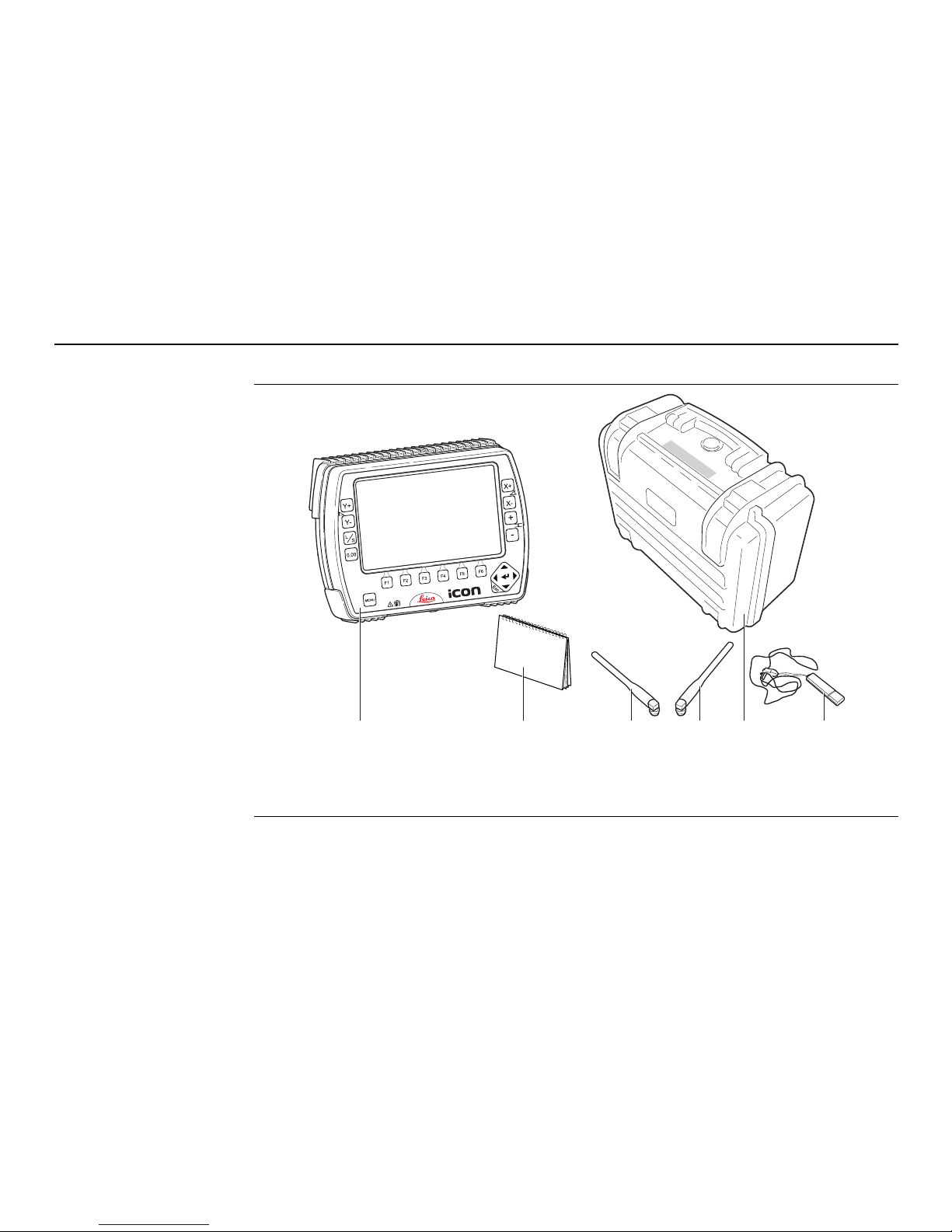
1.2 Container Contents
Container for instrument and delivered
accessories
a) iCON excavate iCP41
b) UserManual
c) WiFi antenna
d) HSPA antenna
e) Transport case
f) USB memory stick
iCP41_002
abcdef

iCON excavate iCP41, Commissioning 11
2 Commissioning
2.1 Installation
Warning This product may be installed on building machinery only by an appropriately trained and
qualified specialist.
Warning Unauthorised modification of machines by mounting the product may alter the function and
safety of the machine.
Precautions:
Follow the instructions of the machine manufacturer. If no appropriate instruction is available, ask machine manufacturer for instructions before mounting the product.
12iCON excavate iCP41, Commissioning
Installation
information
The iCON excavate iCP41 is ready to use when delivered from factory, no installation procedure is needed.
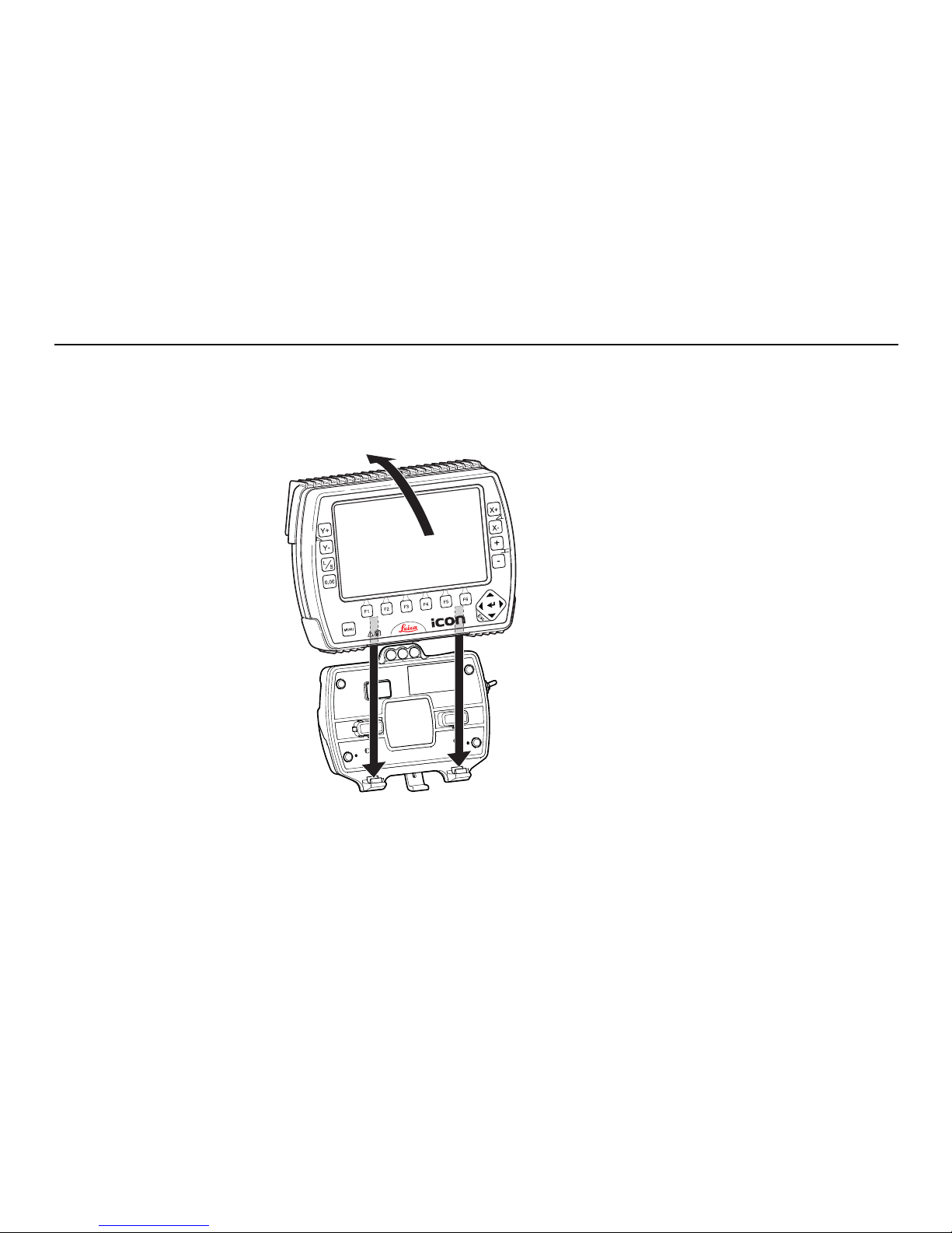
To get the iCON excavate iCP41 started complete the following steps:
1. Snap iCON excavate iCP41 onto cradle.
To connect the iCON excavate iCP41 to the
cradle:
1. Put the iCON excavate iCP41 on the
holding hooks in the bottom of the
cradle.
2. Then snap the iCON excavate iCP41 onto
the cradle by pressing it towards the
cradle.
iCP41_003
1
1
2
iCON excavate iCP41, Commissioning 13
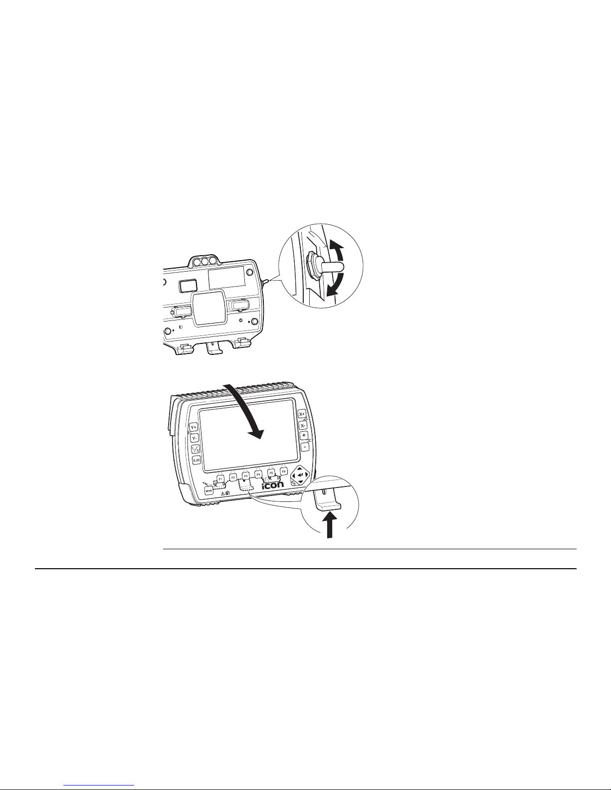
2. Turn iCON excavate iCP41 on.
To turn the iCON excavate iCP41 on and off,
use the power switch on the right side of the
cradle. This is the master switch for the
entire system.
Removing the iCON excavate iCP41 will
also turn off the power.
To release the iCON excavate iCP41
simply press the release key at the
bottom of the cradle and pull the iCON
excavate iCP41 towards you and then
lift it up.
iCP41_004
iCP41_005
1
2
14iCON excavate iCP41, Commissioning
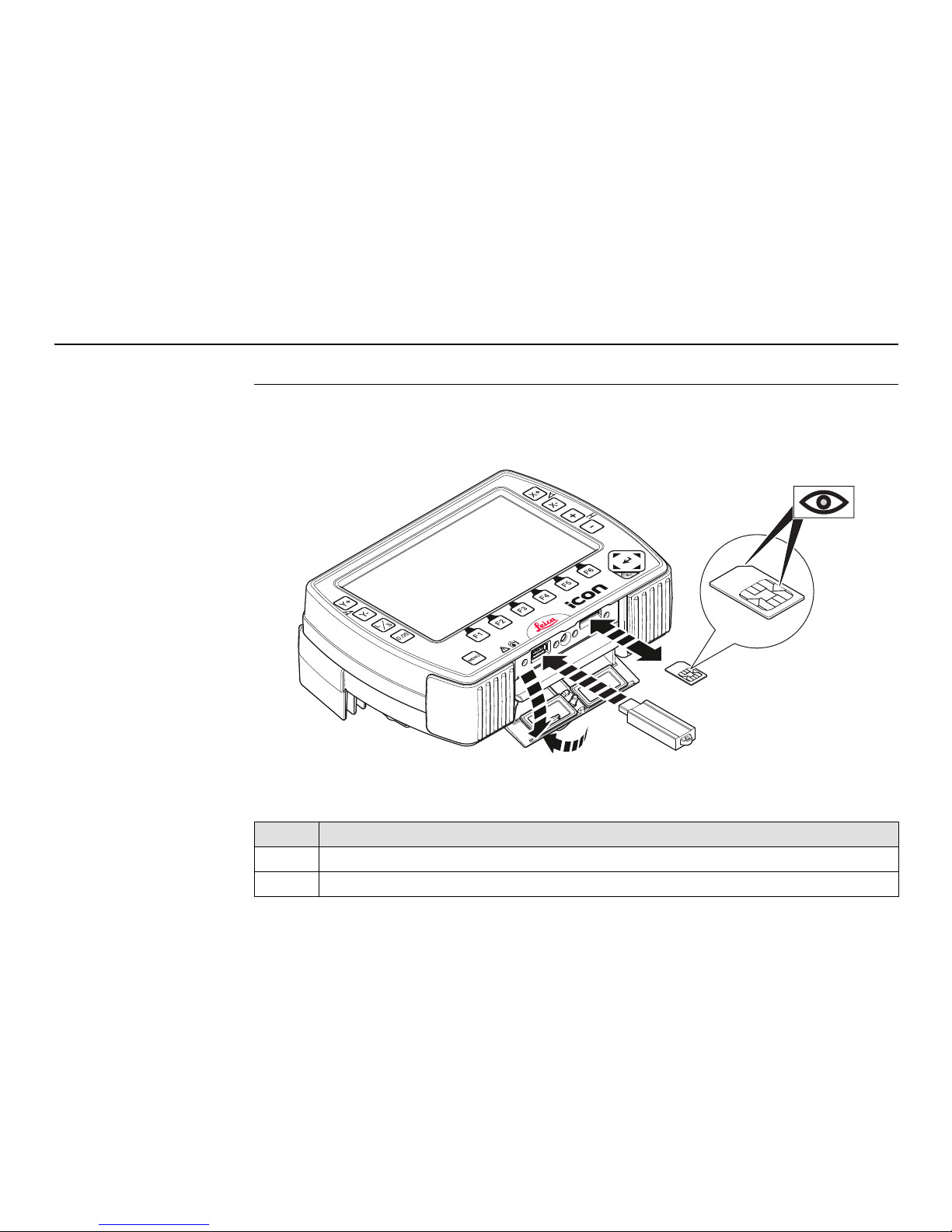
2.2 Installation a SIM Card/USB-Stick
Insert and remove a
SIM card/USB-Stick
step-by-step
Follow the step-by-step instructions to install a SIM card/USB-Stick.
To remove the SIM card/USB-Stick place the instrument on a stable surface first. Then
follow the following instructions in reverse order.
Place the instrument onto a stable surface. (Not illustrated)
Step Description
1. Rotate the ring to the left.
2. Pull the ring to open the protection cap.
iCP41_019
1
2
3
4
5

iCON excavate iCP41, Commissioning 15
2.3 Inspection Prior to Commissioning
Inspection 1. Check that the cradle on/off switch is put into off position.
2. Check that the iCON excavate iCP41 is readily snapped into the cradle.
3. Check that the cradle LEDs are operating normally.
•The top led should blink to show that messages are being transmitted from the
CANbus over the IR link.
• The middle LED should blink to show that messages are being received from the
CANbus over the IR link.
• The bottom LED should remain on to show that the cradle has sufficient power.
2.4 Commissioning
Power supply The iCON excavate iCP41 is powered in the following way:
• Induction based power through the backside of the iCON excavate iCP41 facing the
cradle.
3. Orientate the SIM card as illustrated.
4. Insert the SIM card into the card slot and push it in until it locks in place.
5. Insert the USB-Stick into the USB slot and push it in until it locks in place.
Step Description
16iCON excavate iCP41, Setting the Direction of X
3 Setting the Direction of X
Description The Direction of X is the main direction of the excavator boom.
It is very important to set the Direction of X when working in Dual Slope Mode.
There are two ways to set the Direction of X.
The traditional way is to use the one-point method where the correct Direction of X is
already known.
The more advanced way is to use the two-point method. You can use this method when
working with a string line for example.
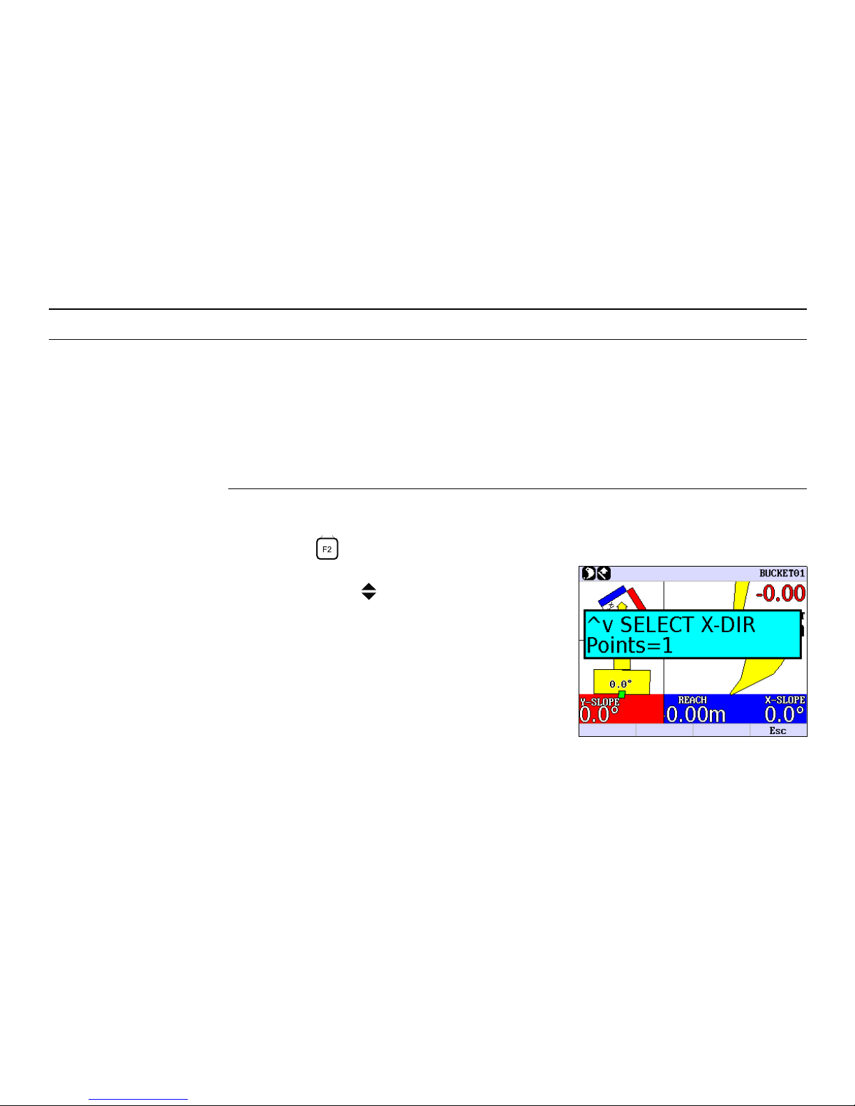
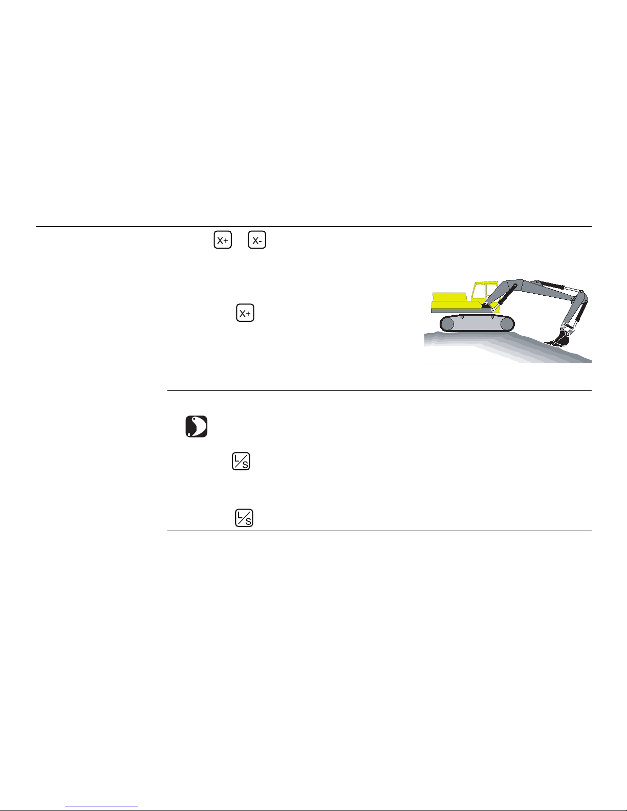
One-point method This is how you set the Direction of X using the One-point method:
1. Press the button, which will open the Direction of X menu.
2. Select One-point method by pressing the
up/down arrows .
iCON excavate iCP41, Setting the Direction of X 17
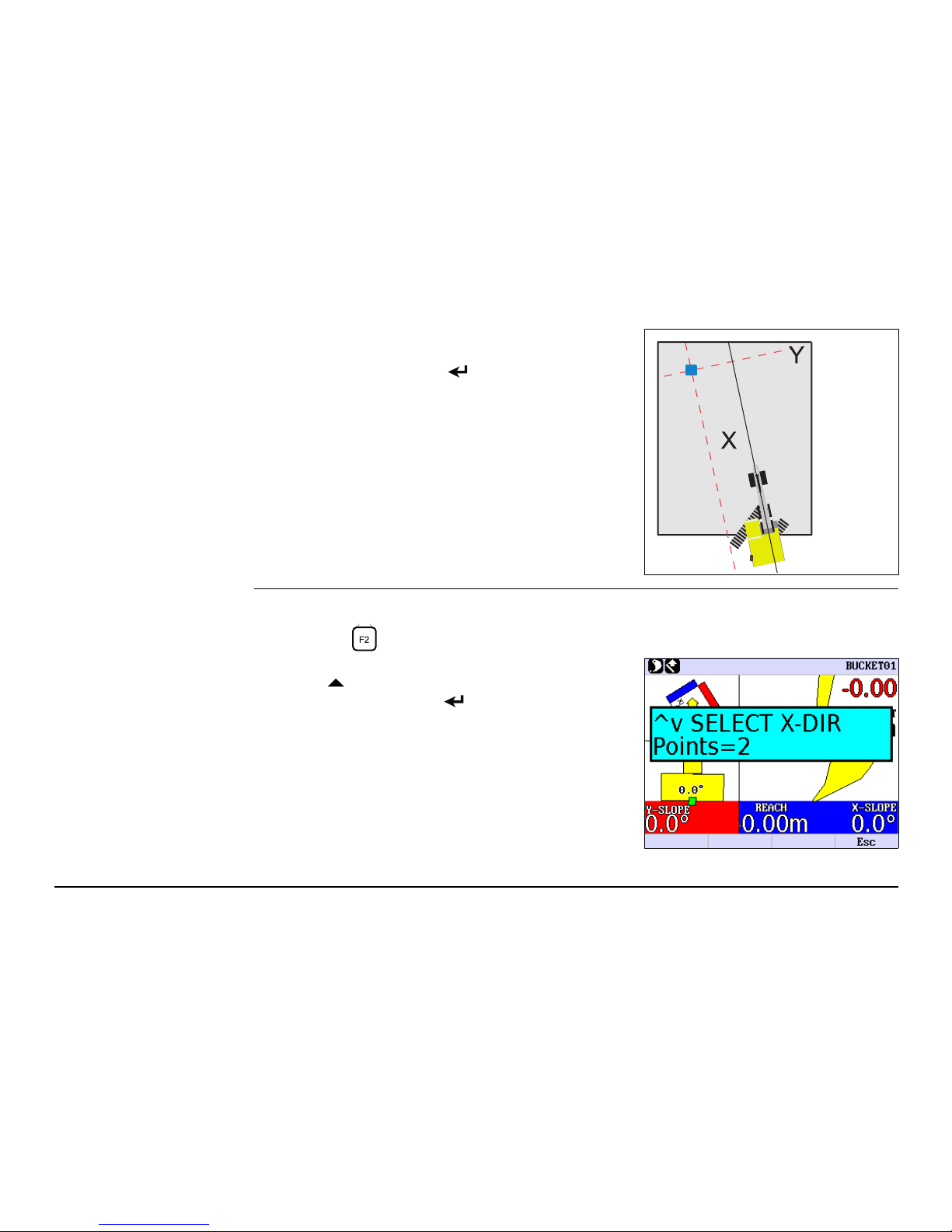
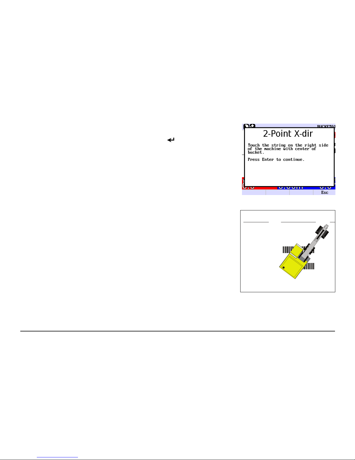
Two-point method This is how you set the X direction using the Two-point method:
1. Press the button, which will open the Direction of X menu.
3. Turn the machine so that the boom points
towards the Direction of X.
4. Press the Enter button to save the Direction
of X.
2. Select Two-point method by pressing the up
arrow .
3. Press the Enter button to enter the Two-point
method.
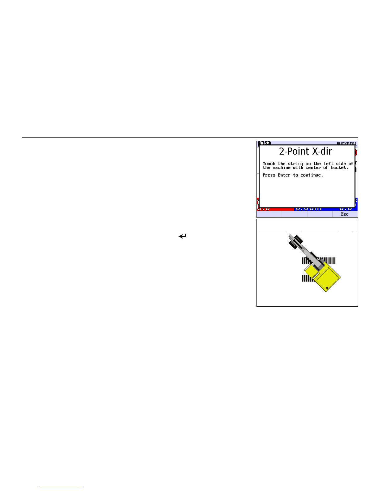
18iCON excavate iCP41, Setting the Direction of X
4. Place the centre of the bucket on point 1 (left side
of the machine).
5. Press the Enter button to save point 1.
a) Point 1 (left side of the machine)
b) Point 2 (right side of the machine)
ab
XX
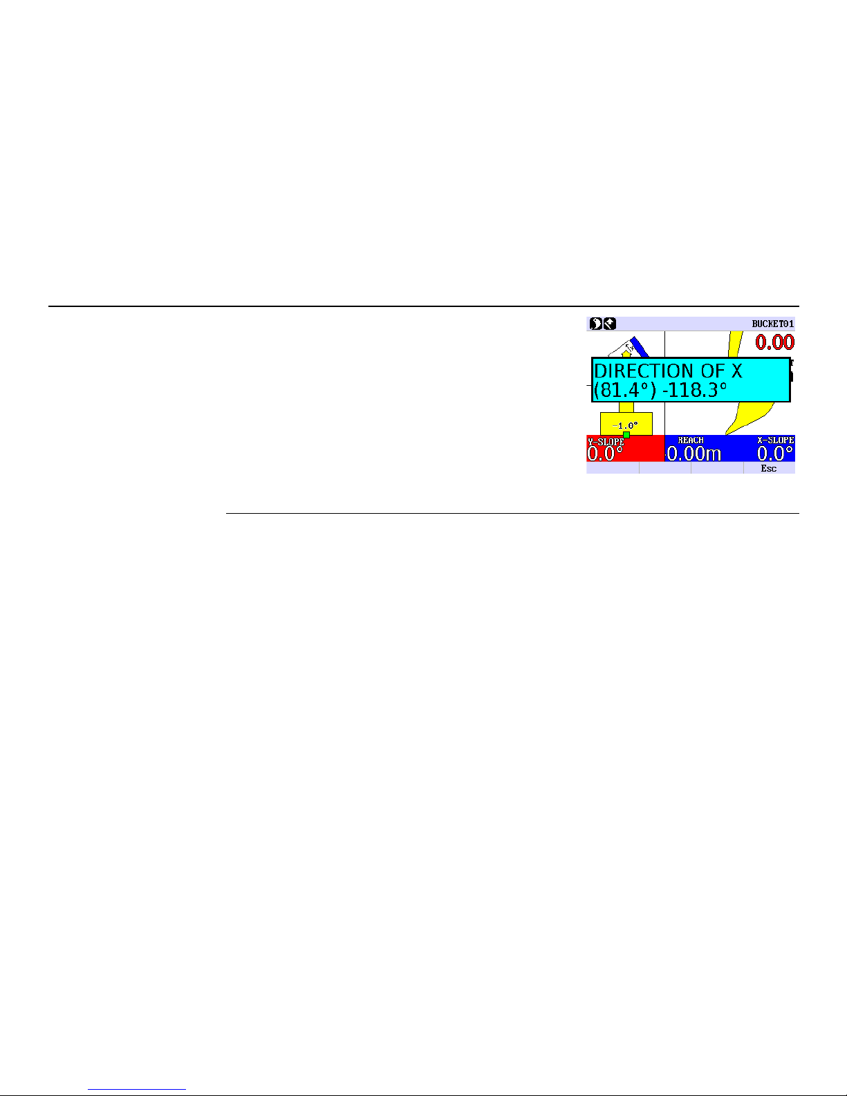
iCON excavate iCP41, Setting the Direction of X 19
6. Place the centre of the bucket on point 2 (right
side of the machine).
7. Press the Enter button to save point 2.
The Direction of X has now been set to be exactly
between the two points that were touched.
a) Point 1 (left side of the machine)
b) Point 2 (right side of the machine)
XX
ab
20iCON excavate iCP41, Setting the Direction of X

iCON excavate iCP41, 2D Run Mode 21
42D Run Mode
4.1 Control Box 2D Mode
Control Box Description of display
a) Height measurement direction:
NORMAL / VERTICAL
b) Reference Method:
LASER / BUCKET / 3D
c) Bucket / Tilt angle indicator.
d) Direction of X.
e) Shows the position of the bucket:
Background is yellow for HIGH, green for ON
GRADE and red for LOW.
f) Tilt slope display.
Active when tilt sensor is connected.
g) Remaining depth (in red), until
ON GRADE.
h) Y-slope.
i) Selected bucket.
j) Desired offset above/below reference
height.
k) Bucket’s position.
l) X-slope.
m) Bucket angle indicator.
n) Reach measurement.
OFFSET
-5.00
Y-SLOPE
1.0%
6.8%
X-SLOPE
4.0%
R=0.04
BUCKET 1
0.0
%
OFFSET
-
2.76
TILTBUCKET
Y-SLOPE
X-SLOPE
R=
0.81
11.5
%
14.5
%
REACH
REACH
X
-
SLOPE
SLOPE
1.00
1.00
-3.00
5.0%
5.0%
Y
-
SLOPE
SLOPE
12.0%
12.0%
11.9%
BUCKET02
OFFSET
iCP41_006
a
b
c
d
e
f
g
h
i
j
k
l
m
n
22iCON excavate iCP41, 2D Run Mode
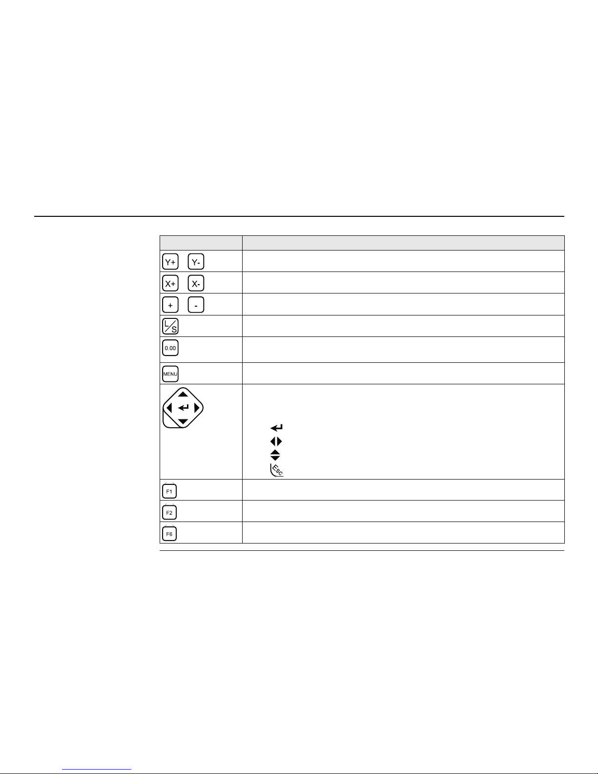
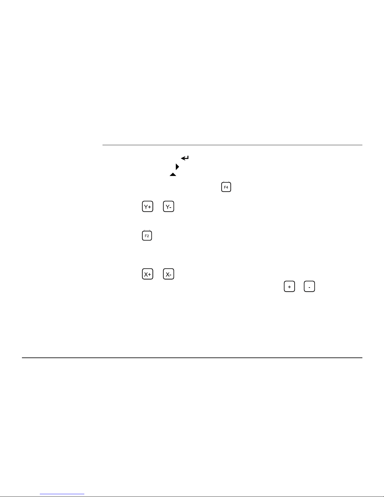
Description of buttons
Button Description
Increases/decreases slope in Y-direction.
Increases/decreases slope in X-direction.
Increases/decreases offset.
Read and save setup height.
Reset button. Used for setting the reference level and resetting earlier
values in the menu.
Selecting a bucket.
Navigation button. Allows you to navigate through the menus.
Press left/right arrows to move between bucket items.
Naming convention within this manual:
• : Enter button
• : Left / Right arrow buttons
• : Up / Down arrow buttons
• : Escape button
Quick settings. Up to 10 user settings can be stored.
X-direction. Used for setting the X-direction.
Return to 3D main menu.
Esc
iCON excavate iCP41, 2D Run Mode 23
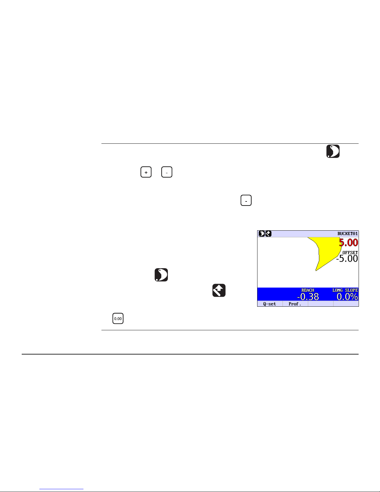
4.2 Single Slope Mode without Laser
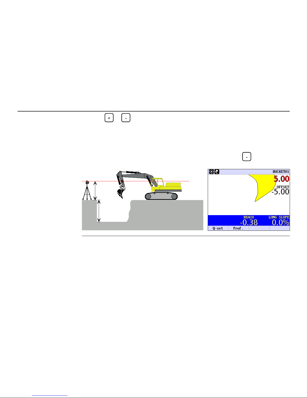
Setting the desired
offset
1. Make sure that LASER MODE is set to OFF (Bucket is selected as reference) in the
menu option SETUP HEIGHT -> LASER MODE.
2. Press the or button until the display shows the desired offset value.
Example
If you want to enter a offset of 5.0 m, press the button until the display shows the
value -5.00.
The display to the right indicates:
1. The bucket selected is No. 1.
2. The value in red 5.00 indicates the distance to
ONGRADE.
3. The desired offset is set to -5.00.
4. The X-slope is 0.0% (no slope).
5. The bucket tip is used as reference.
6. The distance is measured vertically .
7. REACH=-0.38 means that the bucket has been
moved 38 cm closer to the machine since the
button was pressed.
24iCON excavate iCP41, 2D Run Mode
Digging with slope in
X-direction
Press the or button until the display shows the slope desired.
Example:
Moving the excavator 1. Make sure that OFF is selected in the menu option SETUP HEIGHT -> LASER MODE
.
2. Put the bucket at a place that can be reached again after moving the excavator.
3. Press the button to store the position.
The red display will flash to indicate that the position is stored.
4. Move the excavator and put the bucket at exactly the same place where the position
above was stored.
5. Press the button again to load the position.
If you want a slope where the excavation is getting
shallower as the bucket comes nearer the excavator,
press the right button until the display shows the
desired slope.
Positive slope
iCON excavate iCP41, 2D Run Mode 25
4.3 Single Slope Mode with Laser
Basic operation
instructions
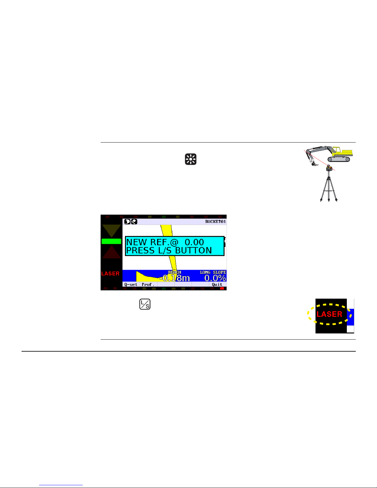
1. Make sure that INTEGRATED is selected in the menu option SETUP
HEIGHT -> LASER MODE .
2. Make sure that the rotation laser is activated.
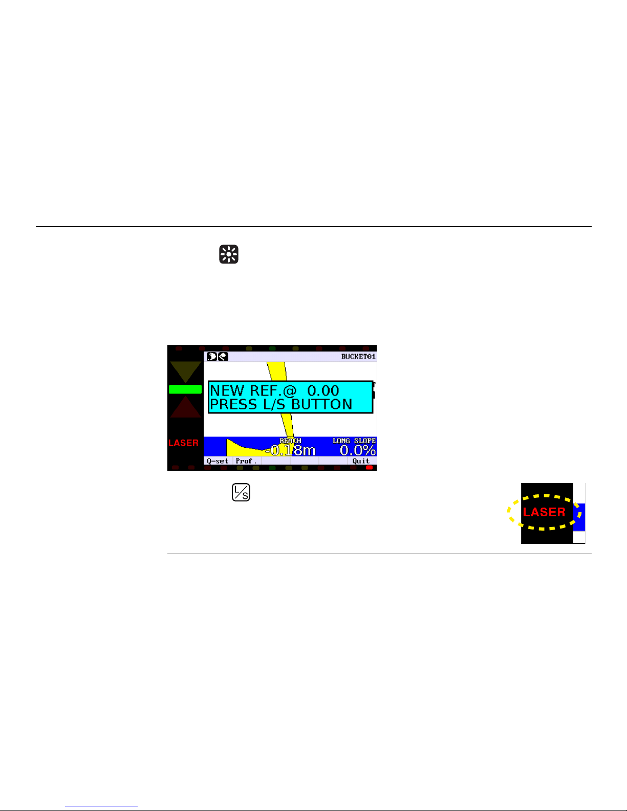
3. Move the laser sensor, so that it can detect the laser beam.
When the sensor detects the beam, the message
NEW REF. @ 0.00
PRESS L/S KEY
is shown in the display.
When the sensor approaches the beam, the
indicators to the left side of the control box
indicate the direction in which the sensor is to
be moved in order to detect the laser beam.
4. Press the button to set the reference point.
When the display flashes the message LASER, the reference point
has been accepted. The values of actual Offset and desired Offset
depend on the actual position of stick and bucket.
RUGBY 400 DG
26iCON excavate iCP41, 2D Run Mode
Setting the desired
offset
Press the or button until the display shows the desired value.
Example:
If you want to enter a offset of 5.0 m below the laser beam, press the button until the
display shows the value -5.00.
The reference point is the laser beam.
RUGBY 400 DG
3.00 m
2.00 m
iCON excavate iCP41, 2D Run Mode 27
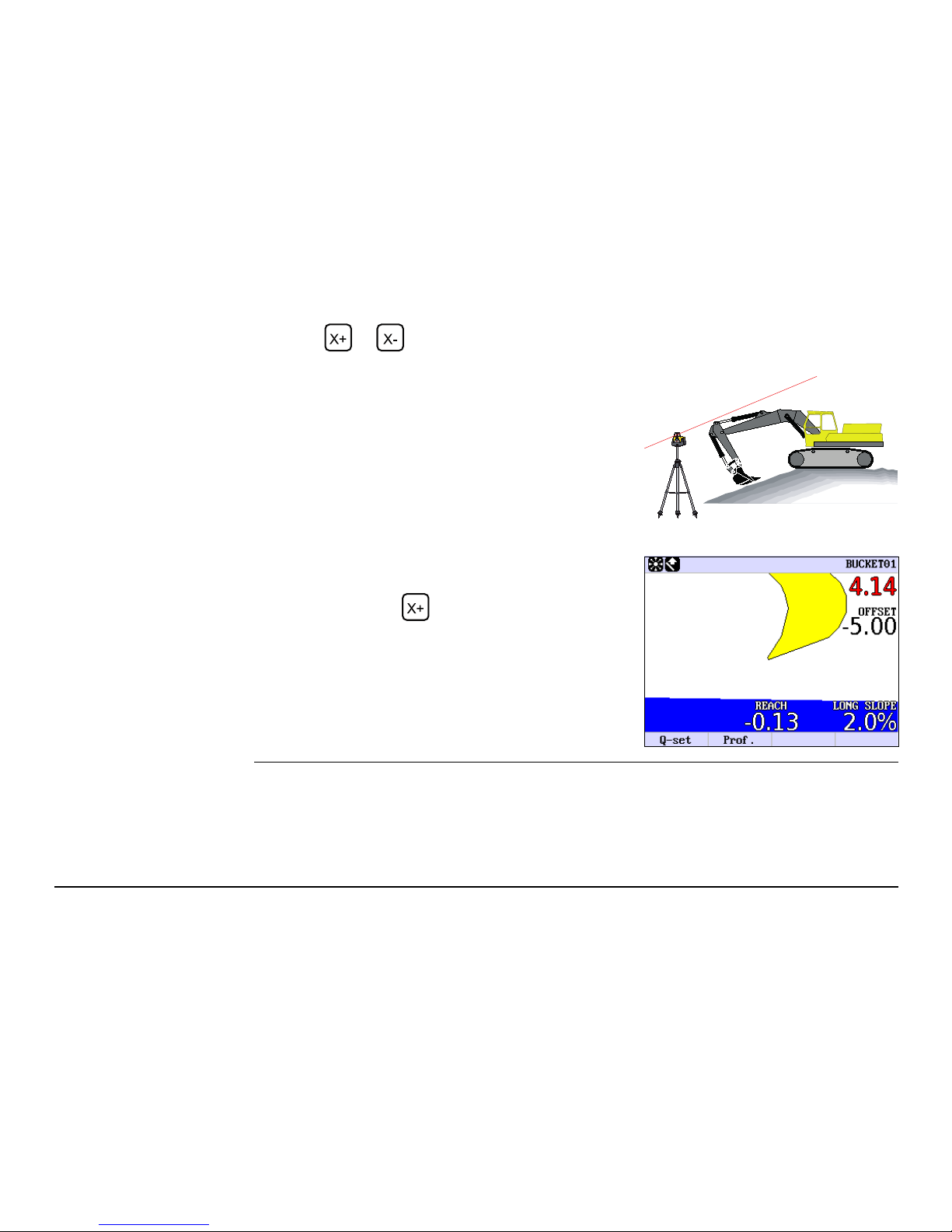
Digging with slope in
X-direction
Press the or button until the display shows the slope desired.
Example:
The slope you enter on the display must always
be the same as the slope of the rotation laser.
If you want a slope of 2%, where the excavation is
getting shallower as the bucket comes nearer the
excavator, press the button until the display
shows the value 2.0%.
RUGBY 400 DG
28iCON excavate iCP41, 2D Run Mode
Moving the excavator 1. Make sure that INTEGRATED is selected in the menu option SETUP HEIGHT -> LASER
MODE .
2. Move the excavator to the desired location.
3. Move the laser sensor, so that it can detect the laser beam.
When the sensor detects the beam, the message
NEW REF. @. 0.00
PRESS L/S KEY
is shown in the display.
When the sensor approaches the beam, the
indicators to the left side of the control box
indicate the direction in which the sensor is to
be moved in order to detect the laser beam.
4. Press the button to set the reference point.
When the display flashes the message LASER, the reference point
has been accepted. The values of actual Offset and desired Offset
depend on the actual position of stick and bucket.
iCON excavate iCP41, 2D Run Mode 29
4.4 Dual Slope Mode
Description 1. Turn on the display.
2. Press the Enter button . You will now enter the User Menu.
3. Press the right arrow to select the option DUAL SLOPE.
4. Press the up arrow to turn DUAL SLOPE ON or OFF.
5. Leave the User Menu by pressing the button.
6. Adjustment of Y slope.
Press the or button until the display shows the desired value.
7. Setting the Direction of X.
Turn the machine so that the bucket points towards the Direction of X.
Press the button, which sets the Direction of X .
8. Adjustment of X slope.
Press the or button until the display shows the desired value.
9. Adjust the offset underneath the laser beam by pressing the or button until the
display shows the desired value.
It is very important to set the Direction of X in Dual Slope Mode.
30iCON excavate iCP41, 2D Run Mode
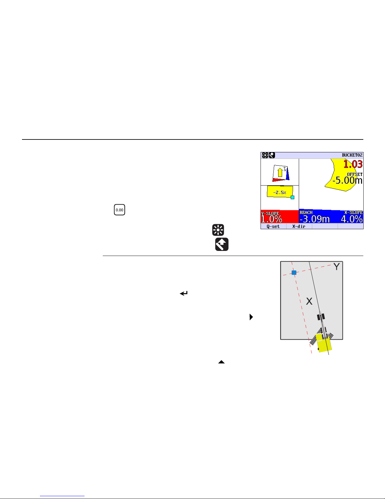
The display to the right indicates:
Example
4. Select ON by pressing the up arrow .
1. The bucket selected is No. 2.
2. The value in red 1.03 indicates the distance to
ONGRADE.
3. The desired offset is set to -5.00 m.
4. The X-slope is 4.0 %.
5. REACH=-3.09 m means that the bucket has been
moved 3.09 m closer to the machine since the
button was pressed.
6. The Y-slope is 1.0 %.
7. A laser beam is used as reference .
8. The distance is measured vertically .
The laser (blue) is adjusted to the following slopes
4.0% in the X direction and 1.0 % in the Y direction.
1. Turn on the display.
2. Press the Enter button . You will now enter the
User Menu.
3. Select DUAL SLOPE by pressing the right arrow .
 Loading...