

Page 1
50
403020
GPS Basics
Introduction to GPS (Global Positioning System)
Version 1.0
English
Page 2

Contents
Preface ........................................................... 4
1. What is GPS and what does it do ? .......... 5
2. System Overview ....................................... 6
2.1 The Space Segment ............................................... 6
2.2 The Control Segment .............................................. 8
2.3 The User Segment ................................................. 9
3. How GPS works ....................................... 10
3.1 Simple Navigation .................................................. 11
3.1.1 Satellite ranging .................................................... 11
3.1.2 Calculating the distance to the satellite ................. 13
3.1.3 Error Sources ........................................................ 14
3.1.4 Why are military receivers more accurate ? ........... 18
3.2 Differentially corrected positions (DGPS) ................19
3.2.1 The Reference Receiver ........................................ 20
3.2.2 The Rover receiver ................................................. 20
3.2.3 Further details ....................................................... 20
3.3 Differential Phase GPS and Ambiguity Resolution ... 22
3.3.1 The Carrier Phase, C/A and P-codes .................... 22
3.3.2 Why use Carrier Phase? ....................................... 23
3.3.3 Double Differencing............................................... 23
3.3.4 Ambiguity and Ambiguity Resolution ...................... 24
4. Geodetic Aspects ..................................... 26
4.1 Introduction ...........................................................27
4.2. The GPS coordinate system .................................28
4.3 Local coordinate systems ......................................29
4.4 Problems with height .............................................30
4.5 Transformations .....................................................31
4.6 Map Projections and Plane Coordinates ................. 34
4.6.1 The Transverse Mercator Projection ...................... 35
4.6.2 The Lambert Projection ......................................... 37
5. Surveying with GPS ................................ 38
5.1 GPS Measuring Techniques .................................. 39
5.1.1 Static Surveys ........................................................ 40
5.1.2 Rapid Static Surveys .............................................. 42
5.1.3 Kinematic Surveys ................................................. 44
5.1.4 RTK Surveys .......................................................... 45
5.2 Pre-survey preparation ........................................... 46
5.3 Tips during operation .............................................46
Glossary ....................................................... 48
Further Reading .......................................... 59
Index ............................................................. 60
2
GPS Basics -1.0.0en
Page 3
View of chapters
Preface
1. What is GPS and what does it do?
2. System Overview
3. How GPS works
4. Geodetic Aspects
5. Surveying with GPS
Glossary
Index
4
5
6
10
26
38
48
60
GPS Basics -1.0.0en
3
View of chapters
Page 4
Preface
Why have we written this book and
who should read it?
Leica manufactures, amongst other
things, GPS hardware and software.
This hardware and software is used by
many professionals in many applications. One thing that almost all of our
users have in common is that they are
not GPS scientists or experts in Geodesy. They are using GPS as a tool to
complete a task. Therefore, it is useful to
have background information about what
GPS is and how it works.
This book is intended to give a novice or
potential GPS user a background in the
subject of GPS and Geodesy. It is not a
definitive technical GPS or Geodesy
manual. There are many texts of this sort
available, some of which are included in
the reading list on the back pages.
This book is split into two main sections.
The first explains GPS and how it works.
The second explains the fundamentals
of geodesy.
Preface
4
GPS Basics -1.0.0en
Page 5

1. What is GPS and what does it do ?
GPS is the shortened form of NAVSTAR
GPS. This is an acronym for NAVigation
System with Time And Ranging Global
Positioning System.
GPS is a solution for one of mans
longest and most troublesome problems. It provides an answer to the
question Where on earth am I ?
One can imagine that this is an easy
question to answer. You can easily
locate yourself by looking at objects that
surround you and position yourself
relative to them. But what if you have no
objects around you ? What if you are in
the middle of the desert or in the middle
of the ocean ? For many centuries, this
problem was solved by using the sun
and stars to navigate. Also, on land,
surveyors and explorers used familiar
reference points from which to base their
measurements or find their way.
These methods worked well within
certain boundaries. Sun and stars
cannot be seen when it is cloudy. Also,
even with the most precise measurements position cannot be determined
very accurately.
After the second world war, it became
apparent to the U.S. Department of
Defense that a solution had to be found
to the problem of accurate, absolute
positioning. Several projects and
experiments ran during the next 25 years
or so, including Transit, Timation, Loran,
Decca etc. All of these projects allowed
positions to be determined but were
limited in accuracy or functionality.
At the beginning of the 1970s, a new
project was proposed GPS. This
concept promised to fulfill all the requirements of the US government, namely
that one should be able to determine
ones position accurately, at any point on
the earths surface, at any time, in any
weather conditions.
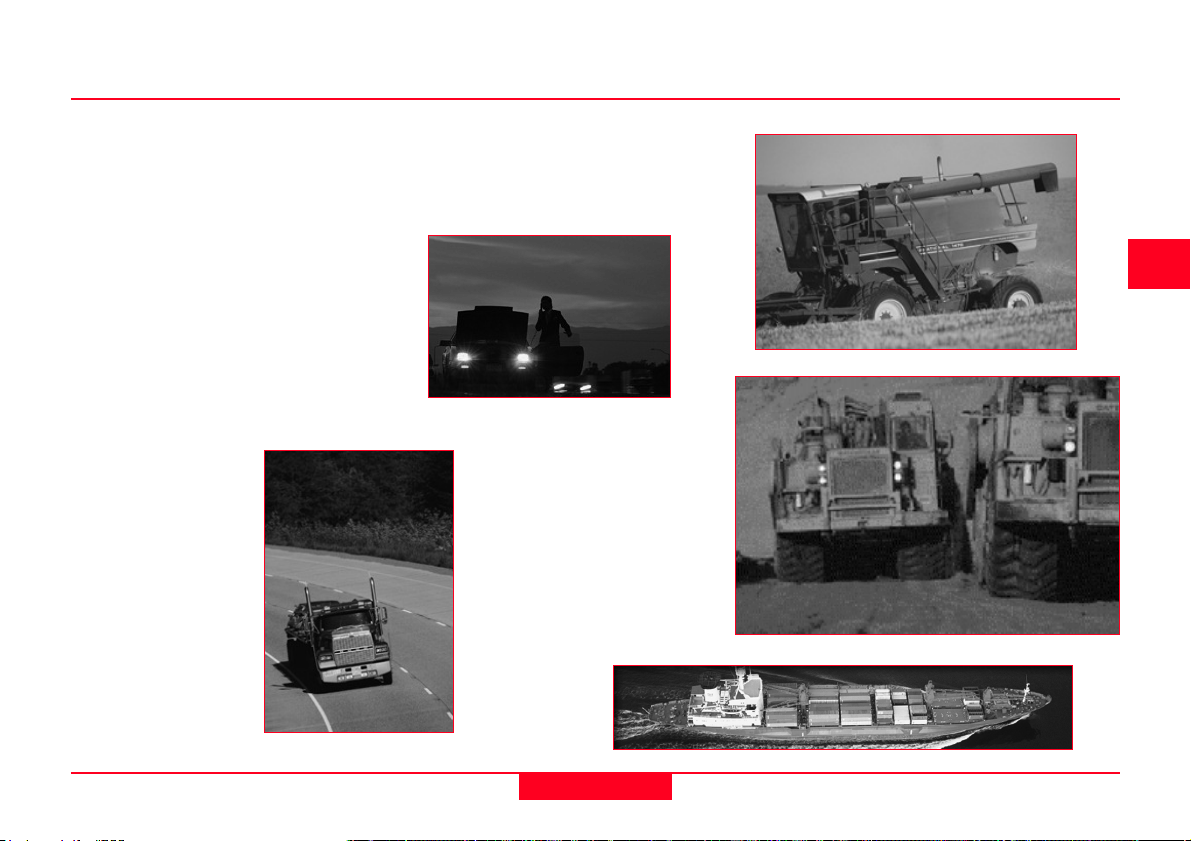
GPS is a satellite-based system that
uses a constellation of 24 satellites to
give a user an accurate position. It is
important at this point to define accurate. To a hiker or soldier in the desert,
accurate means about 15m. To a ship in
coastal waters, accurate means 5m. To
a land surveyor, accurate means 1cm or
less. GPS can be used to achieve all of
these accuracies in all of these applications, the difference being the type of
GPS receiver used and the technique
employed.
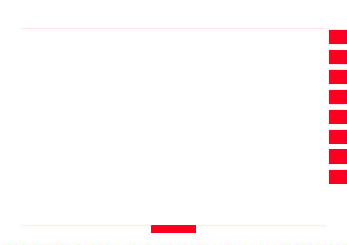
GPS was originally designed for military
use at any time anywhere on the surface
of the earth. Soon after the original
proposals were made, it became clear
that civilians could also use GPS, and
not only for personal positioning (as was
intended for the military). The first two
major civilian applications to emerge
were marine navigation and surveying.
Nowadays applications range from incar navigation through truck fleet management to automation of construction
machinery.
4
4
5
GPS Basics -1.0.0en
5
What is GPS and what does it do ?
System Overview
Page 6
2. System Overview
2.1 The Space Segment
The total GPS configuration is com-
prised of three distinct segments:
The Space Segment Satellites
orbiting the earth.
The Control Segment Stations
positioned on the earths equator to
control the satellites
The User Segment Anybody that
receives and uses the GPS signal.
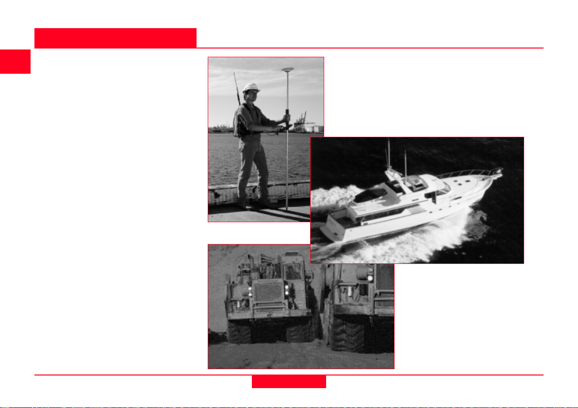
The Space Segment is designed to
consist of 24 satellites orbiting the earth
at approximately 20200km every 12
hours. At time of writing there are 26
operational satellites orbiting the earth.
GPS Satellite Constellation
The space segment is so designed that
there will be a minimum of 4 satellites
visible above a 15° cut-off angle at any
point of the earths surface at any one
time. Four satellites are the minimum
that must be visible for most applications. Experience shows that there are
usually at least 5 satellites visible above
15° for most of the time and quite often
there are 6 or 7 satellites visible.
GPS satellite
Each GPS satellite has several very
accurate atomic clocks on board. The
clocks operate at a fundamental frequency of 10.23MHz. This is used to
generate the signals that are broadcast
from the satellite.
System Overview
6
GPS Basics -1.0.0en
Page 7
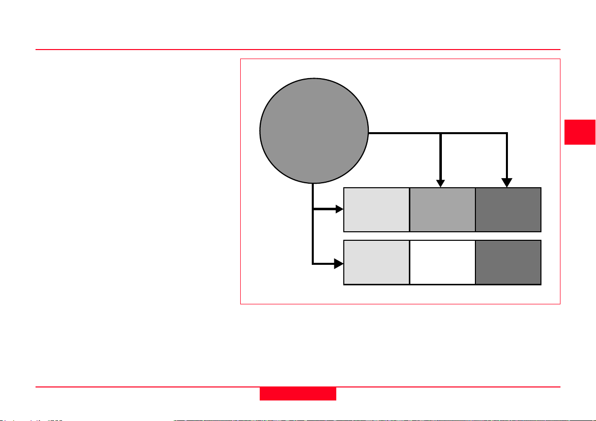
The satellites broadcast two carrier
waves constantly. These carrier waves
are in the L-Band (used for radio), and
travel to earth at the speed of light.
These carrier waves are derived from the
fundamental frequency, generated by a
very precise atomic clock:
• The L1 carrier is broadcast at 1575.42
MHz (10.23 x 154)
• The L2 carrier is broadcast at 1227.60
MHz (10.23 x 120).
The L1 carrier then has two codes
modulated upon it. The C/A Code or
Coarse/Acquisition Code is modulated
at 1.023MHz (10.23/10) and the P-code
or Precision Code is modulated at
10.23MHz). The L2 carrier has just one
code modulated upon it. The L2 P-code
is modulated at 10.23 MHz.
GPS receivers use the different codes to
distingush between satellites. The
codes can also be used as a basis for
making pseudorange measurements
and therefore calculate a position.
Fundamental
Frequency
10.23 Mhz
×154
×120
GPS Signal Structure
L1
1575.42 Mhz
L2
1227.60 Mhz
÷10
C/A Code
1.023 Mhz
4
5
P-Code
10.23 Mhz
P-Code
10.32 Mhz
GPS Basics -1.0.0en
7
System Overview
Page 8
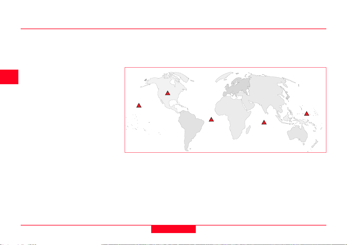
2.2 The Control Segment
The Control Segment consists of one
master control station, 5 monitor stations and 4 ground antennas distributed
amongst 5 locations roughly on the
earths equator.
The Control Segment tracks the GPS
satellites, updates their orbiting position
and calibrates and sychronises their
clocks.
A further important function is to determine the orbit of each satellite and
predict its path for the following 24
hours. This information is uploaded to
each satellite and subsequently broadcast from it. This enables the GPS
receiver to know where each satellite
can be expected to be found.
The satellite signals are read at Ascension, Diego Garcia and Kwajalein. The
measurements are then sent to the
Master Control Station in Colorado
Springs where they are processed to
determine any errors in each satellite.
The information is then sent back to the
four monitor stations equipped with
ground antennas and uploaded to the
satellites.
Colorado Springs
Haw aii
Ascension
Control Segment Station Locations
Kw ajalein
Diego G arcia
System Overview
8
GPS Basics -1.0.0en
Page 9
2.3 The User Segment
The User Segment comprises of anyone
using a GPS receiver to receive the GPS
signal and determine their position and/
or time. Typical applications within the
user segment are land navigation for
hikers, vehicle location, surveying,
marine navigation, aerial navigation,
machine control etc.
4
5
GPS Basics -1.0.0en
9
System Overview
Page 10
3. How GPS works
There are several different methods for
obtaining a position using GPS. The
method used depends on the accuracy
required by the user and the type of GPS
receiver available. Broadly speaking, the
techniques can be broken down into
three basic classes:
Autonomous Navigation using a single stand-alone receiver. Used by
hikers, ships that are far out at sea and the military. Position Accuracy is
better than 100m for civilian users and about 20m for military users.
Differentially corrected positioning. More commonly known
as DGPS, this gives an accuracy of between 0.5-5m. Used for
inshore marine navigation, GIS data acquisition, precision
farming etc.
Differential Phase position. Gives an accuracy of 0.5-20mm.
Used for many surveying tasks, machine control etc.
How GPS works
10
GPS Basics -1.0.0en
Page 11
3.1 Simple Navigation
3.1.1 Satellite ranging
This is the most simple technique
employed by GPS receivers to instantaneously give a position and height and/
or accurate time to a user. The accuracy
obtained is better than 100m (usually
around the 30-50m mark) for civilian
users and 5-15m for military users. The
reasons for the difference between
civilian and military accuracies are given
later in this section. Receivers used for
this type of operation are typically small,
highly portable handheld units with a
low cost.
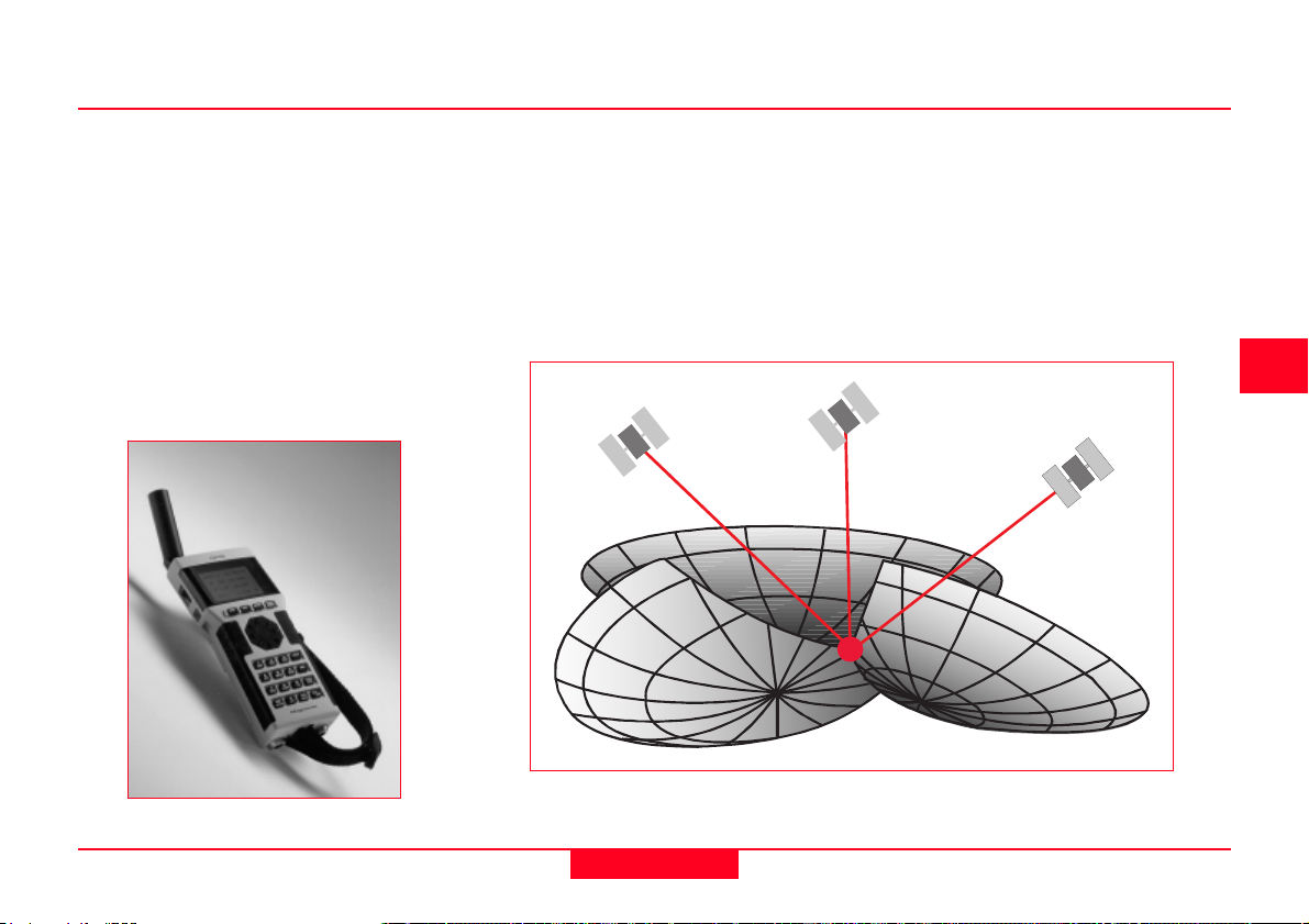
All GPS positions are based on measuring the distance from the satellites to the
GPS receiver on the earth. This distance to each satellite can be determined by the
GPS receiver. The basic idea is that of resection, which many surveyors use in their
daily work. If you know the distance to three points relative to your own position, you
can determine your own position relative to those three points. From the distance to
one satellite we know that the position of the receiver must be at some point on the
surface of an imaginary sphere which has its origin at the satellite. By intersecting
three imaginary spheres the receiver position can be determined.
4
5
6
A Handheld GPS Receiver
GPS Basics -1.0.0en
Intersection of three imaginary spheres
11
How GPS works
Page 12
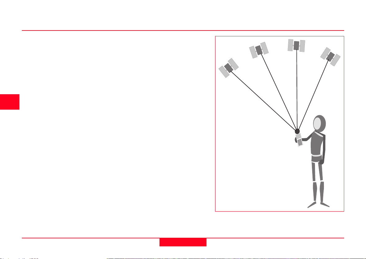
The problem with GPS is that only
pseudoranges and the time at which the
signal arrived at the receiver can be
determined.
Thus there are four unknowns to determine; position (X, Y, Z) and time of travel
of the signal. Observing to four satellites
produces four equations which can be
solved, enabling these unknowns to be
determined.
At least four satellites are required to obtain a
position and time in 3 dimensions
How GPS works
12
GPS Basics -1.0.0en
Page 13
3.1.2 Calculating the distance to the satellite
In order to calculate the distance to each
satellite, one of Isaac Newtons laws of
motion is used:
Distance = Velocity x Time
For instance, it is possible to calculate
the distance a train has traveled if you
know the velocity it has been travelling
and the time for which it has been
travelling at that velocity.
GPS requires the receiver to calculate
the distance from the receiver to the
satellite.
The Velocity is the velocity of the radio
signal. Radio waves travel at the speed
of light, 290,000 km per second
(186,000 miles per second).
The Time is the time taken for the radio
signal to travel from the satellite to the
GPS receiver. This is a little harder to
calculate, since you need to know when
the radio signal left the satellite and
when it reached the receiver.
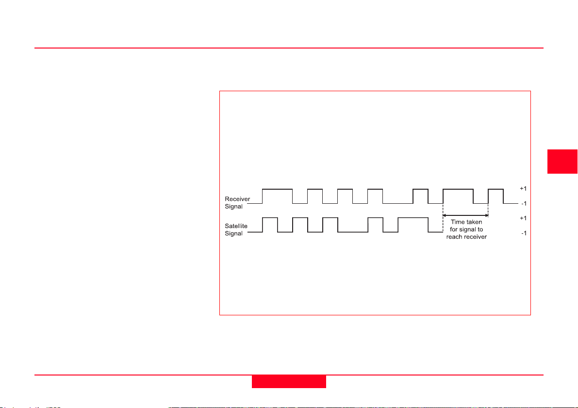
Calculating the Time
The satellite signal has two codes modulated upon it, the C/A code and the
P-code (see section 2.1). The C/A code is based upon the time given by a
very accurate atomic clock. The receiver also contains a clock that is used to
generate a matching C/A code. The GPS receiver is then able to match or
correlate the incoming satellite code to the receiver generated code.
The C/A code is a digital code that is pseudo random or appears to be
random. In actual fact it is not random and repeats one thousand times
every second.
In this way, the time taken for the radio signal to travel from the satellite to
the GPS receiver is calculated.
4
5
6
GPS Basics -1.0.0en
13
How GPS works
Page 14
3.1.3 Error Sources
Up until this point, it has been assumed
that the position derived from GPS is very
accurate and free of error, but there are
several sources of error that degrade the
GPS position from a theoretical few
metres to tens of metres. These error
sources are:
1. Ionospheric and atmospheric
delays
2. Satellite and Receiver Clock
Errors
3. Multipath
4. Dilution of Precision
5. Selective Availability (S/A)
6. Anti Spoofing (A-S)
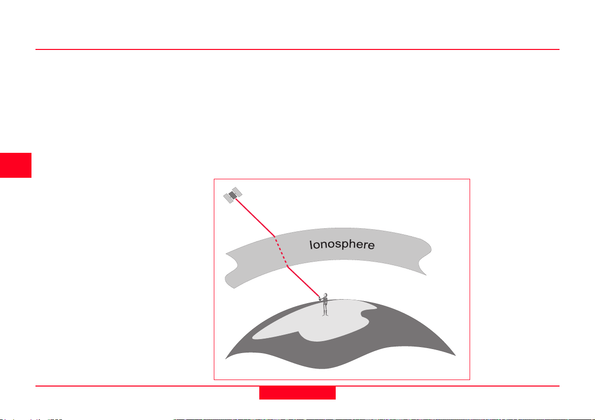
1. Ionospheric and Atmospheric delays
As the satellite signal passes through
the ionosphere, it can be slowed down,
the effect being similar to light refracted
through a glass block. These atmospheric delays can introduce an error in
the range calculation as the velocity of
the signal is affected. (Light only has a
constant velocity in a vacuum).
The ionosphere does not introduce a
constant delay on the signal. There are
several factors that influence the amount
of delay caused by the ionosphere.
How GPS works
14
GPS Basics -1.0.0en
Page 15
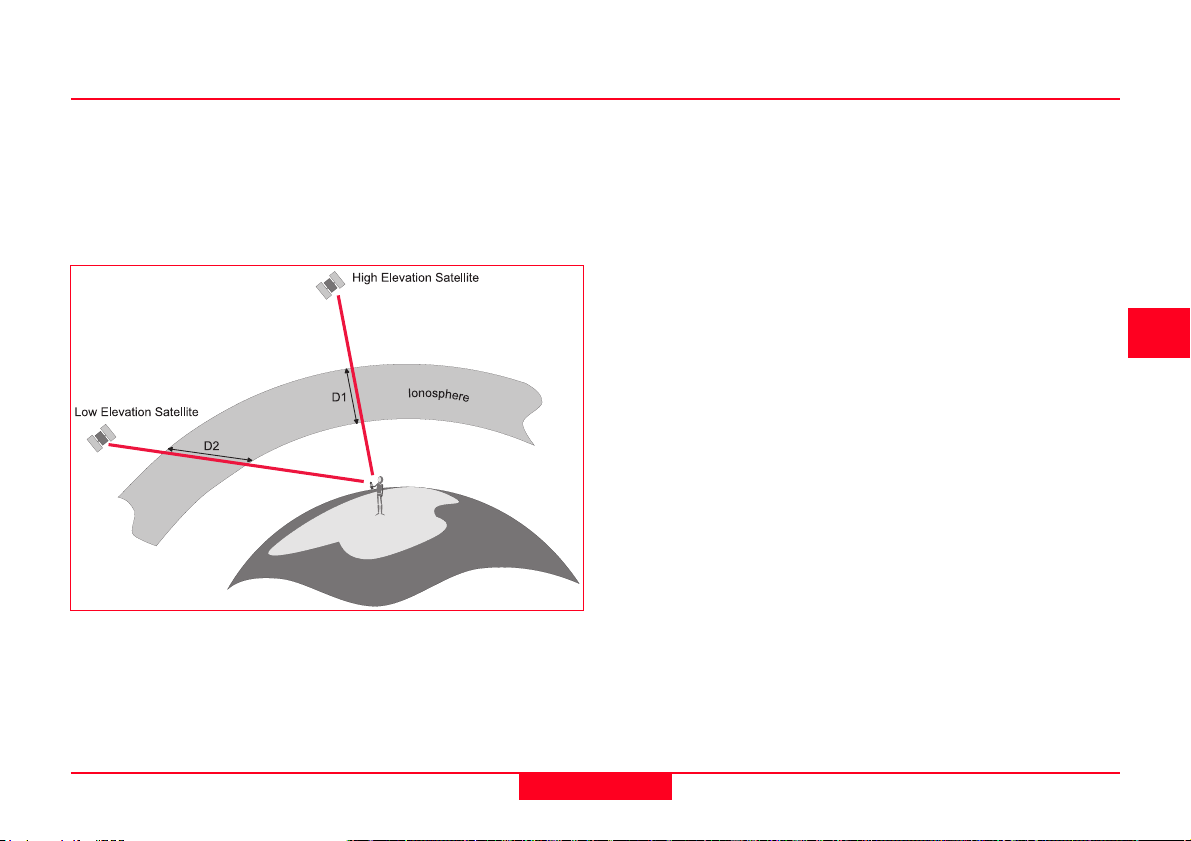
a. Satellite elevation. Signals from low
elevation satellites will be affected more
than signals from higher elevation
satellites. This is due to the increased
distance that the signal passes through
the atmosphere.
b. The density of the ionosphere is
affected by the sun. At night, there is
very little ionospheric influence. In the
day, the sun increases the effect of the
ionosphere and slows down the signal.
The amount by which the density of the
ionosphere is increased varies with
solar cycles (sunspot activity).
Sunspot activity peaks approximately
every 11 years. At the time of writing, the
next peak (solar
max) will be
around the year
2000.
In addition to this,
solar flares can
also randomly
occur and also
have an effect on
the ionosphere.
Ionospheric errors
can be mitigated
by using one of
two methods:
- The first method
involves taking an
average of the
effect of the reduction in velocity of light
caused by the ionosphere. This correction factor can then be applied to the
range calculations. However, this relies
on an average and obviously this
average condition does not occur all of
the time. This method is therefore not
the optimum solution to Ionospheric
Error mitigation.
- The second method involves using
dual-frequency GPS receivers. Such
receivers measure the L1 and the L2
frequencies of the GPS signal. It is
known that when a radio signal travels
through the ionosphere it slows down at
a rate inversely proportional to its
frequency. Hence, if the arrival times of
the two signals are compared, an
accurate estimation of the delay can be
made. Note that this is only possible
with dual frequency GPS receivers. Most
receivers built for navigation are single
frequency.
c. Water Vapour also affects the GPS
signal. Water vapor contained in the
atmosphere can also affect the GPS
signal. This effect, which can result in a
position degradation can be reduced by
using atmospheric models.
4
5
6
GPS Basics -1.0.0en
15
How GPS works
Page 16
2. Satellite and Receiver clock errors
3. Multipath Errors
Even though the clocks in the satellite
are very accurate (to about 3 nanoseconds), they do sometimes drift slightly
and cause small errors, affecting the
accuracy of the position. The US Department of Defense monitors the satellite
clocks using the Control Segment (see
section 2.2) and can correct any drift that
is found.
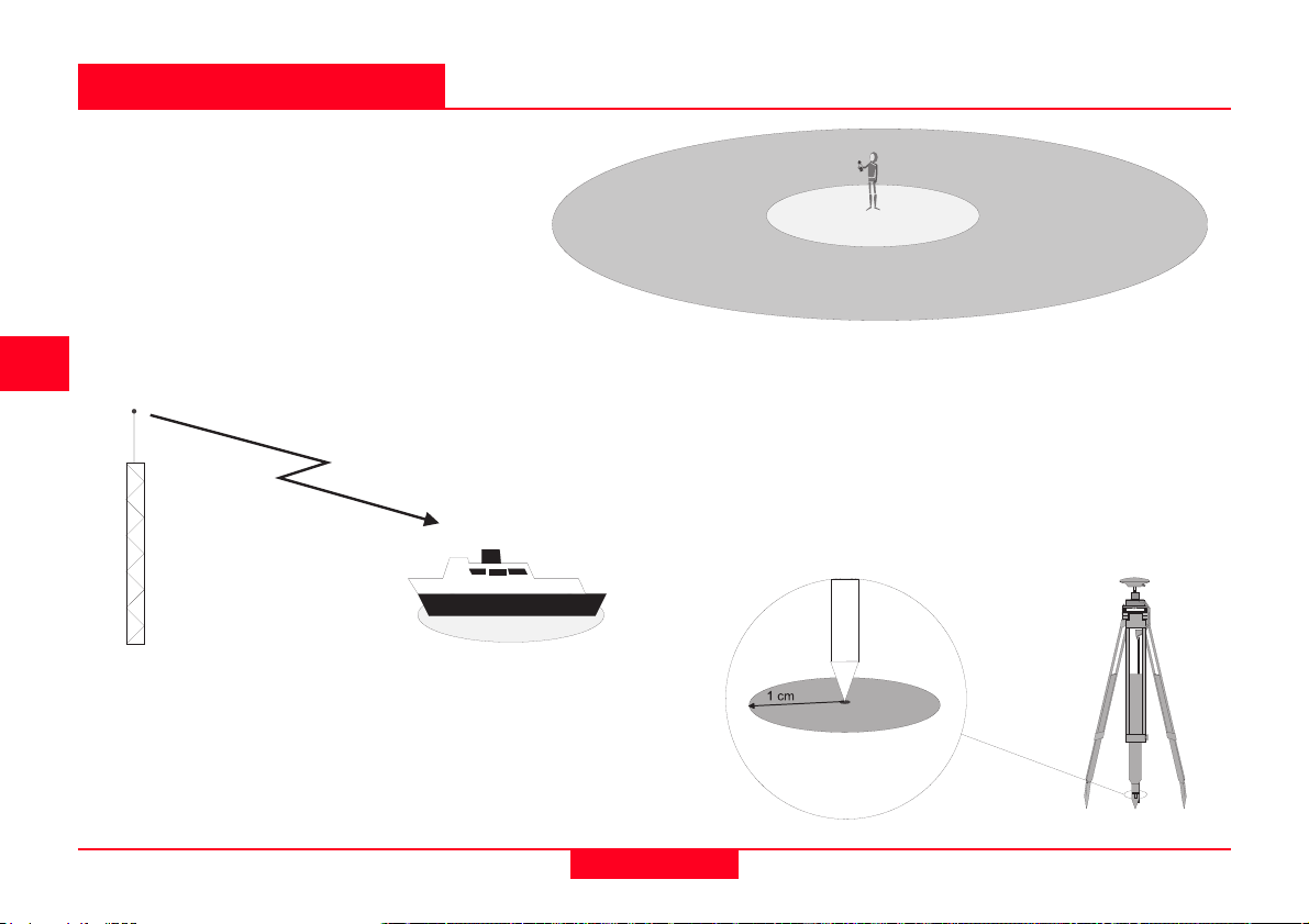
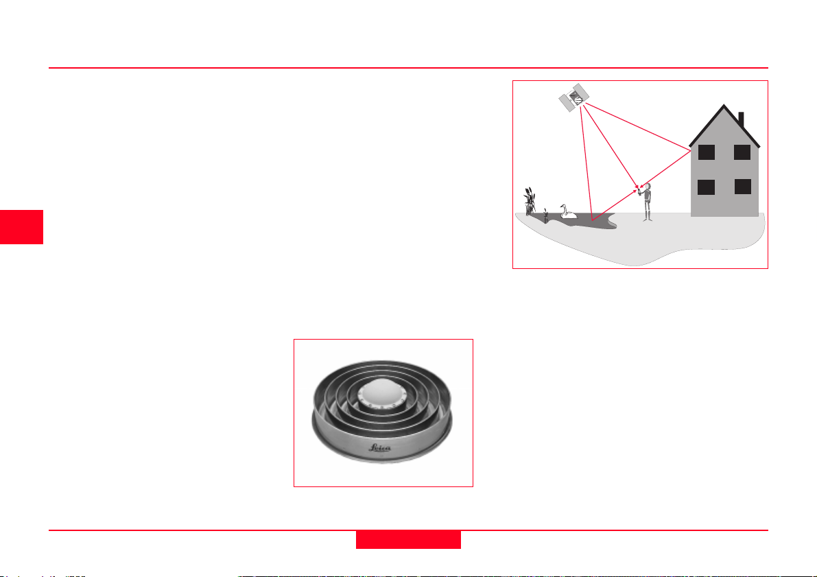
Multipath occurs when the receiver
antenna is positioned close to a
large reflecting surface such as a
lake or building. The satellite signal
does not travel directly to the antenna
but hits the nearby object first and is
reflected into the antenna creating a
false measurement.
Multipath can be reduced by use of
special GPS antennas that incorporate a ground plane (a circular,
metallic disk about 50cm (2 feet) in
diameter) that prevent low elevation
signals reaching the antenna.
Choke-Ring Antenna
For highest accuracy, the preferred solution is
use of a choke ring antenna. A choke ring
antenna has 4 or 5 concentric rings around
the antenna that trap any indirect signals.
Multipath only affects high accuracy, surveytype measurements. Simple handheld
navigation receivers do not employ such
techniques.
How GPS works
16
GPS Basics -1.0.0en
Page 17
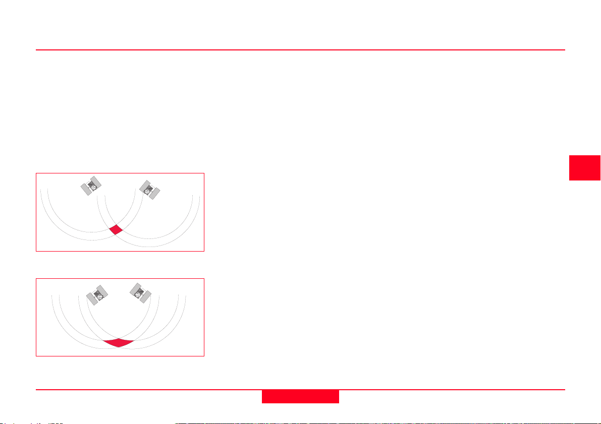
4. Dilution of Precision
The Dilution of Precision (DOP) is a
measure of the strength of satellite
geometry and is related to the spacing
and position of the satellites in the sky.
The DOP can magnify the effect of
satellite ranging errors.
The principle can be best illustrated by
diagrams:
Well spaced satellites - low uncertainty
of position
Poorly spaced satellites - high
uncertainty of position
The range to the satellite is affected by
range errors previously described. When
the satellites are well spaced, the
position can be determined as being
within the shaded area in the diagram
and the possible error margin is small.
When the satellites are close together,
the shaded area increases in size,
increasing the uncertainty of the position.
Different types of Dilution of Precision or
DOP can be calculated depending on
the dimension.
VDOP Vertical Dilution of Precision. Gives accuracy degradation in vertical direction.
HDOP Horizontal Dilution of Precision. Gives accuracy degradation in horizontal direction.
PDOP Positional Dilution of Precision. Gives accuracy degradation in 3D position.
GDOP Geometric Dilution of Precision. Gives accuracy degradation in 3D position and time.
The most useful DOP to know is GDOP
since this is a combination of all the
factors. Some receivers do however
calculate PDOP or HDOP which do not
include the time component.
The best way of minimizing the effect of
GDOP is to observe as many satellites
as possible. Remember however, that
the signals from low elevation satellites
are generally influenced to a greater
degree by most error sources.
As a general guide, when surveying with
GPS it is best to observe satellites that
are 15° above the horizon. The most
accurate positions will generally be
computed when the GDOP is low,
(usually 8 or less).
4
5
6
GPS Basics -1.0.0en
17
How GPS works
Page 18
3.1.4 Why are military receivers more accurate ?
5. Selective Availability (S/A)
Selective Availability is a process
applied by the U.S. Department of
Defense to the GPS signal. This is
intended to deny civilian and hostile
foreign powers the full accuracy of GPS
by subjecting the satellite clocks to a
process known as dithering which
alters their time slightly. Additionally, the
ephemeris (or path that the satellite will
follow) is broadcast as being slightly
different from what it is in reality. The end
result is a degradation in position
accuracy.
It is worth noting that S/A affects civilian
users using a single GPS receiver to
obtain an autonomous position. Users
of differential systems are not significantly affected by S/A.
Currently, it is planned that S/A will be
switched off by 2006 at the latest.
6. Anti-Spoofing (A-S)
Anti-Spoofing is similar to S/A in that its
intention is to deny civilian and hostile
powers access to the P-code part of the
GPS signal and hence force use of the
C/A code which has S/A applied to it.
Anti-Spoofing encrypts the P-code into a
signal called the Y-code. Only users with
military GPS receivers (the US and its
allies) can de-crypt the Y-code.
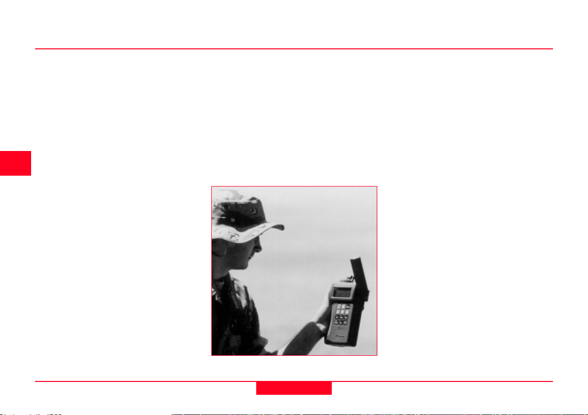
Military receivers are more accurate
because they do not use the C/A code to
calculate the time taken for the signal to
reach the receiver. They use the P-code.
The P-code is modulated onto the carrier
wave at 10.23 Hz. The C/A code is
modulated onto the carrier wave at 1.023
Hz. Ranges can be calculated far more
accurately using the P-code as this code
is occurring 10 times as often as the C/A
code per second.
The P-code is often subjected to Anti
Spoofing (A/S) as described in the last
section. This means that only the
military, equipped with special GPS
receivers can read this encryted P-code
(also known as the Y-code).
For these reasons, users of military GPS
receivers usually get a position with an
accuracy of around 5m whereas, civilian
users of comparable GPS receivers will
only get between about 15-100m
position accuracy.
How GPS works
A military handheld GPS receiver
(courtesy Rockwell)
18
GPS Basics -1.0.0en
Page 19
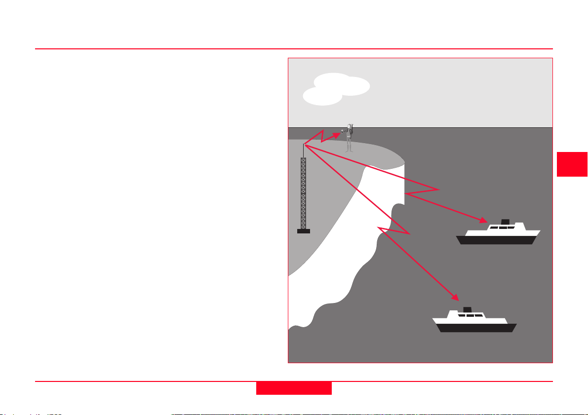
3.2 Differentially corrected positions (DGPS)
Many of the errors affecting the measurement of satellite range can be completely eliminated or at least significantly
reduced using differential measurement
techniques.
DGPS allows the civilian user to increase position accuracy from 100m to
2-3m or less, making it more useful for
many civilian applications.
4
5
6
GPS Basics -1.0.0en
DGPS Reference station broadcasting to Users
19
How GPS works
Page 20

3.2.1 The Reference Receiver
3.2.2 The Rover receiver
3.2.3 Further details
The Reference receiver antenna is
mounted on a previously measured
point with known coordinates. The
receiver that is set at this point is known
as the Reference Receiver or Base
Station.
The receiver is switched on and begins
to track satellites. It can calculate an
autonomous position using the techniques mentioned in section 3.1.
Because it is on a known point, the
reference receiver can estimate very
precisely what the ranges to the various
satellites should be.
The reference receiver can therefore
work out the difference between the
computed and measured range values.
These differences are known as corrections.
The reference receiver is usually attached to a radio data link which is used
to broadcast these corrections.
The rover receiver is on the other end of
these corrections. The rover receiver has
a radio data link attached to it that
enables it to receive the range corrections broadcast by the Reference
Receiver.
The Rover Receiver also calculates
ranges to the satellites as described in
section 3.1. It then applies the range
corrections received from the Reference.
This lets it calculate a much more
accurate position than would be possible if the uncorrected range measurements were used.
Using this technique, all of the error
sources listed in section 3.1.3 are
minimized, hence the more accurate
position.
It is also worthwhile to note that multiple
Rover Receivers can receive corrections
from one single Reference.
DGPS has been explained in a very
simple way in the preceding sections. In
real life, it is a little more complex than
this.
One large consideration is the radio link.
There are many types of radio link that
will broadcast over different ranges and
frequencies. The performance of the
radio link depends on a range of factors
including:
Frequency of the radio
Power of the radio
Type and gain of radio antenna
Antenna position
Networks of GPS receivers and powerful
radio transmitters have been established, broadcasting on a maritime
only safety frequency. These are known
as Beacon Transmitters. The users of
this service (mostly marine craft navigating in coastal waters) just need to
purchase a Rover receiver that can
receive the beacon signal. Such systems have been set up around the
coasts of many countries.
How GPS works
20
GPS Basics -1.0.0en
Page 21

Other devices such as mobile telephones can also be used for transmission of data.
In addition to Beacon Systems, other
systems also exist that provide coverage
over large land areas operated by
commercial, privately owned companies.
There are also proposals for government owned systems such as the
Federal Aviation Authoritys satellitebased Wide Area Augmentation System
(WAAS) in the United States, the European Space Agencys (ESA) system and
a proposed system from the Japanese
government.
There is a commonly used standard for
the format of broadcast GPS data. It is
called RTCM format. This stands for
Radio Technical Commission Maritime
Services, an industry sponsored nonprofit organisation. This format is
commonly used all over the world.
4
5
6
GPS Basics -1.0.0en
21
How GPS works
Page 22

3.3 Differential Phase GPS and Ambiguity Resolution
3.3.1 The Carrier Phase, C/A and P-codes
Differential Phase GPS is used mainly in
surveying and related industries to
achieve relative positioning accuracies
of typically 5-50mm (0.25-2.5 in). The
technique used differs from previously
described techniques and involves a lot
of statistical analysis.
It is a differential technique which means
that a minimum of two GPS receivers are
always used simultaneously. This is one
of the similarities with the Differential
Code Correction method described in
section 3.2.
The Reference Receiver is always
positioned at a point with fixed or known
coordinates. The other receiver(s) are
free to rove around. Thus they are known
as Rover Receivers. The baseline(s)
between the Reference and Rover
receiver(s) are calculated.
The basic technique is still the same as
with the techniques mentioned previously, - measuring distances to four
satellites and computing a position from
those ranges.
The big difference comes in the way
those ranges are calculated.
At this point, it is useful to define the various components of the GPS signal.
Carrier Phase. The sine wave of the L1 or L2 signal that is created by the satellite.
The L1 carrier is generated at 1575.42MHz, the L2 carrier at 1227.6 MHz.
C/A code. The Coarse Acquisition code. Modulated on the L1 Carrier at 1.023MHz.
P-code. The precise code. Modulated on the L1 and L2 carriers at 10.23 MHz.
Refer also to the diagram in section 2.1.
What does modulation mean ?
The carrier waves are designed to carry the binary C/A and P-codes in a process
known as modulation. Modulation means the codes are superimposed on the
carrier wave. The codes are binary codes. This means they can only have the values
1 or -1. Each time the value changes, there is a change in the phase of the carrier.
Carrier Modulation
How GPS works
22
GPS Basics -1.0.0en
Page 23

3.3.2 Why use Carrier Phase?
3.3.3 Double Differencing
The carrier phase is used because it
can provide a much more accurate
measurement to the satellite than using
the P-code or the C/A code. The L1
carrier wave has a wavelength of 19.4
cm. If you could measure the number of
wavelengths (whole and fractional parts)
there are between the satellite and
receiver, you have a very accurate range
to the satellite.
The majority of the error incurred when
making an autonomous position comes
from imperfections in the receiver and
satellite clocks. One way of bypassing
this error is to use a technique known as
Double Differencing.
If two GPS receivers make a measurement to two different satellites, the clock
offsets in the receivers and satellites
cancel, removing any source of error that
they may contribute to the equation.
4
5
6
GPS Basics -1.0.0en
Double Differencing
23
How GPS works
Page 24

3.3.4 Ambiguity and Ambiguity Resolution
After removing the clock errors by double
differencing, the whole number of carrier
wavelengths plus a fraction of a wavelength between the satellite and receiver
antenna can be determined. The
problem is that there are many sets of
possible whole wavelengths to each
observed satellite. Thus the solution is
ambiguous. Statistical processes can
resolve this ambiguity and determine the
most probable solution.
The following explanation is an outline of
how the ambiguity resolution process
works. Many complicating factors are not
covered by this explanation but it does
provide a useful illustration.
Differential code can be used to obtain
1.
2.
an approximate
position. The
precise answer
must lie somewhere
within this circle.
The wavefronts from
a single satellite
strike both within
and outside of the
circle. The precise
point must lie
somewhere on one
of the lines formed
by these wavefronts
inside the circle.
Continued...
When a second
satellite is observed,
How GPS works
24
GPS Basics -1.0.0en
Page 25

3.
5.
4
4.
a second set of
wavefronts or phase
lines are created.
The point must lie
on one of the
intersections of the
two sets of phase
lines.
Adding a third
satellite further
narrows the number
of possibilities. The
point must be on an
intersection of all
three phase lines.
Adding a fourth
6.
satellite further
narrows the
number of
possibilities.
As the satellite
constellation
changes it will
tend to rotate
around one point,
revealing the
most probable
solution.
5
6
GPS Basics -1.0.0en
25
How GPS works
Page 26

4. Geodetic Aspects
Since GPS has become increasingly
popular as a Surveying and Navigation
instrument, surveyors and navigators
require a basic understanding of how
GPS positions relate to standard
mapping systems.
A common cause of errors in GPS
surveys is the result of incorrectly
understanding these relationships.
Geodetic Aspects
26
GPS Basics -1.0.0en
Page 27

4.1 Introduction
Determining a position with GPS
achieves a fundamental goal of Geodesy
- the determination of absolute position
with uniform accuracy at all points on the
earths surface. Using classical geodetic
and surveying techniques, determination
of position is always relative to the
starting points of the survey, with the
accuracy achieved being dependent on
the distance from this point. GPS
therefore, offers a significant advantage
over conventional techniques.
The science of Geodesy is basic to GPS,
and, conversely, GPS has become a
major tool in Geodesy. This is evident if
we look at the aims of Geodesy:
1. Establishment and maintenance of
national and global three-dimensional
geodetic control networks on land,
recognizing the time-varying nature of
these networks due to plate movement.
2. Measurement and representation of
geodynamic phenomena (polar motion,
earth tides, and crustal motion).
3. Determination of the gravity field of the
earth including temporal variations.
Although most users may never carry out
any of the above tasks, it is essential that
users of GPS equipment have a general
understanding of Geodesy.
GPS Basics -1.0.0en
27
Geodetic Aspects
Page 28

4.2. The GPS coordinate system
P
0
X
Y
Z
D
Y
D
Z
D
X
Although the earth may appear to be a
uniform sphere when viewed from
space, the surface is far from uniform.
Due to the fact that GPS has to give
coordinates at any point on the earths
surface, it uses a geodetic coordinate
system based on an ellipsoid. An
ellipsoid (also known as a spheroid) is a
sphere that has been flattened or
squashed.
An ellipsoid is chosen that most accurately approximates to the shape of the
earth. This ellipsoid has no physical
surface but is a mathematically defined
surface.
An Ellipsoid
Geodetic Aspects
There are actually many different ellipsoids or mathematical definitions of the
earths surface, as will be discussed
later. The ellipsoid used by GPS is
known as WGS84 or World Geodetic
System 1984.
A point on the surface of the earth (note
that this is not the surface of the ellipsoid), can be defined by using Latitude,
Longitude and ellipsoidal height.
An alternative method for defining the
position of a point is the Cartesian
Coordinate system, using distances in
the X, Y, and Z axes from the origin or
centre of the spheroid. This is the
method primarily used by GPS for
defining the location of a point in space.
28
Earth's Surface
Height
Latitude
Longitude
Defining coordinates of P by
Geodetic and Cartesian coordinates
GPS Basics -1.0.0en
Page 29

4.3 Local coordinate systems
Just as with GPS coordinates, local
coordinates or coordinates used in a
particular countrys maps are based on
a local ellipsoid, designed to match the
geoid (see section 4.4) in the area.
Usually, these coordinates will have
been projected onto a plane surface to
provide grid coordinates (see section
4.5).
The ellipsoids used in most local
coordinate systems throughout the world
were first defined many years ago,
before the advent of space techniques.
These ellipsoids tend to fit the area of
interest well but could not be applied to
other areas of the earth. Hence, each
country defined a mapping system/
reference frame based on a local
ellipsoid.
When using GPS, the coordinates of the
calculated positions are based on the
WGS84 ellipsoid. Existing coordinates
are usually in a local coordinate system
and therefore the GPS coordinates have
to be transformed into this local system.
WGS84 Ellipsoid
The relationship between ellipsoids
and the earths surface
Earth's Surface
(topography)
Local Ellipsoid
GPS Basics -1.0.0en
29
Geodetic Aspects
Page 30

4.4 Problems with height
The nature of GPS also affects the
measurement of height.
All heights measured with GPS are
given in relation to the surface of the
WGS84 ellipsoid. These are known as
Ellipsoidal Heights.
Existing heights are usually orthometric
heights measured relative to mean sea
level.
Mean sea level corresponds to a
surface known as the geoid. The Geoid
can be defined as an equipotential
surface, i.e. the force of gravity is a
constant at any point on the geoid.
The geoid is of irregular shape and
does not correspond to any ellipsoid.
The density of the earth does however
have an effect on the geoid, causing it to
rise in the more dense regions and fall
in less dense regions.
The relationship between the geoid,
ellipsoid and earths surface is shown
in the graphic below.
As most existing maps show
orthometric heights (relative to the
geoid), most users of GPS also require
their heights to be orthometric.
Geodetic Aspects
This problem is solved by using geoidal
models to convert ellipsoidal heights to
orthometric heights. In relatively flat
areas the geoid can be considered to be
constant. In such areas, use of certain
transformation techniques can create a
height model and geoidal heights can
be interpolated from existing data.
P
H
h
N
h = H+N
where
h = Ellipsoidal Height
H = Orthometric Height
N = Geoid Separation
Relationship between Orthometric
and Ellipsoidal height
30
Topography
Ellipsoid
Geoid
GPS Basics -1.0.0en
Page 31

4.5 Transformations
The purpose of a transformation is to
transform coordinates from one system
to another.
Several different Transformation approaches exist. The one that you use will
depend on the results you require.
The basic field procedure for determination of transformation parameters is the
same no matter which approach is
taken.
Firstly, coordinates must be available in
both coordinate systems (i.e. in WGS84
and in the local system) for at least three
(and preferably four) common points.
The more common points you include in
the transformation, the more opportunity
you have for redundancy and error
checking.
Common points are achieved by measuring points with GPS, where the
coordinates and orthometric heights are
known in the local system, (e.g. existing
control points).
The transformation parameters can then
be calculated using one of the transformation approaches.
It is important to note that the transformation will only apply to points in the
area bounded by the common points.
Points outside of this area should not be
transformed using the calculated
parameters but should form part of a
new transformation area.
Transformations apply within an area of
common points
GPS Basics -1.0.0en
31
Geodetic Aspects
Page 32

Helmert Transformations
The Helmert 7 parameter transformation
offers a mathematically correct transformation. This maintains the accuracy of
the GPS measurements and local
coordinates.
Experience has shown that it is common
for GPS surveys to be measured to a
much higher accuracy than older surveys
measured with traditional optical
instruments.
In the vast majority of cases, the previously measured points will not be as
accurate as the new points measured
with GPS. This may create non-homogeneity in the network.
When transforming a point between
coordinate systems, it is best to think of
the origin from which the coordinates are
derived as changing and not the surface
on which it lies.
In order to transform a coordinate from
one system to another, the origins and
axes of the ellipsoid must be known
relative to each other. From this information, the shift in space in X, Y and Z from
one origin to the other can be deter-
mined, followed by any rotation about the
X, Y and Z axes and any change in scale
between the two ellipsoids.
Z
S
w
Z
T
X
L
Y
S
= Position in WGS84
P
S
P
X
S
wX,
= Position in Local System
L
T
= Resultant Vector from shift of origin in X, Y and Z
wY,
w
Z
= Rotation angles
7 parameter Helmert transformation
P
Z
L
P
S
P
L
Y
w
w
X
L
Y
Local
Ellipsoid
WGS84
Ellipsoid
Geodetic Aspects
32
GPS Basics -1.0.0en
Page 33

Other transformation approaches
Whilst the Helmert transformation
approach is mathematically correct, it
cannot account for irregularities in the
local coordinate system and for accurate
heighting, the geoid separation must be
known.
Therefore, Leica also makes a number
of other transformation approaches
available in its equipment and software.
The so-called Interpolation approach does not rely on knowledge of the local ellipsoid or map projection.
Inconsistencies in the local coordinates
are dealt with by stretching or squeezing
any GPS coordinates to fit homogeneously in the local system.
Additionally a height model can be
constructed. This compensates for lack
of geoid separations, provided sufficient
control points are available.
As an alternative to the Interpolation approach the One Step approach may be used. This transformation approach also works by treating the height and position transformations separately. For the position transformation, the WGS84
GPS Basics -1.0.0en
coordinates are projected onto a temporary Transverse Mercator projection and
then the shifts, rotation and scale from
the temporary projection to the "real"
projection are calculated. The Height
transformation is a single dimension
height approximation.
This transformation may be used in
areas where the local ellipsoid and map
projection are unknown and where the
geoid is reasonably constant.
Point projected onto
height model surface
Height model generated from 4 known points
33
Both the Interpolation and the One Step
approach should be limited to an area of
about 15 x 15km, (10 x 10 miles).
A combination of the Helmert and Interpolation approaches may be found in the Stepwise approach. This approach uses a 2D Helmert transformation to obtain position and a height interpolation to obtain heights. This approach requires the knowledge of local ellipsoid and map projection.
Height model
Ellipsoidal surface
Orthometric height
at common point
Geodetic Aspects
Page 34

4.6 Map Projections and Plane Coordinates
Most Surveyors measure and record
coordinates in an orthogonal grid
system. This means that points are
defined by Northings, Eastings and
orthometric height (height above sea
level). Map Projections allow surveyors
to represent a 3 dimensional curved
surface on a flat piece of paper.
0 102030405060708090100110 N
0 102030405060708090100110 E
A plane grid based map The basic idea behind map projections
Such map projections appear as planes
but actually define mathematical steps
for specifying positions on an ellipsoid
in the terms of a plane.
The way in which a map projection
generally works is shown in the diagram. Points on the surface of the
a'
a
b
o
spheroid are projected on to a plane
surface from the origin of the spheroid.
The diagram also highlights the problem
that it is not possible to represent true
lengths or shapes on such a plane. True
lengths are only represented where the
plane cuts the spheroid (points c and g).
b'
c
d
d'
e'
e
f
f'
g
h'
h
i'
i
Geodetic Aspects
34
GPS Basics -1.0.0en
Page 35

4.6.1 The Transverse Mercator Projection
The Transverse Mercator projection is a
conformal projection. This means that
angular measurements made on the
projection surface are true.
The Projection is based on a cylinder
that is slightly smaller than the spheroid
and is then flattened out. The method is
used by many countries and is especially suited to large countries around
the equator.
The Transverse Mercator Projection is
defined by:
False Easting and False Northing.
Latitude of Origin
Central Meridian
Scale on Central meridian
Zone Width
Cylinder
Transverse Mercator projection
Spheroid
GPS Basics -1.0.0en
35
Geodetic Aspects
Page 36

The False Easting and False Northing
are defined in order that the origin of the
grid projection can be in the lower left
hand corner as convention dictates. This
does away with the need for negative
coordinates.
The Latitude of Origin defines the
Latitude of the axis of the cylinder. This is
normally the equator (in the northern
hemisphere).
The Central Meridian defines the
direction of grid north and the longitude
of the centre of the projection.
Scale varies in an east-west direction. As
the cylinder is usually smaller than the
spheroid, the Scale on Central Meridian
is too small, is correct on the ellipses of
intersection and is then too large at the
edges of the projection.
The scale in the north-south direction
does not vary. For this reason, the
Transverse Mercator projection is most
suitable for mapping areas that are long
in the north-south direction.
The Zone Width defines the portion of
the spheroid in an east-west direction to
which the projection applies.
N
0
Features of the Transverse Mercator projection
Zone Width
Central Meridian
Ellipses of
Intersection
E
Universal Transverse Mercator (UTM)
The UTM projection covers the world between 80ºN and 80ºS latitude. It is a
type of Transverse Mercator projection, with many of the defining parameters
held fixed. The UTM is split into zones of 6º longitude with adjacent zones
overlapping by 30. The one defining parameter is the Central Meridian or
Zone Number. (When one is defined, the other is implied).
Geodetic Aspects
36
GPS Basics -1.0.0en
Page 37

4.6.2 The Lambert Projection
The Lambert Projection is also a
conformal projection based on a cone
that intersects the spheroid. It is ideal for
small, circular countries, islands and
polar regions.
Cone
Spheroid
The Lambert Projection
The Lambert projection is defined by:
False Easting and Northing
Latitude of origin
Central Meridian
Latitude of 1st Standard
Parallel
Latitude of 2nd Standard Parallel
The False Easting and
False Northing are
defined in order that the
origin of the grid projection can be in the lower
left hand corner as
convention dictates. This
does away with the need
for negative coordinates.
The Latitude of Origin
defines the latitude of the
origin of the projection.
The Central Meridian
defines the direction of
grid north and the
longitude of the centre of
the projection.
The Latitude of 1st
Standard Parallel
defines the latitude at
which the cone first cuts
the spheroid. This also
defines where the
N
Width
1/6 Zone
Zone Width
0
Features of the Lambert Projection
2/3 Zone Width
Width
1/6 Zone
Standard Parallel
Central Meridian
Standard Parallel
E
influence of scale in the north-south direction is zero.
The Latitude of 2nd Standard Parallel defines the
second latitude at which the cone cuts the pyramid. The
influence of scale will also be zero at this point.
The scale is too small between the standard parallels
and too large outside them, being defined by the
latitudes of the Standard Parallels at which it is zero.
Scale in the east-west direction does not vary.
GPS Basics -1.0.0en
37
Geodetic Aspects
Page 38

5. Surveying with GPS
Probably even more important to the
surveyor or engineer than the theory
behind GPS, are the practicalities of the
effective use of GPS.
Like any tool, GPS is only as good as its
operator. Proper planning and preparation are essential ingredients of a
successful survey, as well as an awareness of the capabilities and limitations
of GPS.
Why use GPS?
GPS has numerous advantages over
traditional surveying methods:
1. Intervisibility between points is not
required.
2. Can be used at any time of the day or
night and in any weather.
3. Produces results with very high
geodetic accuracy.
4. More work can be accomplished in
less time with fewer people.
Limitations
In order to operate with GPS it is important that the GPS Antenna has a clear
view to at least 4 satellites. Sometimes,
the satellite signals can be blocked by
tall buildings, trees etc. Hence, GPS
cannot be used indoors. It is also
difficult to use GPS in town centers or
woodland.
Due to this limitation, it may prove more
cost effective in some survey applications to use an optical total station or to
combine use of such an instrument with
GPS.
Clear view to four satellites
Surveying with GPS
38
Large objects can block the GPS signal
GPS Basics -1.0.0en
Page 39

5.1 GPS Measuring Techniques
There are several measuring techniques
that can be used by most GPS Survey
Receivers. The surveyor should choose
the appropriate technique for the application.
Static - Used for long lines, geodetic networks, tectonic plate studies etc. Offers high accuracy over long distances but is comparatively slow.
Rapid Static - Used for establishing local control networks, Network densification etc. Offers high accuracy on baselines up to about 20km and is much faster than the Static technique.
Kinematic - Used for detail surveys and measuring many points in quick succession. Very efficient way of measuring many points that are close together. However, if there are obstructions to the sky such as bridges, trees, tall buildings etc., and less than 4 satellites are tracked, the equipment must be reinitialized which can take 5-10 minutes.
A processing technique known as Onthe-Fly (OTF) has gone a long way to
minimise this restriction.
RTK - Real Time Kinematic uses a radio
data link to transmit satellite data from
the Reference to the Rover. This enables
coordinates to be calculated and
displayed in real time, as the survey is
being carried out. Used for similar
applications as Kinematic. A very effective way for measuring detail as results
are presented as work is carried out.
This technique is however reliant upon a
radio link, which is subject to interference from other radio sources and also
line of sight blockage.
GPS Basics -1.0.0en
39
Surveying with GPS
Page 40

5.1.1 Static Surveys
This was the first method to be developed for GPS surveying. It can be used
for measuring long baselines (usually
20km (16 miles) and over).
One receiver is placed on a point whose
coordinates are known accurately in
WGS84. This is known as the Reference
Receiver. The other receiver is placed on
the other end of the baseline and is
known as the Rover.
Data is then recorded at both stations
simultaneously. It is important that data
is being recorded at the same rate at
each station. The data collection rate
may be typically set to 15, 30 or 60
seconds.
The receivers have to collect data for a
certain length of time. This time is
influenced by the length of the line, the
number of satellites observed and the
satellite geometry (dilution of precision
or DOP). As a rule of thumb, the observation time is a minimum of 1 hour for a
20km line with 5 satellites and a
prevailing GDOP of 8. Longer lines
require longer observation times.
Once enough data has been collected,
the receivers can be switched off. The
Rover can then be moved to the next
baseline and measurement can once
again commence.
It is very important to introduce redundancy into the network that is being
measured. This involves measuring
points at least twice and creates safety
checks against problems that would
otherwise go undetected.
A great increase in productivity can be
realized with the addition of an extra
Rover receiver. Good coordination is
required between the survey crews in
order to maximize the potential of having
three receivers. An example is given on
the next page.
Surveying with GPS
40
GPS Basics -1.0.0en
Page 41

1
2
3
The network ABCDE has to be
measured with three receivers. The
coordinates of A are known in
WGS84. The receivers are placed on
A, B and C. GPS data is recorded for
the required length of time.
4
Finally, B moves back to C and the
line EC is measured.
GPS Basics -1.0.0en
After the required length of time, the
receiver that was at E moves to D
and B moves to C. The triangle ACD
is measured.
5
The end result is the measured
network ABCDE. One point is measured three times and every point has
been measured at least twice. This
provides redundancy. Any gross errors
will be highlighted and the offending
measurement can be removed.
41
Then A moves to E and C moves to
B. The triangle BDE is measured.
Surveying with GPS
Page 42

5.1.2 Rapid Static Surveys
In Rapid Static surveys, a Reference
Point is chosen and one or more Rovers
operate with respect to it.
Typically, Rapid Static is used for
densifying existing networks, establishing control etc.
When starting work in an area where no
GPS surveying has previously taken
place, the first task is to observe a
number of points, whose coordinates
are accurately known in the local system.
This will enable a transformation to be
calculated and all hence, points measured with GPS in that area can be
easily converted into the local system.
As discussed in section 4.5, at least 4
known points on the perimeter of the
area of interest should be observed. The
transformation calculated will then be
valid for the area enclosed by those
points.
The Reference Receiver is usually set
up at a known point and can be included
in the calculations of the transformation
parameters. If no known point is available, it can be set up anywhere within
the network.
The Rover receiver(s) then visit each of
the known points. The length of time that
the Rovers must observe for at each
point is related to the baseline length
from the Reference and the GDOP.
The data is recorded and post-processed back at the office.
Checks should then be carried out to
ensure that no gross errors exist in the
measurements. This can done by
measuring the points again at a different
time of the day.
When working with two or more Rover
receivers, an alternative is to ensure that
all rovers operate at each occupied point
simultaneously. Thus allows data from
each station to be used as either
Reference or Rover during postprocessing and is the most efficient way
to work, but also the most difficult to
synchronise.
Another way to build in redundancy is to
set up two reference stations, and use
one rover to occupy the points as shown
in the lower example on the next page.
Surveying with GPS
42
GPS Basics -1.0.0en
Page 43

1
2
3
4
5
The network 1,2,3,4,5
has to be measured
from Reference
station R with three
GPS receivers.
Alternatively...
1
Reference stations
are set up at R and
point 1. The Rover
occupies point 2.
GPS Basics -1.0.0en
The reference station
is set up. One Rover
occupies point 1
whilst the other
occupies point 3.
After the required
length of time, the
Rover moves to point
3.
After the required
length of time, one
Rover moves to point
2 whilst the other
moves to point 4.
Similarly, the Rover
then progresses to
point 4...
43
Then, one Rover can
return to the office
whilst the other
measures point 5.
The end result is as
above. On a subsequent day, the operation will be repeated
in order to check for
gross errors.
4532
...and then point 5. The end result is a
measured network
with built-in redundancy.
Surveying with GPS
Page 44

5.1.3 Kinematic Surveys
The Kinematic technique is typically
used for detail surveying, recording
trajectories etc., although with the advent
of RTK its popularity is diminishing.
The technique involves a moving Rover
whose position can be calculated
relative to the Reference.
Firstly, the Rover has to perform what is
known as an initialization. This is
essentially the same as measuring a
Rapid Static point and enables the postprocessing software to resolve the
ambiguity when back in the office. The
Reference and Rover are switched on
and remain absolutely stationary for 5-20
minutes, collecting data. (The actual
time depends on the baseline length
from the Reference and the number of
satellites observed).
After this period, the Rover may then
move freely. The user can record positions at a predefined recording rate, can
record distinct positions, or record a
combination of the two. This part of the
measurement is commonly called the
kinematic chain.
1 2 3
Initialization is performed
from the Reference to the
Rover.
A major point to watch during kinematic
surveys is to avoid moving too close to
objects that could block the satellite
signal from the Rover receiver. If at any
time, less than four satellites are tracked
by the Rover receiver, you must stop,
move into a position where 4 or more
satellites are tracked and perform an
initialization again before continuing.
The Rover can then move.
Positions can be recorded
at a predefined interval...
Kinematic on the Fly
This is a variation of the Kinematic
technique and overcomes the requirement of initializing and subsequent reinitialization when the number of
observed satellites drops below four.
Kinematic on the Fly is a processing
method that is applied to the measurement during post-processing. At the
start of measurement, the operator can
simply begin walking with the Rover
receiver and record data. If they walk
under a tree and lose the satellites,
upon emerging back into satellite
coverage, the system will automatically
reinitialize.
...and also at distinct
points if required.
Surveying with GPS
44
GPS Basics -1.0.0en
Page 45

5.1.4 RTK Surveys
RTK stands for Real Time Kinematic. It
is a Kinematic on the Fly survey carried
out in real time.
The Reference Station has a radio link
attached and rebroadcasts the data it
receives from the satellites.
The Rover also has a radio link and
receives the signal broadcast from the
Reference. The Rover also receives
satellite data directly from the satellites
via its own GPS Antenna. These two
sets of data can be processed together
at the Rover to resolve the ambiguity and
therefore obtain a very accurate position
relative to the Reference receiver.
Once the Reference Receiver has been
set up and is broadcasting data through
the radio link, the Rover Receiver can be
activated.
When it is tracking satellites and receiving data from the Reference, it can begin
the initialization process. This is similar
to the initialization performed in a postprocessed kinematic on the fly survey,
the main difference being that it is
carried out in real-time.
Once the initialization is complete, the
ambiguities are resolved and the Rover
can record point and coordinate data. At
this time, baseline accuracies will be in
the 1 - 5cm range.
It is important to maintain contact with
the Reference Receiver, otherwise the
Rover may lose the ambiguity. This
results in a far less accurate position
being calculated.
Additionally, problems may be encountered when surveying close to obstructions such as tall buildings, trees etc. as
the satellite signal may be blocked.
RTK is quickly becoming the most
common method of carrying out high
precision, high accuracy GPS surveys in
small areas and can be used for similar
applications as a conventional total
station. This includes detail surveying,
stakeout, COGO applications etc.
The Radio Link
Most RTK GPS systems make use of
small UHF radio modems. Radio
communication is the part of the RTK
system that most people experience
difficulty with. It is worth considering the
following influencing factors when trying
to optimize radio performance:
1. Power of the transmitting radio.
Generally speaking, the more power, the
better the performance. However, most
countries legally restrict output power to
0.5 - 2W.
2. Height of transmitter antenna. Radio
communication can be affected by line of
sight. The higher up you can position the
antenna, the less likely you are to get
line of sight problems. It will also
increase the overall range of radio
communication. The same also applies
to the receiving antenna.
Other influencing factors affecting
performance include the length of the
cable to radio antenna (longer cables
mean higher losses) and the type of
radio antenna used.
GPS Basics -1.0.0en
45
Surveying with GPS
Page 46

5.2 Pre-survey preparation
5.3 Tips during operation
Before heading out into the field, the
surveyor needs to prepare for the survey.
Items that must be considered are:
1. Radio Licences
2. Power - charged batteries
3. Spare cables
4. Communication between survey
parties
5. Coordinates of Reference Station
6. Memory cards - Do you have enough
spare memory?
7. Observation schedule. First objective
should be to get enough information
for determination of Transformation
Parameters, then aim for redundancy
of observations.
For Static and Rapid Static surveys,
always fill out a record sheet for each
point you survey. An example is given on
the next page.
With Static and Rapid Static surveys, it is
vital that the antenna height is measured
correctly. This is one of the most common mistakes when carrying out a GPS
survey. Measure the height at the
beginning and end of occupation. With
Kinematic and RTK Surveys, the antenna is usually mounted on a pole
which has a constant height.
During Static and Rapid Static surveys,
the GPS antenna has to be kept totally
still. This also applies to the Rapid Static
initialization of Kinematic surveys (but
not to Kinematic on the Fly or RTK
surveys). Any movement or vibration in
the antenna can adversely affect the
result.
Surveying with GPS
46
GPS Basics -1.0.0en
Page 47

Field Sheet
Point Id
Sensor Serial No
Operation Type
Antenna Type
Height Reading
Start Time
Stop Time
No. of Epochs
No. of Satellites
GDOP
GPS Basics -1.0.0en
Date
Operator
47
Notes
Surveying with GPS
Page 48

Glossary
Almanac
Library of coarse satellite orbital data
used to calculate satellite position, rise
time, elevation, and azimuth.
Ambiguity
The unknown integer number of cycles
of the reconstructed carrier phase
contained in an unbroken set of measurements from a single satellite pass
at a single receiver.
Anti-spoofing (A-S)
Encrypting the P-code (to form the Ycode).
Atmospheric propagation delay
Time delay affecting satellite signals due
to tropospheric layers of the earths
atmosphere.
Azimuth
A horizontal angle measured clockwise
from a direction (such as North).
Bandwidth
A measure of the width of the spectrum
of a signal (frequency domain representation of a signal) expressed in Hertz.
Baseline
The length of the three-dimensional
vector between a pair of stations for
which simultaneous GPS data has been
collected and processed with differential
techniques.
Bearing
Term used in navigation to describe the
angle between a reference direction
(e.g., geographic north, magnetic north,
grid north) and the trajectory.
Beat frequency
Either of the two additional frequencies
obtained when signals of two frequencies are mixed. The beat frequencies
are equal to the sum or difference of the
original frequencies, respectively.
Binary biphase modulation
Phase changes of either 0° or 180° (to
represent binary 0 or 1, respectively) on
a constant frequency carrier. These can
be modelled by
y = A cos (wt + p),
where the amplitude function A is a
sequence of +1 and -1 values (to
represent 0° and 180° phase changes
respectively). GPS signals are biphase
modulated.
Glossary
48
GPS Basics -1.0.0en
Page 49

C/A code
The Coarse/Acquisition GPS code
modulated on the GPS L1 signal. This
code is a sequence of 1023 pseudorandom binary biphase modulations on the
GPS carrier at a chipping rate of 1.023
MHz, thus having a code repetition
period of one millisecond.
Cartesian Coordinates
The coordinates of a point in space
given in three mutually perpendicular
dimensions (x, y, z) from the origin.
Carrier
A radio wave having at least one characteristic (e.g., frequency, amplitude,
phase) which may be varied from a
known reference value by modulation.
Carrier beat phase
The phase of the signal which remains
when the incoming Doppler-shifted
satellite carrier signal is beat (the
difference frequency signal is generated)
with the nominally constant reference
frequency generated in the receiver.
Carrier frequency
The frequency of the unmodulated
fundamental output of a radio transmitter. The GPS L1 carrier frequency is
1575.42 MHz, the GPS L2 carrier frequency is 1227.60 MHz.
Chip
The time interval of either a zero or a one
in a binary pulse code
Chip rate
Number of chips per second (e.g., C/A
code : 1.023*10
Clock offset
Constant difference in the time reading
of two clocks.
6
cps)
Code
A system used for communication in
which arbitrarily chosen strings of zeros
and ones are assigned definite meanings.
Compacted data
Raw data compacted over a specified
time interval (compaction time) into one
single observable (measurement) for
recording.
Conformal Projection
A map projection that preserves angles
on the ellipsoid after they have been
mapped onto the plane.
Control segment
Ground-based GPS System equipment
operated by the U.S. Government that
tracks the satellite signals, determines
the orbits of the satellites, and transmits
orbit definitions to the memories of the
satellites.
GPS Basics -1.0.0en
49
Glossary
Page 50

Cutoff angle
The minimum elevation angle below
which no more GPS satellites are
tracked by the sensor.
Cycle slip
A discontinuity of an integer number of
cycles in the measured carrier beat
phase resulting from a temporary loss of
lock of a GPS satellite signal.
Data message
A message included in the GPS signal
that reports the satellites location, clock
corrections, and health. Included is
rough information on the status of other
satellites in the constellation.
DGPS
Differential GPS. The term commonly
used for a GPS system that utilizes
differential code corrections to achieve
an enhanced positioning accuracy of
around 0.5 - 5m.
Deflection of the vertical
The angle between the normal to the
ellipsoid and the vertical (true plumb
line). It is usually resolved into a component in the meridian and a component
perpendicular to the meridian.
Delay lock
The technique whereby the received
code (generated by the satellite clock) is
compared with the internal code (generated by the receiver clock) and the latter
shifted in time until the two codes match.
Differenced measurements
GPS measurements can be differenced
across receivers, across satellites and
across time. Although many combinations are possible, the present convention for GPS phase measurement
differencing is to perform the differences
in the above order: first across receivers, second across satellites and third
across time.
A
single difference measurement
(across receivers) is the instantaneous
difference in phase of a received signal,
measured by two receivers simultaneously observing one satellite.
A
double difference measurement
(across receivers and satellites) is
obtained by differencing the single
difference for one satellite with respect to
the corresponding single difference for a
chosen reference satellite.
triple difference measurement (across
A
receivers, satellites and time) is the
difference between a double difference
at one epoch of time and the same
double difference at another epoch of
time.
Differential positioning
Determination of relative coordinates
between two or more receivers which
are simultaneously tracking the same
GPS signals.
Glossary
50
GPS Basics -1.0.0en
Page 51

Dilution of precision (DOP)
A description of the purely geometrical
contribution to the uncertainty in a
position fix. The DOP factor indicates the
geometrical strength of the satellite
constellation at the time of measurement. Standard terms in the case of
GPS are
Eccentricity
The ratio of the distance from the centre
of an ellipse to its focus to the
semimajor axis.
e = (1 - b
where a and b are the semimajor and
semiminor axis of the ellipse, respectively.
2/a2)1/2
Ellipsoid height
The vertical distance of a point above the
ellipsoid.
Ephemeris
A list of positions or locations of a
celestial object as a function of time.
GDOP three position coordinates plus
clock offset
PDOP three coordinates
HDOP two horizontal coordinates
VDOP height only
TDOP clock offset only
HTDOP horizontal position and time
Doppler shift
The apparent change in frequency of a
received signal due to the rate of change
of the range between the transmitter and
receiver.
GPS Basics -1.0.0en
Elevation
Height above the Geoid. See
Orthometric height.
Ellipsoid
In geodesy, unless otherwise specified,
a mathematical figure formed by revolving an ellipse about its minor axis
(sometimes also referred to as spheroid). Two quantities define an ellipsoid;
these are usually given as the length of
the semimajor axisa and the flatteningf.
51
Ephemeris error
Difference between the actual satellite
location and the location predicted by the
satellite orbital data (ephemerides).
Epoch
A particular fixed instant of time used as
a reference point on a time scale.
Equipotential Surface
A mathematically defined surface where
the gravitational potential is the same at
any point on that surface. An example of
such a surface is the geoid.
Glossary
Page 52

Flattening
Relating to Ellipsoids.
f = (a-b)/a = 1-(1-e2)
where a ... semimajor axis
b ... semiminor axis
e ... eccentricity
Fundamental frequency
The fundamental frequency used in GPS
is 10.23MHz. The carrier frequencies L1
and L2 are integer multiples of the
fundamental frequency.
1/2
Geocentric
Relating to the centre of the earth.
Geodesy
The study of the earths size and shape
Geodetic Coordinates
Coordinates defining a point with
reference to an ellipsoid. Geodetic
Coordinates are either defined using
latitude, longitude and ellipsoidal height
or using Cartesian coordinates.
deflection of the vertical at the origin, and
the geodetic azimuth of a line from the
origin to some other point.
Geoid
The particular equipotential surface
which coincides with mean sea level,
and which may be imagined to extend
through the continents. This surface is
everywhere perpendicular to the direction of the force of gravity.
Geoidal Height
See Geoid separation
L1 = 154F = 1575.42 MHz
L2 = 120F = 1227.60 MHz
GDOP
Geometric dilution of precision
> Dilution of precision
Glossary
Geodetic Datum
A mathematical model designed to best
fit part or all of the geoid. It is defined by
an ellipsoid and the relationship between the ellipsoid and a point on the
topographic surface established as the
origin of datum. This relationship can
be defined by six quantities, generally
(but not necessarily) the geodetic
latitude, longitude, and the height of the
origin, the two components of the
52
Geoid separation
The distance from the surface of the
reference ellipsoid to the geoid measured outward along the normal to the
ellipsoid.
GPS
Global Positioning System
GPS Basics -1.0.0en
Page 53

GPS time
A continuous time system based on the
Coordinated Universal Time (UTC) from
6th January 1980.
Greenwich mean time (GMT)
The mean solar time of the meridian of
Greenwich. Used as the prime basis of
standard time throughout the world.
Great circle course
Term used in navigation. Shortest
connection between two points.
Graticule
A plane grid representing the lines of
Latitude and Longitude of an ellipsoid.
Inclination
The angle between the orbital plane of
an object and some reference plane
(e.g., equatorial plane).
Integer bias term
See Ambiguity
Ionospheric Delay
A wave propagating through the ionosphere (which is a non-homogeneous
and dispersive medium) experiences
delay. Phase delay depends on electron
content and affects carrier signals.
Group delay depends on dispersion in
the ionosphere as well, and affects
signal modulation (codes). The phase
and group delay are of the same magnitude but opposite sign.
Keplerian orbital elements
Allow description of any astronomical
orbit:
a: semimajor axis
e: eccentricity
w: argument of perigee
W: right ascension of ascend
ing node
i: inclination
n: true anomaly
Lambert Projection
A conformal conic map projection that
projects an ellipsoid onto a plane
surface by placing a cone over the
sphere.
Gravitational constant
The proportionality constant in Newtons
Law of gravitation.
G = 6.672 * 10
-11 m3s-2kg-1
GPS Basics -1.0.0en
Kinematic positioning
Determination of a time series of sets of
coordinates for a moving receiver, each
set of coordinates being determined
from a single data sample, and usually
computed in real time.
53
Latitude
The angle between the ellipsoidal
normal and the equatorial plane.
Latitude is zero on the equator and 90°
at the poles.
Glossary
Page 54

L-band
The radio frequency band extending from
390 MHz to 1550 MHz. The frequencies
of the L1 and L2 carriers transmitted by
GPS satellites lie within this L-band.
Least squares estimation
The process of estimating unknown
parameters by minimizing the sum of the
squares of measurement residuals.
Local Ellipsoid
An Ellipsoid that has been defined for
and fits a specific portion of the earth.
Local ellipsoids usually fit single or
groups of countries.
Local Time
Local time equals to GMT time + time
zone.
Longitude
Longitude is the angle between the
meridian ellipse which passes through
Greenwich and the meridian ellipse
containing the point in question. Thus,
Latitude is 0° at Greenwich and then
measured either eastward through 360°
or eastward 180° and westward 180°.
Meridian
An imaginary line joining north to south
pole and passing through the equator at
90°.
Multipath error
A positioning error resulting from
interference between radio waves which
have travelled between the transmitter
and the receiver by two paths of different
electrical lengths.
NAVSTAR
Acronym for Navigation System with
Time and Ranging, the original name for
GPS.
NMEA
National Marine Electronics Association.
Defined a standard (NMEA 0183) to
enable marine electronics instruments,
communication and navigation equipment to communicate. This standard is
used to get time and position data out of
GPS instruments in many applications.
Observing Session
A period of time over which GPS data is
collected simultaneously by two or more
receivers.
Orthometric height
The distance of a point above the geoid
measured along the plumb line through
the point (height above mean sea level).
See also Elevation.
Glossary
54
GPS Basics -1.0.0en
Page 55

P-code
The Precise GPS code - a very long
(about 10
dom binary biphase modulations on the
GPS carrier at a chipping rate of 10.23
MHz which does not repeat itself for
about 267 days. Each one-week
segment of the P-code is unique to one
GPS satellite, and is reset each week.
Access to the P-code will be restricted by
the U.S. Government to authorized users
only.
PDOP
Position dilution of precision.
see Dilution of Precision
Phase observable
See Reconstructed Carrier Phase
Point Positioning
The independent reduction of observations made by a particular receiver using
the pseudorange information broadcast
from the satellites.
14
bit) sequence of pseudoran-
GPS Basics -1.0.0en
Post processing
The process of computing positions in
non-real-time, using data previously
collected by GPS receivers.
Precise positioning service (PPS)
The highest level of point positioning
accuracy provided by GPS. It is based
on the dual-frequency P - code.
Propagation delay
See Atmospheric propagation delay,
and Ionospheric delay
Pseudolite
The ground-based differential GPS
station which transmits a signal with a
structure similar to that of an actual GPS
satellite.
Pseudorandom noise (PRN) code
Any group of binary sequences that
55
appear to be randomly distributed like
noise, but which can be exactly distributed. The most important property of
PRN codes is that the sequence has a
minimum autocorrelation value, except
at zero lag.
Pseudorange
A measure of the apparent signal
propagation time from the satellite to the
receiver antenna, scaled into distance by
the speed of light. The apparent propagation time is the difference between the
time of signal reception (measured in
the receiver time frame) and the time of
emission (measured in the satellite time
frame). Pseudorange differs from the
actual range by the influence of satellite
and user clock.
Range
Term used in Navigation for the length of
the trajectory between two points. The
trajectory is normally the great circle or
the rhumb line.
Glossary
Page 56

Rapid static survey
Term used in connection with the GPS
System for static survey with short
observation times. This type of survey is
made possible by the fast ambiguity
approach that is resident in the SKI
software.
Raw data
Original GPS data taken and recorded
by a receiver.
Receiver channel
The radio frequency and digital hardware and the software in a GPS receiver,
required to track the signal from one
GPS satellite at one of the two GPS
carrier frequencies.
Reconstructed carrier phase
The difference between the phase of the
incoming Doppler-shifted GPS carrier
and the phase of a nominally-constant
reference frequency generated in the
receiver.
Glossary
Relative positioning
See Differential positioning
Rhumb line
Term used in navigation. Trajectory
between two points with constant
bearing.
RINEX
Receiver INdependent EXchange format.
A set of standard definitions and formats
to promote the free exchange of GPS
data
RTCM
Radio Technical Commission for
Maritime services. Commission set up
to define a differential data link to relay
GPS messages from a monitor station
to a field user.
56
RTK
Real Time Kinematic. A term used to
describe the procedure of resolving the
phase ambiguity at the GPS receiver so
that the need for post-processing is
removed.
Satellite Constellation
The arrangement in space of the
complete set of satellites of a system
like GPS.
Satellite Configuration
The state of the satellite constellation at
a specific time, relative to a specific user
or set of users.
Selective availability (SA)
Degradation of point positioning accuracy for civil users by the U.S. Department of Defense. SA is produced by
either clock dithering or orbit degradation.
GPS Basics -1.0.0en
Page 57

Sidereal day
Time interval between two successive
upper transits of the vernal equinox.
Site
A location where a receiver has been
setup to determine coordinates.
Space segment
The part of the whole GPS system that is
in space, i.e. the satellites.
Solar day
Time interval between two successive
upper transits of the Sun.
Squared reception mode
A method used for tracking GPS L2
signals which doubles the carrier
frequency and does not use the P-code.
Squaring-type channel
A GPS receiver channel which multiplies
the received signal by itself to obtain a
second harmonic of the carrier which
does not contain the code modulation.
Standard positioning service (SPS)
Level of point positioning accuracy
provided by GPS based on the singlefrequency C/A - code.
Static Survey
The expression static survey is used in
connection with GPS for all non-kinematic survey applications. This includes
the following operation modes:
Static survey
Rapid static survey
Stop & Go Survey
The term Stop&Go survey is used in
connection with GPS for a special kind of
kinematic survey. After initialization
(determination of ambiguities) on the
first site, the roving receiver has to be
moved between the other sites without
loosing lock to the satellite signal. Only
a few epochs are then necessary on
these sites to get a solution with survey
accuracy. Once loss of lock occurred, a
new initialization has to be done.
Time Zone
Time zone = Local Time - Greenwich
Mean Time (GMT). Note that Greenwich
Mean Time is approximately equal to
GPS time.
Topography
The form of the land of a particular
region.
GPS Basics -1.0.0en
57
Glossary
Page 58

Transformation
The process of transforming coordinates
from one system to another.
Transit
The predecessor to GPS. A satellite
navigation system that was in service
from 1967 to 1996.
Transverse Mercator Projection
A conformal cylindrical map projection
which may be visualized as a cylinder
wrapped around the earth.
Translocation
The method of using simultaneous data
from separate stations to determine the
relative position of one station with
respect to another station. See differential positioning.
Universal time
Local solar mean time at Greenwich
Meridian
UT Abbreviation for universal time
UT0 UT as deduced directly from
observation of stars
UT1 UT0 corrected for polar motion
UT2 UT1 corrected for seasonal
variations in the Earths rotation
rate
UTC Universal Time Coordinated;
uniform atomic time system kept
very close to UT2 by offsets.
User equivalent range error (UERE)
The contribution to the range measurement error from an individual error
source, converted into range units,
assuming that error source is
uncorrelated with all other error sources.
User segment
The part of the GPS system that includes
the receivers of GPS signals.
UTM
Universal Transverse Mercator Projection. A form of Transverse Mercator
projection. The projection has different
zones, each 6° wide with a central scale
factor of 0.996. Which zone is used
depends upon your location on the earth.
Y-code
An encrypted version of the P-code that
is transmitted by a GPS satellite when in
the anti-spoofing mode.
WGS 84
World Geodetic System 1984. The
system on which all GPS measurements and results are based.
Zenith angle
Vertical angle with 0° on the horizon and
90° directly overhead.
Glossary
58
GPS Basics -1.0.0en
Page 59

Further Reading
GPS Theory and Practice B. Hofmann-Wellenhof, H. Lichtenegger and J. Collins.
ISBN 3-211-82839-7 Springer Verlag.
GPS Satellite Surveying Alfred Leick.
ISBN 0471306266 John Wiley and Sons.
Satellite Geodesy: Foundations, Methods and Applications Gunter Seeber.
ISBN 3110127539 Walter De Gruyter.
Understanding GPS: Principles and Applications
Elliot D. Kaplan (Ed.).
ISBN 0890067937 Artech House.
The Global Positioning System: Theory and Applications
Bradford W. Parkinson and James J. Spilker (Eds.).
ISBN 9997863348 American Institute of Aeronautics and Astronautics.
GPS Basics -1.0.0en
59
Further Reading
Glossary
Page 60

Index
A
Almanac 48
Ambiguity 24, 45, 48
Ambiguity Resolution 22, 24
Anti-Spoofing (A-S). See Error Sources
Atmospheric propagation delay 48
Azimuth 48
B
Bandwidth 48
Baseline 48
Bearing 48
Beat frequency 48
Binary biphase modulation 48
C
C/A code 7, 13, 18, 22, 49
Carrier 49
Carrier beat phase 49
Carrier phase 22, 23, 49
Cartesian coordinates 28, 49
Central Meridian 36, 37
Chip 49
Chip rate 49
Choke-Ring Antenna 16
Clock (Satellite and Receiver) 16
Clock offset 49
Code 49
Compacted data 49
Conformal Projection 49
Control segment 8, 49
Coordinate system 28
Cartesian 28, 49
GPS 28
Local 29
Coordinate transformation 31
Helmert 32
Interpolation 33
One Step 33
Stepwise 33
Cutoff angle 50
Cycle slip 50
D
Data message 50
Deflection of the vertical 50
Delay lock 50
DGPS 10, 19, 20, 50
Differenced measurements 50
Differential positioning 50
Differential phase 22
Dilution of precision (DOP) 51
GDOP 17, 51, 52
HDOP 17, 51
HTDOP 51
PDOP 17, 51, 55
TDOP 51
VDOP 17, 51
Distance to satellite 13
Doppler shift 51
Double difference 23, 50
E
Eccentricity 51
Elevation 51
Ellipsoid 28, 51
Ellipsoid height 30, 51
Ephemeris 51
Epoch 51
Equipotential Surface 51
Error Sources 14
Anti-Spoofing (A-S) 18, 48
Dilution of Precision 17, 51
Multipath 16, 54
Satellite and Receiver clock 16
Selective Availability (S/A) 18, 56
Water Vapour 15
F
False Easting 36, 37
False Northing 36, 37
Flattening 52
Fundamental frequency 52
Glossary
60
GPS Basics -1.0.0en
Page 61

G
L
O
GDOP. See Dilution of precision (DOP)
Geocentric 52
Geodesy 52
Geodetic Datum 52
Geoid 52
Geoid separation 30, 33, 52
GPS 52
GPS time 53
Graticule 53
Gravitational constant 53
Great circle cours 53
Greenwich mean time (GMT) 53
H
Helmert Transformation 32
I
Inclination 53
Integer bias term 53
Ionospheric Delay 14, 53
K
Keplerian orbital elements 53
Kinematic 39, 44, 53
Kinematic On the Fly (OTF) 39, 44
L-band 54
Lambert Projection 53
Latitude 28, 53
Latitude of Origin 36, 37
Least squares estimation 54
Longitude 28, 54
M
Map projection 34
Lambert 37
Transverse Mercator 35
Universal Transverse Mercator 36
Measuring techniques (GPS) 39
Kinematic 39, 44
Kinematic On the Fly (OTF) 39, 44
Rapid Static 39, 42
Real Time Kinematic (RTK) 39, 45, 56
Static 39, 40
Meridian 54
Multipath error 54
N
NAVSTAR 5, 54
NMEA 54
Orthometric height 30, 54
P
P-code 55
Phase observable 55
Point Positioning 55
Post processing 55
Precise positioning service (PPS) 55
Projection. See Map projection
Propagation delay 55
Pseudolite 55
Pseudorandom noise (PRN) code 55
Pseudorange 55
R
Radio link 45
Range 55
Rapid Static 39, 42
Rapid static survey 56
Raw data 56
Real Time Kinematic (RTK) 39, 45, 56
Receiver channel 56
Reconstructed carrier phase 56
Reference Receiver 20
Relative positioning 56
Rhumb line 56
RINEX 56
GPS Basics -1.0.0en
61
Glossary
Page 62

Rover receiver 20
RTCM 21, 56
RTK 39, 45, 56
S
Satellite Configuration 56
Satellite Constellation 56
Selective Availability (S/A). See Error
Sources
Sidereal day 57
Site 57
Solar day 57
Space segment 57
Squared reception mode 57
Squaring-type channel 57
Standard Parallel 37
Standard positioning service (SPS) 57
Static 39, 40
Static Survey 57
Stop & Go Survey 57
T
Time Zone 57
Topography 57
Transformation 31, 58
Helmert transformation 32
Interpolation approach 33
One Step approach
Stepwise approach 33
Transit 58
Translocation 58
Transverse Mercator Projection 58
33
U
Universal time 58
User equivalent range error (UERE) 58
User segment 58
UTM 58
W
Water Vapour. See Error Sources
WGS 84 58
Y
Y-code 58
Z
Zenith angle 58
Zone Width 36
Glossary
62
GPS Basics -1.0.0en
Page 63

GPS Basics -1.0.0en
63
Glossary
Page 64

Leica Geosystems AG, Heerbrugg,
Switzerland, has been certified as
being equipped with a quality system
which meets the International Standards of Quality Management and
Quality Systems (ISO standard 9001)
and Environmental Management
Systems (ISO standard 14001).
Total Quality ManagementOur commitment to total customer
satisfaction
Ask your local Leica agent for more
information about our TQM program
713282-1.0.0en
Printed in Switzerland - Copyright Leica
Geosystems AG, Heerbrugg, Switzerland 1999
To get more information on Leica GPS
products visit our homepage:
www.leica-geosystems.com
or contact us directly:
L
Leica Geosystems AG
Heinrich-Wild-Strasse
CH-9435 Heerbrugg
(Switzerland)
Phone +41 71 727 31 31
Fax +41 71 727 47 02
LSGMASTER@leica-geosystems.com
Leica Geosystems Inc.
3155 Medlock Bridge Road
Norcross, GA 30071
(USA)
Phone +1 770 447 6361
Fax +1 770 447 0710
Carson.Kennedy@leica-geosystems.com
 Loading...