

Page 1
Version 1.0
English
Leica GPS1200 PC Simulator
Getting Started
Page 2

Introduction
Purchase Congratulations on the purchase of a GPS1200 PC Simulator with SmartAntenna
(ATX1230/ATX1230 GG) option.
)
Product identification The type and the serial number of your product are indicated on the type plate.
Symbols The symbols used in this manual have the following meanings:
Trademarks • Windows and Windows CE are a registered trademark of Microsoft Corporation
Validity of this manual • This manual applies to the GPS1200 PC Simulator with SmartAntenna option. The
To use the product in a permitted manner, please read carefully throughout this manual
before using the GPS1200 PC Simulator with SmartAntenna option.
Enter the type and serial number in your manual and always refer to this information when
you need to contact your agency or Leica Geosystems authorized service workshop.
Type: _________________________
Serial No.: _________________________
Type Description
)
• Bluetooth is a registered trademark of Bluetooth SIG, Inc
All other trademarks are the property of their respective owners.
steering of the SmartAntenna via GPS1200 PC Simulator is limited to the GX1230 and
GX1230 GG sensor type.
Important paragraphs which must be adhered to in practice as they enable
the product to be used in a technically correct and efficient manner.
Introduction GPS1200 2
Page 3
• This manual covers instructions for setting up the GPS1200 PC Simulator with SmartAntenna option and operating it. Refer to GPS1200 Technical Reference Manual for information about GPS1200 general and applications functionality.
Available documentation
The following documentation for GPS1200 is available:
Name Description Format
User Manual All instructions required in order to operate the
XX
product to a basic level are contained in the
User Manual. Provides an overview of the
product together with technical data and safety
directions.
Name Description Format
System Field Manual Describes the general working of the product in
standard use. Intended as a quick reference
field guide.
X
Introduction GPS1200 3
Page 4

Name Description Format
Application Programs Field
Manual
Describes specific onboard application
programs in standard use. Intended as a quick
XX
reference field guide. The RoadRunner application program is described in a separate manual.
Technical Reference
Manual
Overall comprehensive guide to the product and
program functions. Included are detailed
descriptions of special software/hardware
settings and software/hardware functions
intended for technical specialists.
Refer to the following resources for all GPS1200 documentation and software:
•the SmartWorx DVD
• http://www.leica-geosystems.com/downloads
X
Introduction GPS1200 4
Page 5

Table of Contents
In this manual Chapter Page
1Concept 6
1.1 Introduction 6
1.2 Hardware and software requirements 7
2 Bluetooth Connections 8
2.1 Connecting SmartAntenna to PC 8
2.2 Connecting mobile phone to PC 15
3 Operating the Simulator 19
3.1 Configuring the GPS1200 PC Simulator 19
3.2 Configuring RTK connection 23
3.3 Configuring an Internet connection 27
3.3.1 Configuring Internet interface 27
3.3.2 Configuring a dial-up connection 32
3.4 Accessing GPS data from 3rd party application 48
Appendix A LED indicators on SmartAntenna 49
Index 1
Table of Contents GPS1200 5
Page 6

1Concept
1.1 Introduction
Description The combination of the Leica GPS1200 PC Simulator and the SmartAntenna
(ATX1230/ATX1230 GG) is a lightweight, innovative GNSS rover with RTK capability and the
precision of Leica's high end GPS1200. Different RTK data formats are supported and the
connection can be done as dial-in or via Internet (NTRIP). It is a cable free solution that
allows the user to collect data directly in the field using the power of the Leica GPS1200 PC
Simulator.
Function The Leica GPS1200 PC Simulator with SmartAntenna option allows the steering of the Smar-
tAntenna with a PC via COM port and Bluetooth.
Concept GPS1200 6
Page 7

1.2 Hardware and software requirements
Required hardware The following hardware is required for for steering the SmartAntenna with a PC:
• SmartAntenna (ATX1230/ATX1230 GG)
• Battery GEB211
•Pole
•Dongle
• PC (recommendation: Pentium 1GHz processor or higher / 512 MB RAM or more /
®
Micrsosoft
• Integrated (or external) Bluetooth device to connect the SmartAntenna and the PC
• RTK device with Bluetooth (e.g. mobile phone)
• PC requires a Bluetooth module that supports at least two devices in parallel.
Required software The following software tools are required for steering the SmartAntenna with a PC:
• Leica GPS1200 PC Simulator with SmartAntenna option
• Bluetooth software (e.g. Microsoft)
WindowsTM 2000 or XP / Microsoft® Internet Explorer 5.5 or higher)
Concept GPS1200 7
Page 8
2 Bluetooth Connections
2.1 Connecting SmartAntenna to PC
Connecting SmartAntenna step-by-step
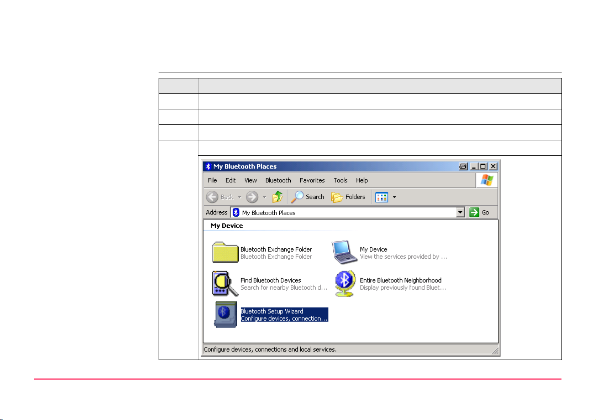
Step Description
1. Insert the battery (GEB211) into SmartAntenna and switch it on.
)
2. Activate Bluetooth on the PC.
3. Open the Bluetooth software and start Bluetooth Setup Wizard.
The following steps can differ from PC to PC.
Bluetooth Connections GPS1200 8
Page 9
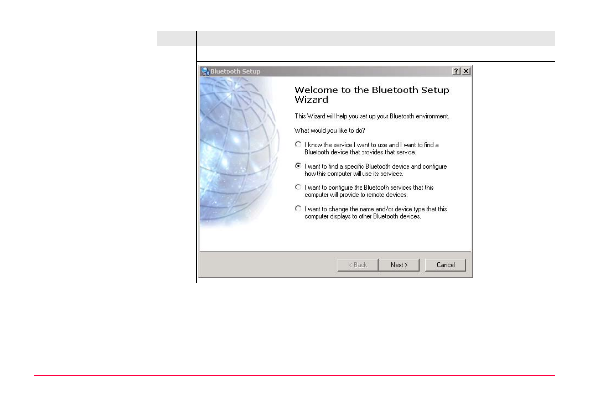
Step Description
4. Select specific Bluetooth device to be configured and click Next.
Bluetooth Connections GPS1200 9
Page 10
Step Description
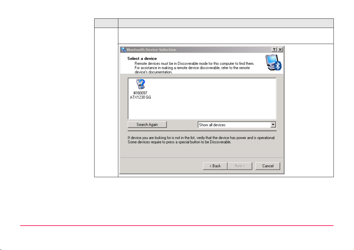
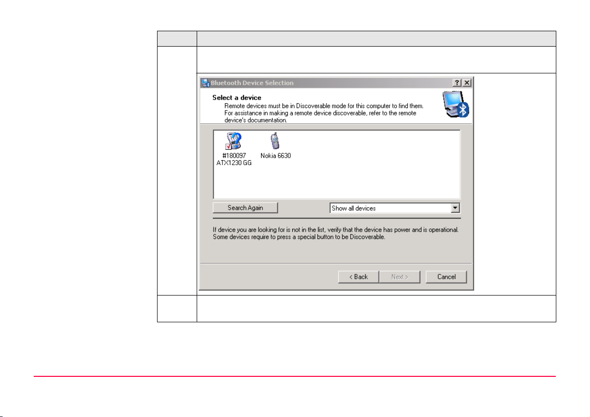
5. The Bluetooth device selection will be started and an automatic search will be
done.
Bluetooth Connections GPS1200 10
Page 11
Step Description
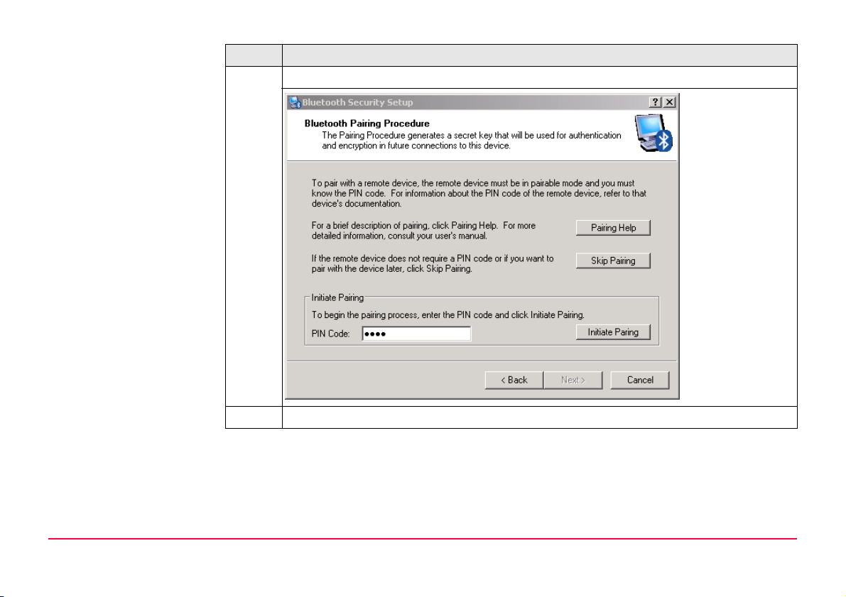
6. Select the shown ATX1230 GG and click Next. The pairing procedure is started.
7. Type in 0000 and click Initiate Paring.
Bluetooth Connections GPS1200 11
Page 12
Step Description
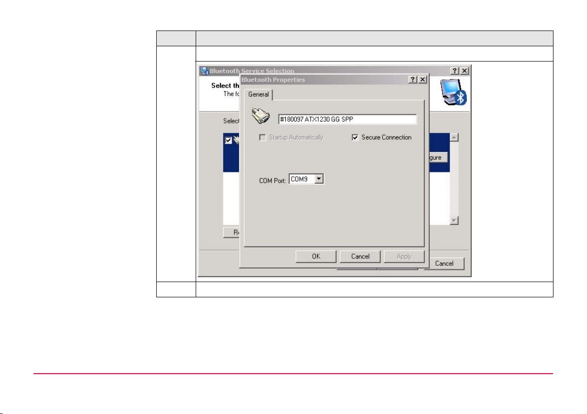
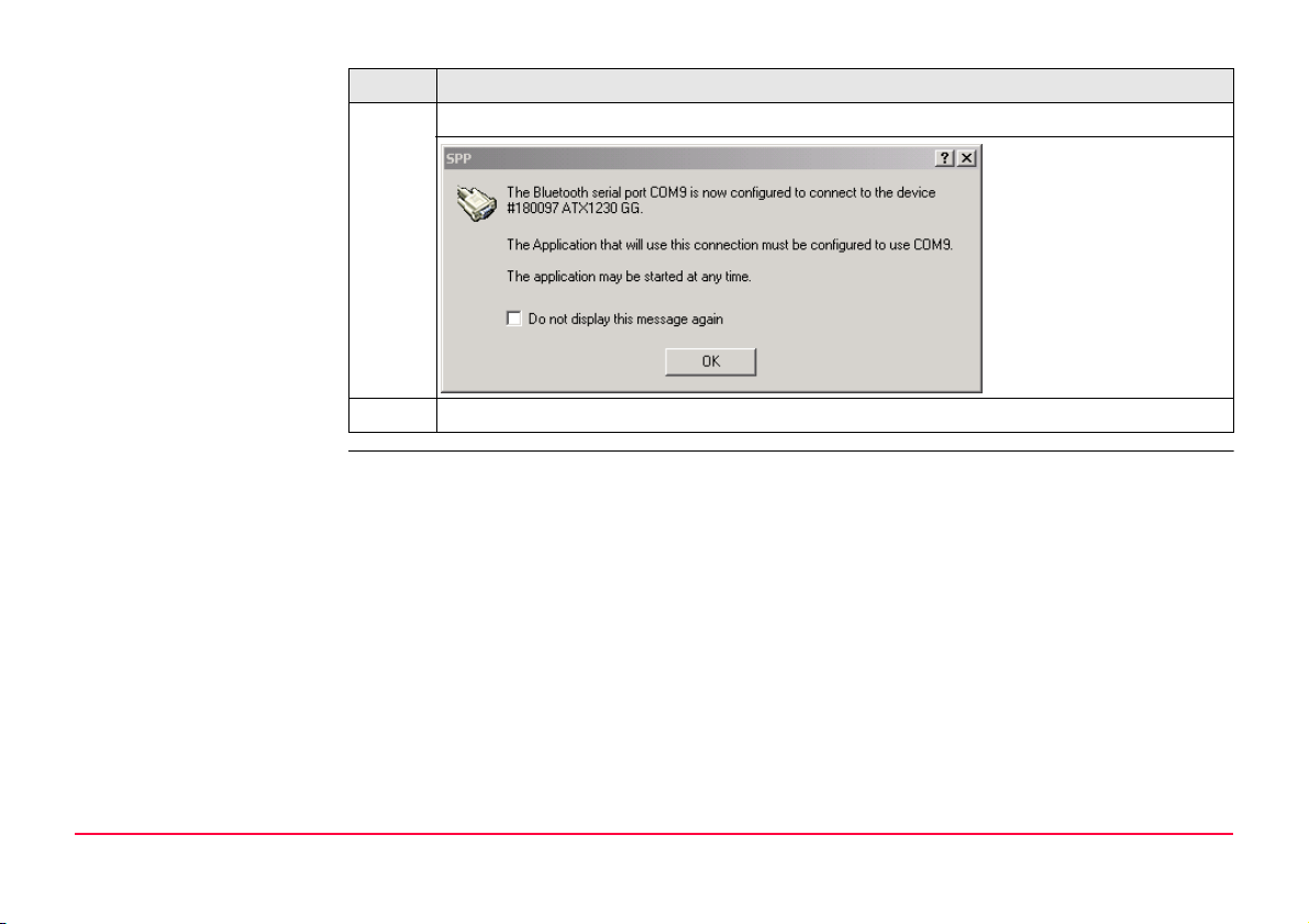
8. Enable SPP and click OK.
9. Click Finish.
Bluetooth Connections GPS1200 12
Page 13
Step Description
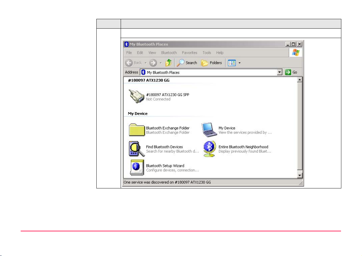
10. A shortcut of the service will be added to My Bluetooth Places on your PC.
Bluetooth Connections GPS1200 13
Page 14
Step Description
11. Right-mouse click on the ATX1230 GG and Connect the antenna.
12. The SmartAntenna is now connected via serial COM9 port.
Bluetooth Connections GPS1200 14
Page 15

2.2 Connecting mobile phone to PC
Connecting mobile
phone step-by-step
Step Description
)
1. Switch the mobile phone on. Activate Bluetooth and make it visible.
2. Start the Bluetooth software on your PC and start Bluetooth Setup Wizard.
3. Choose specific Bluetooth device to be configured and click Next. Refer to"2.1
The necessary steps for connecting a mobile phone to a PC can slightly differ
depending on the model. The following steps are related to a Nokia 6630.
Refer to"2.1 Connecting SmartAntenna to PC".
Connecting SmartAntenna to PC".
Bluetooth Connections GPS1200 15
Page 16
Step Description
4. The Bluetooth device selection will be started and an automatic search will be
done.
5. Select the Nokia 6630 and click Next. The pairing procedure is started. Refer
to"2.1 Connecting SmartAntenna to PC".
Bluetooth Connections GPS1200 16
Page 17

Step Description
6. Type in 0000 and click Initiate Paring. Type in 0000 on your Nokia 6630 and
press OK. The Bluetooth service selection appears on your PC.
Bluetooth Connections GPS1200 17
Page 18

Step Description
7. Enable Dial-Up Networking, click Finish and a shortcout for the selected service
will be added to My Bluetooth Places on your PC.
8. Right-mouse click on the Nokia 6630. Under Properties -> Configure you will find
the configured COM port to be used for the connection to the PC.
Bluetooth Connections GPS1200 18
Page 19

3 Operating the Simulator
3.1 Configuring the GPS1200 PC Simulator
Description This chapter explains the starting of the GPS1200 PC Simulator in general, the configuration
of the sensor type and the COM ports in detail.
Configuring the
GPS1200 PC Simulator
Operating the Simulator GPS1200 19
Step Description
)
Before you can start the GPS1200 PC Simulator you have to install the software
onto your PC. Go to the related folder on the SmartWorx DVD and run the installation.
Page 20

Step Description
1. Start the GPS1200 PC Simulator software.
2. Click Configuration -> COM Ports....
Operating the Simulator GPS1200 20
Page 21

Step Description
3. Select the configured COM port of the Nokia 6630 (COM10) for Port2 and the
configured COM port of the SmartAntenna (COM9) for ATX and click OK.
4. Click Configuration -> Sensor....
5. Select GX1230 GG or GX1230 and click OK.
6. Switch the sensor on by clicking the PROG key on the GPS1200 PC Simulator.
Operating the Simulator GPS1200 21
Page 22

Step Description
Operating the Simulator GPS1200 22
Page 23

3.2 Configuring RTK connection
Overview This chapter explains the settings you have to configure to receive RTK data using a GSM.
)
Configuring RTK
settings
Refer to GPS1200 Technical Reference Manual for detailed information about configuration
of a Rover Real-Time interface using a digital cellular phone.
Step Description
1. Switch the sensor on. Refer to "3.1 Configuring the GPS1200 PC Simulator".
2. Enter CONFIGURE Real-Time Mode.
Operating the Simulator GPS1200 23
Page 24

Step Description
3. Make the following settings:
•R-Time Mode: Rover
• R-Time Data: RTCM 18,19 v2
• Port: Port 2 (port has to be the same as configured in "3.1 Configuring the
GPS1200 PC Simulator")
• Device: Nokia Phone
Settings for Ref Sensor and Ref Antenna depend on your situation.
4. Enter GSM Connection.
Operating the Simulator GPS1200 24
Page 25

Step Description
5. Configure a station to dial and click CONT (F1).
6. Click SHIFT CONEC (F4) to establish the RTK connection.
Operating the Simulator GPS1200 25
Page 26

Step Description
7. The connection will be established and the GPS1200 PC Simulator starts receiciving RTK data.
Operating the Simulator GPS1200 26
Page 27

3.3 Configuring an Internet connection
)
3.3.1 Configuring Internet interface
Configuring Internet
Interface settings
Refer to GPS1200 Technical Reference Manual for detailed information about configuration
of a Rover Real-Time interface using an Internet connection.
Step Description
1. Switch the sensor on. Refer to "3.1 Configuring the GPS1200 PC Simulator".
2. Enter CONFIGURE Internet Interface.
3. Enable Internet (Internet: Yes) and click CONT (F1).
There is no need to configure other settings on this page than the Internet field.
)
Operating the Simulator GPS1200 27
Page 28

Step Description
4. Enter CONFIGURE Real-Time Mode.
5. Select Port: Net 1 and click ROVER (F2) to enter CONFIGURE Additional Rover
Options.
Operating the Simulator GPS1200 28
Page 29

Step Description
6. Select Ref Network: VRS and click GGA (F4) to enter CONFIGURE Send GGA
NMEA.
Operating the Simulator GPS1200 29
Page 30

Step Description
7. Select GGA Position: Automatic and click CONT (F1) to return to CONFIGURE
Additional Rover Options.
8. Click PAGE (F4) to change to NTRIP page.
Operating the Simulator GPS1200 30
Page 31

Step Description
9. Enable NTRIP (Use NTRIP: YES) and set up User ID, Password and Mountpnt of
the server you want to connect for receiving RTK data.
10. Click CONT (F1) twice to return to CONFIGURE Interfaces.
11. Click SHIFT (F4) to connect to the server.
12. The connection will be established and the GPS1200 PC Simulator starts receiciving RTK data.
Operating the Simulator GPS1200 31
Page 32

3.3.2 Configuring a dial-up connection
)
Configuring Dial-up
Connection step-bystep
Refer to "3.3.1 Configuring Internet interface" for information about the Internet interface
configuration settings of the GPS1200 PC Simulator.
Step Description
1. Open Windows Network Connections.
Operating the Simulator GPS1200 32
Page 33

Step Description
2. Start New Connection Wizard to create a new connection.
Operating the Simulator GPS1200 33
Page 34

Step Description
3. Click Next to continue.
Operating the Simulator GPS1200 34
Page 35

Step Description
4. Select Connect to the Internet and click Next.
Operating the Simulator GPS1200 35
Page 36

Step Description
5. Select Set up my connection manually and click Next.
Operating the Simulator GPS1200 36
Page 37

Step Description
6. Select Connect using a dial-up modem and click Next.
Operating the Simulator GPS1200 37
Page 38

Step Description
7. Select the device of your Bluetooth phone. Refer to "2.2 Connecting mobile phone
to PC".
Operating the Simulator GPS1200 38
Page 39

Step Description
8. Type in the name of your service provider and click Next.
Operating the Simulator GPS1200 39
Page 40

Step Description
9. Type in phone number of your service provider and click Next.
Operating the Simulator GPS1200 40
Page 41

Step Description
10. Select the availability of the connection for users of your PC and click Next.
Operating the Simulator GPS1200 41
Page 42

Step Description
11. Click Finish to complete the connection and to add it to your network connce-
tions.
Operating the Simulator GPS1200 42
Page 43

Step Description
Operating the Simulator GPS1200 43
Page 44

Step Description
12. Start Windows Control Panel.
Operating the Simulator GPS1200 44
Page 45

Step Description
13. Open Phone and Modem Options.
Operating the Simulator GPS1200 45
Page 46

Step Description
14. Change to Modems page, select the attached mobile phone and click Properties.
15. Change to Advanced page, type in command to initialize your mobile phone and
click OK to return to Network connections on your PC.
Operating the Simulator GPS1200 46
Page 47

Step Description
16. Select your Dial-up connection and establish it by right-mouse click Connect.
The connection is established.
Operating the Simulator GPS1200 47
Page 48

3.4 Accessing GPS data from 3rd party application
Description For using GPS data from GPS1200 PC Simulator within a 3rd party application you can use
NMEA out interface or Remote interface (OWI) within the simulator.
Requirements The access requires the usage of physical or virtual COM ports (have to be realized by using
special software).
Operating the Simulator GPS1200 48
Page 49

Appendix A LED indicators on SmartAntenna
LED’s indicators Description
SmartAntenna has three Light Emitting Diode indicators. They indicate the basic antenna
status.
Diagram
BT
PWR
TRK
ON
OFF
BT
PWR
TRK
TRK Tracking LED
GPS12_153
BT Bluetooth LED
PWR Power LED
LED indicators on SmartAntenna GPS1200 49
Page 50

Description of the LED’s
IF the LED is THEN
TRK off no satellites are tracked.
flashing green less than four satellites are tracked, a position is
not yet available.
green enough satellites are tracked to compute a posi-
tion.
red SmartAntenna is initialising.
BT green Bluetooth is in data mode and ready for
connecting.
purple Bluetooth is connecting.
blue Bluetooth has connected.
flashing blue data is being transferred.
PWR off power is off.
green power is okay.
flashing green power is low. The remaining time for which
enough power is available depends on the type
of survey, the temperature and the age of the
battery.
red power is very low. The battery should be
changed.
LED indicators on SmartAntenna GPS1200 50
Page 51

Index
B
Bluetooth ......................................................................2
Module .....................................................................7
Bluetooth LED ............................................................. 49
C
COM port
Configuration .........................................................21
Nokia 6630 ............................................................21
SmartAntenna ........................................................21
COM ports
Physical ..................................................................48
Virtual ....................................................................48
Configuration
Additional Rover Options ........................................28
GSM Connection ..................................................... 24
Internet Interface ................................................... 27
NTRIP .....................................................................30
Real-Time Mode ............................................... 23, 28
Send GGA NMEA ..................................................... 29
Sensor type ...........................................................21
Connection
Dial-in ......................................................................6
Dial-up ...................................................................32
Internet ...................................................................6
F
Format
PDF ..........................................................................3
Printed .....................................................................3
G
GPS1200
Application Programs Field Manual ............................4
PC Simulator .............................................................2
System Field Manual .................................................3
Technical Reference Manual .................................3, 4
User Manual .............................................................3
GPS1200 PC Simulator
Configuration .........................................................19
I
Internet
Service provider ......................................................39
M
Mobile phone
Connection to PC ....................................................15
Nokia 6630 ............................................................15
Modem
AT command ..........................................................46
Dial-up ...................................................................37
N
NMEA ..........................................................................48
Index GPS900 1
Page 52

O
OWI ............................................................................48
P
Pairing
Mobile phone ......................................................... 16
SmartAntenna ........................................................11
Power LED ..................................................................49
R
Requirements
Hardware .................................................................7
Software ..................................................................7
RTK ...............................................................................6
S
SmartAntenna
ATX1230 ..............................................................2, 7
ATX1230 GG .........................................................2, 7
Battery .....................................................................7
Connection to PC .....................................................8
LED ........................................................................49
SmartWorx ..............................................................4, 19
T
Tracking LED ............................................................... 49
Index GPS900 2
Page 53

Total Quality Management - Our commitment to total customer satisfaction.
Leica Geosystems AG, Heerbrugg, Switzerland, has been
certified as being equipped with a quality system which meets
the International Standards of Quality Management and Quality
Systems (ISO standard 9001) and Environmental Management
Systems (ISO standard 14001).
Ask your local Leica Geosystems dealer for more information about our TQM
program.
Leica Geosystems AG
Heinrich-Wild-Strasse
CH-9435 Heerbrugg
Switzerland
Phone +41 71 727 31 31
www.leica-geosystems.com
Original text
758852-1.0.0en
Printed in Switzerland © 2007 Leica Geosystems AG, Heerbrugg, Switzerland
 Loading...