

Leica GPS1200 Series, GX1230 GG, GX1230, GX1220 GG, GX1220 User Manual
...
Leica GPS1200
User Manual
Version 6.0
English
2GPS1200
Introduction
Introduction
Purchase Congratulations on the purchase of a GPS1200 series instrument.
This manual contains important safety directions as well as instructions for setting
up the product and operating it. Refer to "6 Safety Directions" for further information.
Read carefully through the User Manual before you switch on the product.
Product
identification
The type and the serial number of your product are indicated on the type plate.
Enter the type and serial number in your manual and always refer to this information
when you need to contact your agency or Leica Geosystems authorized service
workshop.
Type: _______________
Serial No.: _______________

Introduction GPS1200 3
Symbols The symbols used in this manual have the following meanings:
Trademarks • Windows and Windows CE are a registered trademark of Microsoft Corporation
• CompactFlash and CF are trademarks of SanDisk Corporation
• Bluetooth is a registered trademark of Bluetooth SIG, Inc
All other trademarks are the property of their respective owners.
Type Description
Danger Indicates an imminently hazardous situation which, if not
avoided, will result in death or serious injury.
Warning Indicates a potentially hazardous situation or an unin-
tended use which, if not avoided, could result in death or
serious injury.
Caution Indicates a potentially hazardous situation or an unin-
tended use which, if not avoided, may result in minor or
moderate injury and/or appreciable material, financial and
environmental damage.
)
Important paragraphs which must be adhered to in practice
as they enable the product to be used in a technically
correct and efficient manner.
4GPS1200
Introduction
Validity of this
manual
• This manual applies to all GPS1200 instruments. Differences between the
various models are marked and described.
• The RX1200 is available as RX1210 or with touch screen functionality as
RX1210T, RX1250X, RX1250Xc, RX1250T or RX1250Tc. The name RX1210 is
used throughout the manual and may also represent the touch screen models.
Only use the supplied stylus on the screens of the touch screen models.
Illustrations For the purpose of the illustrations, a GX1230 model has been selected which is
representative for all models.
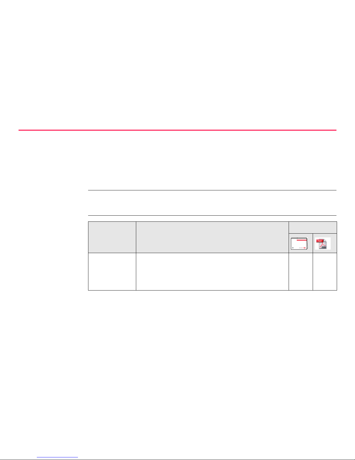
Available
documentation
Name Description Format
User Manual All instructions required in order to operate the
product to a basic level are contained in the User
Manual. Provides an overview of the product
together with technical data and safety directions.
xx
Introduction GPS1200 5
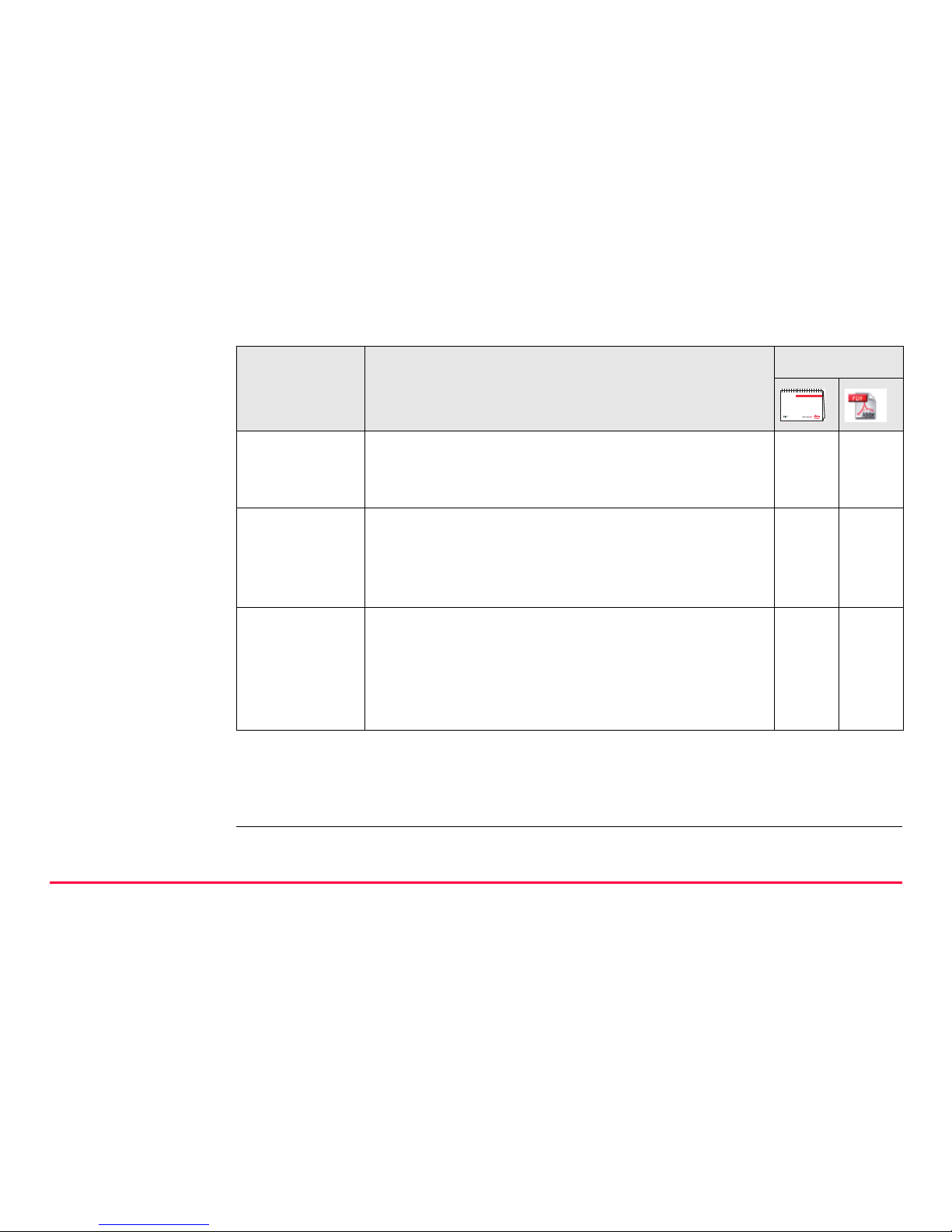
Refer to the following resources for all GPS1200 documentation and software:
• the SmartWorx DVD
• http://www.leica-geosystems.com/downloads
Name Description Format
System Field
Manual
Describes the general working of the product in
standard use. Intended as a quick reference field
guide.
-x
Applications
Field Manual
Describes specific onboard application programs
in standard use. Intended as a quick reference
field guide. The RoadRunner application program
is described in a separate manual.
xx
Technical
Reference
Manual
Overall comprehensive guide to the product and
program functions. Included are detailed descriptions of special software/hardware settings and
software/hardware functions intended for technical specialists.
-x

6GPS1200
Table of Contents
Table of Contents
In this manual Chapter Page
1 Description of the System 10
1.1 System Components 10
1.2 System Concept 15
1.2.1 Software Concept 15
1.2.2 Data Storage and Data Conversion Concept 17
1.2.3 Power Concept 19
1.3 Container Contents 21
1.4 Receiver Components 23
2 User Interface 24
2.1 Operating Principles 24
2.2 Icons 30

Table of Contents GPS1200 7
3 Operation 34
3.1 Equipment Setup 34
3.2 Battery 36
3.3 Working with the CompactFlash Card 39
3.4 Working with the Clip-On-Housings for Devices 43
3.5 Accessing Survey Application Program 53
3.6 Guidelines for Correct Results 56
3.7 Operation with a Typical Configuration Set 57
4 Reference Station 62
4.1 Overview 62
4.2 Equipment Setup 66
4.3 Getting Started with the GRX1200 Series 71
5 Care and Transport 80
5.1 Transport 80
5.2 Storage 81
5.3 Cleaning and Drying 82

8GPS1200
Table of Contents
6 Safety Directions 84
6.1 General Introduction 84
6.2 Intended Use 85
6.3 Limits of Use 87
6.4 Responsibilities 88
6.5 Hazards of Use 89
6.6 Electromagnetic Compatibility EMC 99
6.7 FCC Statement, Applicable in U.S. 102
7 Technical Data 108
7.1 Receiver Technical Data 108
7.1.1 Tracking Characteristics of the Receiver 108
7.1.2 Accuracy 113
7.1.3 Technical Data 115
7.2 Antennas Technical Data 121
7.3 RX1200 Technical Data 126
7.4 Conformity to National Regulations 130
7.4.1 RX1250 130
7.4.2 Receiver 132
7.4.3 GFU24, Siemens MC75 134
7.4.4 GFU19 (US), GFU25 (CAN), GFU26 (US) CDMA
MultiTech MTMMC-C 136

Table of Contents GPS1200 9
8 International Limited Warranty, Software License Agreement 138
Index 140

10GPS1200
Description of the System
1 Description of the System
1.1 System Components
Main components
Component Description
Receiver To calculate a range to all visible satellites.
RX1200 To operate the user interface either by the keyboard or by
the touch screen with supplied stylus.
Antenna To receive the satellite signals from the GNSS (Global
Navigation Satellite System) satellites.
LEICA Geo Office The office software including a series of help programs
which support working with GPS1200.
LEICA GNSS Spider The reference station software required to operate the
reference station receivers of GPS1200.

Description of the System GPS1200 11
Receivers
Receiver Description
GX1230 GG 14 L1, 14 L2 channels (GPS), twelve L1, twelve L2 channels
(GLONASS), two channels SBAS, code and phase, real-time
capable
GX1230 14 L1, 14 L2 channels, two channels SBAS, code and phase,
real-time capable
GX1220 GG 14 L1, 14 L2 channels (GPS), twelve L1, twelve L2 channels
(GLONASS), two channels SBAS, code and phase
GX1220 14 L1, 14 L2 channels, two channels SBAS, code and phase
GX1210 14 L1 channels, two channels SBAS, code and phase
GX1200 with
PPS/Event option
14 L1, 14 L2 channels, code and phase, real-time capable,
with event and PPS ports
GRX1200 Pro 14 L1, 14 L2 channels, code and phase, real-time capable,
with event, PPS, oscillator and NET port, for reference station
applications
GRX1200 GG Pro 14 L1, 14 L2 channels (GPS), twelve L1, twelve L2 channels
(GLONASS), code and phase, real-time capable, with event,
PPS, oscillator and NET port, for reference station applications

12GPS1200
Description of the System
)
The GX1230 GG, GX1230, GX1220 GG, GX1220, GX1200 with PPS/Event option
and GRX1200 Series receivers use the GPS P-code signal, which by U.S. policy is
liable to be switched off without notice. Phase measurements on L2 are ensured as
these receivers automatically switch to patented tracking techniques.
Antennas used
with receivers
Receiver Antenna
GX1230 GG/GX1230/
GX1220 GG/GX1220
Typically: AX1202 GG, otherwise: AT504 GG/AT504
GX1210 AX1201
GRX1200 Series Typically: AT504 GG/AT504, otherwise: AX1202 GG

Description of the System GPS1200 13
LEICA Geo Office • LGO supports the GPS1200 and TPS1200+ instruments. It also supports all
other Leica TPS instruments.
• LGO is based on a graphical user interface with standard Windows® operating
procedures.
• LGO provides the following functionality:
• Supported operating systems: Windows® XP, Windows® 2000.
Refer to the online help of LGO for additional information.
Functionality Description
Standard Functionality
Includes data exchange between computer and receiver, data
management including viewing and editing, reporting, creation
and management of codelists, creation and use of format files for
data conversion, uploading and deleting of system software and
application programs.
Extended Functionality
Includes coordinate transformations, GPS and GLONASS post
processing, level data processing, network adjustment, GIS and
CAD Export.

14GPS1200
Description of the System
LEICA GNSS
Spider
The reference station software is known as LEICA GNSS Spider. It is required to
operate the GRX1200 Series receivers.
Use
Operating systems
Refer to the online help of LEICA GNSS Spider for additional information.
• to connect from a PC to a GPS1200
receiver locally or remotely.
• to automatically convert data to
RINEX format.
• to configure receiver operation. • to automatically archive data files.
• to monitor receiver operation. • to automatically distribute to FTP
locations.
• to automatically download raw data.
• Windows® XP • Windows® 2000

Description of the System GPS1200 15
1.2 System Concept
1.2.1 Software Concept
Description All receivers use the same software concept.
Software type
Software type Description
System
software
This important software covers the basic functions of the instrument. System software is also referred to as firmware.
The programs Survey and Setup are integrated into the firmware
and cannot be deleted.
The English language is integrated into the firmware and cannot
be deleted.
Language
software
Numerous languages are available for the receivers. Language
software is also referred to as system language.
The system software enables a maximum of three languages
which can be stored at any one time - the English language and
two other languages. The English language is the default
language and cannot be deleted. One language is chosen as the
active language.

16GPS1200
Description of the System
Software upload All instrument software is stored in the System RAM of the receiver. The software
can be uploaded onto the receiver using the following methods:
• Using LGO the software is transferred via the serial interface to the CompactFlash card in the receiver, which is then stored to the System RAM.
• By connecting the CompactFlash card directly to the computer either via an
internal card slot housing or an external OMNI drive, the software is transferred to the card, which is then stored to the System RAM.
Application
programs
A suite of optional survey-specific application programs are
available for the instrument.
Some of the programs are activated freely and require no license
key and others require purchasing and are only activated with a
license key.
Customised
application
programs
Custom software specific to user requirements can be developed
using the GeoC++ development kit.
Information on the GeoC++ development environment is available on request from a Leica Geosystems representative.
RX1200
software
For RX1210 and RX1210T. This software covers display, sound
and communication settings of the RX1210 and RX1210T.
Software type Description

Description of the System GPS1200 17
1.2.2 Data Storage and Data Conve r si o n Co nc e pt
Description Data is stored within a job in a database on a memory device. This is either a
CompactFlash card or an internal memory.
Memory device
)
Unplugging connecting cables or removing the CompactFlash card during the meas-
urement may cause loss of data. Always return to GPS1200 Main Menu before
removing the CompactFlash card and switch off the instrument before removing
cables.
CompactFlash card: A CompactFlash card slot is standard. A CompactFlash
card can be inserted and removed. Various capacities are
available.
)
Whilst other CompactFlash cards may be used,
Leica recommends to only use Leica CompactFlash cards and is not responsible for data loss
or any other error that may occur whilst using a
non-Leica card.
Internal memory: An internal memory is optional. It resides inside the
receiver. Available capacity: 256 MB or 1 GB

18GPS1200
Description of the System
)
For GRX1200 Series receivers:
While in remote operation mode, stop point occupation and ring buffer logging before
removing the CompactFlash card.
Data conversion Export
Data can be exported from a job in a wide range of ASCII formats. The export format
is defined in Format Manager which is a PC tool in LEICA Geo Office. Refer to the
online help of LGO for information on creating format files.
Data can also be exported from a job in DXF or LandXML format.
Import
Data can be imported from ASCII, DXF, GSI8 or GSI16 format.
Transfer raw data
to LGO
Raw data can be transferred between the database on the CompactFlash card or
the internal memory of the receiver and LGO in two ways:
• From the CompactFlash card or the internal memory directly through a serial
interface to a project in LGO on a PC.
• From the CompactFlash card using for example an OMNI drive as supplied by
Leica Geosystems to a project in LGO on a PC.
)
CompactFlash cards can directly be used in an OMNI drive as supplied by Leica
Geosystems. Other PC card drives may require an adaptor.

Description of the System GPS1200 19
1.2.3 Power Concept
General Use the Leica Geosystems batteries, chargers and accessories or accessories
recommended by Leica Geosystems to ensure the correct functionality of the instrument.
Power options Receiver
Power for the receiver can be supplied either internally or externally. Up to two
external power supplies can be connected using a Y-cable. For the GRX1200 Series
one of the two external power supplies can be configured to be the primary which is
always used when available.
Internal power supply: Two GEB221 batteries fit into the receiver.
External power supply: GEB171 battery connected via a cable.
OR
Car battery connected via a converter cable supplied by
Leica Geosystems.
OR
10.5-28 V DC power supply via a converter cable
supplied by Leica Geosystems.
OR
110/240 V AC to 12 V DC power supply unit, supplied
by Leica Geosystems.

20GPS1200
Description of the System
)
For permanent operations use Uninterruptible Power Supply units as a back-up in
case of a main power failure.
Description of the System GPS1200 21
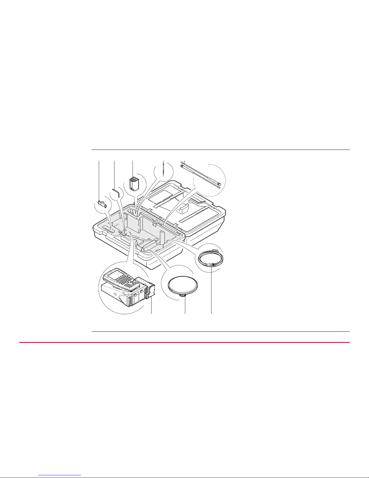
1.3 Container Contents
Container for
GX1200 receivers
and delivered
accessories
part 1 of 2
a) Double arm for antennas of
devices
b) Allen key
c) GEB221 internal battery
d) Supplied stylus
e) Antennas of device
f) GX1200 with RX1210 and
device such as radio
g) Antenna and GAD31 adapter
h) Cables
GPS12_135
a b
fgh
cde
22GPS1200
Description of the System
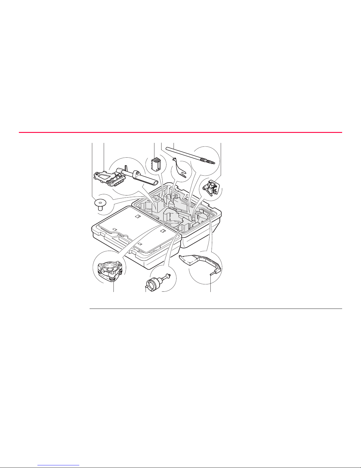
Container for
GX1200 receivers
and delivered
accessories
part 2 of 2
a) Base for telescopic rod
b) GHT39 holder for RX1210 on
pole with grip for pole
c) GEB221 internal battery
d) GAD33 arm 15 cm
e) Telescopic rod
f) Holder for GX1200 on pole
g) Tribrach
h) Carrier
i) Height hook
GPS12_136
ab cdef
gh i

Description of the System GPS1200 23
1.4 Receiver Components
Receiver components
ON/OFF button The receiver can be preprogrammed in the office and used in the field without the
RX1200 attached. In this case, the receiver is turned on by holding down the
ON/OFF button for 2 s or off by holding down the ON/OFF button for 4 s. A green
steady light at the power LED indicates that the receiver is turned on.
a) RX1200
b) Supplied stylus
c) Clip-on-contacts for connecting
RX1200 without cable
d) Recess for RX1200
e) Guide rail for clip-on-housing of a
device
f) ON/OFF button
g) LED indicators
h) Battery compartment 2 or port NET
i) Battery compartment 1
j) CompactFlash card compartment
GPS12_134
a
g
h
i
j
b
c
d
e
f

24GPS1200
User Interface
2 User Interface
2.1 Operating Principles
Keyboard and
touch screen
The user interface is operated either by the keyboard or by the touch screen with
supplied stylus. The workflow is the same for keyboard and touch screen. The difference is the way information is selected and entered.
Turn instrument on Press PROG.
Turn instrument off The instrument can only be turned off in the GPS1200 Main Menu screen.
Press both USER and PROG simultaneously.
OR
Hold ESC for 2 s.
Lock/Unlock
keyboard
Option Description
Lock To lock the keyboard press and hold SHIFT for 3 s. The message
’Keyboard locked’ is momentariliy displayed on the Message Line.

User Interface GPS1200 25
Switching between
Leica SmartWorx
software and
Windows CE
desktop
This is valid for RX1250.
Unlock To unlock the keyboard press and hold SHIFT for 3 s. The message
’Keyboard unlocked’ is momentariliy displayed on the Message Line.
Option Description
a) Icon to start Leica
SmartWorx software
b) Windows CE desktop
c) Task bar
d) Start button
RX12_33
a
b
d c

26GPS1200
User Interface
Access Leica SmartWorx software
Access Windows CE desktop
IF THEN
RX1250 is started the Leica SmartWorx software comes up automatically.
Windows CE
desktop is active
double click to display the Leica SmartWorx software.
OR
SHIFT PROG ( ) to display the Leica SmartWorx software.
Leica SmartWorx
software is minimised
double click to maximise it.
OR
select SmartWorx in the task bar to maximise it.
IF THEN
Leica SmartWorx software
is to be minimised
SHIFT MINIM (F5) in Main Menu.
Leica SmartWorx software
is to be closed
SHIFT EXIT (F6) in Main Menu.
Windows CE task bar is to
be displayed
SHIFT PROG ().
User Interface GPS1200 27
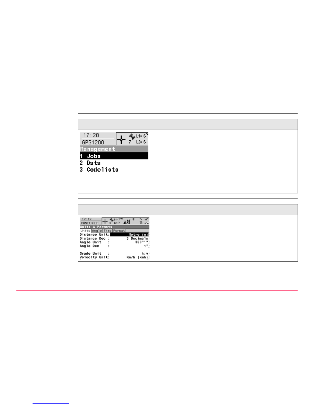
Selecting from a
menu
.
Selecting a page
Appearance Description
To select an item from a menu, do one of the following:
Move the focus to the item. ENTER or CONT (F1)
OR
Type the complete selection number in front of the
item. ENTER or CONT (F1) are not required.
OR
Tap on the item.
Appearance Description
To select a page in a screen, do one of the following:
PAGE (F6).
OR
Tap on the page tab.
28GPS1200
User Interface
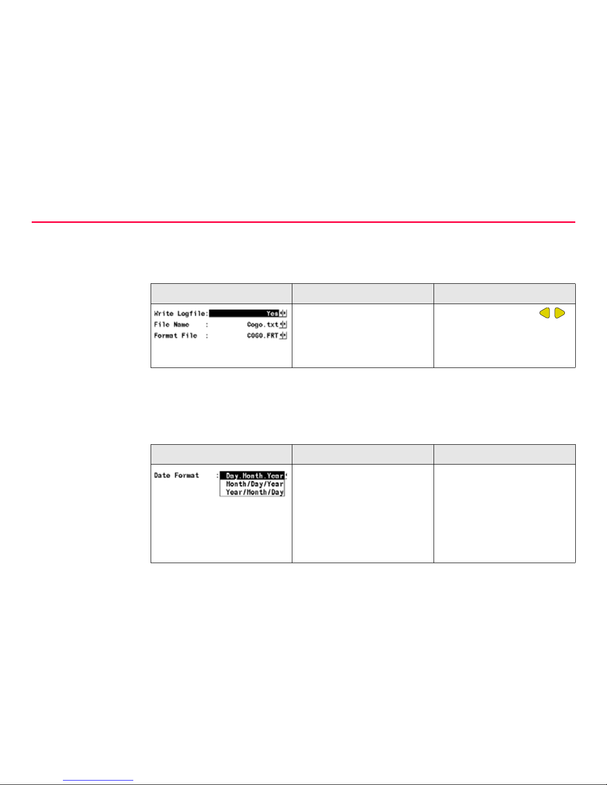
Appearance and
selection from a
choicelist
Choicelists have various appearances.
Closed choicelist
.
ENTER or tap on the field to access the choicelist. Opening a choicelist reveals
either a simple listbox or a comprehensive listbox dialogue.
Simple listbox
.
Appearance Description Selection
Triangles on the right indicate further available
choices.
Use the arrow keys
to toggle through the list or
tap the triangles on the
screen.
Appearance Description Selection
• Choicelist shows
items to select.
• A search field is
shown if necessary
• A scroll bar is shown if
necessary.
• Highlight an item and
ENTER.
• To exit without
changes ESC or tap
outside the simple
listbox.
User Interface GPS1200 29
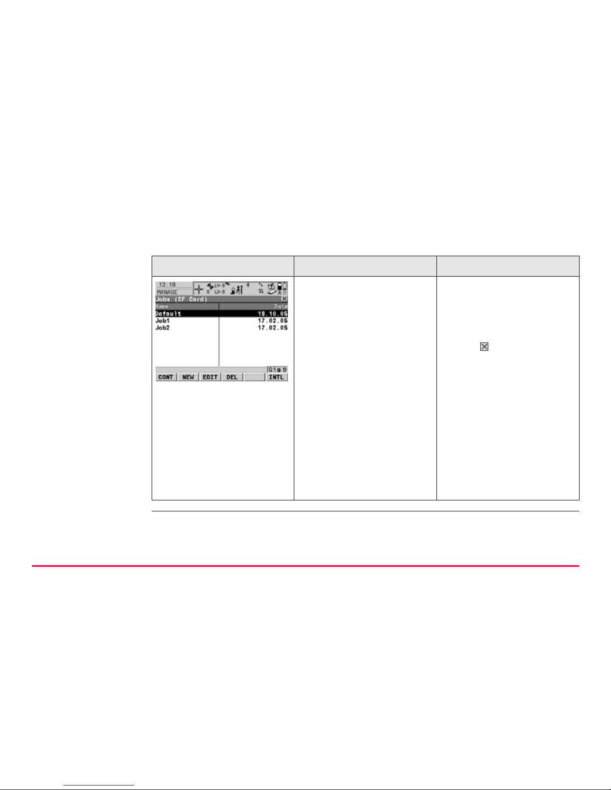
Listbox dialogue
.
Appearance Description Selection
• Choicelist fills the
whole screen.
• A search field is
shown.
• A scroll bar is shown if
necessary.
• The functionality
comprises adding,
editing and deleting of
items.
• Highlight an item and
CONT (F1) or ENTER.
• To exit without
changes press ESC or
tap .
• Listbox dialogues are
explained in detail at
appropriate places in
the manuals.
30GPS1200
User Interface
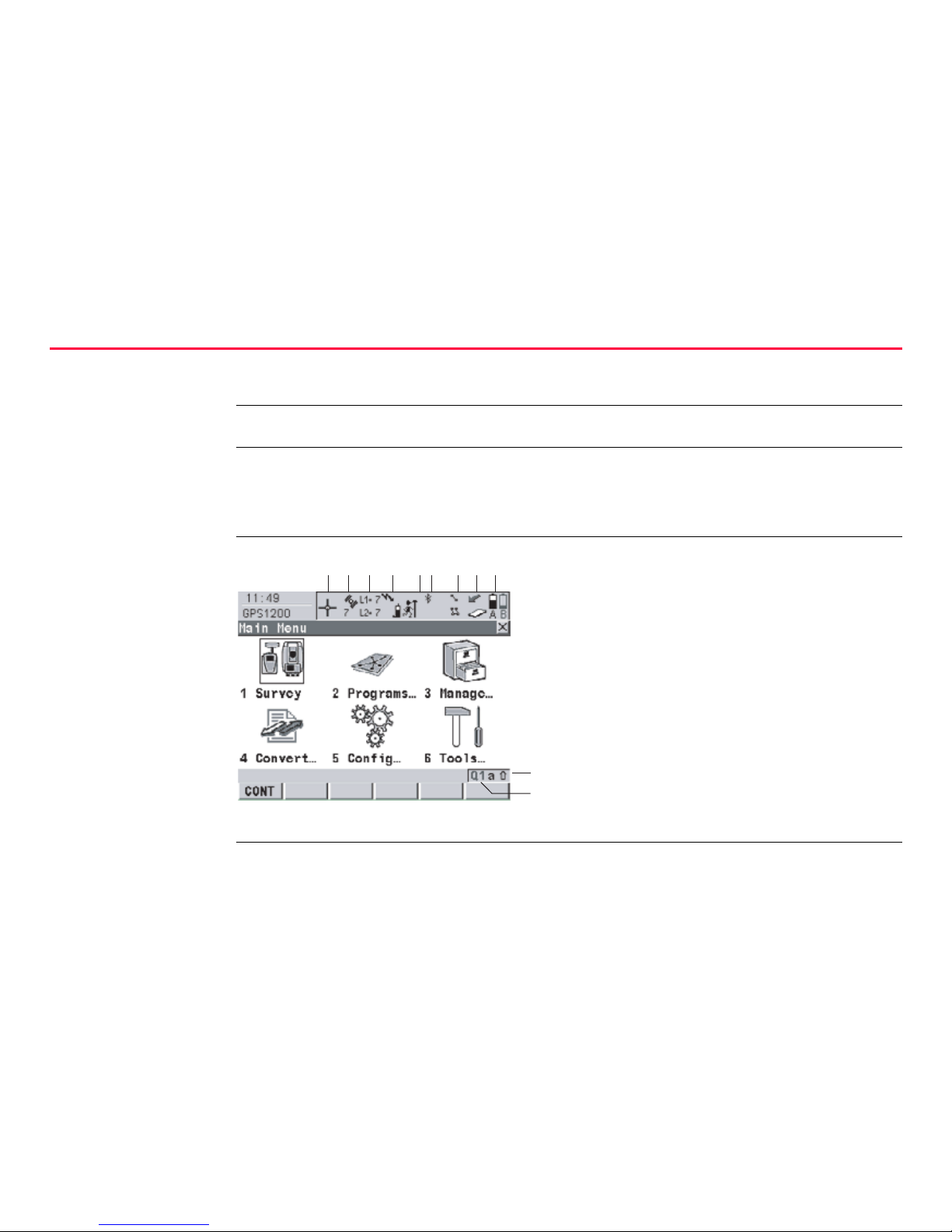
2.2 Icons
Description Icons show the current status information of the receiver.
)
The icons provide information related to basic receiver functions. The icons that
appear depend upon which GPS1200 receiver is used and the current receiver
configuration.
Position of the
icons on the screen
a) Position status
b) Number of visible satellites
c) Contributing satellites
d) Real-time device and real-time
status, Internet online status
e) Position mode
f) Bluetooth
g) Line/area
h) CompactFlash card/internal memory
i) Battery
j) SHIFT
k) Quick coding
j
a
GPS12_130
bc d ef ghi
k
 Loading...