

LEGRAND Radiant Series, WTRL10 Installation Manual

installation guide
WTRL10
Smart Switch

table of contents
before you start ..................................3
what you need ...................................4
installation and setup ................ 6–19
getting to know your switch ......20-21
specifications ...................................22
2
faqs ..............................................23
regulatory information ......... 24–27
warranty .......................................28
support ........................................29

before you start
Review this guide in its entirety before beginning device installation. Consult an
electrician with any questions or if you are unsure of your abilities.
DWarning: Incorrect installation could
result in death, serious injury, and/or
damage to your home or devices.
DCaution: To reduce the risk of injury
and/or overheating and damage to other
equipment:
• For dry, indoor use only.
• Do not use to power medical equipment.
• Not suitable as a disconnecting means.
Visit the Legrand website at www.legrand.us/radiant/smart-lighting.aspx to learn more
about your smart device.
• Do not use with loads exceeding the
device load rating (see page 22).
• Connect the smart switch to a
120 VAC, 60 Hz power source ONLY.
• Always use copper wire to install the
smart switch and follow all applicable
local and national electrical codes.
• Install in a non-metallic electrical box
to protect wireless signal strength.
3

what you need
REQUIRED:
Phillips-head screwdriver
Flat blade screwdriver
YOU MAY ALSO NEED:
Non-contact voltage tester, pliers, wire cutter, wire stripper, electrical tape,
flashlight, radiant® screwless wallplate (included), wiring leads (included), and
wire nuts (included)
NOTE: Exercise caution when using power tools. Overtightening the screws can
damage the device.
4
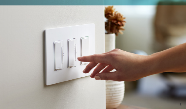
5

installation & setup
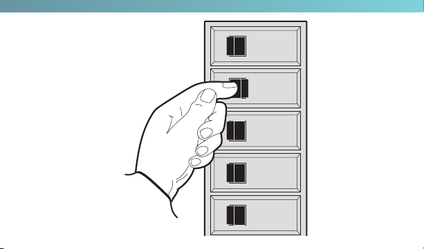
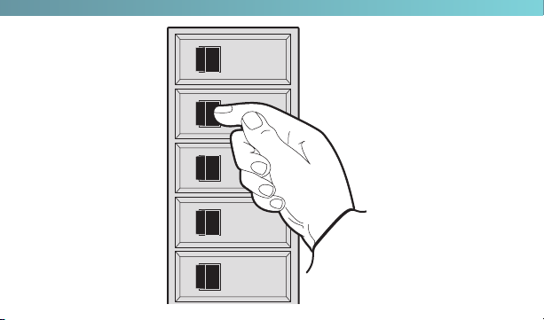
step one | turn off the power for your device at the
circuit breaker
Flip the existing light switch multiple times to confirm the power is off.
NOTES:
• If there are multiple devices next to your existing light switch, make sure power is
off at the circuit breaker for all of those devices.
• For three-way installations using a remote switch, follow the instructions for the
remote device (WTRL20).
6
ON
ON
ON
ON
ON
OFF
OFF
OFF
OFF
OFF
7

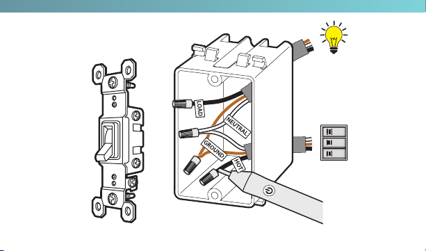
installation & setup
step two | remove the existing device
Check for the following wires:
1
HOT or LINE: Receives power from the circuit box. Referred to as “Hot” for the
purposes of this guide.
2
LOAD: Directs power to your light(s).
3
NEUTRAL: Creates a path to return current to the power source when the
device is off. Required for your switch installation.
4
GROUND: Provides a safe path for electricity in the event of a short circuit.
NOTE: Refer to “faqs” on page 23 if you are unsure of your wiring.
8
VOLTAGE
TESTER
Load
ON
OFF
ON
OFF
ON
OFF
Supply
“Hot”
9

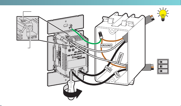
installation & setup
step three | wire the smart switch
When connecting each wire, loosen the terminal screw, insert the wire into a
terminal slot, and tighten the terminal screw until the wire is secured.
1
Connect the neutral wires to the WHITE terminal slots.
2
Connect the load wire to any LOAD terminal slot.
3
Connect the hot wire to any HOT terminal slot.
4
Connect the ground wire to the green wiring lead on the device. Use a wire nut
to secure the wires together.
NOTE: If you need extra length on your wires, wire leads are included in your packaging.
10
Terminal
slot
Terminal screw
Load
ON
ON
ON
Supply
“Hot”
NOTE: For multi-gang installations,
refer to “specifications” on page 22.
OFF
OFF
OFF
11

installation & setup
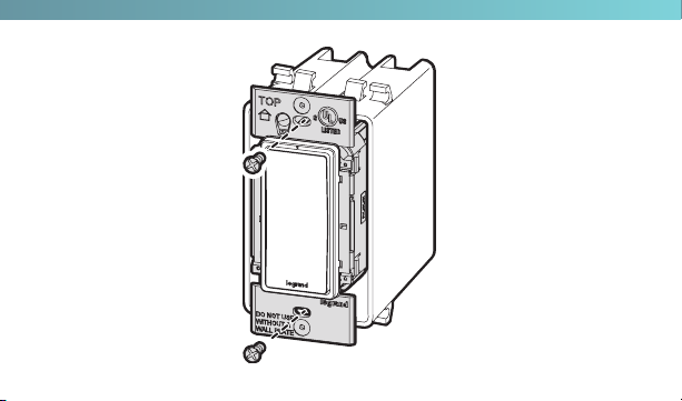
step four | secure the smart switch
1
Gently fold the wires into the electrical box. Be careful not to pinch a wire or
loosen anywire caps.
2
Use the device screws to secure the smart switch to the electrical box. Do not
fully tighten the screws.
12
13

installation & setup
step five | test the smart switch
NOTE: See page 20 for feature details.
1
Turn the power back on at the circuit breaker.
2
Press the paddle switch to turn your light on and off.
TROUBLESHOOTING TIP:
If the device is not powering, reference the “faqs” on page 23 to determine if you have
reversed the “hot” and “load” wiring.
14
ON
ON
ON
ON
ON
OFF
OFF
OFF
OFF
OFF
15

installation & setup
step six | attach the screwless wall plate
1
Noting which side faces out, align the sub-plate over the device screws. Use
the sub-plate screws (provided) to secure the sub-plate to the smart switch.
2
Tighten the device screws to secure the smart switch to the electrical box.
3
Angle the end of the screwless wall plate over the top edge of the
sub-plate. Push the screwless wall plate down and in until it “snaps” into
place over the sub-plate.
NOTE: To remove the wall plate, place the tip of a flat blade screwdriver into the slot under
the wall plate and twist gently.
16

1 32
THIS SIDE OUT
MOUNT OVER DEVICE
THIS SIDE OUT
MOUNT OVER DEVICE
THIS SIDE OUT
MOUNT OVER DEVICE
17

18

installation & setup
step seven | set up your system
1
Download and launch the Smart Lights Thread app by Legrand. The app is
available on the App Store or on Google Play.
2
Connect your smart hub (WTH1) by following the smart hub installation guide
instructions and the self-guided app instructions.
3
Connect your smart switch to the smart hub by following the instructions
within the app.
Google Play and the Google Play logo are trademarks of Google LLC. App Store is a service mark of Apple Inc., registered in the U.S. and other countries.
19
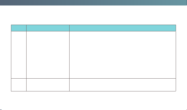
getting to know your switch
Item Name Description
• Press the top of the paddle to turn the light on
and the bottom to turn the light off.
• To return the switch to factory default, press
1 Paddle Switch
2 LED Locator Light
20
and hold the top of the paddle for 15 seconds.
The LED illuminates a solid amber color.
• To complete the factory reset, you must also
remove the device from your Samsung Artik
Cloud account before it can be recommissioned
with your existing Hub or a new Hub.
Indicates the current state of the device. Refer to
“LED Locator Light Explanations” for detail.
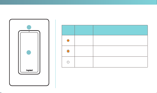
LED LOCATOR LIGHT EXPLANATIONS
2
1
LED
Color
State of
Light
Solid
Amber
Flashing
Amber
Solid
White
Explanation
Factory default; ready to
connect to your hub
Device is attempting to
connect to the network
Device is connected to your
hub and is switched off
21
specifications
Load Rating
Resistive 120 VAC, 60 Hz,15 A
Incandescent/halogen 1800 W
Ballast 15 A standard/electronic
Motor ½ HP
Legrand reserves the right to change specifications without notice.
22

faqs
Q: Which wire is the “hot” wire versus the “load” wire?
A: To determine this safely, begin by confirming that power is off to the device
location at the circuit breaker. Cap all of the exposed wires in the electrical
box, then turn the power back on to the device location. Find your noncontact voltage tester. Place your voltage tester next to each of the wires.
The voltage tester should indicate which of the two wires is receiving power
from the circuit box (refer to the voltage tester’s user manual for details on
operation). The “hot” wire is the powered wire.
To safely complete your wiring, turn off power at the circuit breaker until the
device is secured into the wall.
23

regulatory information
FCC NOTICE
This device complies with Part 15 of the FCC rules. Operation is subject to the
following two conditions: (1) this device may not cause harmful interference, and
(2) this device must accept any interference received, including interference that
may cause undesirable operation.
This equipment has been tested and found to comply with the limits for a Class
B digital device, pursuant to Part 15 of the FCC Rules. These limits are designed
to provide reasonable protection against harmful interference in a residential
installation. This equipment generates, uses, and can radiate radio frequency
energy and, if not installed and used in accordance with the instructions, may
cause harmful interference to radio communications. However, there is no
guarantee that interference will not occur in a particular installation.
24

If this equipment does cause harmful interference to radio or television
reception, which can be determined by turning the equipment off and on, the user
is encouraged to try to correct the interference by one or more of the following
measures:
• Reorient or relocate the receiving antenna
• Increase the separation between the equipment and receiver
• Connect the equipment into an outlet on a circuit different from that to which the
receiver is connected
• Consult the dealer or an experienced radio/TV technician for help
25

regulatory information
This equipment complies with FCC radiation exposure limits set forth for an
uncontrolled environment. This equipment should be installed and operated with
a minimum distance of 20 cm between the transmitter’s radiating structure(s)
and the body of the user or nearby persons.
NOTE: Any changes or modifications to this device that are not expressly approved by
the manufacturer will void the warranty and the user’s authority to operate the
equipment.
FCC ID: QOQMGM111
26

IC NOTICE
This device complies with Industry Canada license-exempt RSS standards.
Operation is subject to the following two conditions: (1) this device may not
cause interference; and (2) this device must accept any interference, including
interference that may cause undesired operation of the device.
RF EXPOSURE STATEMENT
This equipment meets the SAR evaluation limits given in RSS-102 Issue 5
requirements at the minimum separation distance of 15 mm to the human body.
Note: Any changes or modifications to this device that are not expressly approved
by the manufacturer, will void the warranty and the user’s authority to operate the
equipment.
IC ID: 5123A-MGM111
27

warranty
This product is warranted under normal use against defects in workmanship and
materials for as long as you own it. If the product fails due to a manufacturing
defect during normal use, return it for a replacement at the store where
purchased or contact technical support at 1-877-833-3303.
A dated sales receipt must be provided for all replacement requests (legible
copies are acceptable).
Additional warranty details are available at http://www.legrand.us under your
device’s product page.
28

support
IF YOU NEED HELP INSTALLING YOUR DEVICE, TALK TO OUR TECHNICAL
SUPPORT TEAM:
PHONE: 1-877-833-3303
8:00 a.m. to 8:00 p.m. EST (M-F)
EMAIL: smartlights@legrand.us
CHAT: https://www.legrand.us/radiant/smart-lighting.aspx
(Click on the icon to open a dialogue box)
29

©2018 Legra nd All Right s Reserv ed 150728 2 Rev D 08/18
Legrand, North America
301 Ful ling Mill Rd, Ste. G
Middl etown, PA 17057
1-877-833-3303
www.legrand.us
 Loading...