

Page 1
INSTALLATION INSTRUCTIONS
1. Tama o y variedad de alambre para cordones redondos nicamente. Di metro del cord n
:
Pass & Seymour/Legrand Syracuse, NY 13209
1
-
800-223-4185
Important: Turn circuit breaker OFF or remove fuse(s) and test that power is off.
WIRING INSTRUCTIONS
Install according to all codes and standards.
WARNING: IMPROPER WIRING OF ANY ELECTRICAL DEVICE CAN CAUSE SERIOUS
INJURY OR DEATH. THESE WIRING DEVICES SHOULD BE INSTALLED ONLY BY AN
ELECTRICIAN OR OTHER QUALIFIED PERSON.
NOTICE: Use this device with copper or copperclad wire only.
1. Wire Size and Range for Round Cords only. Cord Diameter:
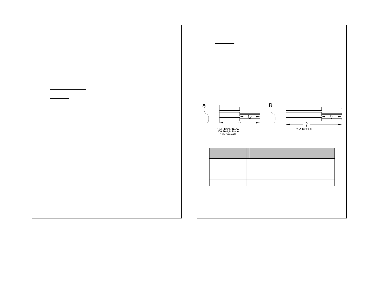
15A & 20A Straight Blade - .250" (18/3 SJ Type) to .625" (12/3 S Type).
15A Turnlok® - .250" (18/3 SJ Type) to .625" (12/3 S Type).
20A Turnlok® - .340" (18/3 SJ Type) to .650" (12/3 S Type).
2. WIRE PREPARATION: Strip wire insulation and cord jacket (Diagrams A&B). DO NOT
TIN CONDUCTORS.
3. WIRE TERMINATION: Insert cord through cover beginning from cord clamp end. Insert all
stripped conductors fully into proper wire termination holes. (Diagram C). Tighten termination
screws securely with 14 inch pounds torque.
4. ASSEMBLY: Slide cover up cord and over wire body. Tighten assemble screws, securely
attaching body to cover. Tighten cord clamp screws to 10-12 inch pounds
torque. See Warning.
INSTRUCCIONES DE INSTALACIÓN
Importante: Apague el cortacircuito o remueva el (los) fusible(s) y confirme que la
electricidad est desconectada.
INSTRUCCIONES DE CABLEADO
Instale de acuerdo con todos los c digos y normas.
ADVERTENCIA: EL CABLEADO INCORRECTO DE UN DISPOSITIVO EL CTRICO
PUEDE CAUSAR LESIONES GRAVES O A N LA MUERTE. S LO UN ELECTRICISTA U
OTRA PERSONA COMPETENTE DEBE INSTALAR ESTOS DISPOSITIVOS DE
CABLEADO.
AVISO: Utilice este dispositivo con alambres de cobre o revestidos de cobre
nicamente.
15A & 20A Straight Blade - 0.250 pulg. (tipo 18/3 SJ) a 0.625 pulg. (tipo 12/3 S).
15A Turnlok® - 0.250 pulg. (tipo 18/3 SJ) a 0.625 pulg. (tipo 12/3 S).
20A Turnlok® - 0.340 pulg. (tipo 18/3 SJ) a 0.650 pulg. (tipo 12/3 S).
2. PREPARACI N DE LOS CABLES: Retire el aislamiento de los alambres y la funda de
protecci n del cord n el ctrico (diagramas A&B). NO ESTA E LOS CONDUCTORES.
3. TERMINACIONES DE LOS CABLES: Introduzca el cord n por la tapa, a partir del extremo
de la abrazadera del cord n. Introduzca por completo todos los conductores desforrados en
los agujeros de terminaci n de cables apropiados (diagrama C). Apriete bien los tornillos de
las terminaciones aplicando 14 pulg.-lbs. de par de torsi n.
4. ENSAMBLE: Deslice la tapa hacia arriba por el cord n y sobre el cuerpo cableado. Apriete
bien los tornillos de montaje para sujetar el cuerpo a la tapa. Apriete los tornillos de la
abrazadera del cord n aplicando 10 a 12 pulg.-lbs. de par de torsi n. Consulte la Advertencia.
C
TERMINAL IDENT.
IDENTIFICACIÓN DE
TERMINAL
GROUND OR
GREEN COLOR
TIERRA O VERDE
W
BLANCO
(PLATEADO)
X or Y
X o Y
www.passandseymour.com P/N 340618 Rev. B
Aislamiento para tierra del equipo solamente.
Red, black, etc. insulation for hot conductor only
Rojo, Negro, etc aislante para Conductores Vivos Solamente
CONDUCTOR IDENT.
IDENTIFICACIÓN DE CONDUCTOR
Green insulation for equipment ground only.
White or gray insulation for neutral only.
Aislamiento Blanco o gris para
neutral solamente.
 Loading...