

Page 1
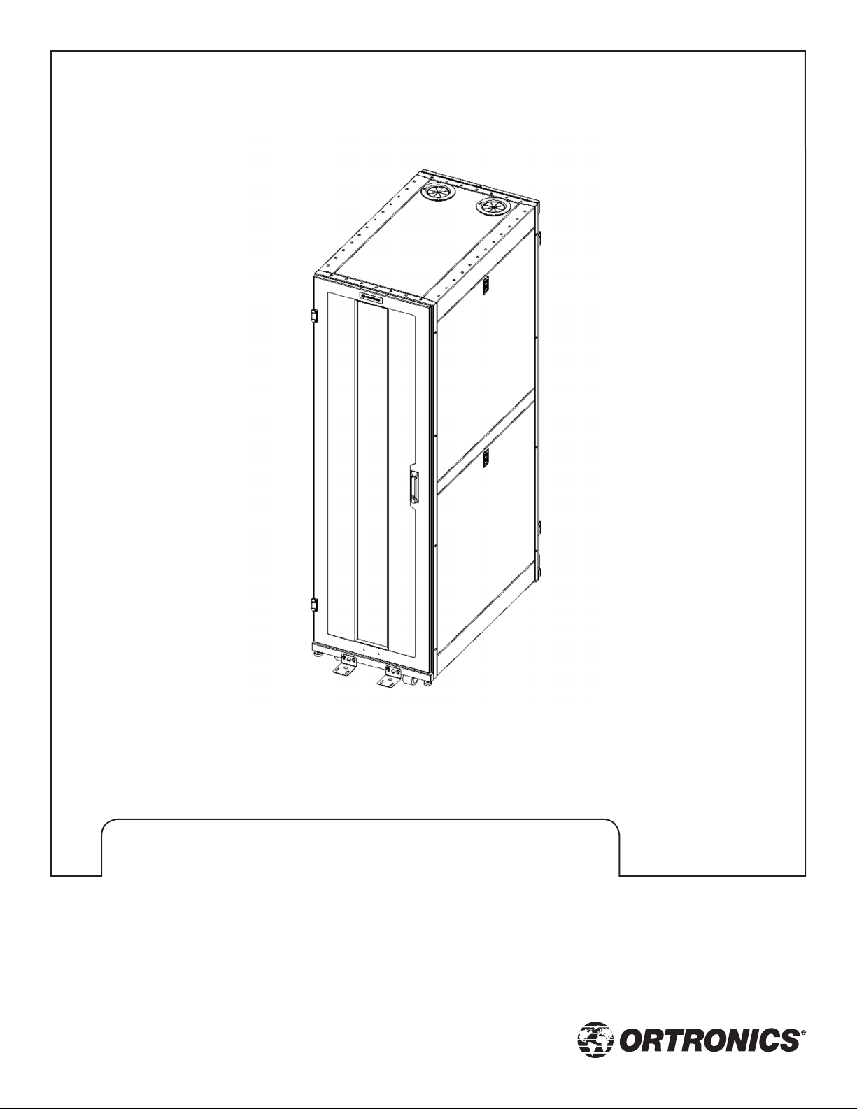
Mighty Mo® GX Series Cabinet
Installation Guide
OR-71601787 Rev. 00 - 11/11
Page 2

Safety and Warning
The exclamation point within an equilateral triangle
is intended to alert the user to the presence of
important operating and maintenance (servicing)
instructions in the literature accompanying
ATTENTION
n
Improper use of this product may lead to serious injury. Read and understand all
instructions for proper installation and use of this product.
n
Wear proper safety equipment to prevent injuries.
n
Do not attempt to unload or move the cabinets by yourself. Make sure to have sufficient
amount of personnel and equipment to safely move this product.
n
Take caution when moving the cabinets with casters. There is a possibility of tilting. Always
move cabinet over smooth floor surfaces and short distance only. Cabinet should only be
moved by pushing on the front or rear of the cabinet. Do not push from the side.
the appliance.
n
Cabinet casters are not intended to support the cabinet loads for extended periods of time.
Always use levelers to stabilize the cabinet after positioning.
n
Adjust the leveling feet to level and stabilize the cabinet before loading equipment in
the cabinet.
n
Load heavy equipment at the bottom of the cabinets first. To maintain cabinet stability, load
1/2 of the total equipment weight in the bottom 1/3 of the cabinet. Do not exceed maximum
load capacity. Load capacity information is in Product Features section.
n
Ensure that the floor has a structural load capacity that will support the weight of the
cabinet loaded with equipment.
n
Some parts of the racking system may not be effectively bonded to the Protective Earth
Terminal (PET). If these parts need to be bonded to the PET it should be done in accordance
with Article 250 of the National Electrical Code.
n
Cabinet is intended for use in ambient temperatures of 0oC to 60oC.
n
Minimum spacing between equipment and the cabinet shall be maintained in accordance
with the National Electric Code, ANSI/NFPA 70.
Rev. 00 - 11/11
Page 3

Contents
Product Features ..................................................................................................... 3
Components of GX Series ......................................................................................... 4
Hardware and Tools .................................................................................................. 5
Unpacking and Handling .......................................................................................... 6
Setting up the Cabinet
Grounding and Bonding ........................................................................................ 7
Leveling ................................................................................................................. 8
Anchoring .............................................................................................................. 9
Adjusting Vertical Mounting Rail ........................................................................ 10
Front and Rear Door: Removing and Installing .................................................. 11
Side Panel: Removing and Installing .................................................................. 12
Top panel: Removing and Installing ................................................................... 13
Ganging the Cabinets .......................................................................................... 14
Rev. 00 - 11/11
Page 4

Product Features
n
Cabinet Rack Space and Overall Heights:
– 24U (46.45”)
– 42U (77.95”)
– 45U (83.20”)
– 48U (88.45”)
n
Cabinet Widths: 24”, 29.5”, and 31.5”
n
Cabinet Depths: 36”, 42”, and 48”
n
Front Door: Full Width - Left or Right Handed or Split
n
Rear Door: Full Width - Left or Right Handed or Split
n
Side Panel: Lockable, 2 panels on each side
n
Vertical Mounting Rails:
– EIA patterned 0.375” square holes
– EIA patterned #12-24 threaded holes
n
Load ratings:
– 3,000 lbs. static weight
– 2,250 lbs. with casters
– UL Rating: 1,500 lbs. (using 4X load factor – tested to 6,000 lbs.)
n
Colors: Black and White
Rev. 00 - 11/11
3
Page 5
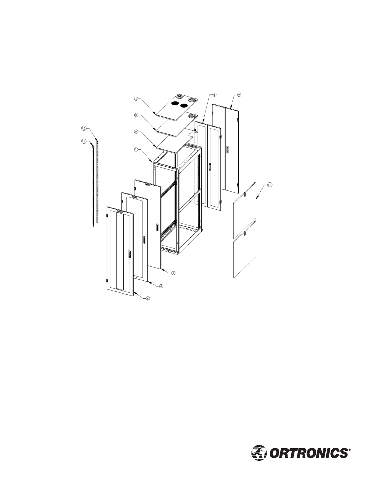
Components of GX Series
1. Frame
2. Top Panel, H Cable Entry
3. Top Panel, 2 Cable Ports
4. Top Panel, Vented with Cable Ports
5. Door, Mesh
6. Door, Plexiglass
Rev. 00 - 11/11
7. Door, Solid
8. Split Door, Mesh
9. Split Door, Solid
10. Side Panels
11. Mounting Rail, 0.375” Sq. Holes
12. Mounting Rails, #12-24 Tapped
4
Page 6

Hardware and Tools
Included Hardware
n
Door Keys (when equipped with optional doors)
n
Side Panel Keys (when equipped with optional side panels)
n
Cage Nuts and Screws (pre-configured cabinets, ordered separately on configured
to order cabinets)
n
Anchor Brackets and Bolts
Required Tools and Hardware
Unpacking
n
Utility Knife
n
3/8” Drive Socket or Open End Hand Wrench
n
Socket Wrench or Power Drill/Screwdriver
Cabinet Installation and Setup
n
Screw Driver(s) – Flat and Phillips
n
3/8” Drive Socket or Open End Hand Wrench
n
Socket Wrench or Power Drill/Screwdriver
n
1/2” Open End Hand Wrench
n
Level
n
Tape Measure
n
Step Ladder
n
Anchor Hardware – floor (NOT SUPPLIED)
n
Grounding Terminal (NOT SUPPLIED)
Rev. 00 - 11/11
5
Page 7

Unpacking and Handling
Tools Required
n
Utility Knife
n
3/8 Drive Socket
n
Socket Wrench or Power Drill/Screwdriver
Unpacking
n
Using the utility knife, carefully cut and remove the plastic wrap surrounding the cabinet.
n
Remove the four corner protectors and other honeycomb material.
n
Inspect the cabinet and inside the cabinets to insure all frame and accessory parts are
securely fastened. Remove any items that were shipped inside the cabinets that are not
installed on the frame.
n
Remove the shipping brackets anchoring the cabinet to the pallet. Do not discard the
brackets. They will be needed to the anchor the cabinets to the floor.
n
Remove the cabinet from the pallet.
¼ – 20 Hex
Head Flanged Bolts
Anchor Brackets
Rev. 00 - 11/11
6
Page 8

Setting Up the Cabinet
Screws and
Threaded Holes for
bonding conductor
Grounding and Bonding
NOTE: Proper installation of an equipment
grounding terminal must be made and the
cabinet must be grounded in accordance
with the National Electric Code, ANSI/
NFPA 70.
1. Locate two 1/4-20 threaded holes or
1/4-20 screws inside the bottom front
or rear of the cabinet. These are
marked with the ground symbol .
2. Secure the ground terminal block or
lug (not included) to the rack using
the 1/4-20 screws.
3. Attach the main earth conductor to
the terminal block or lug. Make sure
the bonding conductors are properly
crimped to the block or lug. The ground
connector size must be in accordance
with Article 250 of the National
Electric Code.
ATTENTION
Rev. 00 - 11/11
The following parts are not effectively bonded to the protective earth terminal: Rack rails,
shelves, baffle, blanking panels, cable managers. If these parts need to be bonded to the
protective earth terminal it shall be done in accordance with Article 250 of the National
Electrical Code.
7
Page 9

Setting Up the Cabinet
Flat Head Screw
Driver
Leveling
Tools: Flat Head Screw Driver or 1/2“
Open-end hand wrench (for small leveler)
1. Move the cabinet to desired location.
Use as many people as required to
safely move the cabinet.
2. Open the cabinet door(s). Locate the
holes by the bottom corners of the
cabinet. A slotted, threaded bolt will be
visible through these holes.
Holes
Leveler Foot
3. Insert a flat head screw driver into
the holes.
4. Turn the screw driver clockwise to
raise the cabinet. Turn the screw
driver counter-clockwise to lower
the cabinet. All four leveling feet
must be in firm contact with the floor.
5. Check if the cabinet is level and that
it does not ‘rock’ back and forth.
6. Check if the cabinet is at same height
as to any adjacent cabinets. Make
adjustment(s) if necessary.
NOTE: 1/2“ Open-end hand wrench can be
used to adjust the small (1 1/2“) leveler.
Rev. 00 - 11/11
8
Page 10

Setting Up the Cabinet
Without Casters:
¼ – 20 Hex
Head Flanged Bolts
Anchor Brackets
Anchoring
(Optional) Anchor the cabinets to the
floor after it has been placed in the
desired location and is level. The
hardware to anchor the cabinet to the
floor is not supplied. Use proper anchors
for the type of floor where installed.
Tools: 3/8 Drive Socket, Socket Wrench,
and Level.
1. Attach the anchor brackets to the
cabinet, in both the front and the rear,
using the supplied Hex Head Flanged
Bolts. NOTE: The brackets must be
near or touching the floor.
With Casters:
Anchor Brackets:
Long side to
the cabinet
2. Before fastening brackets to the floor,
make sure that the front and rear doors
can open and close. Make adjustments
to the brackets as necessary so that all
doors open and close.
3. Using a level check that the cabinet is
plumb. Make adjustments to levelers
as necessary.
Optional Method: Anchor brackets can
be mounted inside the cabinet. See
illustration on the left.
Rev. 00 - 11/11
Anchor Brackets
9
Page 11

Setting Up the Cabinet
Adjusting Vertical Mounting Rail
¼-20 Hex Head Bolt
(3 qty per VMA)
NOTE: Adjustment to the mounting rail
location should only be made when there
is no equipment mounted to the rails.
Tools: 3/8 Drive Socket, Socket Wrench,
Tape Measure.
1. Loosen the 1/4-20 hex head bolts
securing the VMA to the unistrut
being careful not to completely remove
the bolts. Do not remove the bolts.
There are 3 bolts per mounting rail.
2. Once all 3 bolts have been loosened,
using a tape measure, move the
mounting rails to the desired location,
and fasten the 3 bolts.
NOTE: On some cabinet models, the
mounting rails may have a spacer
bracket. Follow the instructions above
to loosen the bolts and change the VMA
location. Please ensure that the VMA is
positioned such that it mirrors the
mounting rails on the opposite side.
Rev. 00 - 11/11
10
Page 12

Setting Up the Cabinet
Hinge Pin
Front and Rear Doors:
Removing and Installing
1. All door hinges have a pin to secure the
door to the cabinet. The doors can be
detached from the cabinet by removing
the hinge pin.
2. Open the doors to disconnect the
bonding conductor located at the
bottom of the doors. The quick
disconnect can slide off the door side
so no tools are required.
3. While the door is open, lift and remove
the hinge pins from all hinges.
Bonding Conductor
4. Pull the door away from the cabinet.
NOTE: To avoid losing pins, replace pins
in hinges for future use.
5. Reverse the steps to attach the door to
the cabinet.
Rev. 00 - 11/11
11
Page 13

Setting Up the Cabinet
Push to
release latch
Side Panel: Removing and Installing
The Side Panels are equipped with a slide
latch. Keys are required to unlock the
slide latch.
1. Unlock the slide latch with the
provided keys.
Bonding Conductor
Slide Latch
2. Push lever (see illustration at left) to
release the latch.
3. Allow the side panel to tilt away from
the cabinet.
4. Disconnect the bonding conductor
located at the inside bottom corner of
the panel. The quick disconnect is
on the side panel side so no tools
are required.
5. Lift the panel and remove it from
the cabinet.
6. Reverse steps to install the side panel.
Rev. 00 - 11/11
12
Page 14
Setting Up the Cabinet
Bonding Conductor
Top Panel – Removing and Installing
Tools: Phillips Screw Driver
1. Disconnect the bonding conductor
located at the rear or front of
the cabinet.
2. Loosen or remove the 4 screws with
a phillips screw driver on both sides
of the cabinet.
3. Push up on the Top Panel and remove.
4. Reverse steps to install the to panel.
Pan Head Screws
(4 Pls)
Rev. 00 - 11/11
13
Page 15

Setting Up the Cabinet
¼-20 Flanged Hex
Screws (8 Pls)
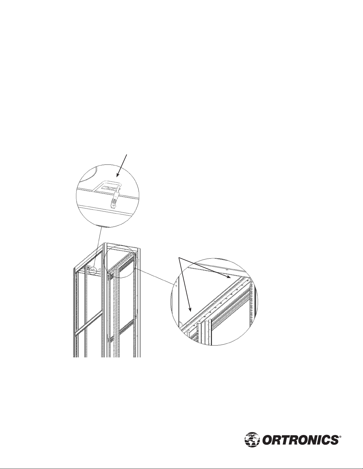
Ganging the Cabinets
Tools: 3/8 Drive Socket and Wrench
Hardware: ¼-20 Flange Hex Screws
(8 qty)
1. Position and level the adjacent cabinet.
The cabinets must be aligned both
vertically and front to back.
2. Locate 4 clearance holes in the
corner post on left side of the frame
(facing front or rear) inside the cabinet.
Insert screws into these holes and
fasten to pre-installed nuts on the
adjacent cabinet.
3. Bolt the cabinets together using
¼-20 x ¾” Long Flanged Hex screws
(8 total qty – 4 front & 4 rear).
Rev. 00 - 11/11
14
Page 16

designed to be better.
OR-71601787 Rev. 00 - 11/11
TM
125 Eugene O’Neill Drive
New London, CT 06320
800.934.5432
860.445.3800 (sales)
860.405.2974 (fax)
www.legrand.us/ortronics
 Loading...