

Page 1
OptiMo
OR-71601671
®
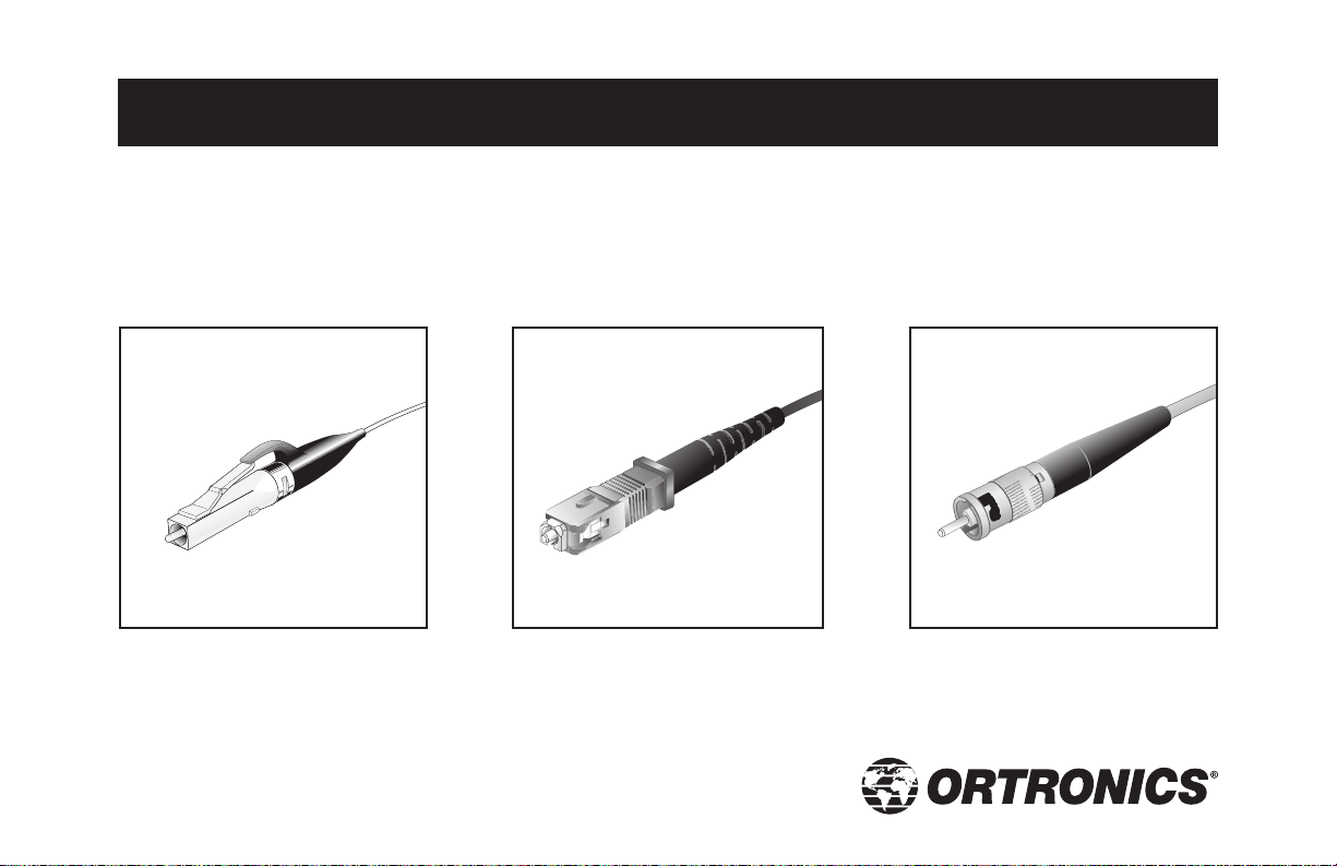
LC, SC and ST Compatible Connectors
Installation Instructions
Page 2

OptiMo®Connector
Installation Instructions
OptiMo implies the OptiMo Multimode (50 µm & 62.5 µm) and Singlemode connectors
INST REV ECN DWN BY DATE CHK BY DATE APP BY DATE
Information subject to change without notice. Ortronics reserves
the right to make changes in product design or components as
progress in engineering or manufacturing may warrant.
OptiMo Connector Installation Instructions Page i
OptiMo®is a registered trademark of Ortronics/Legrand
Page 3

Table of contents
About this guide iv
Safety precautions v
Installation on 900 µm buffered fiber or loose tube with breakout kit 1
Installation on jacketed fiber 33
Cleaning procedures 64
Fiber Preparation Guide ANNEX
OptiMo Connector Installation Instructions Page iii
Page 4

About this guide
This guide contains assembly procedures for the OptiMo®Connector.
Before starting an installation, check to make sure that you have the required tools and materials outlined at the
start of the procedure.
Review each procedure to familiarize yourself with the graphic symbols and the actions required.
OR-71601671 Page iv
Page 5

Safety precautions
CAUTION:
• When installed on a live system, invisible laser radiation may be present.
Do not stare into connector endface or view directly with optical instruments.
• Wear safety glasses when working with optical fiber.
• Dispose of all scrap fiber in the waste bottle to avoid getting fiber slivers.
OptiMo Connector Installation Instructions Page v
Page 6
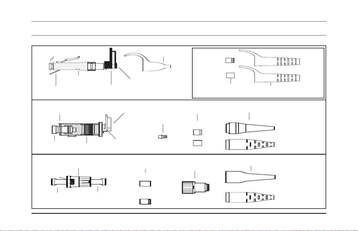
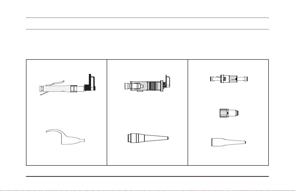
Connector components
LC
SC
ST
OR-71601671 Page vi
dust cap
connector body
Release wire
release wire
dust cap
connector body
front dust cap
disposable tool
connector body
rear dust cap
dust cap
disposable tool
900 µm strain relief boot
dust cap
Cord adapter
crimp sleeves
3.0 mm
2.4 mm
Accessories
crimp sleeves
2.4 mm
3.0 mm
rear housing
2.0 mm
3.0 mm
crimp sleeves
strain relief boots
strain relief boots
22 mmmm
33 mmmm
strain relief boots
900 µm
jacketed
900 µm
jacketed
2.0 mm
3.0 mm
Page 7

Connector installation tools
OR-71601671
OptiMo
®
LC, SC and ST Compatible Connectors
Installation Instructions
multihead adapter
table top base
OptiMo Connector Installation Instructions Page vii
universal installation tool
tool clamp
fiber cleaver
installation manual
universal stripper
scissors
ink marker
alcohol wipes
tweezers
crimping tool
microscope
fiber waste bottle
Page 8
Installation on 900 µm buffered fiber or loose tube with breakout kit
Open the bag and select the parts required for installation on 900 µm buffered fiber.
1
(Connector body and 900 µm strain relief boot.)
LC
connector body
900 µm strain relief boot
SC ST
connector body
900 µm strain relief boot
connector body with dust caps
rear housing
900 µm strain relief boot
Page 1OptiMo Connector Installation Instructions
Page 9

Installation on 900 µm buffered fiber or loose tube with breakout kit
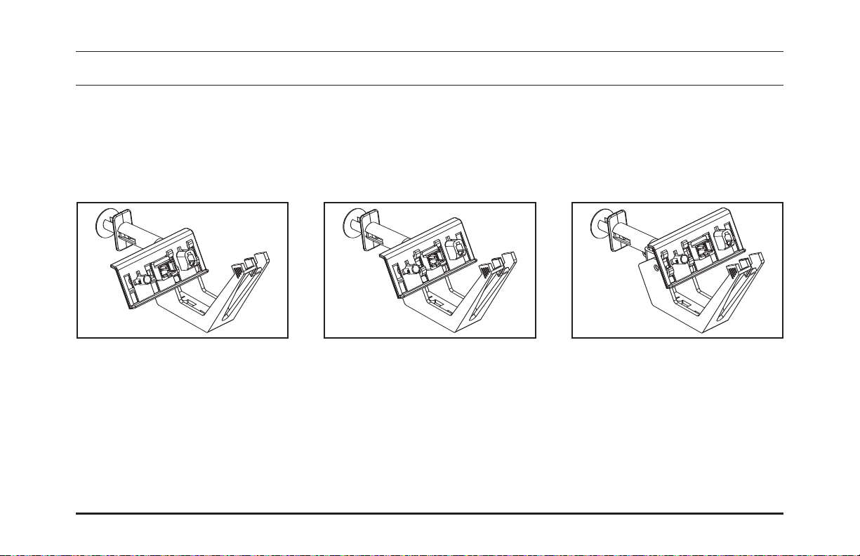
a Install the installation tool on the C clamp as shown, then clamp to the table. The table top base can be
2
used as an alternative.
OR-71601671 Page 2
Page 10
Installation on 900 µm buffered fiber or loose tube with breakout kit
b Install the multihead adapter on the tool in the appropriate position as illustrated below.
2
LC position SC position ST position
Page 3OptiMo Connector Installation Instructions
Page 11
Installation on 900 µm buffered fiber or loose tube with breakout kit
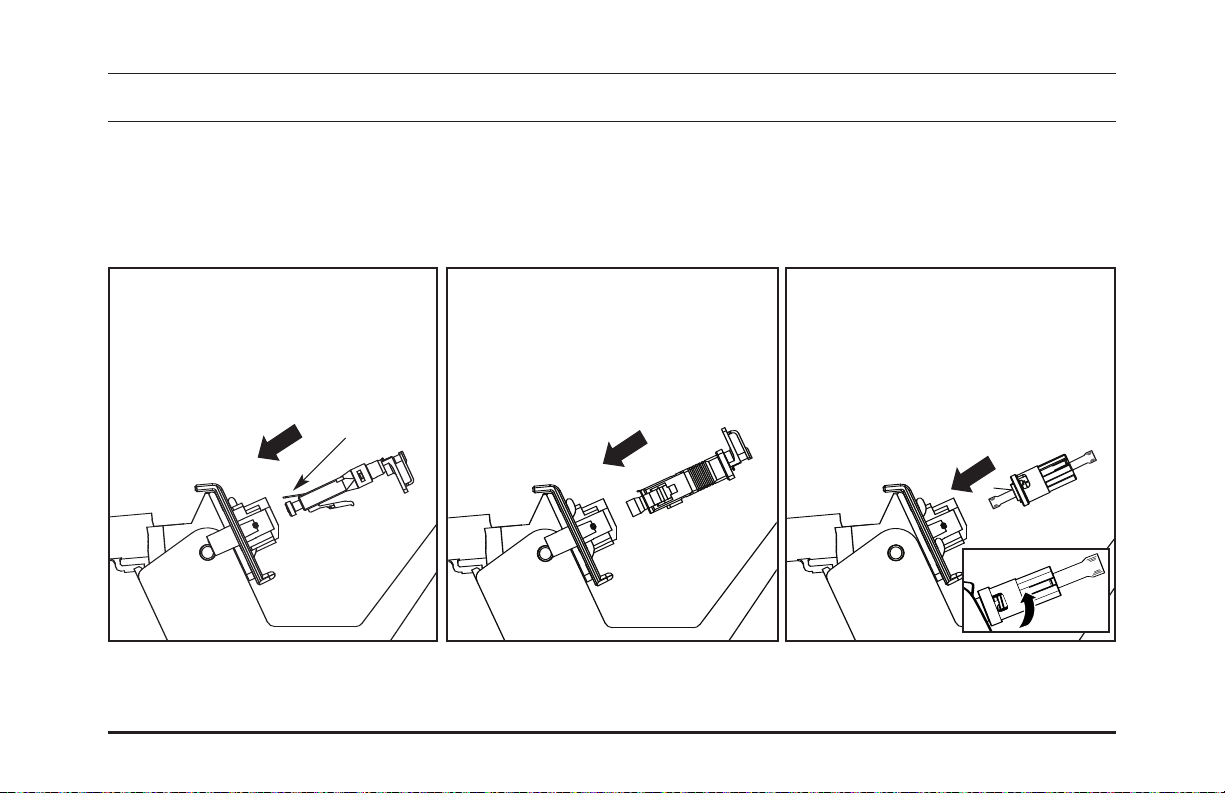
Load the connector body into the installation tool, with the release wire up.
3
LC
Leave dust cap on. Leave dust cap on.
Release wire
OR-71601671 Page 4
SC ST
By pushing the housing into the
receptacle and turning 1/4 turn
clockwise, locking it in place.
Leave dust caps on.
Page 12

Installation on 900 µm buffered fiber
4
LC
Slide the boot down the fiber, narrow
end first, until it is out of the way.
SC ST
Slide the boot down the fiber, narrow
end first, until it is out of the way.
Slide the 900 µm strain relief boot onto
the rear housing until it locks in place.
(Holding the boot on it’s smaller end will
ease insertion.) Slide the rear housing
with boot down the fiber, narrow end
first, until it is out of the way.
Page 5OptiMo Connector Installation Instructions
Page 13
Installation: stripping 900 µm tight buffered fiber (if using loose tube with breakout kit, skip to step 11)
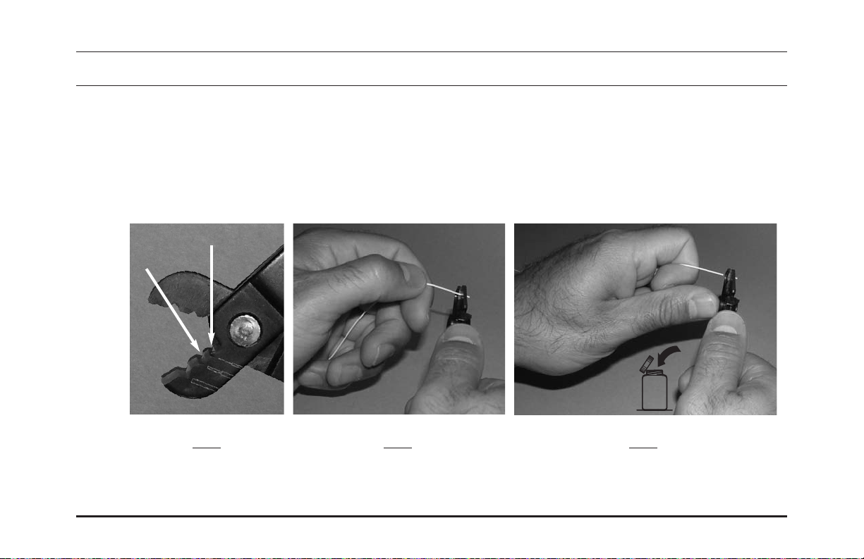
Strip approximately 40 mm of the 900 µm buffered fiber as shown below. Be sure to strip fiber in small
5
(5 mm) sections to avoid breaking it. Buffer end should be clean and square.
If unfamiliar with stripping optical fiber, it is advised to practice using a spare piece of fiber.
*
Make sure the fiber optic stripper tool you are using is in proper operating condition before attempting this step.
*
Use of a tool that is not in proper operating condition could cause the fiber to break.
900 µm "V" opening
250 µm "V" opening
Fiber waste
Fig. 1 Fig. 2 Fig. 3
Step 1. (Fig. 1) Insert fiber into Step 2. (Fig. 2) Close the tool Step 3. (Fig. 3) Draw the tool along the fiber
250 µm "V" opening of the tool. squarely around the fiber. using thumb pressure while keeping the tool
perpendicular to the fiber.
OR-71601671
Page 6
Page 14

Installation: stripping 900 µm tight buffered fiber (if using loose tube with breakout kit, skip to step 11)
Strip approximately 40 mm of the 900 µm buffered fiber. Be sure to strip fiber in small (5 mm) sections to
6
avoid breaking it. Buffer end should be clean and square. After stripping, measure and mark the buffer
from its end as illustrated below.
If unfamiliar with stripping optical fiber, it is advised to practice using a spare piece of fiber.
*
LC
15 mm
SC
11 mm
ST
9 mm
OptiMo Connector Installation Instructions
Fiber waste
Page 7
Page 15

Installation on 900 µm buffered fiber
Carefully clean the bare fiber with a folded alcohol wipe or alcohol soaked lint-free paper. Use two or
7
three passes. Avoid touching the bare fiber, or laying it down on the table, after it has been cleaned.
OR-71601671
Page 8
Page 16
Pre-Set Cleaver Installation on 900 µm tight buffered fiber (if using an adjustable cleaver, skip to step 8b)
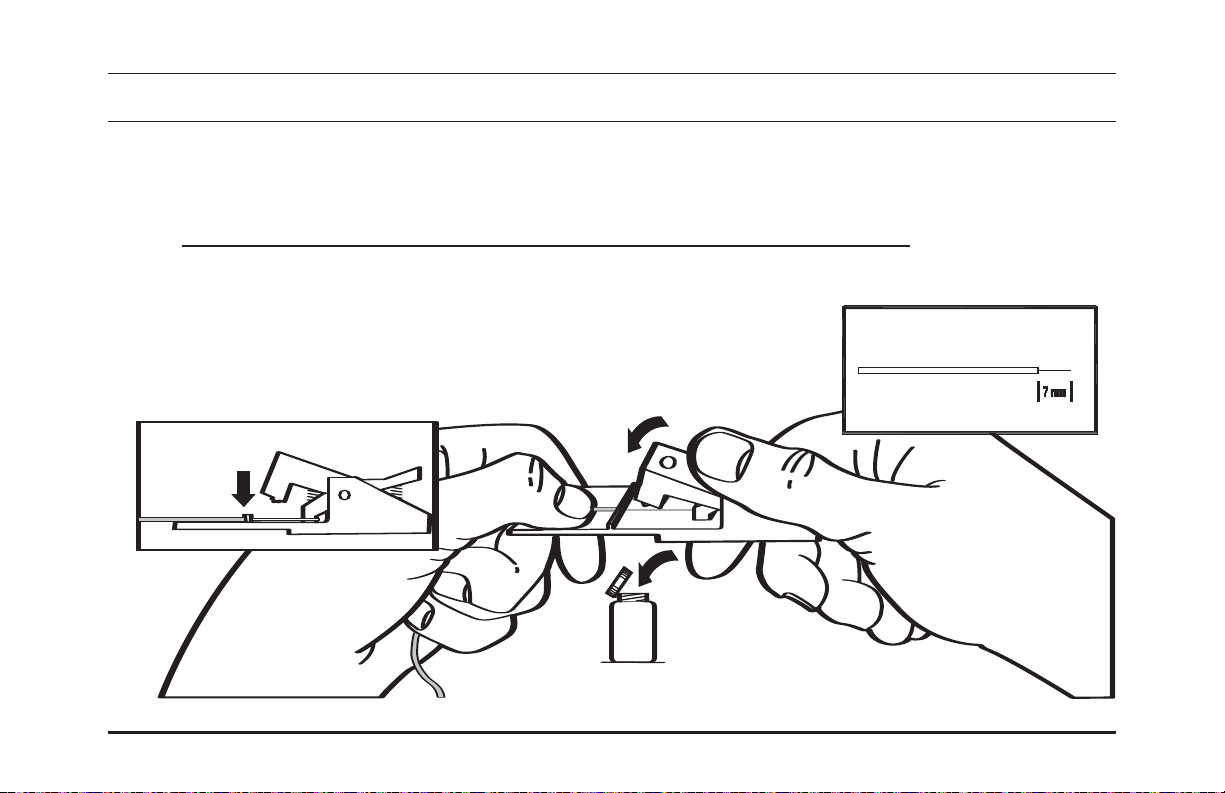
a Cleave the fiber 7 mm from the end of the buffer. Be sure to read and understand the procedure
8
included with your cleaver that is provided with your Ortronics®Field Installation Kit prior to
attempting this step. (The procedure can be downloaded from the Ortronics web site at
http://www.legrand.us/ortronics/technicalresources/instruction%20manuals.aspx)
If unfamiliar with cleaving, it is advised to practice using a spare piece of fiber. Generally, a light touch is all that is
*
required to score the fiber. The fiber buffer must rest against the stop.
Alternative cleavers which produce a 7 mm bare fiber length may be used.
+0.5
-0.0
*
Fiber waste
OptiMo Connector Installation Instructions
Page 9
Page 17

Adjustable Cleaver Installation on 900 µm tight buffered fiber
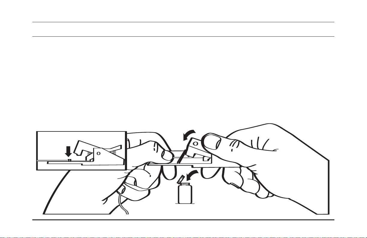
b Cleave the fiber 7 mm from the end of the buffer. Be sure to read and understand the procedure
8
included with your cleaver that is provided with your Ortronics®Field Installation Kit prior to
attempting this step. (The procedure can be downloaded from the Ortronics web site at
http://www.legrand.us/ortronics/technicalresources/instruction%20manuals.aspx)
*
*
OR-71601671
If unfamiliar with cleaving, it is advised to practice using a spare piece of fiber. Generally, a light touch is all that is
required to score the fiber. The fiber buffer must be set to produce a 7 mm bare fiber length.
Alternative cleavers which produce a 7 mm bare fiber length may be used.
+0.5
-0.0
Fiber waste
+0.5
-0.0
Page 10
Page 18
Installation on 900 µm buffered fiber
Cleave the fiber 7 mm from the end of the buffer. Be sure to read and understand the operating
9
instructions included with the cleaver. Using tweezers, discard waste fiber into the proper waste container.
If unfamiliar with cleaving, it is advised to practice using a spare piece of fiber. Generally, a light touch is all that is
*
required to score the fiber. The fiber buffer must rest against the stop.
Alternative cleavers which produce a 7 mm bare fiber length may be used.
+0.5
-0.0
*
OptiMo Connector Installation Instructions
Fiber waste
Page 11
Page 19
Installation on 900 µm buffered fiber
Use the microscope to check the quality of the cleave. Pointing the microscope at a white surface will
10
provide a brighter image.
Note: If the Ortronics®Precision Cleave Tool (OR-60300189) is used, cleave inspection with a microscope is not required.
*
Turn microscope over and place fiber on stage.
1
1
Make sure fiber position is as illustrated.
2
2
OR-71601671
Page 12
Page 20

Installation on 900 µm buffered fiber
Close stage and check fiber. It is recommended to rotate the fiber 900-180
3
3
Note: Batteries are not required.
0
to verify from different angles.
Unacceptable cleaves
Acceptable cleave
*
If the cleave is unacceptable, then the fiber must be re-prepared starting from step 5. If fiber or fiber endface
appear dirty clean it as in step 6.
Once this step is successfully completed, proceed to step 11
OptiMo Connector Installation Instructions
Page 13
Page 21
Installation: stripping 900 µm loose tube fiber with breakout kit(if using tight buffered, go to step 5)
Strip the 900 µm tube as shown below such that the distance from the end of the tube to the end of the
11
250 µm "V" opening
fiber is approximately 40 mm. Tube end should be clean and square.
If unfamiliar with cleaving, it is advised to practice using a spare piece of fiber.
*
Make sure the fiber optic stripper tool you are using is in proper operating condition before attempting this step.
*
Use of a tool that is not in proper operating condition could cause the fiber to break.
900 µm "V" opening
Fiber waste
Fig. 1 Fig. 2 Fig. 3
Step 1. (Fig. 1) Insert fiber into Step 2. (Fig. 2) Close the tool Step 3. (Fig. 3) Draw the tool along the fiber
900 µm "V" opening of the tool. squarely around the fiber. using thumb pressure while keeping the tool
perpendicular to the fiber.
OR-71601671
Page 14
Page 22

Installation: stripping 900 µm loose tube fiber with breakout kit
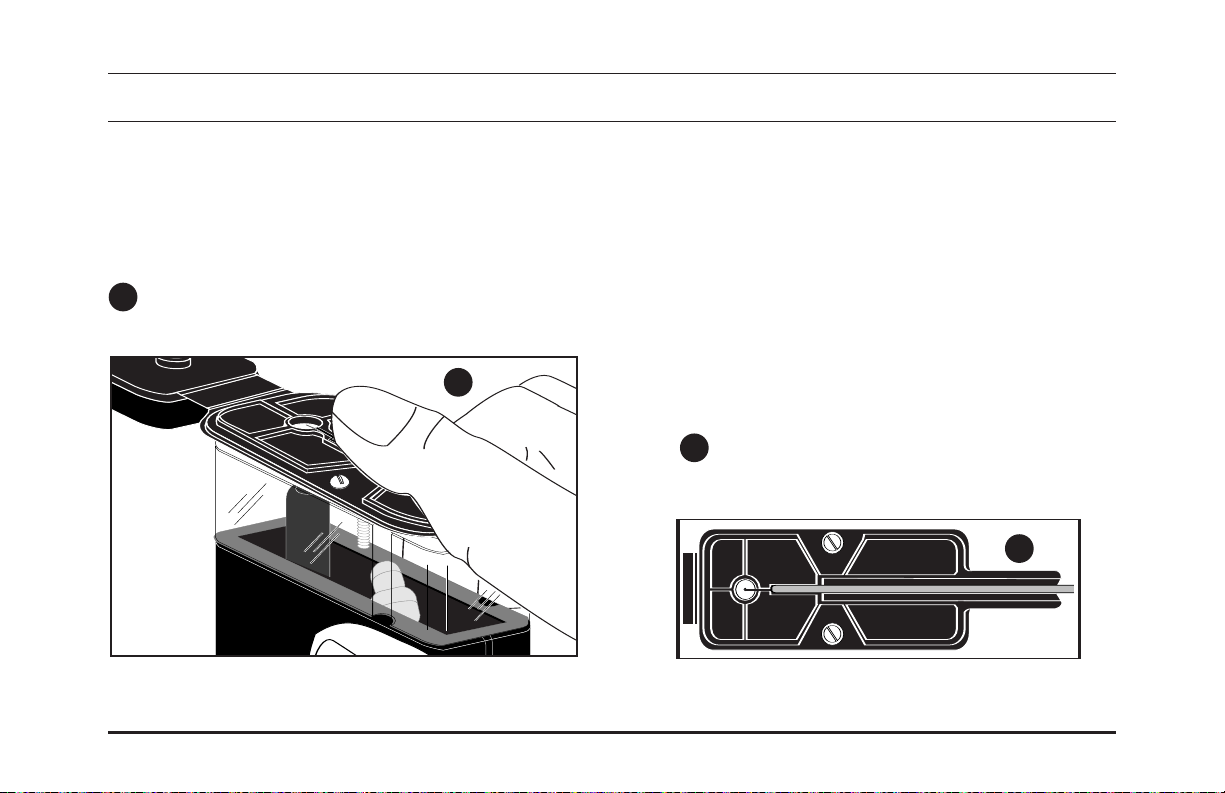
Using your fingers, carefully grip the end of the 250 µm coated fiber as shown, and gently push the fiber
12
back into the tube as far as it will go without bending.
OptiMo Connector Installation Instructions
Tube
250 µm coated fiber
Page 15
Page 23
Installation: stripping 900 µm loose tube fiber with breakout kit
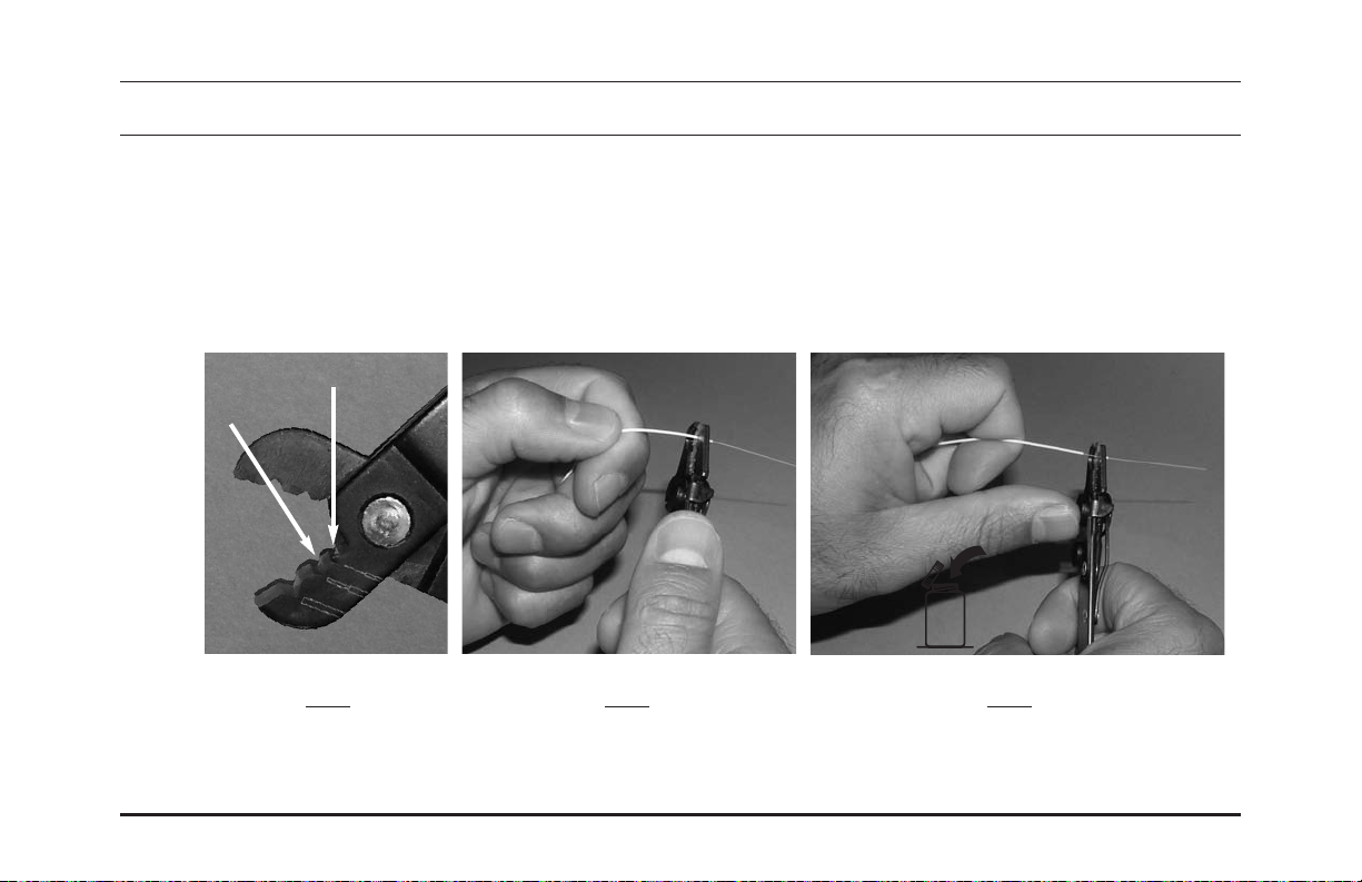
Position the fiber stripper at the end of the tube, and proceed to remove the 250 µm coating in one even
13
stripping motion as shown in Figures 1 and 2 below. 250 µm coating end should be clean and square.
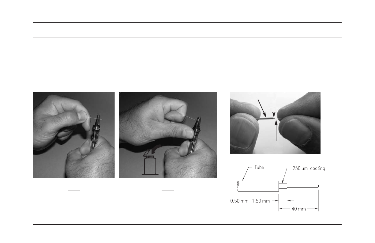
Using your fingers, carefully grip the bare fiber close to the 250 µm coating as shown in Fig. 3 below, and
gently push the fiber back into the tube as far as it will go. The 250 µm coating must always be visible
when the fiber is lightly pushed into the tube. There must be 0.50 mm–1.50 mm of 250 µm coating
extending beyond the tube as shown in Fig. 4 below.
250 µm coating
tube
fiber
Fig. 3
Fiber waste
Fig. 1 Fig. 2
Step 1. (Fig. 1) Insert fiber into the Step 2. (Fig. 2) Draw the tool along the
250 µm "V" opening of the tool fiber using thumb pressure while keeping
(shown in previous page). Close the tool perpendicular to the fiber.
the tool squarely around the fiber.
Fig. 4
OR-71601671
Page 16
Page 24

Installation: marking the 900 µm loose tube fiber with breakout kit
Place a mark 15 mm from the end of the tube, as shown below.
14
Tube
OptiMo Connector Installation Instructions
Mark
250 µm coating
15 mm
Page 17
Page 25

Installation: cleaning 900 µm loose tube fiber with breakout kit
Carefully clean the bare fiber with a folded alcohol wipe or alcohol soaked lint-free paper. Use two or
15
three passes. Use care not to remove the mark on the tube in the process. Avoid touching the bare fiber,
or laying it down on the table, after it has been cleaned.
OR-71601671
Page 18
Page 26

Pre-Set Cleaver Installation on 900 µm loose tube fiber(if using an adjustable cleaver, skip to step 16b)
a Cleave the fiber 7.0 mm–7.5 mm from the end of the 250 µm coating (not from the end of the tube).
16
Be sure to read and understand the procedure included with your cleaver that is provided with
your Ortronics®Field Installation Kit prior to attempting this step. (The procedure can be
downloaded from the Ortronics web site at
http://www.legrand.us/ortronics/technicalresources/instruction%20manuals.aspx)
If unfamiliar with cleaving, it is advised to practice using a spare piece of fiber. Generally, a light touch is all that is
*
required to score the fiber. The 250 µm coating must rest against the stop.
Alternative cleavers which produce a 7 mm bare fiber length may be used.
*
After cleaving, there must still be 0.50 mm–1.50 mm of 250 µm coating extending beyond the tube as shown. If required,
*
using your fingers, carefully grip the bare fiber close to the 250 µm coating as shown in Fig. 3 of step 13, and gently push
the fiber back into the tube as far as it will go. The 250 µm coating must always be visible when the fiber is lightly pushed
into the tube.
+0.5
-0.0
OptiMo Connector Installation Instructions
Fiber waste
Page 19
Page 27

Adjustable Cleaver Installation on 900 µm loose tube fiber
b Cleave the fiber 7.0 mm–7.5 mm from the end of the 250 µm coating (not from the end of the tube). Be
16
sure to read and understand the procedure included with your cleaver that is provided with your
Ortronics®Field Installation Kit prior to attempting this step. (The procedure can be downloaded from
the Ortronics web site at http://www.legrand.us/ortronics/technicalresources/instruction%20manuals.aspx)
*
*
*
OR-71601671
If unfamiliar with cleaving, it is advised to practice using a spare piece of fiber. Generally, a light touch is all that is
required to score the fiber. The 250 µm coating must be set to produce a 7 mm bare fiber length.
Alternative cleavers which produce a 7 mm bare fiber length may be used.
After cleaving, there must still be 0.50 mm–1.50 mm of 250 µm coating extending beyond the tube as shown. If
required, using your fingers, carefully grip the bare fiber close to the 250 µm coating as shown in Fig. 3 of step 13,
and gently push the fiber back into the tube as far as it will go. The 250 µm coating must always be visible when the
fiber is lightly pushed into the tube.
Fiber waste
+0.5
-0.0
+0.5
-0.0
Page 20
Page 28

Installation: cleave inspection of 900 µm loose tube fiber
Use the microscope to check the quality of the
17
OptiMo Connector Installation Instructions
cleave. Pointing the microscope at a white
surface will provide a brighter image. If the
cleave is unacceptable, then the fiber must be
re-prepared starting from step 11. If fiber or
fiber end-face appears dirty, reclean fiber as in
step 15.
1
Turn microscope over and place fiber on stage.
2
Make sure fiber position is as illustrated.
3
Close stage and check fiber.
4
Slowly adjust focus knob until fiber profile is clear.
5
It is recommended to rotate the fiber 90˚ - 180˚ to
verify different angles
Note: Batteries are not required.
*
If the Ortronics®Precision Cleave Tool
(OR-60300189) is used, cleave inspection
with a microscope is not required.
3
1
2
Unacceptable cleaves
Acceptable cleave
Page 21
Page 29

Installation on 900 µm tight buffered fiber or loose tube with breakout kit
Break dust cap from the disposable tool. Discard.
18
OR-71601671
Page 22
Page 30

Installation on 900 µm tight buffered fiber or loose tube with breakout kit
Carefully insert the bare fiber into the stem of the connector until you feel the end of the fiber touch the
19
fiber stub inside the connector. Gently rotating the fiber between your thumb and forefinger may ease
insertion. DO NOT rotate or remove the fiber once fully inserted into the connector. When fully inserted,
the pen mark on the buffer should be near the edge of the connector stem. Clamp the fiber into the
installation tool clamp as shown in Fig. 1. In order to ensure that the fiber end face being installed
maintains contact with the fiber end face inside the connector during subsequent handling, there MUST
BE a bow of approximately 15 mm–20 mm (0.6 in.–0.75 in.) as illustrated.
OptiMo Connector Installation Instructions
Pen mark
Installation Tool
Fiber Clamp
15 mm–20 mm
(0.6 in.–0.75 in.)
Figure 1
Page 23
Page 31

Installation on 900 µm tight buffered fiber or loose tube with breakout kit
Depress the installation tool plunger. Ensure it hooks the release wire, then slowly release the plunger.
20
Discard the release wire.
Release wire
OR-71601671
Page 24
Page 32

Installation on 900 µm buffered fiber
21
LC SC
Break dust cap from disposable tool and
discard it.
Break dust cap from disposable tool and
discard it.
ST
Remove rear dust cap from connector
body. Discard.
Page 25OptiMo Connector Installation Instructions
Page 33

Installation on 900 µm tight buffered fiber or loose tube with breakout kit
Carefully insert the bare fiber into the stem of the connector until you feel the end of the fiber touch the
22
fiber stub inside the connector. Gently rotating the fiber between your thumb and forefinger may ease
insertion. DO NOT rotate or remove the fiber once fully inserted into the connector. When fully inserted,
the pen mark on the buffer should be near the edge of the connector stem. Clamp the fiber into the
installation tool clamp as shown in Fig. 1. In order to ensure that the fiber end face being installed
maintains contact with the fiber end face inside the connector during subsequent handling, there MUST
BE a bow of approximately 15 mm–20 mm (0.6 in.–0.75 in.) as illustrated.
Pen mark
Installation Tool
Fiber Clamp
15 mm–20 mm
(0.6 in.–0.75 in.)
Figure 1
Page 26OR-71601671
Page 34

Installation on 900 µm buffered fiber
Carefully insert the bare fiber into the stem of the connector until you feel the fibers
23
make contact. Gently twisting the fiber may ease insertion. Do not twist or remove
the fiber once it is fully inserted. When fully inserted, the pen mark on the buffer
should be near the edge of the stem of the connector. Clamp the fiber into the clamp
of the installation tool. There must be a bow of approximately 15mm-20mm (0.6in-
0.75in) as illustrated in the fiber in order to maintain a contact between the end faces
of the fibers.
LC SC ST
Pen mark
clamp
OptiMo Connector Installation Instructions
Pen mark
Pen mark
Page 27
Page 35

Installation on 900 µm buffered fiber
Depress the installation tool plunger. Ensure it hooks the release wire, then slowly release the plunger.
24
LC SC
Release wire
OR-71601671
ST
Release wire Release wire
Page 28
Page 36

Installation on 900 µm buffered fiber
Unclamp the fiber. Carefully remove the connector from the installation tool. Hold the crimping tool
25
horizontally and close it partially. Load the connector into the first and smallest die (.068 hex) of the
crimping tool as shown with the disposable tool tab pointing at the crimping tool handle. The smallest
diameter hex face is against the disposable tool tab. Crimp firmly until tool release latch opens.
Make sure that the crimp tool you are using is in proper operating condition before attempting this step. Also make sure that the tool is set to the
*
settings shown in the Technical Bulletin—OptiMo®Field Installable Connectors document that is provided with your Ortronics®Field Installation Kit.
(The document can be downloaded from the Ortronics web site at http://www.legrand.us/ortronics/technicalresources/instruction%20manuals.aspx)
LC SC ST
Buffer crimp area
OptiMo Connector Installation Instructions
Buffer crimp area
Buffer crimp area
Page 29
Page 37

Installation on 900 µm buffered fiber
a
26
LC SC ST
Remove disposable tool and discard it.
Holding the boot by its collar, align the anti
snag with the latch of the LC connector,
slide it onto the rear of the connector until
its step reaches the connector body. The
installation is now completed.
Be sure to clean the connector as described
*
in the “Cleaning Procedures” section before
using the connector.
Grab the disposable tool as shown. Pull
until a click is heard. Remove the tool and
discard it.
Align and press the rear housing with boot
into the front housing until a click is heard.
The installation is now complete.
Be sure to clean the connector as described
*
in the “Cleaning Procedures” section before
using the connector.
OR-71601671
Page 30
Page 38

SC
26
Installation on 900 µm buffered fiber
b Holding the boot by its collar, slide it onto the rear of the connector until its step reaches the
connector body. The installation is now completed.
Be sure to clean the connector as described in the “Cleaning Procedures” section before using the connector
*
(See page 64).
SC only
OptiMo Connector Installation Instructions
Page 31
Page 39

Notes
OR-71601671 Page 32
Page 40

Installation on jacketed fiber
1
LC
Open the connector bag and the accessories
bag. Select the appropriate parts required for
installation on 2.0mm or 3.0mm jacketed
fiber. (Connector body, crimp sleeve and
strain relief boot)
connector body
Accessories
2.0 mm
3.0 mm
crimp sleeves
OptiMo Connector Installation Instructions
22 mm mm
33 mm mm
strain relief boots
2.0 mm
3.0 mm
SC
1a) Before you start an installation on jacketed
fiber, you need to determine the installation
method (there are two) and the parts you are
going to need. You simply have to determine the
outer diameter of the cable jacket you are
installing the connector on.
connector body
2.4 mm
3mm strain relief boots
Cord adapter
3.0 mm
crimp sleeves
ST
Open Open the bag of materials and take out the
connector body and the rear housing. In order to
select the crimp sleeve, you need to first
determine the outer diameter of the cable jacket
you are installing. The appropriate crimp sleeve
for a cord, size from 2.0 mm to 2.4 mm is the 2.4
mm sleeve. For a cord size from 2.5 mm to
3.0 mm, use the 3.0 mm crimp sleeve.
connector body
crimp sleeves
3.0 mm
2.4 mm
rear housing
3mm strain relief boots
Page 33
Page 41

Installation on jacketed fiber
a Install the installation tool on the C clamp as shown, then clamp to the table. The table top base can be
2
used as an alternative.
OR-71601671 Page 34
Page 42

Installation on jacketed fiber
b Install the multihead adapter on the tool in the appropriate position as illustrated below.
2
LC position SC position ST position
Page 35OptiMo Connector Installation Instructions
Page 43

Installation on jacketed fiber
Load the connector body into the installation tool, with the release wire up.
3
LC
Leave dust cap on.
Release wire
OR-71601671 Page 36
SC
Leave dust cap on.
ST
By pushing the housing into the
receptacle and turning 1/4 turn
clockwise, locking it in place.
Leave dust caps on.
Page 44

Installation on jacketed fiber
4
LC
Slide the boot down the fiber, narrow
end first, until it is out of the way.
SC
Slide the boot down the fiber, narrow
end first, until it is out of the way.
ST
Slide the strain relief boot onto the rear
housing until it locks in place. (Holding
the boot on its smaller end will ease
insertion.) Slide the rear housing with
boot, narrow end first.
Page 37OptiMo Connector Installation Instructions
Page 45

Installation on jacketed fiber
Using the universal stripper as shown cut squarely and remove 50 mm of the outer jacket from the end of
5
the cord. The jacket must be cut cleanly and square.
Fiber waste
OR-71601671 Page 38
Page 46

Installation on jacketed fiber
Insert the crimp sleeve down the fiber approx. 30 mm from the edge of the jacket, hold the Kevlar with
6
the crimp sleeve.
LC
SC
ST
3 mm
2 mm
3 mm
2.4 mm
3 mm
2.4 mm
Page 39OptiMo Connector Installation Instructions
Page 47

LC
7
Installation on jacketed fiber
Make sure all the slack fiber is pushed back inside the jacket. First mark the buffer at the end of the
jacket. Then mark it again at 16 mm.
LC
16 mm
OR-71601671 Page 40
Page 48

SC
Installation on jacketed fiber
a For 2.0 mm to smaller than 2.4 mm cord
8
Make sure all the slack fiber is pushed back inside the
jacket. First mark the buffer at the end of the jacket.
Mark it again at 6 mm and 17 mm.
6 mm
17 mm
b For 2.4 mm to 3.0 mm cord
8
Make sure all the slack fiber is pushed back inside the
jacket. Insert the cord adapter as shown. First mark
the buffer at the end of the cord adapter. Mark it again
at 4 mm and 15 mm.
SC
4 mm
15 mm
Page 41OptiMo Connector Installation Instructions
Page 49

ST
9
Installation on jacketed fiber
Make sure all the slack fiber is pushed back inside the jacket. First mark the buffer at the end of the
jacket. Then mark it again at 11 mm.
ST
11 mm
OR-71601671 Page 42
Page 50

Installation on jacketed fiber
Hold the fiber on the exposed buffer section. Strip the fiber to the mark. Be
10
sure to strip the buffer from the fiber in small (5 mm) sections to avoid breaking
the fiber.
LC
SC
For 2.0 mm to smaller than 2.4 mm cord
16 mm
For 2.4 mm to 3.0 mm cord
If unfamiliar with stripping optical fiber, it is advised to practice using a spare piece of fiber.
17 mm
15 mm
ST
*
11 mm
Page 43OptiMo Connector Installation Instructions
Page 51

Installation on jacketed fiber
Carefully clean the bare fiber with a folded alcohol wipe or alcohol soaked lint-free paper. Use two or
11
three passes. Avoid touching the bare fiber, or laying it down on the table, after it has been cleaned.
OR-71601671 Page 44
Page 52

Pre-Set Cleaver Installation on jacketed fiber
a Cleave the fiber 7 mm from the end of the buffer. Be sure to read and understand the procedure
12
included with your cleaver that is provided with your Ortronics®Field Installation Kit prior to
attempting this step. (The procedure can be downloaded from the Ortronics web site at
http://www.legrand.us/ortronics/technicalresources/instruction%20manuals.aspx)
If unfamiliar with cleaving, it is advised to practice using a spare piece of fiber. Generally, a light touch is all that is
*
required to score the fiber. The fiber buffer must rest against the stop.
Alternative cleavers which produce a 7 mm bare fiber length may be used.
+0.5
-0.0
*
Fiber waste
Page 45OptiMo Connector Installation Instructions
Page 53

Adjustable Cleaver Installation on jacketed fiber
b Cleave the fiber 7 mm from the end of the buffer. Be sure to read and understand the procedure
12
included with your cleaver that is provided with your Ortronics®Field Installation Kit prior to
attempting this step. (The procedure can be downloaded from the Ortronics web site at
http://www.legrand.us/ortronics/technicalresources/instruction%20manuals.aspx)
If unfamiliar with cleaving, it is advised to practice using a spare piece of fiber. Generally, a light touch is all that is
*
required to score the fiber. The fiber buffer must be set to produce a 7 mm bare fiber length.
Alternative cleavers which produce a 7 mm bare fiber length may be used.
+0.5
-0.0
*
+0.5
-0.0
Fiber waste
OR-71601671 Page 46
Page 54

Installation on jacketed fiber using preset cleaver
Press the buffer into place on the cleaver, and cleave the fiber 7 mm from the end of the buffer. Be sure
13
to read and understand the operating instructions included with the cleaver. Using tweezers, discard
waste fiber into the proper waste container.
If unfamiliar with cleaving, it is advised to practice using a spare piece of fiber. Generally, a light touch is all that is required to
*
score the fiber. The fiber buffer must rest against the stop.
Alternative cleavers which produce a 7 mm bare fiber length may be used.
*
+0.5
-0.0
Fiber waste
OptiMo Connector Installation Instructions
Page 47
Page 55

Installation on jacketed fiber
Use the microscope to check the quality of the cleave. Pointing the microscope at a white surface will
14
provide a brighter image.
Note: If the Ortronics®Precision Cleave Tool (OR-60300189) is used, cleave inspection with a microscope is not required.
*
1
Turn microscope over and place fiber on stage.
1
2
Make sure fiber position is as illustrated.
2
OR-71601671 Page 48
Page 56

Installation on jacketed fiber
Close stage and check fiber. It is recommended to rotate the fiber 900-180
3
3
Note: Batteries are not required.
*
If the cleave is unacceptable, then the fiber must be re-prepared starting from step 5. If fiber or fiber endface appear
dirty, clean it as in step 11.
0
to verify from different angles.
Unacceptable cleaves
Acceptable cleave
Page 49OptiMo Connector Installation Instructions
Page 57

Installation on jacketed fiber
15
LC SC
Break dust cap from disposable tool and
discard it.
OR-71601671 Page 50
Break dust cap from disposable tool and
discard it.
ST
Remove rear dust cap from connector
body. Discard.
Page 58

Max. 1mm
Installation on jacketed fiber
Carefully insert the bare fiber into the stem of the connector until you feel the fibers
16
make contact. Gently twisting the fiber may ease insertion. Do not twist or remove the
fiber once it is fully inserted. When fully inserted, the pen mark on the buffer should
be near the edge of the stem of the connector. Clamp the fiber into the clamp of the
installation tool. Must be a bow of approximately 15mm-20mm to maintain a contact
between the end faces of the fibers.
LC SC
ST
Max. 2 mm
Pen mark
Page 51OptiMo Connector Installation Instructions
Page 59

Installation on jacketed fiber
Depress the installation tool plunger. Ensure it hooks the release wire, then slowly release the plunger.
17
LC
Release wire Release wire
OR-71601671 Page 52
SC
ST
Release wire
Page 60

LC
18
*
Installation on jacketed fiber
Unclamp the cord. Carefully remove the connector from the installation tool. Hold the crimping tool
vertically and rest the crimping tool against the disposable tool tab to ensure it is aligned properly. The
disposable tool must be rotated in order for it’s tab to be pointing at the crimp tool handle. Using the first
and smallesr die (,068 hex) on the crimping tool, strongly crimp the stem on the buffer at the “buffer
crimp area”, making sure neither the jacket nor any aramid yarn is in the way. The smallest diameter hex
face is against the disposable tool tab.
Make sure that the crimp tool you are using is in proper operating condition before attempting this step. Also make sure that the tool is set to the
settings shown in the Technical Bulletin—OptiMo®Field Installable Connectors document that is provided with your Ortronics®Field Installation Kit.
(The document can be downloaded from the Ortronics web site at http://www.legrand.us/ortronics/technicalresources/instruction%20manuals.aspx)
Buffer crimp area
Page 53OptiMo Connector Installation Instructions
Page 61

LC
19
Installation on jacketed fiber
Remove disposable tool and discard it. Gently pull the Kevlar towards the connector to make sure there is
no slack. Slide the crimp sleeve over the Kevlar. Spread the Kevlar evenly around the connector.
Carefully remove the connector from the installation tool. Ensure the crimp sleeve is against the rear of
the connector and strongly crimp the crimp sleeve using the middle die (.128 hex) of the crimping tool.
Now you can cut excess aramid yarn.
OR-71601671 Page 54
Page 62

LC
20
*
Installation on jacketed fiber
Holding the boot by its collar, align the anti snag with the latch of the LC connector, slide it onto the rear
of the connector until its step reaches the connector body. The installation is now completed.
Be sure to clean the connector as described in the “Cleaning Procedures” section before using the connector (See page 64).
Page 55OptiMo Connector Installation Instructions
Page 63

SC
21
*
Installation on jacketed fiber
Rest the crimping tool against the disposable tool tab to ensure it is aligned properly. The disposable tool
must be rotated in order for it’s tab to be pointing at the crimp tool handle. Using the first and smallest
die (.068 hex) on the crimping tool, strongly crimp the stem on the buffer at the “buffer crimp area”,
making sure neither the jacket nor any aramid yarn is in the way. The smallest diameter hex face is
against the disposable tool tab.
Make sure that the crimp tool you are using is in proper operating condition before attempting this step. Also make sure that the tool is set to the
settings shown in the Technical Bulletin—OptiMo®Field Installable Connectors document that is provided with your Ortronics®Field Installation Kit.
(The document can be downloaded from the Ortronics web site at http://www.legrand.us/ortronics/technicalresources/instruction%20manuals.aspx)
Buffer crimp area
OR-71601671 Page 56
Page 64

SC
22
Installation on jacketed fiber
Grab the disposable tool as shown. Pull in order to expose approximately 8 mm of the sliding part and
until a click is heard. During this operation, if you are using the cord adaptor, hold it carefully and
facilitate its mating with the sliding part. Remove the tool and discard it.
Page 57OptiMo Connector Installation Instructions
Page 65

SC
23
Installation on jacketed fiber
Slide the crimp sleeve farther down the fiber to release the aramid yarn. Gently pull the aramid yarn
towards the connector to make sure there is no slack. Slide the crimp sleeve over the aramid yarn.
Spread the aramid yarn evenly around the connector. Carefully remove the connector from the
installation tool. Ensure the crimp sleeve is against the rear of the connector and strongly crimp the
crimp sleeve using the middle die (.128 hex) of the crimping tool. Now you can cut excess aramid yarn.
OR-71601671 Page 58
Page 66

SC
24
*
Installation on jacketed fiber
Holding the boot on its ribbed section, slide it onto the rear of the connector until it snaps in place. The
installation is now complete.
Be sure to clean the connector as described in the “Cleaning Procedures” section before using the connector (See page 64).
Page 59OptiMo Connector Installation Instructions
Page 67

ST
25
*
Installation on jacketed fiber
Disengage coupling nut by pushing and rotating the connector body 1/4 turn counterclockwise in order to
unlock the connector from the installation tool. Rest the crimping tool against the connector body to
ensure it is aligned properly. Using the first and smallest die (.068 hex) on the crimping tool, crimp
strongly the stem on the buffer at the “buffer crimp area”, making sure neither the jacket nor any aramid
yarn is in the way. The smallest diameter hex face is against the rear of the connector.
Make sure that the crimp tool you are using is in proper operating condition before attempting this step. Also make sure that the tool is set to the
settings shown in the Technical Bulletin—OptiMo®Field Installable Connectors document that is provided with your Ortronics®Field Installation Kit.
(The document can be downloaded from the Ortronics web site at http://www.legrand.us/ortronics/technicalresources/instruction%20manuals.aspx)
Buffer crimp area
OR-71601671 Page 60
Page 68

ST
26
Installation on jacketed fiber
Reinsert the connector in the installation tool and lock it in place. Turn the connector body housing 1/8
turn counterclockwise so the housing is resting as shown.
1
/8turn
Page 61OptiMo Connector Installation Instructions
Page 69

ST
27
Installation on jacketed fiber
Slide the crimp sleeve farther down the fiber to release the aramid yarn. Gently cut the aramid yarn
ensuring that it reaches the end of the connector body. Spread the aramid yarn evenly around the stem
of the connector. Slide the crimp sleeve down the fiber toward the connector. Ensure the crimp sleeve is
against the retaining ring at the rear of the connector body and strongly crimp the crimp sleeve using the
middle die (.128 hex) of the crimping tool.
OR-71601671 Page 62
Page 70

ST
28
*
Installation on jacketed fiber
Unclamp the cord. Align and press the rear housing with boot into the front housing until a click is heard.
Remove the connector from the installation tool. The installation is now complete.
Be sure to clean the connector as described in the “Cleaning Procedures” section before using the connector.
Page 63OptiMo Connector Installation Instructions
Page 71

Cleaning procedures
1. Wipe completely around the connector ferrule a few times with a lint-free alcohol soaked wipe. Then wipe
across the end of the ferrule.
2. Repeat step 1 with a dry wipe.
3. Blow compressed gas across the end of the ferrule (optional but recommended).
Do not allow ferrule to touch anything before inserting into coupling.
*
Preferred alcohol is ethanol but isopropyl alcohol may be used.
*
A dry cleaning tape system may also be used.
*
OR-71601671 Page 64
Page 72

Notes
OptiMo Connector Installation Instructions
Page 65
Page 73

Fiber Preparation Guide
OptiMo®LC Fiber Preparation Guide (for Multimode and Singlemode)
900 µm buffered fiber
NOT TO SCALE
*Reproductions of the above guide generated from this PDF may not be to scale.
OptiMo LC Connector Installation Instructions
Jacketed fiber
Page 74

Fiber Preparation Guide
OptiMo®SC Fiber Preparation Guide (for Multimode and Singlemode)
900 µm buffered fiber
Smaller than 2.4 mm cord
NOT TO SCALE
*Reproductions of the above guide generated from this PDF may not be to scale.
OptiMo SC Connector Installation Instructions
2.4 mm cord or larger
Page 75

Fiber Preparation Guide
OptiMo®ST-Type Fiber Preparation Guide (for Multimode and Singlemode)
900 µm buffered fiber
NOT TO SCALE
*Reproductions of the above guide generated from this PDF may not be to scale.
OptiMo ST Connector Installation Instructions
Jacketed fiber
Page 76

OptiMo
high performance
fiber optic solutions
®
http://www.legrand.us/ortronics
800-934-5432
 Loading...