

Page 1
USER´S MANUAL
BEDIENUNGSANLEITUNG
MANUEL D`UTILISATION
MANUAL DE USUARIO
INSTRUKCJA OBSŁUGI
MANUALE D‘ USO
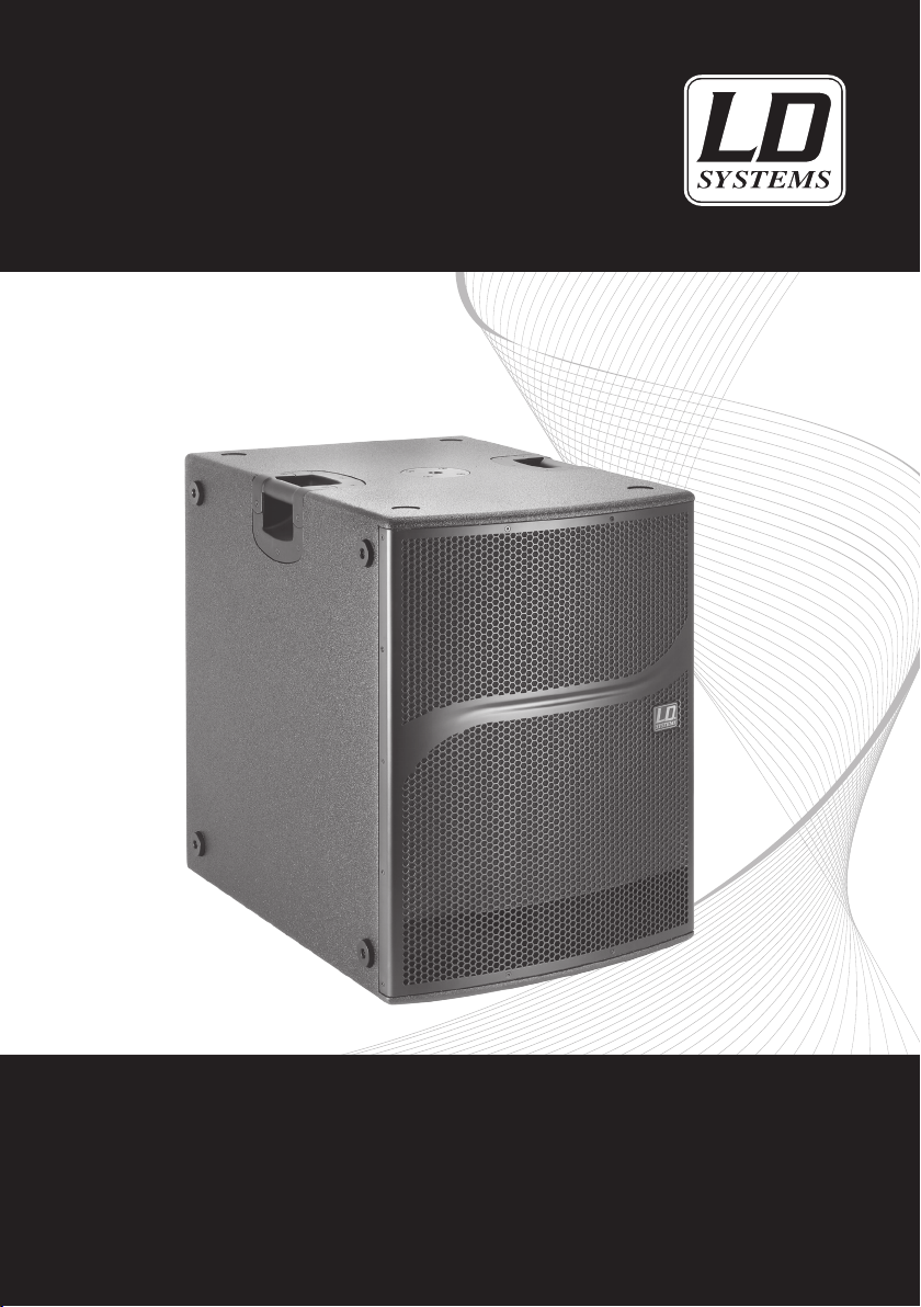
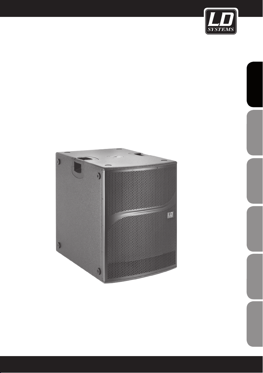
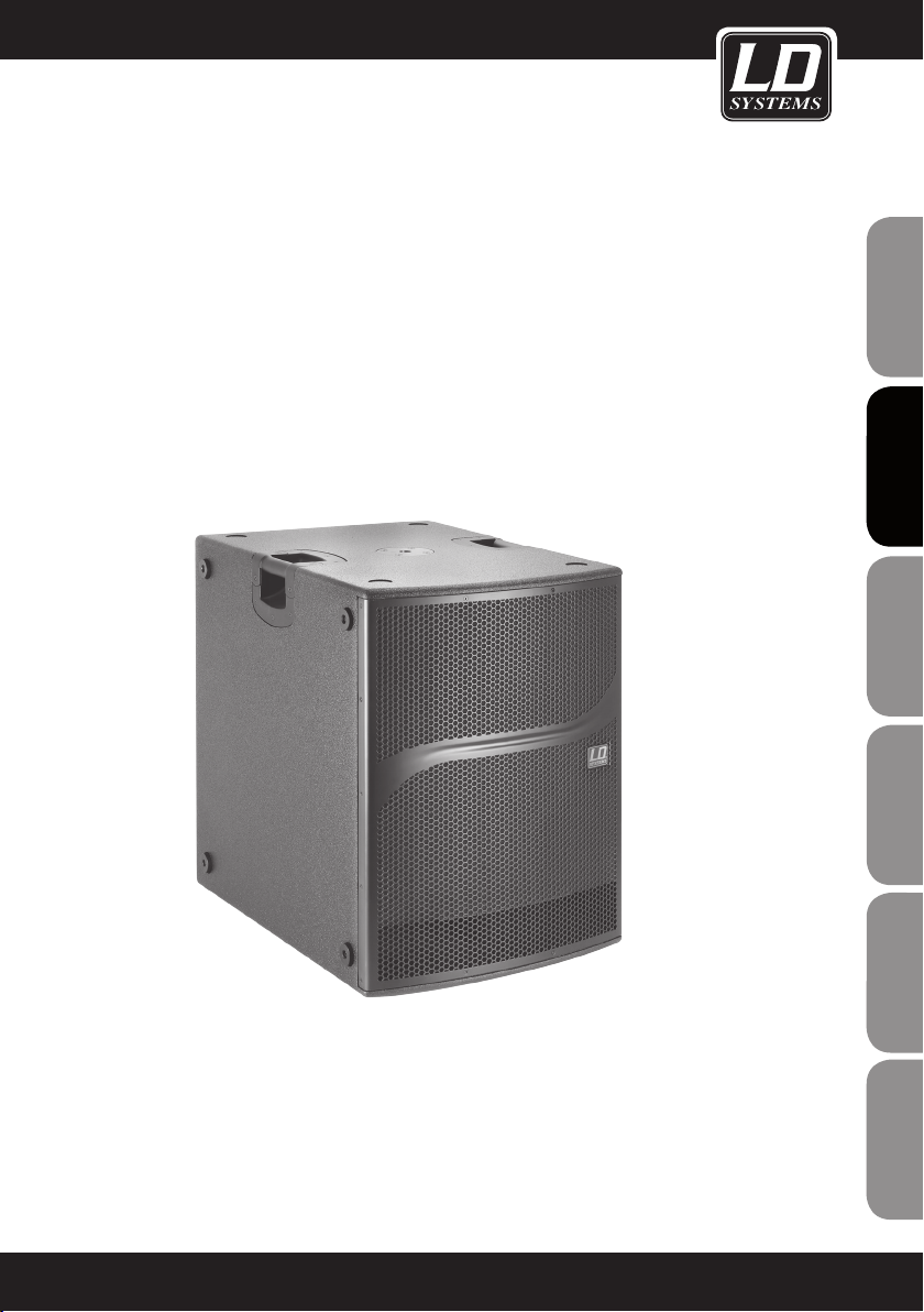
DDQ SERIES
ACTIVE SUBWOOFER WITH DSP
LDDDQSUB212 / LDDDQSUB18
Page 2
ENGLISHDEUTSCHFRANCAIS
You‘ve made the right choice!
We have designed this product to operate reliably over many years. LD Systems stands for this with its name and
many years of experience as a manufacturer of high-quality audio products.
Please read this User‘s Manual carefully, so that you can begin making optimum use of your LD Systems product
quickly.
You can find more information about LD SYSTEMS at our Internet site WWW.LD-SYSTEMS.COM
Introduction
The LD Systems DDQ subwoofers are powerful active bass speakers with digital signal processing for demanding
PA applications. They are precisely adapted for combination with the full-range speakers of the DDQ Series and are
ESPAÑOLPOLSKIITALIANO
equally suitable for use with satellites made by other manufacturers.
The compact cabinet designs are loaded with speakers with neodymium magnets driven by two 700-watt Hypex
Class D power amplifier modules with a highly efficient switching power supply and a total RMS output of 1400
(2 x 700) watt.
The Sharc DSP programmed especially for the DDQ subwoofers ensures distortion-free and reliable operation
FRANCAISFRANCAIS
FRANCAISFRANCAIS
even at maximum volume levels with a 1ms look ahead limiter, frequency and phase correction, as well as all
protection circuits, and has a large dynamic range of 127dB/113 dB (ADC/DAC). Seven DSP Presets permit
selectable crossover frequencies between 80 and 120Hz. Eight additional presets make it possible to realize
cardioid configurations of 2 or 3 subwoofers, whereby it is possible to attain rear attenuation of up to 20dB. In
addition to XLR inputs and outputs, the DDQ subwoofers have a separate mono output with a 100Hz high-pass
filter. Additional features are LED function indicators and a ground lift switch; the volume and preset controls can
be deactivated to prevent inadvertent adjustment.
The cabinets of the DDQ subwoofers are made of 18mm thick multiplex with an extremely durable polyurethane finish.
They are equipped with two M20 threaded flanges and ergonomic handles and prepared for mounting of casters.
2
Page 3
DDQ SERIES
FRANCAIS
FRANCAIS
ENGLISH
ACTIVE SUBWOOFER WITH DSP
LDDDQSUB212 / LDDDQSUB18
DEUTSCH
FRANCAIS
FRANCAIS
FRANCAIS
ESPAÑOL
POLSKI
ITALIANO
3
Page 4
PREVENTIVE MEASURES:
1. Please read these instructions carefully.
2. Keep all information and instructions in a safe place.
3. Follow the instructions.
4. Observe all safety warnings. Never remove safety warnings or other information from the equipment.
5. Use the equipment only in the intended manner and for the intended purpose.
ENGLISHDEUTSCHFRANCAIS
6. Use only sufficiently stable and compatible stands and/or mounts (for fixed installations). Make certain that wall
mounts are properly installed and secured. Make certain that the equipment is installed securely and cannot fall down.
7. During installation, observ e the applicable safety regulations for your country.
8. Never install and operate the equipment near radiators, heat registers, ovens or other sources of heat. Make
certain that the equipment is always installed so that is cooled sufficiently and cannot overheat.
9. Never place sources of ignition, e.g., burning candles, on the equipment.
10. Ventilation slits must not be blocked.
11. Do not use this equipment in the immediate vicinity of water (does not apply to special outdoor equipment in this case, observe the special instructions noted below. Do not expose this equipment to flammable materials,
fluids or gases.
12. Make certain that dripping or splashed water cannot enter the equipment. Do not place containers filled with
liquids, such as vases or drinking vessels, on the equipment.
13. Make certain that objects cannot fall into the device.
14. Use this equipment only with the accessories recommended and intended by the manufacturer.
15. Do not open or modify this equipment.
16. After connecting the equipment, check all cables in order to prevent damage or accidents, e.g., due to
tripping hazards.
17. During transport, make certain that the equipment cannot fall down and possibly cause property damage and
personal injuries.
18. If your equipment is no longer functioning properly, if fluids or objects have gotten inside the equipment or
if it has been damaged in anot her way, switch it off immediately and unplug it from the mains outlet (if it is a
powered device). This equipment may only be repaired by authorized, qualified personnel.
19. Clean the equipment using a dry cloth.
ESPAÑOLPOLSKIITALIANO
20. Comply with all applicable disposal laws in your country. During disposal of packaging, please separate
plastic and paper/cardboard.
21. Plastic bags must be kept out of reach of children.
FOR EQUIPMENT THAT CONNECTS TO THE POWER MAINS:
22. CAUTION: If the power cord of the device is equipped with an earthing contact, then it must be connected to
an outlet with a protective ground. Never deactivate the protective ground of a power cord.
FRANCAISFRANCAIS
FRANCAISFRANCAIS
23. If the equipment has been exposed to strong fluctuations in temperature (for example, after transport), do
not switch it on immediately. Moisture and condensation could damage the equipment. Do not switch on the
equipment until it has reached room temperature.
24. Before connecting the equipment to the power outlet, first verify that the mains voltage and frequency match
the values specified on the equipment. If the equipment has a voltage selection switch, connect the equipment to
the power outlet only if the equipment values and the mains power values match. If the included power cord or
power adapter does not fit in your wall outlet, contact your electrician.
25. Do not step on the power cord. Make certain that the power cable does not become kinked, especially at the
mains outlet and/or power adapter and the equipment connector.
26. When connecting the equipment, make certain that the power cord or power adapter is always freely
accessible. Always disconnect the equipment from the power supply if the equipment is not in use or if you want
4
Page 5
SAFETY:
to clean the equipment. Always unplug the power cord and power adapter from the power outlet at the plug or
adapter and not by pulling on the cord. Never touch the power cord and power adapter with wet hands.
27. Whenever possible, avoid switching the equipment on and off in quick succession because otherwise this
can shorten the useful life of the equipment.
28. IMPORTANT INFORMATION: Replace fuses only with fuses of the same type and rating. If a fuse blows repeatedly, please contact an authorised service centre.
29. To disconnect the equipment from the power mains completely, unplug the power cord or power adapter
from the power outlet.
30. If your device is equipped with a Volex power connector, the mating Volex equipment connector must be
unlocked before it can be removed. However, this also means that the equipment can slide and fall down if
the power cable is pulled, which can lead to personal injuries and/or other damage. For this reason, always be
careful when laying cables.
31. Unplug the power cord and power adapter from the power outlet if there is a risk of a lightning strike or
before extended periods of disuse.
CAUTION
RISK OF ELECTRIC SHOCK
DO NOT OPEN
CAUTION:
Never remove the cover, because otherwise there may be a risk of electric shock. There are no user serviceable
parts inside. Have repairs carried out only by qualified service personnel.
The lightning flash with arrowhead symbol within an equilateral triangle is intended to alert the user
to the presence of uninsulated “dangerous voltage” within the product’s enclosure that may be of
sufficient magnitude to constitute a risk of electrical shock.
The exclamation mark within an equilateral triangle is intended to alert the user to the presence of
important operating and maintenance instructions.
FRANCAIS
FRANCAIS
ENGLISHENGLISH
DEUTSCH
FRANCAIS
FRANCAIS
FRANCAIS
ESPAÑOL
CAUTION – HIGH VOLUME LEVELS WITH AUDIO PRODUCTS!
This equipment is intended for professional use. Therefore, commercial use of this equipment is subject to the
respectively applicable national accident prevention rules and regulations. As a manufacturer, Adam Hall is
obligated to notify you formally about the existence of potential health risks.
Hearing damage due to high volume and prolonged exposure: When in use, this product is capable of producing
high sound-pressure levels (SPL) that can lead to irreversible hearing damage in performers, employees, and
audience members. For this reason, avoid prolonged exposure to volumes in excess of 90 dB.
CAUTION! IMPORTANT INFORMATION ABOUT LIGHTING PRODUCTS
1. Do not look into the beam from a distance of less than 40 cm.
2. Do not stare into the beam for extended periods at short-to-medium distances.
3. Do not view the beam directly with optical instruments such as magnifiers.
4. Under some circumstances, stroboscopic effects may trigger epileptic seizures in sensitive individuals! For this
reason, persons who suffer from epilepsy should always avoid places where strobe lights are used.
POLSKI
ITALIANO
5
Page 6
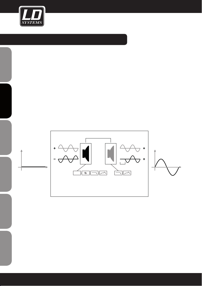
DDQSUB CARDIOID TECHNOLOGY:
The DDQSub cardioid technology makes it possible to influence the dispersion behaviour of a subwoofer setup
through the use of specific DSP programming. This makes it possible to transform a nearly omnidirectional
dispersion characteristic into a cardioid dispersion characteristic in the sub-bass frequency range This requires
ENGLISHDEUTSCHFRANCAIS
at least two subwoofers of the same type. By setting up one of the subwoofers within a cardioid setup so that
it is rotated by 180° or spatially set off, the sound energy dispersed behind the bass array can be minimised by
means of time delay and amplitude correction. This is achieved by setting up the subwoofer in one of four setups
and activating one of the preset DSP programs for each subwoofer
SCHEMATIC DIAGRAM OF A CARDIOID SUBWOOFER ARRAY WITH FUNCTIONALITY AND EFFECT
d = λ/4
Rear Front
= 2* λ/4
Δt
Time delay
Laufzeit
Phase
Crossover / GainEQCrossover / Gain
ESPAÑOLPOLSKIITALIANO
EQ
The spatially separate positioning of the subwoofers results in a time delay between the front and rear subwoofers.
FRANCAISFRANCAIS
FRANCAISFRANCAIS
This difference is adjusted within the DSP preset through time delay, amplitude, and phase correction so that maximum
addition of sound waves results in front of the subwoofer array. With the same setting, sound waves cancel out one
another at the rear of the subwoofer array, thus producing the desired rear attenuation of the overall system.
6
Page 7
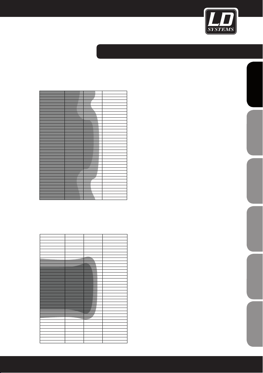
Frequency [kHz]
Rear
Frequency [kHz]
Rear
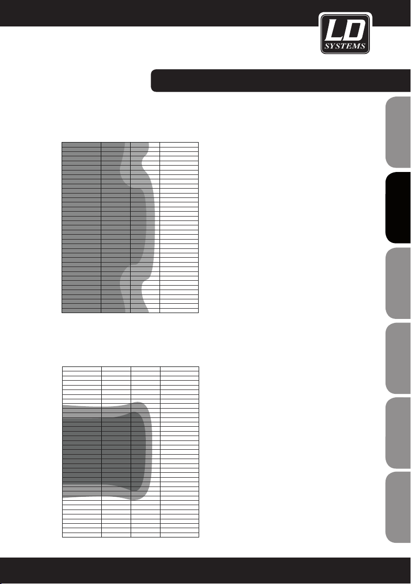
DDQSUB CARDIOID TECHNOLOGY:
FRANCAIS
FRANCAIS
DISPERSION BEHAVIOUR OF A CONVENTIONAL
SUBWOOFER SETUP (simplified depiction)
180°
USE OF THE DDQ SUBWOOFERS AS A CARDIOID
SUBWOOFER ARRAY
The DSP presets A1 - D2 are sophisticated DSP programs
that make it possible to attain a cardioid dispersion
pattern by combining two or three DDQ subwoofers.
120°
This results in the following advantages in comparison
with conventional subwoofer setups:
60°
-a rear attenuation of up to 20 dB
-enhanced bass presence in the audience area
0°
Front
-avoidance of unwanted reflections from rear walls
-reduction of diffuse sound in rooms
-60°
-elimination of bass frequency interference onstage
-differentiated sound for onstage monitoring
-reduction of the risk of feedback when using stage
-120°
microphones
Use only DDQ subwoofers of the same type for
-180°
Rear
0,1 0,2 0,50,02 0,05
cardioid setups.
The same audio signal must be present at all subwoofers
used for a cardioid setup.
The GAIN control settings must be identical on all
DISPERSION BEHAVIOUR OF A CARDIOID
SUBWOOFER ARRAY (simplified depiction)
180°
subwoofers used for a cardioid setup.
The DSP preset must be set individually for each
subwoofer.
Whether the subwoofer is operated vertically or
120°
60°
horizontally is unimportant for the functioning of the
cardioid presets.
ENGLISH
DEUTSCH
FRANCAIS
FRANCAIS
FRANCAIS
ESPAÑOL
POLSKI
Front
Rear
-120°
-180°
0°
-60°
0,1 0,2 0,50,02 0,05
ITALIANO
7
Page 8
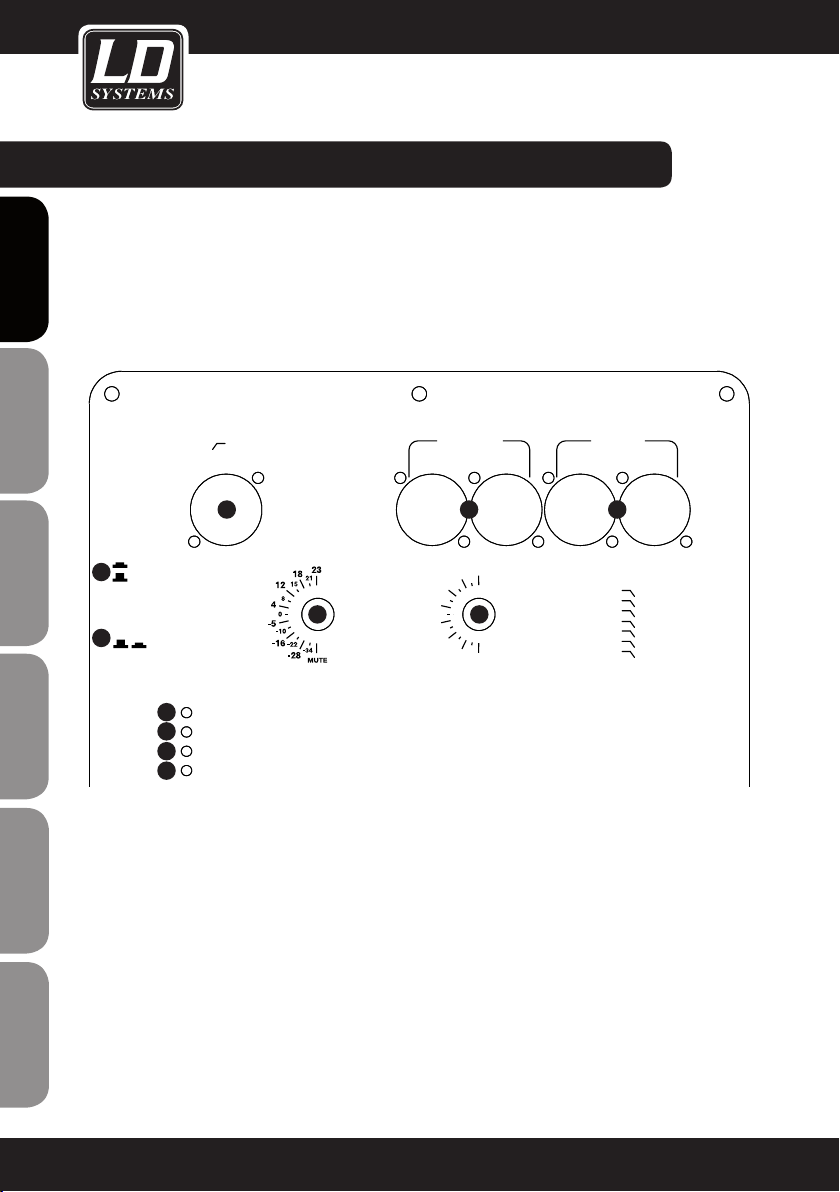
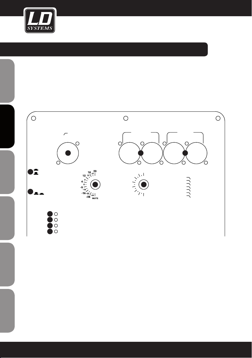
CONNECTIONS, CONTROLS, AND INDICATORS:
ENGLISHDEUTSCHFRANCAIS
6
7
ESPAÑOLPOLSKIITALIANO
FRANCAISFRANCAIS
FRANCAISFRANCAIS
DSP/GAIN
DISABLE
ENABLE
GROUND
LIFT
8
9
10
11
AUX OUTPUT
(HPF 100 Hz)
3
DSP/GAIN DISABLE
PEAK LIMIT
SIGNAL
OPERATE
ANALOG INPUT
(MAX. 23dBu)
INPUT LINK
DDQ SAT
21
RIGHT
GAIN dB
4
7
A2
B2
LEFT RIGHT LEFT
1
3
2
4
5
6
A1
B1
DSP PRESET
5
C1
D1
C2
D2
PRESETS
1 = LPF 90 Hz (DDQ)
2 = LPF 80 Hz
3 = LPF 85 Hz
4 = LPF 95 Hz
5 = LPF 100 Hz
6 = LPF 110 Hz
7 = LPF 120 Hz
8
Page 9
CONNECTIONS, CONTROLS, AND INDICATORS:
1
ANALOG INPUT LEFT / RIGHT
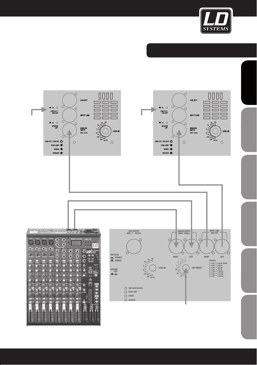
Balanced left and right XLR line inputs.
In order to use one subwoofer with two satellite speakers as a stereo sound system, connect the left and right
outputs of the sound source (e.g., mixer) with the left and right inputs of the subwoofer (ANALOG INPUT LEFT/
RIGHT). Now connect the left output of the subwoofer (INPUT LINK LEFT) to the active satellite speaker on the
left side and the right output of the subwoofer (INPUT LINK RIGHT) to the active satellite speaker on the right
side. The signal for the subwoofer is generated as a mono master signal from the stereo input signal.
In order to use two subwoofers with two satellite speakers as a stereo sound system, connect the left output
socket of the sound source to the input socket of the subwoofer on the left side (ANALOG INPUT LEFT or RIGHT).
If you have chosen the left input socket (ANALOG INPUT LEFT), now you must also use the left output socket
(INPUT LINK LEFT) to connect the satellite speaker on the left side and vice versa. Proceed analogously with
the right output socket of the sound source and the subwoofer with satellite speaker on the right side. Use only
balanced XLR cables to make the connections.
2
INPUT LINK - DDQ SAT LEFT/RIGHT
Balanced left and right XLR outputs. The signal present at the INPUT LINK output sockets is the same signal
present at the ANALOG INPUT input sockets. If LD Systems DDQ full-range speakers are used as satellite
speakers with the DDQ subwoofers, then the INPUT LINK output sockets must be used to drive them, since
the DDQ full-range speakers have a switchable high-pass filter.
3
AUX OUTPUT
Balanced XLR output with 100 Hz high-pass filter (mono master output from the left and right input signals).
For using active full-range speakers that do not have a switchable high-pass filter.
4
GAIN DB
Input sensitivity control with respect to the volume of the amplifier module. If the maximum input level (23 dBu)
is exceeded, this is indicated by collective flashing of LEDs 8-11. In this case, reduce the level of the signal
source to avoid negative effects on the sound.
FRANCAIS
FRANCAIS
ENGLISH
DEUTSCH
FRANCAIS
FRANCAIS
FRANCAIS
ESPAÑOL
5
DSP PRESET
The DSP presets 1 - 7 are DSP programs that set various low-pass filters (LPF) in the subwoofer
channel.
Preset 1: low-pass filter (LPF) 90 Hz. Use with loudspeakers in the LD Systems DDQ full-range series.
Preset 2: low-pass filter (LPF) 80 Hz.
Preset 3: low-pass filter (LPF) 85 Hz.
Preset 4: low-pass filter (LPF) 95 Hz.
Preset 5: low-pass filter (LPF) 100 Hz.
Preset 6: low-pass filter (LPF) 110 Hz.
Preset 7: low-pass filter (LPF) 120 Hz.
POLSKI
ITALIANO
9
Page 10
AUX OUTPUT
(HPF 100 Hz)
ANALOG INPUT
(MAX. 23dBu)
RIGHT
GAIN dB
DSP/GAIN DISABLE
PEAK LIMIT
SIGNAL
OPERATE
DSP PRESET
1
D2
2
4
6
A1
B1
C1
D1
3
5
7
A2
B2
C2
LEFT RIGHT LEFT
PRESETS
1 = LPF 90 Hz (DDQ)
2 = LPF 80 Hz
3 = LPF 85 Hz
4 = LPF 95 Hz
5 = LPF 100 Hz
6 = LPF 110 Hz
7 = LPF 120 Hz
INPUT LINK
DDQ SAT
AUX OUTPUT
(HPF 100 Hz)
ANALOG INPUT
(MAX. 23dBu)
RIGHT
GAIN dB
DSP/GAIN DISABLE
PEAK LIMIT
SIGNAL
OPERATE
DSP PRESET
1
D2
2
4
6
A1
B1
C1
D1
3
5
7
A2
B2
C2
LEFT RIGHT LEFT
PRESETS
1 = LPF 90 Hz (DDQ)
2 = LPF 80 Hz
3 = LPF 85 Hz
4 = LPF 95 Hz
5 = LPF 100 Hz
6 = LPF 110 Hz
7 = LPF 120 Hz
CARDIOID SETUP A
REAR FRONT
A2
A1
INPUT LINK
DDQ SAT
RIGHT
GAIN dB
DSP/GAIN DISABLE
PEAK LIMIT
SIGNAL
OPERATE
DSP PRESET
1
D2
2
4
6
A1
B1
C1
D1
3
5
7
A2
B2
C2
LEFT RIGHT LEFT
PRESETS
1 = LPF 90 Hz (DDQ)
2 = LPF 80 Hz
3 = LPF 85 Hz
4 = LPF 95 Hz
5 = LPF 100 Hz
6 = LPF 110 Hz
7 = LPF 120 Hz
CARDIOID SETUP A
CARDIOID SETUP B
REAR FRONT
REAR FRONT
A2
B2
A1
B1
B1
RIGHT
GAIN dB
DSP/GAIN DISABLE
PEAK LIMIT
SIGNAL
OPERATE
DSP PRESET
1
D2
2
4
6
A1
B1
C1
D1
3
5
7
A2
B2
C2
LEFT RIGHT LEFT
PRESETS
1 = LPF 90 Hz (DDQ)
2 = LPF 80 Hz
3 = LPF 85 Hz
4 = LPF 95 Hz
5 = LPF 100 Hz
6 = LPF 110 Hz
7 = LPF 120 Hz
CARDIOID SETUP A
CARDIOID SETUP B
CARDIOID SETUP C
REAR FRONT
REAR FRONT
LEFT RIGHT
A2
B2
A1
B1
B1
C1 C1C2
CONNECTIONS, CONTROLS, AND INDICATORS:
5
DSP PRESET
ENGLISHDEUTSCHFRANCAIS
ESPAÑOLPOLSKIITALIANO
FRANCAISFRANCAIS
FRANCAISFRANCAIS
CARDIOID SETUP A (PRESET A1 AND A2):
Stack two DDQ subwoofers so that the upper
subwoofer is rotated 180° toward the rear relative
to the lower subwoofer, which is aimed forwards
(see illustration CARDIOID SETUP A). Select Preset
A1 for the lower subwoofer that is aimed forwards
and Preset A2 for the upper subwoofer that is
aimed rearwards.
CARDIOID SETUP B (PRESET B1 AND B2):
Stack three DDQ subwoofers so that the middle
subwoofer is rotated 180° toward the rear relative
to the other subwoofers, which are aimed forwards (see illustration CARDIOID SETUP B). Select
Preset B1 for the upper and lower subwoofers that
are aimed forwards and Preset B2 for the middle
subwoofer that is aimed rearwards.
CARDIOID SETUP C (PRESET C1 AND C2):
Position three DDQ subwoofers next to one another
so that the middle subwoofer is rotated 180°
toward the rear relative to the other subwoofers
(see illustration CARDIOID SETUP C). Select Preset
C1 for the left and right subwoofers that are aimed
forwards and Preset C2 for the middle subwoofer
that is aimed rearwards.
CARDIOID SETUP D (PRESET D1 AND D2):
Position two DDQ subwoofers one behind the
other so that both subwoofers are aimed forwards
along the same axis and the distance between the
front edges of both subwoofers is 1 meter (see
illustration CARDIOID SETUP D). Select Preset D1
for the front subwoofer and Preset D2 for the rear
subwoofer.
IMPORTANT: The GAIN control settings must be
identical on all subwoofers used for a cardioid
setup!
A2
SIDE VIEW
CARDIOID SETUP A
REAR FRONT
A1
CARDIOID SETUP B
B1
FRONT VIEW
REAR FRONT
B2
B1
CARDIOID SETUP C
LEFT RIGHT
C1 C1C2
SIDE VIEW
CARDIOID SETUP D
REAR FRONT
D2 D1
1m
10
Page 11

CONNECTIONS, CONTROLS, AND INDICATORS:
6
DSP/GAIN ENABLE/DISABLE
Pressing this switch prevents inadvertent adjustment of preset and gain settings by disabling the GAIN dB
and DSP PRESET controls (DSP/GAIN DISABLE). If the switch is activated, the associated DSP/GAIN DISABLE
LED lights up. If the function is deactivated (DSP/GAIN DISABLE LED is off), then the current values set on the
GAIN and PRESET controls are loaded into the DSP and both controls are enabled again.
7
GROUND LIFT
When depressed, this switch can eliminate ground loop hum if devices with varying ground potentials are
connected.
8
DSP/GAIN DISABLE LED
Lights up if the DSP/GAIN ENABLE/DISABLE switch is depressed (DSP/GAIN DISABLE). In this state, the GAIN
dB and DSP PRESET controls are disabled.
9
PEAK LIMIT LED
Lights up if the subwoofer is operating in the clipping range. Brief flashing is not a cause for concern, since
the internal audio limiter compensates for over-modulation. Permanent illumination should be avoided by
reducing the input level.
10
SIGNAL LED
Lights up when an audio signal is present at the line input (> -30dBu).
FRANCAIS
FRANCAIS
ENGLISH
DEUTSCH
FRANCAIS
FRANCAIS
FRANCAIS
11
OPERATE LED
Lights up when the subwoofer is switched on and properly connected to the power mains.
ESPAÑOL
POLSKI
ITALIANO
11
Page 12
DSP/GAIN DISABLE
PEAK LIMIT
SIGNAL
OPERATE
D2
B1
C1
D1
A2
B2
C2
4 = LPF 95 Hz
5 = LPF 100 Hz
6 = LPF 110 Hz
7 = LPF 120 Hz
CARDIOID SETUP A
CARDIOID SETUP B
CARDIOID SETUP C
CARDIOID SETUP D
REAR FRONT
REAR FRONT
LEFT RIGHT
REAR FRONT
GROUND
LIFT
A2
B2
A1
B1
B1
C1 C1C2
DDO SUB18
1m
D2 D1
CONNECTIONS, CONTROLS, AND INDICATORS:
14
ENGLISHDEUTSCHFRANCAIS
90-160V~ / 47-63 Hz
180-264V~ / 47-63 Hz
MAXIMUM POWER 1000W
12
12
IEC POWER INPUT SOCKET (LOCKABLE)
BEFORE using this equipment, make certain that the mains voltage of your energy utility and the operating
voltage of the device match!
13
POWER
13
POWER
LD-SYSTEMS® is a registered Brand of Adam Hall Germany
Daimlerstr. 9 • 61267 Neu-Anspach
On / off switch. Always set the volume to minimum before switching this equipment on and off (GAIN knob
4 all the way to the left). To avoid switching noise, it is advisable to always turn the last component in the
signal path of the sound system on first and off last.
RISC OF ELECTRIC
SHOCK. DO NOT OPEN!
DO NOT BLOCK
VENTILATION HOLES
TO PREVENT FIRE OR
SHOCK HAZARD, DO
NOT EXPOSE THIS
APPLIANCE TO RAIN
OR MOISTURE
14
ESPAÑOLPOLSKIITALIANO
FRANCAISFRANCAIS
FRANCAISFRANCAIS
12
IEC POWER OUTPUT SOCKET
The cumulative power consumption of the connected equipment must not exceed the maximum permissible
connected load.
Page 13
STEREO SETUP WITH 1 DDQ SUBWOOFER AND 2 DDQ SATELLITES
DDQ satellite DDQ satellite
LOW CUT/
SUB OUT
activate
LOW CUT/
SUB OUT
activate
FRANCAIS
FRANCAIS
ENGLISH
DEUTSCH
FRANCAIS
FRANCAIS
FRANCAIS
ESPAÑOL
DDQ SUB
DSP/GAIN
DISABLE
ENABLE
GROUND
LIFT
AUX OUTPUT
(HPF 100 Hz)
DSP/GAIN DISABLE
PEAK LIMIT
SIGNAL
OPERATE
GAIN dB
RIGHT
7
A2
ANALOG INPUT
(MAX. 23dBu)
3
4
5
6
A1
B1
B2
C1
C2
1
2
D1
D2
LEFT RIGHT LEFT
DSP PRESET
Select DSP
Preset 1
Adjust the relative volume of the subwoofers and satellites depending on the space and listening habits.
INPUT LINK
DDQ SAT
PRESETS
1 = LPF 90 Hz (DDQ)
2 = LPF 80 Hz
3 = LPF 85 Hz
4 = LPF 95 Hz
5 = LPF 100 Hz
6 = LPF 110 Hz
7 = LPF 120 Hz
POLSKI
ITALIANO
13
Page 14
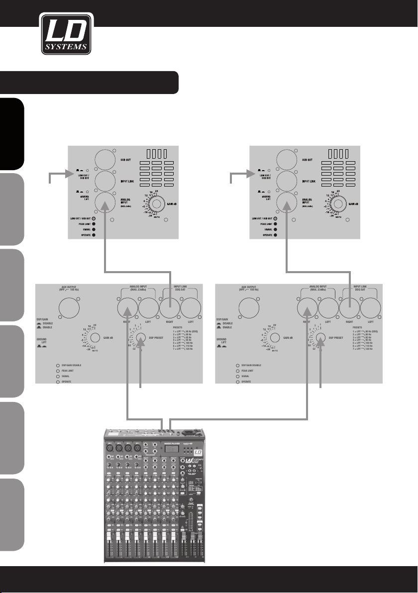
WIRING EXAMPLE :
STEREO SETUP WITH 2 DDQ SUBWOOFERS AND 2 DDQ SATELLITES
ENGLISHDEUTSCHFRANCAIS
LOW CUT/
SUB OUT
activate
DDQ SUB
DSP/GAIN
DISABLE
ENABLE
GROUND
LIFT
ESPAÑOLPOLSKIITALIANO
DDQ satellite
AUX OUTPUT
(HPF 100 Hz)
DSP/GAIN DISABLE
PEAK LIMIT
SIGNAL
OPERATE
GAIN dB
ANALOG INPUT
(MAX. 23dBu)
RIGHT
3
4
5
6
7
A1
A2
B1
B2
C1
D1
C2
Select DSP
Preset 1
1
2
D2
INPUT LINK
DDQ SAT
LEFT RIGHT LEFT
PRESETS
1 = LPF 90 Hz (DDQ)
2 = LPF 80 Hz
3 = LPF 85 Hz
DSP PRESET
4 = LPF 95 Hz
5 = LPF 100 Hz
6 = LPF 110 Hz
7 = LPF 120 Hz
LOW CUT/
SUB OUT
activate
DDQ SUB
DSP/GAIN
DISABLE
ENABLE
GROUND
LIFT
DDQ satellite
AUX OUTPUT
(HPF 100 Hz)
DSP/GAIN DISABLE
PEAK LIMIT
SIGNAL
OPERATE
GAIN dB
ANALOG INPUT
(MAX. 23dBu)
RIGHT
3
4
5
6
7
A1
A2
B1
B2
C1
C2
Select DSP
Preset 1
1
2
D1
D2
INPUT LINK
DDQ SAT
LEFT RIGHT LEFT
PRESETS
1 = LPF 90 Hz (DDQ)
2 = LPF 80 Hz
3 = LPF 85 Hz
DSP PRESET
4 = LPF 95 Hz
5 = LPF 100 Hz
6 = LPF 110 Hz
7 = LPF 120 Hz
FRANCAISFRANCAIS
FRANCAISFRANCAIS
14
Identical setting of the gain controls for the DDQ
subwoofers and DDQ satellites results in linear
frequency response of the overall system (see
illustration Frequency Response). Adjust the
relative volume of the subwoofers and satellites
depending on the space and listening habits.
Page 15
AUX OUTPUT
(HPF 100 Hz)
ANALOG INPUT
(MAX. 23dBu)
RIGHT
GAIN dB
DSP/GAIN DISABLE
PEAK LIMIT
SIGNAL
OPERATE
DSP PRESET
1
D2
2
4
6
A1
B1
C1
D1
3
5
7
A2
B2
C2
LEFT RIGHT LEFT
PRESETS
1 = LPF 90 Hz (DDQ)
2 = LPF 80 Hz
3 = LPF 85 Hz
4 = LPF 95 Hz
5 = LPF 100 Hz
6 = LPF 110 Hz
7 = LPF 120 Hz
CARDIOID SETUP A
REAR FRONT
A2
A1
INPUT LINK
DDQ SAT
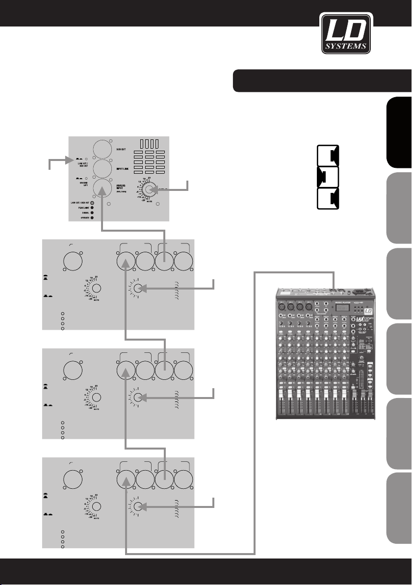
WIRING EXAMPLE :
CARDIOD SETUP B WITH 3 DDQ SUBWOOFERS AND 1 DDQ SATELLITE (1 SIDE)
FRANCAIS
FRANCAIS
ENGLISH
LOW CUT/
SUB OUT
activate
DDQ SUB
DSP/GAIN
DISABLE
ENABLE
GROUND
LIFT
DDQ SUB
DSP/GAIN
DISABLE
ENABLE
GROUND
LIFT
DDQ SUB
DSP/GAIN
DISABLE
ENABLE
GROUND
LIFT
DDQ satellite
AUX OUTPUT
(HPF 100 Hz)
DSP/GAIN DISABLE
PEAK LIMIT
SIGNAL
OPERATE
AUX OUTPUT
(HPF 100 Hz)
DSP/GAIN DISABLE
PEAK LIMIT
SIGNAL
OPERATE
AUX OUTPUT
(HPF 100 Hz)
DSP/GAIN DISABLE
PEAK LIMIT
SIGNAL
OPERATE
GAIN dB
GAIN dB
GAIN dB
RIGHT
RIGHT
RIGHT
ANALOG INPUT
(MAX. 23dBu)
5
6
7
A1
A2
B1
B2
ANALOG INPUT
(MAX. 23dBu)
5
6
7
A1
A2
B1
B2
ANALOG INPUT
(MAX. 23dBu)
5
6
7
A1
A2
B1
B2
3
2
4
C1
D1
C2
3
2
4
C1
D1
C2
3
2
4
C1
D1
C2
INPUT LINK
LEFT RIGHT LEFT
1
PRESETS
1 = LPF 90 Hz (DDQ)
2 = LPF 80 Hz
3 = LPF 85 Hz
DSP PRESET
4 = LPF 95 Hz
5 = LPF 100 Hz
6 = LPF 110 Hz
7 = LPF 120 Hz
D2
INPUT LINK
LEFT RIGHT LEFT
1
PRESETS
1 = LPF 90 Hz (DDQ)
2 = LPF 80 Hz
3 = LPF 85 Hz
DSP PRESET
4 = LPF 95 Hz
5 = LPF 100 Hz
6 = LPF 110 Hz
7 = LPF 120 Hz
D2
INPUT LINK
LEFT RIGHT LEFT
1
PRESETS
1 = LPF 90 Hz (DDQ)
2 = LPF 80 Hz
3 = LPF 85 Hz
DSP PRESET
4 = LPF 95 Hz
5 = LPF 100 Hz
6 = LPF 110 Hz
7 = LPF 120 Hz
D2
Set GAIN to
max. level
DDQ SAT
Select DSP
Preset B1
DDQ SAT
Select DSP
Preset B2
DDQ SAT
Select DSP
Preset B1
CARDIOID SETUP B
B1
REAR FRONT
B2
B1
Middle subwoofer rotated by
180° (see illustration CARDIOID
SETUP B).
Adjust the relative volume between
subwoofers and satellites according
to the space and listening habits,
whereby the volume settings
of the subwoofers must be
identical.
DEUTSCH
FRANCAIS
FRANCAIS
FRANCAIS
ESPAÑOL
POLSKI
ITALIANO
15
Page 16
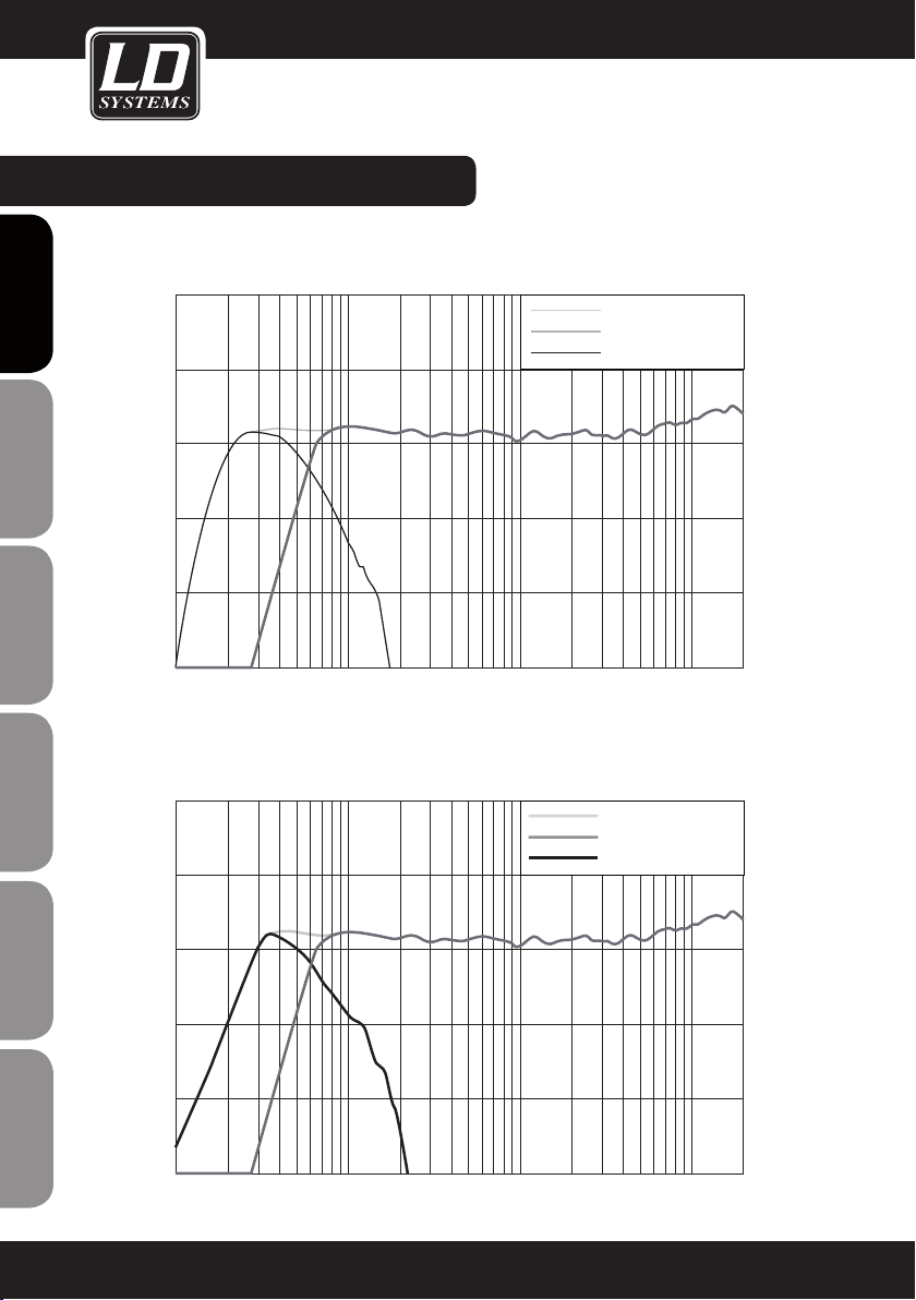
FREQUENCY RESPONSE :
DDQ12 + DDQSUB18
ENGLISHDEUTSCHFRANCAIS
ESPAÑOLPOLSKIITALIANO
-10
-20
-30
dB
10
0
0.05 0.2
dB
10
0.2 0.30.10.030.02
DDQ12 + DDQSUB212
0.5 1 2 5 10 kHz
DDQ12 + DDQSUB18
DDQ12 - Low Cut
DDQSub18
20
DDQ12 + DDQSUB212
DDQ12 - Low Cut
DDQSub212
FRANCAISFRANCAIS
FRANCAISFRANCAIS
16
-10
-20
-30
0
0.05 0.2
0.2 0.30.10.030.02
0.5 1 2 5 10 kHz
20
Page 17
Power
Amps
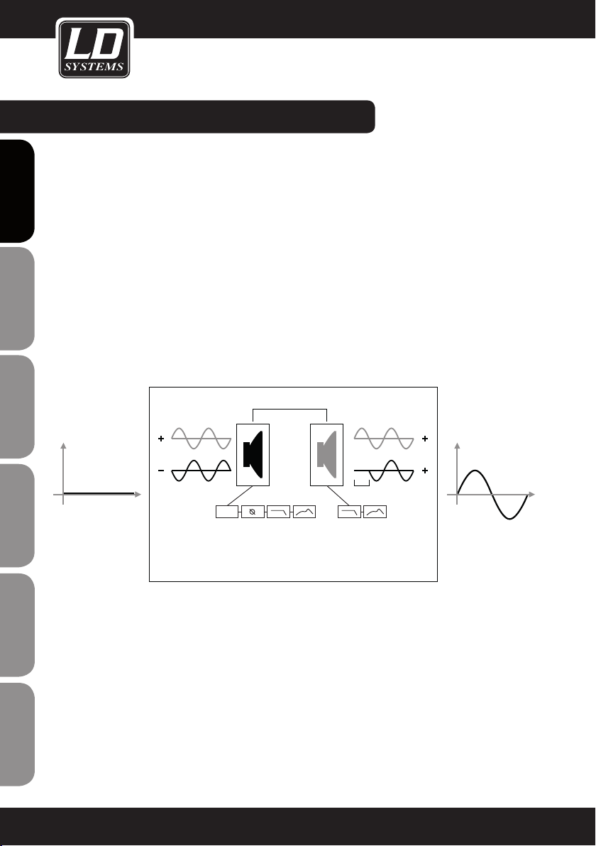
SCHEMATIC DIAGRAM :
2 x
700W
AUX
Output
FRANCAIS
FRANCAIS
ENGLISH
Heat Sink SMPS Amp Power Rail
Onboard PS
+/- 14,4 V Dig Vol.
Temp. Ctr.
μC MUTE Control
Clip Detect Amp
Limiter Decrease
Sharc
1 Ch. DAC
max Level
13,7dBu
113dB Dyn.
1 Ch. Limiter
LS Peak Look ahead (1ms)
LS Thermal limiter
Amp RMS
1 Ch.
High
Pass
/ Low
Pass
1 Ch.
Gain
Delay
IIR EQ
Phase
2 Ch.
Master
Gain
Stacked
1 Ch. DAC
max Level
1 Ch. Limiter
LS Peak Look ahead (1ms)
1 Ch.
High Pass
ADC
24bit /
48kHz
Sens:
18dBu
113dB Dyn.
100Hz /
18dB BW
23dBu
Dyn.
127dB
DEUTSCH
FRANCAIS
FRANCAIS
FRANCAIS
ESPAÑOL
POLSKI
DSP/GAIN
disable
DSP
Preset
GAIN
Encoder
Analog
Input L
Input
Link L
Ʃ
Analog
Input R
Input
ITALIANO
Link R
17
Page 18
SPECIFICATIONS:
Model name
Product type: PA subwoofer PA subwoofer
Type: active active
ENGLISHDEUTSCHFRANCAIS
Version: DSP-controlled DSP-controlled
Woofer size: 2 x 12" 18"
Woofer size: 2 x 304.8 mm 457.2 mm
Woofer magnet: neodymium neodymium
Woofer brand: custom made Faital Pro
Woofer voice coil: 3" 4"
Woofer voice coil: 76.5 mm 101.6 mm
Amplifier: Class D Class D
Power output (RMS): 2 x 700 W 2 x 700 W
Frequency response (Hz): 38 Hz - 120 Hz 30 Hz - 120 Hz
Max. SPL continuous: 124 dB 126 dB
Max. SPL peak: 132 dB 134 dB
Protection: DSP-based "look ahead" limiter,
Input impedance: 10 kohms 10 kohms
Input sensitivity: max. 23 dBu max. 23 dBu
Controls: Gain dB, DSP Preset, Ground Lift,
Indicators: DSP/ Gain disable, Peak Limit,
ESPAÑOLPOLSKIITALIANO
Line inputs: 2 2
Line input connectors: XLR XLR
Line outputs: 3 (2x Input Link, 1x Sat Out with
Line output connectors: XLR XLR
FRANCAISFRANCAIS
FRANCAISFRANCAIS
Power socket: IEC power input and output IEC power input and output
Power supply: switching power supply switching power supply
Operating voltage: 180-264V AC / 47-63 Hz 180-264V AC / 47-63 Hz
Power consumption (max.): 1000 W 1000 W
Cabinet material: 18 mm plywood 18 mm plywood
LDDDQSUB212 LDDDQSUB18
DSP-based "look ahead" limiter,
RMS power supply limiter, RMS
speaker limiter, short circuit,
overvoltage
DSP/Gain enable, Power
Signal, Operate
100Hz high-pass)
RMS power supply limiter, RMS
speaker limiter, short circuit,
overvoltage
Gain dB, DSP Preset, Ground Lift,
DSP/Gain enable, Power
DSP/ Gain disable, Peak Limit,
Signal, Operate
3 (2x Input Link, 1x Sat Out with
100Hz high-pass)
18
Page 19
SPECIFICATIONS:
Cabinet surface: polyurethane polyurethane
Cabinet type: band pass bass reflex
Dimensions (W x H x D): 420 x 620 x 543 mm 510 x 700 x 725 mm
Weight: 34.5 kg 44.5 kg
Other features: 15 x DSP presets with 4 selectable
cardioid setups and 7 selectable
crossover frequencies (80-120Hz),
2 x threaded flange (M20), 3 x corner
handles, prepared for mounting of
casters
15 x DSP presets with 4 selectable
cardioid setups and 7 selectable
crossover frequencies (80-120Hz),
2 x threaded flange (M20), 3 x corner
handles, prepared for mounting of
casters
FRANCAIS
FRANCAIS
ENGLISH
DEUTSCH
FRANCAIS
FRANCAIS
FRANCAIS
ESPAÑOL
POLSKI
ITALIANO
19
Page 20
MANUFACTURER´S DECLARATIONS:
MANUFACTURER‘S WARRANTY
This warranty covers the Adam Hall, LD Systems, Defender, Palmer, and Cameo brands.
It applies to all products distributed by Adam Hall.
ENGLISHDEUTSCHFRANCAIS
This warranty declaration does not affect the statutory warranty claims against the manufacturer, but expands
them with additional warranty claims vis-a-vis Adam Hall.
Adam Hall warrants that the Adam Hall product that you have purchased from Adam Hall or from an Adam Hall
authorized reseller is free from defects in materials or workmanship under normal use for a period of 2 or 5 years
(please inquire on a product-by-product basis) from the date of purchase.
The warranty period begins on the date on which the product was purchased, proof of which must be produced
(through presentation of the invoice or the delivery note with the date of purchase) in the event of a warranty claim.
Should products of the brands named above be in need of repair within the limited warranty period, you are entitled
to warranty service according to the terms and conditions stated here.
During the Limited Warranty Period, Adam Hall will repair or replace the defective component parts or the product.
In the event of repair or replacement during the Limited Warranty Period, the replaced original parts and/or products become property of Adam Hall.
In the unlikely event that the product which you purchased has a recurring failure, Adam Hall has the right, at its
discretion, to replace the defective product with another product, provided that the new product is at least equivalent to the product being replaced with regard to the technical specifications.
Adam Hall does not warrant that the operation of this product will be uninterrupted or error-free. Adam Hall is not
responsible for damage that occurs as a result of your failure to follow the instructions included with the Adam Hall
branded product. The manufacturer‘s warranty does not cover – expendable parts (e. g., rechargeable batteries)
ESPAÑOLPOLSKIITALIANO
- products from which the serial number has been removed or with a serial number that has been damaged as a
result of an accident - damage due to improper use, user error or other external reasons
- damage to devices operated outside the usage parameters stated in the documentation included with the product
- damage due to the use of replacement parts not manufactured, sold or recommended by Adam Hall,
- damage due to modification or servicing by anyone other than Adam Hall.
These terms and conditions constitute the complete and exclusive warranty agreement between you and Adam
Hall regarding the Adam Hall branded product you have purchased.
FRANCAISFRANCAIS
FRANCAISFRANCAIS
20
Page 21
MANUFACTURER´S DECLARATIONS:
LIMITATION OF LIABILITY
If your Adam Hall branded hardware product fails to work as warranted above, your sole and exclusive remedy
shall be repair or replacement. Adam Halls’ maximum liability under this limited warranty is expressly limited to
the lesser of the price you have paid for the product or the cost of repair or replacement of any components that
malfunction under conditions of normal use.
Adam Hall is not liable for any damages caused by the product or the failure of the product, including any lost
profits or savings or special, incidental, or consequential damages. Adam Hall is not liable for any claim made by
a third party or made by you for a third party.
This limitation of liability applies whether damages are sought, or claims are made, under this Limited Warranty
or as a tort claim (including negligence and strict product liability), a contract claim, or any other claim, and
cannot be rescinded or changed by anyone. This limitation of liability will be effective even if you have advised
Adam Hall or an authorized representative of Adam Hall of the possibility of any such damages, but not, however,
in the event of claims for damages in connection with personal injuries.
This manufacturer‘s warranty grants you specific rights; depending on jurisdiction (nation or state), you may be
be entitled to additional claims. You are advised to consult applicable state or national laws for a full determination of your rights.
REQUESTING WARRANTY SERVICE
To request warranty service for the product, contact Adam Hall or the Adam Hall authorized reseller from which
you purchased the product.
FRANCAIS
FRANCAIS
ENGLISH
DEUTSCH
FRANCAIS
FRANCAIS
FRANCAIS
ESPAÑOL
EC DECLARATION OF CONFORMITY
The equipment marketed by Adam Hall complies (where applicable) with the essential requirements and other
relevant specifications of Directives 1999/5/EC (R&TTE), 2004/108/EC (EMC) und 2006/95/EC (LVD). Additional
information can be found at www.adamhall.com.
POLSKI
ITALIANO
21
Page 22
MANUFACTURER´S DECLARATIONS:
PROPER DISPOSAL OF THIS PRODUCT
(Valid in the European Union and other European countries with waste separation)
This symbol on the product, or the documents accompanying the product, indicates that this appliance may not
ENGLISHDEUTSCHFRANCAIS
be treated as household waste. This is to avoid environmental damage or personal injury due to uncontrolled
waste disposal. Please dispose of this product separately from other waste and have it recycled to promote
sustainable economic activity.
Household users should contact either the retailer where they purchased this product, or their local government
office, for details on where and how they can recycle this item in an environmentally friendly manner.
Business users should contact their supplier and check the terms and conditions of the purchase contract. This
product should not be mixed with other commercial wastes for disposal .
ENVIRONMENTAL PROTECTION AND ENERGY CONSERVATION
Energy conservation is an active contribution to environmental protection. Please turn off all unneeded electrical
devices. To prevent unneeded devices from consuming power in standby mode, disconnect the mains plug.
ESPAÑOLPOLSKIITALIANO
FRANCAISFRANCAIS
FRANCAISFRANCAIS
Adam Hall GmbH, all rights reserved. The technical data and the functional product characteristics can be subject
to modifications. The photocopying, the translation, and all other forms of copying of fragments or of the integrlity
of this user’s manual is prohibited.
22
Page 23
FRANCAIS
FRANCAIS
ENGLISH
DEUTSCH
FRANCAIS
FRANCAIS
FRANCAIS
ESPAÑOL
POLSKI
ITALIANO
23
Page 24
ENGLISHDEUTSCHFRANCAIS
Sie haben die richtige Wahl getroffen!
Diese LD Systems Produkte werden Sie lange Jahre durch Zuverlässigkeit, Wirtschaftlichkeit und einfaches
Handling überzeugen. Dafür garantiert LD Systems mit seinem Namen und seiner in vielen Jahren erworbenen
Kompetenz als Hersteller hochwertiger Geräte.
Nehmen Sie sich nun ein paar Minuten Zeit, diese Anleitung zu lesen. Wir möchten, dass Sie einfach
und schnell in den Genuss dieser Technik kommen.
Mehr Informationen zu LD SYSTEMS finden Sie auf unserer Internetseite WWW.LD-SYSTEMS.COM
Einführung
Die LD Systems DDQ-Subwoofer sind leistungsstarke aktive Basslautsprecher mit digitaler Signalbearbeitung für
anspruchsvolle PA-Anwendungen. Sie sind exakt auf die Kombination mit den Fullrange-Lautsprechern der DDQ-
ESPAÑOLPOLSKIITALIANO
Serie abgestimmt und sind ebenso gut für den Einsatz mit Topteilen anderer Hersteller geeignet.
Die kompakten Gehäusekonstruktionen sind mit Neodym-Magnet Lautsprechern bestückt, die von zwei je 700
Watt starken Hypex Class D-Endstufenmodulen mit hocheffizientem Schaltnetzteil und insgesamt 1.400 (2 x 700)
Watt RMS-Leistung angetrieben werden.
Für verzerrungsfreien und sicheren Betrieb, selbst bei höchsten Laustärkepegeln, sorgt der eigens für die DDQ-
FRANCAISFRANCAIS
FRANCAISFRANCAIS
Subwoofer programmierte Sharc-DSP mit 1ms Look Ahead-Limiter, Frequenz- und Phasenkorrektur, sowie allen
Schutzschaltungen und einem weiten Dynamikumfang von 127dB/113 dB (ADC/DAC). 7 DSP Presets ermöglichen
wählbare Trennfrequenzen zwischen 80 und 120Hz. Mit 8 weiteren Presets lassen sich Cardioid-Konfigurationen
aus 2 oder 3 Subwoofern realisieren, womit eine Rückwärtsdämpfung von bis zu 20dB erreicht werden kann. Neben
XLR-Ein- und Ausgängen besitzen die DDQ-Subwoofer einen separaten Mono-Ausgang mit 100Hz Hochpass-Filter.
Weitere Features sind LED-Funktionsanzeigen und ein Ground Lift-Schalter, die Lautstärke- und Preset-Regler
können gegen versehentliches Verstellen gesichert werden.
Die mit extrem widerstandsfähigem Polyurea beschichteten Gehäuse der DDQ-Subwoofer sind aus 18mm
starkem Multiplex gefertigt, mit zwei M20-Gewindeflanschen und ergonomischen Griffen ausgestattet und für die
Montage von Rollen vorbereitet.
24
Page 25
DDQ SERIES
FRANCAIS
FRANCAIS
ENGLISH
AKTIVSUBWOOFER MIT DSP
LDDDQSUB212 / LDDDQSUB18
DEUTSCH
FRANCAIS
FRANCAIS
FRANCAIS
ESPAÑOL
POLSKI
ITALIANO
25
Page 26
SICHERHEITSHINWEISE:
1. Lesen Sie diese Anleitung bitte sorgfältig durch.
2. Bewahren Sie alle Informationen und Anleitungen an einem sicheren Ort auf.
3. Befolgen Sie die Anweisungen.
4. Beachten Sie alle Warnhinweise. Entfernen Sie keine Sicherheitshinweise oder andere Informationen vom Gerät.
5. Verwenden Sie das Gerät nur in der vorgesehenen Art und Weise.
ENGLISHDEUTSCHFRANCAIS
6. Verwenden Sie ausschließlich stabile und passende Stative bzw. Befestigungen (bei Festinstallationen). Stellen
Sie sicher, dass Wandhalterungen ordnungsgemäß installiert und gesichert sind. Stellen Sie sicher, dass das
Gerät sicher installiert ist und nicht herunterfallen kann.
7. Beachten Sie bei der Installation die für Ihr Land geltenden Sicherheitsvorschriften.
8. Installieren und betreiben Sie das Gerät nicht in der Nähe von Heizkörpern, Wärmespeichern, Öfen oder
sonstigen Wärmequellen. Sorgen Sie dafür, dass das Gerät immer so installiert ist, dass es ausreichend gekühlt
wird und nicht überhitzen kann.
9. Platzieren Sie keine Zündquellen wie z.B. brennende Kerzen auf dem Gerät.
10. Lüftungsschlitze dürfen nicht blockiert werden.
11. Betreiben Sie das Gerät nicht in unmittelbarer Nähe von Wasser. Bringen Sie das Gerät nicht mit brennbaren
Materialien, Flüssigkeiten oder Gasen in Berührung.
12. Sorgen Sie dafür, dass kein Tropf- oder Spritzwasser in das Gerät eindringen kann. Stellen Sie keine mit
Flüssigkeit gefüllten Behältnisse wie Vasen oder Trinkgefäße auf das Gerät.
13. Sorgen Sie dafür, dass keine Gegenstände in das Gerät fallen können.
14. Betreiben Sie das Gerät nur mit dem vom Hersteller empfohlenen und vorgesehenen Zubehör.
15. Öffnen Sie das Gerät nicht und verändern Sie es nicht.
16. Überprüfen Sie nach dem Anschluss des Geräts alle Kabelwege, um Schäden oder Unfälle, z. B. durch
Stolperfallen zu vermeiden.
17. Achten Sie beim Transport darauf, dass das Gerät nicht herunterfallen und dabei möglicherweise Sach- und
Personenschäden verursachen kann.
18. Wenn Ihr Gerät nicht mehr ordnungsgemäß funktioniert, Flüssigkeiten oder Gegenstände in das Geräteinnere
gelangt sind, oder das Gerät anderweitig beschädigt wurde, schalten Sie es sofort aus und trennen es von der
Netzsteckdose (sofern es sich um ein aktives Gerät handelt). Dieses Gerät darf nur von autorisiertem Fachperso-
ESPAÑOLPOLSKIITALIANO
nal repariert werden.
19. Verwenden Sie zur Reinigung des Geräts ein trockenes Tuch.
20. Beachten Sie alle in Ihrem Land geltenden Entsorgungsgesetze. Trennen Sie bei der Entsorgung der Verpackung bitte Kunststoff und Papier bzw. Kartonagen voneinander.
21. Kunststoffbeutel müssen außer Reichweite von Kindern aufbewahrt werden.
BEI GERÄTEN MIT NETZANSCHLUSS:
FRANCAISFRANCAIS
FRANCAISFRANCAIS
22. ACHTUNG: Wenn das Netzkabel des Geräts mit einem Schutzkontakt ausgestattet ist, muss es an einer
Steckdose mit Schutzleiter angeschlossen werden. Deaktivieren Sie niemals den Schutzleiter eines Netzkabels.
23. Schalten Sie das Gerät nicht sofort ein, wenn es starken Temperaturschwankungen ausgesetzt war (beispielsweise nach dem Transport). Feuchtigkeit und Kondensat könnten das Gerät beschädigen. Schalten Sie das
Gerät erst ein, wenn es Zimmertemperatur erreicht hat.
24. Bevor Sie das Gerät an die Steckdose anschließen, prüfen Sie zuerst, ob die Spannung und die Frequenz
des Stromnetzes mit den auf dem Gerät angegebenen Werten übereinstimmen. Verfügt das Gerät über einen
Spannungswahlschalter, schließen Sie das Gerät nur an die Steckdose an, wenn die Gerätewerte mit den Werten
des Stromnetzes übereinstimmen. Wenn das mitgelieferte Netzkabel bzw. der mitgelieferte Netzadapter nicht in
Ihre Netzsteckdose passt, wenden Sie sich an Ihren Elektriker.
25. Treten Sie nicht auf das Netzkabel. Sorgen Sie dafür, dass spannungsführende Kabel speziell an der Netz-
26
Page 27
SICHERHEITSHINWEISE:
buchse bzw. am Netzadapter und der Gerätebuchse nicht geknickt werden.
26. Achten Sie bei der Verkabelung des Geräts immer darauf, dass das Netzkabel bzw. der Netzadapter stets frei
zugänglich ist. Trennen Sie das Gerät stets von der Stromzuführung, wenn das Gerät nicht benutzt wird, oder
Sie das Gerät reinigen möchten. Ziehen Sie Netzkabel und Netzadapter immer am Stecker bzw. am Adapter und
nicht am Kabel aus der Steckdose. Berühren Sie Netzkabel und Netzadapter niemals mit nassen Händen.
27. Schalten Sie das Gerät möglichst nicht schnell hintereinander ein und aus, da sonst die Lebensdauer des
Geräts beeinträchtigt werden könnte.
28. WICHTIGER HINWEIS: Ersetzen Sie Sicherungen ausschließlich durch Sicherungen des gleichen Typs und
Wertes. Sollte eine Sicherung wiederholt auslösen, wenden Sie sich bitte an ein autorisiertes Servicezentrum.
29. Um das Gerät vollständig vom Stromnetz zu trennen, entfernen Sie das Netzkabel bzw. den Netzadapter aus
der Steckdose.
30. Wenn Ihr Gerät mit einem verriegelbaren Netzanschluss bestückt ist, muss der passende Gerätestecker
entsperrt werden, bevor er entfernt werden kann. Das bedeutet aber auch, dass das Gerät durch ein Ziehen am
Netzkabel verrutschen und herunterfallen kann, wodurch Personen verletzt werden und/oder andere Schäden
auftreten können. Verlegen Sie Ihre Kabel daher immer sorgfältig.
31. Entfernen Sie Netzkabel und Netzadapter aus der Steckdose bei Gefahr eines Blitzschlags oder wenn Sie das
Gerät länger nicht verwenden.
CAUTION
RISK OF ELECTRIC SHOCK
DO NOT OPEN
ACHTUNG:
Entfernen Sie niemals die Abdeckung, da sonst das Risiko eines elektrischen Schlages besteht. Im Inneren des
Geräts befinden sich keine Teile, die vom Bediener repariert oder gewartet werden können. Lassen Sie Reparaturen ausschließlich von qualifiziertem Servicepersonal durchführen.
Das gleichschenkelige Dreieck mit Blitzsymbol warnt vor nichtisolierten, gefährlichen Spannungen
im Geräteinneren, die einen elektrischen Schlag verursachen können.
Das gleichschenkelige Dreieck mit Ausrufungszeichen kennzeichnet wichtige Bedienungs- und
Wartungshinweise.
FRANCAIS
FRANCAIS
ENGLISH
ENGLISH
DEUTSCH
FRANCAIS
FRANCAIS
FRANCAIS
ESPAÑOL
ACHTUNG HOHE LAUTSTÄRKEN BEI AUDIOPRODUKTEN!
Dieses Gerät ist für den professionellen Einsatz vorgesehen. Der kommerzielle Betrieb dieses Geräts unterliegt
den jeweils gültigen nationalen Vorschriften und Richtlinien zur Unfallverhütung. Als Hersteller ist Adam Hall
gesetzlich verpflichtet, Sie ausdrücklich auf mögliche Gesundheitsrisiken hinzuweisen.
Gehörschäden durch hohe Lautstärken und Dauerbelastung: Bei der Verwendung dieses Produkts können
hohe Schalldruckpegel (SPL) erzeugt werden, die bei Künstlern, Mitarbeitern und Zuschauern zu irreparablen
Gehörschäden führen können. Vermeiden Sie länger anhaltende Belastung durch hohe Lautstärken über 90 dB.
VORSICHT! WICHTIGE HINWEISE IN BEZUG AUF LICHT-PRODUKTE
1. Blicken Sie nicht aus Entfernungen von unter 40 cm in den Lichtstrahl.
2. Blicken Sie niemals längere Zeit aus kurzem bis mittlerem Abstand in den Lichtstrahl.
3. Blicken Sie niemals mit optischen Geräten wie Vergrößerungsgläsern in den Lichtstrahl.
4. Stoboskopeffekte können unter Umständen bei empfindlichen Menschen epileptische Anfälle auslösen! Epilepsiekranke Menschen sollten daher unbedingt Orte meiden, an denen Stroboskope eingesetzt werden.
POLSKI
ITALIANO
27
Page 28
DDQSUB CARDIOID TECHNOLOGIE:
Die DDQSub Cardioid Technologie ermöglicht es, durch den Einsatz gezielter DSP Programmierung das Abstrahlverhalten eines Subwoofer Setups zu beeinflussen. So ist es möglich, im Subbass-Frequenzbereich aus einer annähernd
omnidirektionalen Abstrahlcharakteristik eine nierenförmigen Abstrahlung einzustellen. Dazu sind mindestens 2 Subwoofer
ENGLISHDEUTSCHFRANCAIS
des gleichen Typs erforderlich. Dadurch dass einer der Subwoofer innerhalb eines Cardioid-Setups um 180° gedreht aufgebaut, oder räumlich versetzt wird, kann mittels Laufzeit- und Amplituden-Korrektur die abgestrahlte Schallenergie hinter
dem Bass-Array weitgehend minimiert werden. Erreicht wird das in dem die Subwoofer in einer von 4 möglichen Setups
aufgestellt werden und für jeden Subwoofer eines der voreingestellten DSP Programme aufgerufen wird.
SCHEMATISCHE DARSTELLUNG EINES CARDIOID SUBWOOFER-ARRAYS MIT FUNKTIONSWEISE UND
AUSWIRKUNG
d = λ/4
Rear Front
= 2* λ/4
Δt
Laufzeit
Phase
Crossover / GainEQCrossover / Gain
ESPAÑOLPOLSKIITALIANO
EQ
Die durch die räumlich getrennte Aufstellung der Subwoofer entsteht ein Laufzeitunterschied zwischen vorderem
FRANCAISFRANCAIS
FRANCAISFRANCAIS
und hinterem Subwoofer. Dieser Unterschied wird innerhalb des DSP Presets durch Laufzeit-, Amplituden- und
Phasenkorrektur so angepasst, dass sich in Abstrahlrichtung nach vorne die maximale Addition der Schallwellen
ergibt. Auf der Rückseite des Subwoofer-Arrays entsteht bei gleicher Einstellung eine Auslöschung der Schallwellen
und erzeugt damit die gewünschte Rückwärtsdämpfung des Gesamtsystems.
28
Page 29
Frequency [kHz]
Rear
Frequency [kHz]
Rear
DDQSUB CARDIOID TECHNOLOGIE:
FRANCAIS
FRANCAIS
ABSTRAHLVERHALTEN EINES KONVENTIONELLEN
SUBWOOFER SETUPS (vereinfachte Darstellung)
180°
VERWENDUNG DER DDQ SUBWOOFER ALS
CARDIOID-SUBWOOFER ARRAY
Bei den DSP-Presets A1 - D2 handelt es sich um aufwändige DSP-Programmierungen, die es ermöglichen,
ein nierenförmig gerichtetes Abstrahlverhalten (Cardioid)
120°
durch eine Kombination aus 2 oder 3 DDQ Subwoofern
zu erreichen.
60°
Dadruch egeben sich folgende Vorteile gegenüber
konventionellen Subwoofer Setups:
0°
Front
-eine Rückwärtsdämpfung von bis zu 20 dB
-eine präzisere Bassreproduktion im Zuhörerbereich
-60°
-die Vermeidung ungewollter Reflexionen von Rückwänden
-die Verringerung von Diffusschall in Räumen
-der Wegfall störender Bassfrequenzen auf der Bühne
-120°
-differenziertes Klangbild für die Bühnenbeschallung
(Monitoring)
-Verminderung der Rückkopplungsgefahr beim Einsatz
-180°
Rear
0,1 0,2 0,50,02 0,05
von Bühnenmikrofonen
Verwenden Sie für Cardioid Setups ausschließlich DDQ
Subwoofer des gleichen Typs.
ABSTRAHLVERHALTEN EINES CARDIOID SUBWOOFER-ARRAYS (vereinfachte Darstellung)
180°
An allen für ein Cardioid Setup verwendeten Subwoofern
muss das selbe Audiosignal anliegen.
Die Einstellung der GAIN-Regler an allen für ein Cardioid
Setup verwendeten Subwoofern muss identisch sein.
Die DSP-Preset Einstellung muss individuell für jeden
120°
Subwoofer eingestellt werden.
Ob der Subwoofer stehend oder liegend betrieben wird
60°
ist für die Funktion der Cardiod Presets unerheblich.
ENGLISH
DEUTSCH
FRANCAIS
FRANCAIS
FRANCAIS
ESPAÑOL
POLSKI
Front
Rear
-120°
-180°
0°
-60°
0,1 0,2 0,50,02 0,05
ITALIANO
29
Page 30
ANSCHLÜSSE, BEDIEN- UND ANZEIGEELEMENTE:
ENGLISHDEUTSCHFRANCAIS
6
7
ESPAÑOLPOLSKIITALIANO
FRANCAISFRANCAIS
FRANCAISFRANCAIS
DSP/GAIN
DISABLE
ENABLE
GROUND
LIFT
8
9
10
11
AUX OUTPUT
(HPF 100 Hz)
3
DSP/GAIN DISABLE
PEAK LIMIT
SIGNAL
OPERATE
ANALOG INPUT
(MAX. 23dBu)
INPUT LINK
DDQ SAT
21
RIGHT
GAIN dB
4
7
A2
B2
LEFT RIGHT LEFT
1
3
2
4
5
6
A1
B1
DSP PRESET
5
C1
D1
C2
D2
PRESETS
1 = LPF 90 Hz (DDQ)
2 = LPF 80 Hz
3 = LPF 85 Hz
4 = LPF 95 Hz
5 = LPF 100 Hz
6 = LPF 110 Hz
7 = LPF 120 Hz
30
Page 31

ANSCHLÜSSE, BEDIEN- UND ANZEIGEELEMENTE:
1
ANALOG INPUT LEFT/RIGHT
Symmetrische XLR Line-Eingänge links und rechts.
Um einen Subwoofer mit zwei Satellitenlautsprechern als Stereo-Beschallungsanlage zu betreiben, verbinden
Sie die Ausgänge links und rechts des Zuspielgeräts (z.B. Mischpult) mit den Eingängen links und rechts des
Subwoofers (ANALOG INPUT LEFT/RIGHT). Verbinden Sie nun den linken Ausgang des Subwoofers (INPUT LINK
LEFT) mit dem aktiven Satellitenlautsprecher auf der linken Seite und den rechten Ausgang des Subwoofers
(INPUT LINK RIGHT) mit dem aktiven Satellitenlautsprecher auf der rechten Seite. Das Signal für den Subwoofer
wird aus dem Stereo-Eingangssignal als Mono-Summe gebildet.
Um zwei Subwoofer mit zwei Satellitenlautsprechern als Stereo-Beschallungsanlage zu betreiben, verbinden Sie
Ausgangsbuchse links des Zuspielgeräts mit einer Eingangsbuchse des Subwoofers auf der linken Seite (ANALOG
INPUT LEFT oder RIGHT). Wenn Sie die linke Eingangsbuchse gewählt haben (ANALOG INPUT LEFT), müssen Sie
nun auch die linke Ausgangsbuchse (INPUT LINK LEFT) für die Verkabelung des Satellitelautsprechers auf der linken
Seite verwenden und umgekehrt. Verfahren Sie in gleicher Weise mit der rechten Ausgangsbuchse des Zuspielgeräts und dem Subwoofer mit Satellitenlautsprecher auf der rechten Seite. Verwenden Sie für die Verkabelung
ausschließlich symmetrische XLR-Kabel.
2
INPUT LINK - DDQ SAT LEFT/RIGHT
Symmetrische XLR-Ausgänge links und rechts. An den INPUT LINK Ausgangsbuchsen liegt das selbe Signal an,
wie an den ANALOG INPUT Eingangsbuchsen. Werden LD Systems DDQ Fullrange-Lausprecher als Satellitenlautsprecher an den DDQ Subwoofern betrieben, müssen die INPUT LINK Ausgangsbuchsen zur Ansteuerung
verwendet werden, da die DDQ Fullrange-Lautsprecher über ein schaltbares Hochpass-Filter verfügen.
3
AUX OUTPUT
Symmetrischer XLR-Ausgang mit 100 Hz Hochpass-Filter (Mono-Summe aus den Eingangssignalen links und
rechts). Für die Verwendung aktiver Fullrange-Lautsprecher, die nicht über ein Hochpass-Filter verfügen.
FRANCAIS
FRANCAIS
ENGLISH
DEUTSCH
FRANCAIS
FRANCAIS
FRANCAIS
ESPAÑOL
4
GAIN DB
Regler für die Eingangsempfindlichkeit, respektive die Lautstärke des Verstärker-Moduls. Bei Überschreitung
des maximalen Eingangspegels (23 dBu) wird dies durch gemeinsames Blinken der LEDs 8-11 signalisiert.
Verringern Sie in diesem Fall den Pegel der Signalquelle, um Klangbeeinträchtigungen zu vermeiden.
5
DSP PRESET
Bei den DSP-Presets 1 - 7 handelt es sich um DSP-Programmierungen, bei denen unterschiedliche
Tiefpass-Filter (LPF) im Subwoofer-Kanal gesetzt sind.
Preset 1: Tiefpass-Filter (LPF) 90 Hz. Verwendung mit Lautsprechern der LD Systems DDQ Fullrange-Serie.
Preset 2: Tiefpass-Filter (LPF) 80 Hz.
Preset 3: Tiefpass-Filter (LPF) 85 Hz.
Preset 4: Tiefpass-Filter (LPF) 95 Hz.
Preset 5: Tiefpass-Filter (LPF) 100 Hz.
Preset 6: Tiefpass-Filter (LPF) 110 Hz.
Preset 7: Tiefpass-Filter (LPF) 120 Hz.
POLSKI
ITALIANO
31
Page 32

AUX OUTPUT
(HPF 100 Hz)
ANALOG INPUT
(MAX. 23dBu)
RIGHT
GAIN dB
DSP/GAIN DISABLE
PEAK LIMIT
SIGNAL
OPERATE
DSP PRESET
1
D2
2
4
6
A1
B1
C1
D1
3
5
7
A2
B2
C2
LEFT RIGHT LEFT
PRESETS
1 = LPF 90 Hz (DDQ)
2 = LPF 80 Hz
3 = LPF 85 Hz
4 = LPF 95 Hz
5 = LPF 100 Hz
6 = LPF 110 Hz
7 = LPF 120 Hz
INPUT LINK
DDQ SAT
AUX OUTPUT
(HPF 100 Hz)
ANALOG INPUT
(MAX. 23dBu)
RIGHT
GAIN dB
DSP/GAIN DISABLE
PEAK LIMIT
SIGNAL
OPERATE
DSP PRESET
1
D2
2
4
6
A1
B1
C1
D1
3
5
7
A2
B2
C2
LEFT RIGHT LEFT
PRESETS
1 = LPF 90 Hz (DDQ)
2 = LPF 80 Hz
3 = LPF 85 Hz
4 = LPF 95 Hz
5 = LPF 100 Hz
6 = LPF 110 Hz
7 = LPF 120 Hz
CARDIOID SETUP A
REAR FRONT
A2
A1
INPUT LINK
DDQ SAT
RIGHT
GAIN dB
DSP/GAIN DISABLE
PEAK LIMIT
SIGNAL
OPERATE
DSP PRESET
1
D2
2
4
6
A1
B1
C1
D1
3
5
7
A2
B2
C2
LEFT RIGHT LEFT
PRESETS
1 = LPF 90 Hz (DDQ)
2 = LPF 80 Hz
3 = LPF 85 Hz
4 = LPF 95 Hz
5 = LPF 100 Hz
6 = LPF 110 Hz
7 = LPF 120 Hz
CARDIOID SETUP A
CARDIOID SETUP B
REAR FRONT
REAR FRONT
A2
B2
A1
B1
B1
RIGHT
GAIN dB
DSP/GAIN DISABLE
PEAK LIMIT
SIGNAL
OPERATE
DSP PRESET
1
D2
2
4
6
A1
B1
C1
D1
3
5
7
A2
B2
C2
LEFT RIGHT LEFT
PRESETS
1 = LPF 90 Hz (DDQ)
2 = LPF 80 Hz
3 = LPF 85 Hz
4 = LPF 95 Hz
5 = LPF 100 Hz
6 = LPF 110 Hz
7 = LPF 120 Hz
CARDIOID SETUP A
CARDIOID SETUP B
CARDIOID SETUP C
REAR FRONT
REAR FRONT
LEFT RIGHT
A2
B2
A1
B1
B1
C1 C1C2
ANSCHLÜSSE, BEDIEN- UND ANZEIGEELEMENTE:
5
DSP PRESET
ENGLISHDEUTSCHFRANCAIS
ESPAÑOLPOLSKIITALIANO
FRANCAISFRANCAIS
FRANCAISFRANCAIS
CARDIOID SETUP A (PRESET A1 UND A2):
Stellen Sie 2 DDQ Subwoofer so übereinander, dass
der obere Subwoofer um 180° gedreht zum unteren Subwoofer nach hinten gerichtet steht (siehe
Abbildung CARDIOID SETUP A). Wählen Sie beim
unteren, nach vorn gerichteten Subwoofer Preset
A1 und beim oberen, nach hinten gerichteten
Subwoofer Preset A2.
CARDIOID SETUP B (PRESET B1 UND B2):
Stellen Sie 3 DDQ Subwoofer so übereinander,
dass der mittlere Subwoofer um 180° gedreht
zu den anderen nach hinten gerichtet steht
(siehe Abbildung CARDIOID SETUP B). Wählen Sie
beim unteren und oberen, nach vorn gerichteten
Subwoofern Preset B1 und beim mittleren, nach
hinten gerichteten Subwoofer Preset B2.
CARDIOID SETUP C (PRESET C1 UND C2):
Stellen Sie 3 DDQ Subwoofer so nebeneinander,
dass der mittlere Subwoofer um 180° gedreht zu
den anderen nach hinten gerichtet steht (siehe
Abbildung CARDIOID SETUP C). Wählen Sie bei
dem linken und rechten, nach vorn gerichteten
Subwoofern Preset C1 und beim mittleren, nach
hinten gerichteten Subwoofer Preset C2.
CARDIOID SETUP D (PRESET D1 UND D2):
Stellen Sie 2 DDQ Subwoofer so hintereinander,
dass beide Subwoofer nach vorn gerichtet auf
der gleichen Achse stehen und die Distanz der
Vorderkanten beider Subwoofer 1 Meter beträgt
(siehe Abbildung CARDIOID SETUP D). Wählen Sie
beim vorderen Subwoofer Preset D1 und beim
hinteren Preset D2.
WICHTIG: Die Einstellung des GAIN-Reglers muss
bei allen für ein Cardioid Setup verwendeten
Subwoofern identisch sein!
SEITENANSICHT
REAR FRONT
CARDIOID SETUP A
A1
CARDIOID SETUP B
A2
B1
REAR FRONT
ANSICHT VON VORN
B2
B1
CARDIOID SETUP C
LEFT RIGHT
C1 C1C2
SEITENANSICHT
CARDIOID SETUP D
REAR FRONT
D2 D1
1m
32
Page 33

ANSCHLÜSSE, BEDIEN- UND ANZEIGEELEMENTE:
6
DSP/GAIN ENABLE/DISABLE
Durch das Herunterdrücken dieses Schalters wird ein unbeabsichtigtes Verstellen von Preset und GainEinstellung verhindert, indem beide Encoder GAIN dB und DSP PRESET außer Funktion gesetzt werden (DSP/
GAIN DISABLE). Ist der Schalter aktiviert, leuchtet die dazugehörende DSP/GAIN DISABLE LED auf. Beim
Deaktivieren der Funktion (DSP/GAIN DISABLE LED leuchtet nicht) wird die aktuell an GAIN und PRESET
Encodern eingestellten Werte in den DSP geladen und die beiden Bedienelemente wieder freigegeben.
7
GROUND LIFT
Schalter in heruntergedrückter Position kann Brummschleifen verhindern, sobald Geräte mit unterschiedlichem
Erdungspotential angeschlossen werden.
8
DSP/GAIN DISABLE LED
Leuchtet auf, sobald der Schalter DSP/GAIN ENABLE/DISABLE heruntergedrückt ist (DSP/GAIN DISABLE). In
diesem Zustand sind die beiden Encoder GAIN dB und DSP PRESET ausser Funktion.
9
PEAK LIMIT LED
Leuchtet auf, sobald der Subwoofer im Grenzbereich betrieben wird. Kurzzeitiges Aufleuchten ist dabei unkritisch,
da der interne Audio-Limiter Übersteuerungen ausregelt. Dauerhaftes Leuchten sollte durch Absenken des Eingangspegels vermieden werden.
10
SIGNAL LED
Leuchtet auf, sobald ein Audiosignal am Line-Eingang anliegt (> -30dBu).
11
OPERATE LED
Leuchtet auf, sobald der Subwoofer eingeschaltet und korrekt am Stromnetz angeschlossen ist.
FRANCAIS
FRANCAIS
ENGLISH
DEUTSCH
FRANCAIS
FRANCAIS
FRANCAIS
ESPAÑOL
POLSKI
ITALIANO
33
Page 34

DSP/GAIN DISABLE
PEAK LIMIT
SIGNAL
OPERATE
D2
B1
C1
D1
A2
B2
C2
4 = LPF 95 Hz
5 = LPF 100 Hz
6 = LPF 110 Hz
7 = LPF 120 Hz
CARDIOID SETUP A
CARDIOID SETUP B
CARDIOID SETUP C
CARDIOID SETUP D
REAR FRONT
REAR FRONT
LEFT RIGHT
REAR FRONT
GROUND
LIFT
A2
B2
A1
B1
B1
C1 C1C2
DDO SUB18
1m
D2 D1
ANSCHLÜSSE, BEDIEN- UND ANZEIGEELEMENTE:
14
ENGLISHDEUTSCHFRANCAIS
90-160V~ / 47-63 Hz
180-264V~ / 47-63 Hz
MAXIMUM POWER 1000W
12
12
IEC NETZEINGANGSBUCHSE (VERRIEGELBAR)
Stellen Sie VOR Inbetriebnahme sicher, dass die Netzspannung Ihres Energieversorgers und die Betriebsspannung
des Geräts übereinstimmen!
13
POWER
13
POWER
LD-SYSTEMS® is a registered Brand of Adam Hall Germany
Daimlerstr. 9 • 61267 Neu-Anspach
RISC OF ELECTRIC
SHOCK. DO NOT OPEN!
DO NOT BLOCK
VENTILATION HOLES
Ein- / Ausschalter. Vor dem Ein- und Ausschalten stets die Lautstärke auf Minimum stellen (GAIN-Regler 4 auf
Linksanschlag). Um Ein- und Ausschaltgeräusche zu vermeiden, empfiehlt es sich, Lautsprecher immer als
letztes Glied einer Beschallungsanlage ein- und als Erstes auszuschalten.
TO PREVENT FIRE OR
SHOCK HAZARD, DO
NOT EXPOSE THIS
APPLIANCE TO RAIN
OR MOISTURE
14
ESPAÑOLPOLSKIITALIANO
FRANCAISFRANCAIS
FRANCAISFRANCAIS
34
IEC NETZAUSGANGSBUCHSE
Die Summe der Leistungsaufnahme der angeschlossenen Geräte darf den maximalen Anschlusswert nicht
überschreiten.
Page 35

STEREO SETUP MIT 1 DDQ SUBWOOFER UND 2 DDQ TOPTEILEN
DDQ Topteil DDQ Topteil
LOW CUT/
SUB OUT
aktivieren
LOW CUT/
SUB OUT
aktivieren
FRANCAIS
FRANCAIS
ENGLISH
DEUTSCH
FRANCAIS
FRANCAIS
FRANCAIS
ESPAÑOL
DDQ SUB
DSP/GAIN
DISABLE
ENABLE
GROUND
LIFT
AUX OUTPUT
(HPF 100 Hz)
DSP/GAIN DISABLE
PEAK LIMIT
SIGNAL
OPERATE
GAIN dB
RIGHT
7
A2
ANALOG INPUT
(MAX. 23dBu)
3
4
5
6
A1
B1
B2
C1
C2
1
2
D1
D2
LEFT RIGHT LEFT
DSP PRESET
INPUT LINK
DDQ SAT
PRESETS
1 = LPF 90 Hz (DDQ)
2 = LPF 80 Hz
3 = LPF 85 Hz
4 = LPF 95 Hz
5 = LPF 100 Hz
6 = LPF 110 Hz
7 = LPF 120 Hz
DSP Preset
1 wählen
Das Lautstärkenverhältnis zwischen Subwoofer und Topteilen ist je nach Räumlichkeit und Hörgewohnheit einzustellen.
POLSKI
ITALIANO
35
Page 36

VERKABELUNGSBEISPIEL :
STEREO SETUP MIT 2 DDQ SUBWOOFERN UND 2 DDQ TOPTEILEN
ENGLISHDEUTSCHFRANCAIS
LOW CUT/
SUB OUT
aktivieren
DDQ SUB
DSP/GAIN
DISABLE
ENABLE
GROUND
LIFT
ESPAÑOLPOLSKIITALIANO
DDQ Topteil
AUX OUTPUT
(HPF 100 Hz)
DSP/GAIN DISABLE
PEAK LIMIT
SIGNAL
OPERATE
GAIN dB
ANALOG INPUT
(MAX. 23dBu)
RIGHT
3
4
5
6
7
A1
A2
B1
B2
C1
D1
C2
DSP Preset
1 wählen
1
2
D2
INPUT LINK
DDQ SAT
LEFT RIGHT LEFT
PRESETS
1 = LPF 90 Hz (DDQ)
2 = LPF 80 Hz
3 = LPF 85 Hz
DSP PRESET
4 = LPF 95 Hz
5 = LPF 100 Hz
6 = LPF 110 Hz
7 = LPF 120 Hz
LOW CUT/
SUB OUT
aktivieren
DDQ SUB
DSP/GAIN
DISABLE
ENABLE
GROUND
LIFT
DDQ Topteil
AUX OUTPUT
(HPF 100 Hz)
DSP/GAIN DISABLE
PEAK LIMIT
SIGNAL
OPERATE
GAIN dB
ANALOG INPUT
(MAX. 23dBu)
RIGHT
3
2
4
5
6
7
A1
A2
B1
B2
C1
D1
C2
DSP Preset
1 wählen
1
D2
INPUT LINK
DDQ SAT
LEFT RIGHT LEFT
PRESETS
1 = LPF 90 Hz (DDQ)
2 = LPF 80 Hz
3 = LPF 85 Hz
DSP PRESET
4 = LPF 95 Hz
5 = LPF 100 Hz
6 = LPF 110 Hz
7 = LPF 120 Hz
FRANCAISFRANCAIS
FRANCAISFRANCAIS
36
Gleiche Einstellung des Gain Encoders bei DDQ
Subwoofer und DDQ Topteil führt zu einem linearen Frequenzgang des Gesamtsystems (siehe Abbildung Frequenzgang). Das Lautstärkenverhältnis
zwischen Subwoofern und Topteilen ist je nach
Räumlichkeit und Hörgewohnheit einzustellen.
Page 37

AUX OUTPUT
(HPF 100 Hz)
ANALOG INPUT
(MAX. 23dBu)
RIGHT
GAIN dB
DSP/GAIN DISABLE
PEAK LIMIT
SIGNAL
OPERATE
DSP PRESET
1
D2
2
4
6
A1
B1
C1
D1
3
5
7
A2
B2
C2
LEFT RIGHT LEFT
PRESETS
1 = LPF 90 Hz (DDQ)
2 = LPF 80 Hz
3 = LPF 85 Hz
4 = LPF 95 Hz
5 = LPF 100 Hz
6 = LPF 110 Hz
7 = LPF 120 Hz
CARDIOID SETUP A
REAR FRONT
A2
A1
INPUT LINK
DDQ SAT
VERKABELUNGSBEISPIEL :
CARDIOD SETUP B MIT 3 DDQ SUBWOOFERN UND 1 DDQ TOPTEIL (1 SEITE)
FRANCAIS
FRANCAIS
ENGLISH
LOW CUT/
SUB OUT
aktivieren
DDQ SUB
DSP/GAIN
DISABLE
ENABLE
GROUND
LIFT
DDQ SUB
DSP/GAIN
DISABLE
ENABLE
GROUND
LIFT
DDQ SUB
DSP/GAIN
DISABLE
ENABLE
GROUND
LIFT
DDQ Topteil
AUX OUTPUT
(HPF 100 Hz)
DSP/GAIN DISABLE
PEAK LIMIT
SIGNAL
OPERATE
AUX OUTPUT
(HPF 100 Hz)
DSP/GAIN DISABLE
PEAK LIMIT
SIGNAL
OPERATE
AUX OUTPUT
(HPF 100 Hz)
DSP/GAIN DISABLE
PEAK LIMIT
SIGNAL
OPERATE
GAIN dB
GAIN dB
GAIN dB
RIGHT
RIGHT
RIGHT
ANALOG INPUT
(MAX. 23dBu)
5
6
7
A1
A2
B1
B2
ANALOG INPUT
(MAX. 23dBu)
5
6
7
A1
A2
B1
B2
ANALOG INPUT
(MAX. 23dBu)
5
6
7
A1
A2
B1
B2
3
2
4
C1
D1
C2
3
2
4
C1
D1
C2
3
2
4
C1
D1
C2
INPUT LINK
LEFT RIGHT LEFT
1
PRESETS
1 = LPF 90 Hz (DDQ)
2 = LPF 80 Hz
3 = LPF 85 Hz
DSP PRESET
4 = LPF 95 Hz
5 = LPF 100 Hz
6 = LPF 110 Hz
7 = LPF 120 Hz
D2
INPUT LINK
LEFT RIGHT LEFT
1
PRESETS
1 = LPF 90 Hz (DDQ)
2 = LPF 80 Hz
3 = LPF 85 Hz
DSP PRESET
4 = LPF 95 Hz
5 = LPF 100 Hz
6 = LPF 110 Hz
7 = LPF 120 Hz
D2
INPUT LINK
LEFT RIGHT LEFT
1
PRESETS
1 = LPF 90 Hz (DDQ)
2 = LPF 80 Hz
3 = LPF 85 Hz
DSP PRESET
4 = LPF 95 Hz
5 = LPF 100 Hz
6 = LPF 110 Hz
7 = LPF 120 Hz
D2
GAIN auf
max. Pegel
einstellen
DDQ SAT
DSP Preset
B1 wählen
DDQ SAT
DSP Preset
B2 wählen
DDQ SAT
DSP Preset
B1 wählen
CARDIOID SETUP B
B1
REAR FRONT
B2
B1
Mittlerer Subwoofer um 180°
gedreht (siehe Abbildung
CARDIOID SETUP B).
Das Lautstärkenverhältnis
zwischen Subwoofern und
Topteilen ist je nach Räumlichkeit
und Hörgewohnheit einzustellen,
wobei die Lautstärkeneinstellung der Subwoofer
identisch sein muss.
DEUTSCH
FRANCAIS
FRANCAIS
FRANCAIS
ESPAÑOL
POLSKI
ITALIANO
37
Page 38

FREQUENZGANG :
DDQ12 + DDQSUB18
ENGLISHDEUTSCHFRANCAIS
ESPAÑOLPOLSKIITALIANO
-10
-20
-30
dB
10
0
0.05 0.2
dB
10
0.2 0.30.10.030.02
DDQ12 + DDQSUB212
0.5 1 2 5 10 kHz
DDQ12 + DDQSUB18
DDQ12 - Low Cut
DDQSub18
20
DDQ12 + DDQSUB212
DDQ12 - Low Cut
DDQSub212
FRANCAISFRANCAIS
FRANCAISFRANCAIS
38
-10
-20
-30
0
0.05 0.2
0.2 0.30.10.030.02
0.5 1 2 5 10 kHz
20
Page 39

Power
Amps
BLOCKSCHALTBILD :
FRANCAIS
FRANCAIS
ENGLISH
2 x
700W
AUX
Output
Heat Sink SMPS Amp Power Rail
Onboard PS
+/- 14,4 V Dig Vol.
Temp. Ctr.
μC MUTE Control
Clip Detect Amp
Limiter Decrease
Sharc
1 Ch. DAC
max Level
13,7dBu
113dB Dyn.
1 Ch. Limiter
LS Peak Look ahead (1ms)
LS Thermal limiter
Amp RMS
1 Ch.
High
Pass
/ Low
Pass
1 Ch.
Gain
Delay
IIR EQ
Phase
2 Ch.
Master
Gain
Stacked
1 Ch. DAC
max Level
1 Ch. Limiter
LS Peak Look ahead (1ms)
1 Ch.
High Pass
ADC
24bit /
48kHz
Sens:
18dBu
113dB Dyn.
100Hz /
18dB BW
23dBu
Dyn.
127dB
DEUTSCH
FRANCAIS
FRANCAIS
FRANCAIS
ESPAÑOL
POLSKI
DSP/GAIN
disable
DSP
Preset
GAIN
Encoder
Analog
Input L
Input
Link L
Ʃ
Analog
Input R
Input
ITALIANO
Link R
39
Page 40

SPEZIFIKATIONEN:
Modellbezeichnung
Produktart: PA-Subwoofer PA-Subwoofer
Typ: aktiv aktiv
ENGLISHDEUTSCHFRANCAIS
Ausführung: DSP gesteuert DSP gesteuert
Größe Tieftöner: 2 x 12" 18"
Größe Tieftöner: 2 x 304,8 mm 457,2 mm
Magnet Tieftöner: Neodym Neodym
Marke Tieftöner: Custom Made Faital Pro
Schwingspule Tieftöner: 3" 4"
Schwingspule Tieftöner: 76,5 mm 101,6 mm
Verstärker: Class D Class D
Leistung (RMS): 2 x 700 W 2 x 700 W
Frequenzgang (Hz): 38 Hz - 120 Hz 30 Hz - 120 Hz
Max. SPL continuous: 124 dB 126 dB
Max. SPL peak: 132 dB 134 dB
Schutzschaltungen: DSP basierender "look ahead"
Eingangsimpedanz: 10 kOhm 10 kOhm
Eingangsempfindlichkeit: max. 23 dBu max. 23 dBu
Bedienelemente: Gain dB, DSP Preset, Ground Lift,
Anzeigeelemente: DSP/ Gain disable, Peak Limit,
ESPAÑOLPOLSKIITALIANO
Line-Eingänge: 2 2
Line-Eingangsanschlüsse: XLR XLR
Line-Ausgänge: 3 (2x Input Link, 1x Sat Out mit
Line-Ausgangsanschlüsse: XLR XLR
FRANCAISFRANCAIS
FRANCAISFRANCAIS
Netzanschluss: IEC Ein-/ und Ausgang IEC Ein-/ und Ausgang
Stromversorgung: Schaltnetzteil Schaltnetzteil
Betriebsspannung: 180-264V AC / 47-63 Hz 180-264V AC / 47-63 Hz
Leistungsaufnahme (max.): 1000 W 1000 W
Gehäusematerial: 18 mm Sperrholz 18 mm Sperrholz
LDDDQSUB212 LDDDQSUB18
DSP basierender "look ahead"
Limiter, RMS Netzteil Limiter, RMS
Lautsprecher Limiter, Kurzschluss,
Überspannung
DSP/Gain enable, Power
Signal, Operate
100Hz Hochpass)
Limiter, RMS Netzteil Limiter, RMS
Lautsprecher Limiter, Kurzschluss,
Überspannung
Gain dB, DSP Preset, Ground Lift,
DSP/Gain enable, Power
DSP/ Gain disable, Peak Limit,
Signal, Operate
3 (2x Input Link, 1x Sat Out mit
100Hz Hochpass)
40
Page 41

SPEZIFIKATIONEN:
Gehäuseoberfläche: Polyurea Polyurea
Gehäusebauart: Bandpass Bassreflex
Abmessungen (B x H x T): 420 x 620 x 543 mm 510 x 700 x 725 mm
Gewicht: 34,5 kg 44,5 kg
Weitere Eigenschaften: 15 x DSP Presets mit 4 wählbaren
Cardioid-Setups und 7 wählbaren
Trennfrequenzen (80-120Hz), 2 x
Gewindeflansch (M20), 3 x Eckgriffe,
vorbereitet für Rollenmontage
15 x DSP Presets mit 4 wählbaren
Cardioid-Setups und 7 wählbaren
Trennfrequenzen (80-120Hz), 2 x
Gewindeflansch (M20), 3 x Eckgrif-
fe, vorbereitet für Rollenmontage
FRANCAIS
FRANCAIS
ENGLISH
DEUTSCH
FRANCAIS
FRANCAIS
FRANCAIS
ESPAÑOL
POLSKI
ITALIANO
41
Page 42

HERSTELLERERKLÄRUNGEN:
GARANTIEBESTIMMUNGEN
Diese Garantie erstreckt sich auf die Marken Adam Hall, LD Systems, Defender, Palmer und Cameo.
Sie gilt für alle Produkte im Vertrieb von Adam Hall.
ENGLISHDEUTSCHFRANCAIS
Diese Garantieerklärung berührt nicht die gesetzlichen Gewährleistungsansprüche an den Hersteller, sondern erweitert diese um zusätzliche Garantieansprüche gegenüber der Firma Adam Hall.
Adam Hall garantiert für den Zeitraum von zwei beziehungsweise fünf Jahren (bitte produktspezifisch erfragen) ab
Kaufdatum, dass dieses Adam Hall-Produkt, welches Sie direkt über Adam Hall oder einen von Adam Hall autorisierten Händler erworben haben, bei bestimmungsgemäßem Gebrauch frei von Material- und Fertigungsfehlern ist.
Der Garantiezeitraum beginnt mit dem Kaufdatum des Produkts, das im Garantiefall entsprechend nachzuweisen
ist (durch Vorlegen der Rechnung oder des Lieferscheins mit dem Kaufdatum). Sollte bei Produkten der oben genannten Marken innerhalb der Garantiezeit eine Reparatur erforderlich sein, sind Sie berechtigt, diese zu den hier
aufgeführten Bedingungen durchführen zu lassen.
Innerhalb des Garantiezeitraums übernimmt Adam Hall die Reparatur oder den Ersatz der defekten Komponente(n)
bzw. des Produkts. Im Falle einer Reparatur bzw. eines Austauschs innerhalb des Garantiezeitraumes gehen ausgewechselte Originalteile bzw. Produkte in das Eigentum der Firma Adam Hall über.
Sollte der unwahrscheinliche Fall eintreten, dass bei dem von Ihnen erworbenen Produkt ein Fehler wiederholt
auftritt, hat die Firma Adam Hall das Recht, das defekte Produkt nach eigenem Ermessen durch ein anderes
Produkt zu ersetzen, sofern das neue dem ausgetauschten Produkt in Bezug auf die technischen Spezifikationen
mindestens gleichwertig ist.
Adam Hall übernimmt keine Garantie für einen störungs- und/oder fehlerfreien Betrieb dieses Produkts. Auch für
Schäden durch Nichtbeachtung der diesem Adam Hall-Produkt beiliegenden Bedienungsanleitung und anderen
ESPAÑOLPOLSKIITALIANO
Unterlagen ist Adam Hall nicht verantwortlich. Die Herstellergarantie gilt nicht - für Verschleißteile (z. B. Akkus) - für
Produkte, von denen die Seriennummer entfernt wurde oder die aufgrund eines Unfalls beschädigt wurden - für
Schäden durch unsachgemäßen Betrieb, durch Fehlbedienung oder andere externe Gründe
- für Schäden an Geräten, die nicht entsprechend den Betriebsparametern betrieben wurden (Parameter gemäß
den im Lieferumfang enthaltenen Unterlagen),
- für Schäden durch die Verwendung nicht von Adam Hall hergestellter, vertriebener oder empfohlener Ersatzteile,
- für Schäden durch Fremdeingriffe/Modifikationen oder nicht durch Adam Hall durchgeführte Reparaturen.
FRANCAISFRANCAIS
FRANCAISFRANCAIS
Diese Bestimmungen und Bedingungen stellen die vollständige und ausschließliche Garantievereinbarung zwischen Ihnen und Adam Hall für das von Ihnen erworbene Adam Hall-Produkt dar.
42
Page 43

HERSTELLERERKLÄRUNGEN:
HAFTUNGSBESCHRÄNKUNG
Falls an Hardware-Produkten von Adam Hall innerhalb der Garantiezeit Material- oder Verarbeitungsfehler
(gemäß der Garantieerklärung oben) auftreten, besteht Ihr alleiniger und ausschließlicher Anspruch aus dieser
Garantie in der Reparatur oder dem Austausch des Geräts. Die maximale Haftung der Firma Adam Hall ist entsprechend dieser Garantie ausdrücklich auf den Kaufpreis oder die Kosten für eine Reparatur oder Ersatz – und
zwar den jeweils niedrigeren Betrag – der bei üblichem Gebrauch fehlerhaften Komponenten begrenzt.
Adam Hall ist nicht haftbar für jegliche durch das Produkt oder das Versagen des Produkts verursachte Schäden,
einschließlich Gewinneinbußen und unterbliebener Einsparungen sowie besonderer, indirekter oder Folgeschäden. Des Weiteren ist Adam Hall nicht haftbar gegenüber Rechtsansprüchen Dritter oder durch Sie im Namen
Dritter angemeldeten Forderungen.
Diese Haftungsbeschränkung gilt unabhängig davon, ob Schäden gerichtlich verfolgt oder Schadensersatzansprüche im Rahmen dieser Garantie oder aufgrund unerlaubter Handlungen (einschließlich Fahrlässigkeit
und Gefährdungshaftung) oder aufgrund vertraglicher oder sonstiger Ansprüche gestellt werden, und kann von
niemandem aufgehoben oder verändert werden. Diese Haftungsbeschränkung ist auch dann gültig, wenn Sie die
Firma Adam Hall oder einen autorisierten Vertreter von Adam Hall auf die Möglichkeit solcher Schäden aufmerksam gemacht haben, nicht jedoch bei Schadensersatzansprüchen in Zusammenhang mit Personenschäden.
Diese Herstellergarantie räumt Ihnen bestimmte Rechte ein; je nach Gerichtsbarkeit (Staat oder Land) stehen
Ihnen möglicherweise weitere Ansprüche zu. Es ist ratsam, in solchen Fällen die entsprechenden Gesetze heranzuziehen, um Ihre Rechte umfassend zu ermitteln.
INANSPRUCHNAHME DER GARANTIE
Wenden Sie sich im Garantiefall direkt an Adam Hall oder den von Adam Hall autorisierten Händler, bei dem Sie
das Produkt erworben haben.
FRANCAIS
FRANCAIS
ENGLISH
DEUTSCH
FRANCAIS
FRANCAIS
FRANCAIS
ESPAÑOL
EG-KONFORMITÄTSERKLÄRUNG
Die von Adam Hall vertriebenen Geräte entsprechen (soweit zutreffend) den grundlegenden Anforderungen und
weiteren relevanten Spezifikationen der Richtlinien 1999/5/EC (R&TTE), 2004/108/EC (EMC) und 2006/95/EC
(LVD). Weitere Informationen finden Sie unter www.adamhall.com.
POLSKI
ITALIANO
43
Page 44

HERSTELLERERKLÄRUNGEN:
KORREKTE ENTSORGUNG DIESES PRODUKTES
(Gültig in der Europäischen Union und anderen europäischen Ländern mit Mülltrennung)
Dieses Symbol auf dem Produkt oder dazugehörigen Dokumenten weist darauf hin, dass das Gerät am Ende der
ENGLISHDEUTSCHFRANCAIS
Produktlebenszeit nicht zusammen mit dem normalen Hausmüll entsorgt werden darf, um Umwelt- oder Personenschäden durch unkontrollierte Abfallentsorgung zu vermeiden. Bitte entsorgen Sie dieses Produkt getrennt
von anderen Abfällen und führen es zur Förderung nachhaltiger Wirtschaftskreisläufe dem Recycling zu.
Als Privatkunde erhalten Sie Informationen zu umweltfreundlichen Entsorgungsmöglichkeiten über den Händler,
bei dem das Produkt erworben wurde, oder über die entsprechenden regionalen Behörden.
Als gewerblicher Nutzer kontaktieren Sie bitte Ihren Lieferanten und prüfen die ggf. vertraglich vereinbarten
Konditionen zur Entsorgung der Geräte. Dieses Produkt darf nicht zusammen mit anderen gewerblichen Abfällen
entsorgt werden.
UMWELTSCHUTZ UND ENERGIESPAREN
Energiesparen ist ein aktiver Beitrag zum Umweltschutz. Schalten Sie bitte alle nicht benötigten elektrischen
Geräte aus. Um zu verhindern, dass nicht benötigte Geräte im Standby-Modus Strom verbrauchen, ziehen Sie
den Netzstecker.
ESPAÑOLPOLSKIITALIANO
FRANCAISFRANCAIS
FRANCAISFRANCAIS
Adam Hall GmbH, alle Rechte vorbehalten. Die technischen Daten und die funktionalen Produkteigenschaften
können Änderungen und Irrtümer vorbehalten. Das Kopieren, die Übersetzung, und alle anderen Formen des
Kopierens von Fragmenten oder der Vollständigkeit dieser Bedienungsanleitung ist untersagt.
44
Page 45

FRANCAIS
FRANCAIS
ENGLISH
DEUTSCH
FRANCAIS
FRANCAIS
FRANCAIS
ESPAÑOL
POLSKI
ITALIANO
45
Page 46

ENGLISHDEUTSCHFRANCAIS
Vous avez fait le bon choix !
Cet appareil a été développé et fabriqué en appliquant des exigences de qualité très élevées : il garantit des
années de fonctionnement sans problème. Grâce à de nombreuses années d‘expérience, LD Systems est un nom
connu dans le domaine des produits audio haut de gamme.
Veuillez lire attentivement ce Manuel Utilisateur : vous apprendrez rapidement à utiliser votre appareil LD
Systems de façon optimale.
Pour plus d‘informations sur LD Systems, visitez notre site Web, WWW.LD-SYSTEMS.COM
Introduction
Les caissons de basses LD Systems DDQ sont des enceintes puissantes, spécialisées dans le registre grave, et
intégrant un traitement numérique de signal. Ils sont conçus pour les applications de sonorisation exigeantes. Ils
sont optimisés avec soin pour une utilisation avec les enceintes Full Range de la Série DDQ, mais conviennent
également parfaitement à une utilisation avec des satellites ou enceintes d'autres fabricants.
ESPAÑOLPOLSKIITALIANO
Ils possèdent des coffrets de dimensions compactes, hébergeant des haut-parleurs munis d'aimants en
néodyme et des modules amplificateurs Hypex travaillant en Classe D, avec alimentations à découpage, d'une
puissance totale de 1400 Watts (2 x 700) crête.
Afin d'assurer une restitution exempte de toute distorsion et une grande sécurité de fonctionnement, même à très
fort niveau sonore, les caissons de basses DDQ intègrent un DSP SHARC programmé spécifiquement, assurant les
fonctions de limiteur prédictif (Lookahead) à 1 ms, les filtrages fréquentiels et corrections de phase, ainsi que toutes
FRANCAISFRANCAIS
FRANCAISFRANCAIS
les fonctions de protection ; la gamme dynamique est très étendue, à 127 dB/113 dB (conv. A/N - conv. N/A). 7 Presets
DSP permettent de choisir la fréquence de raccordement entre 80 et 120 Hz. Les 8 autres Presets correspondent à des
configurations cardioïdes composées de 2 ou 3 caissons de basses, atteignant une atténuation de l'onde arrière allant
jusqu'à 20 dB. Les entrées/sorties, ainsi que la sortie mono séparée, filtrée (passe-haut) à 100 Hz, sont équipées de
connecteurs XLR de marque Neutrik. Parmi les autres fonctionnalités, signalons des indicateurs de fonctions par LED
et un sélecteur de levage de masse (Ground Lift) ; les encodeurs de choix de presets et de réglage de volume peuvent
être désactivés afin d'éviter toute manipulation non intentionnelle.
46
Le coffret compact des caissons de basses DDQ est fabriqué en multiplis de 18 mm d'épaisseur, avec une finition
Polyurea extrêmement résistante ; il possède deux puits filetés M20 et des poignées de transport ergonomiques, et
il est pré-équipé pour le montage de roulettes.
Page 47

SÉRIE DDQ
FRANCAIS
FRANCAIS
ENGLISH
CAISSON DE BASSES ACTIF AVEC DSP
LDDDQSUB212 / LDDDQSUB18
DEUTSCH
FRANCAIS
FRANCAIS
FRANCAIS
ESPAÑOL
POLSKI
ITALIANO
47
Page 48

MESURES PRÉVENTIVES :
1. Veuillez lire attentivement ce manuel.
2. Rangez tous les documents d‘information et d‘instructions en lieu sûr.
3. Veuillez suivre toutes les instructions
4. Observez tous les messages d‘avertissement N‘enlevez pas de l‘appareil les étiquettes de sécurité ou autres informations.
5. N‘utilisez l‘appareil que pour des applications et de la façon appropriées.
ENGLISHDEUTSCHFRANCAIS
6. Utilisez exclusivement des pieds et des dispositifs de fixation stables et adaptés lorsque l‘appareil est utilisé en
installation fixe. Assurez-vous que les fixations murales ont été montées correctement, et qu‘elles sont sécurisées.
Vérifiez que l‘appareil est installé en toute sécurité, et qu‘il ne peut pas tomber.
7. Lors de l‘installation, observez les règlementations de sécurité en vigueur dans votre pays.
8. N‘installez et n‘utilisez pas l‘appareil à proximité de radiateurs, d‘accumulateurs de chaleur, de fours ou de toute
autre source de chaleur. Vérifiez que l‘appareil est installé de façon à bénéficier en permanence d‘un refroidissement efficace et qu‘il ne peut pas chauffer de façon excessive.
9. Ne placez aucune source de flamme sur l‘appareil – par exemple, une bougie allumée.
10. Ne bloquez pas les ouïes d‘aération.
11. N‘utilisez pas l‘appareil à proximité immédiate d‘eau (à moins qu‘il ne s‘agisse d‘un appareil conçu pour une
utilisation en extérieur – dans ce cas, respectez les instructions correspondantes ci après) Ne mettez pas l‘appareil
en contact avec des matériaux, des liquides ou des gaz inflammables.
12. Vérifiez qu‘aucune projection ou liquide ne puisse s‘introduire dans l‘appareil. Ne posez sur l‘appareil aucun
objet renfermant du liquide : vase, verre d‘eau...
13. Vérifiez qu‘aucun petit objet ne puisse tomber à l‘intérieur de l‘appareil.
14. N‘utilisez avec cet appareil que des accessoires recommandés et approuvés par le fabricant.
15. N‘ouvrez pas l‘appareil, et n‘essayez pas de le modifier.
16. Lors du branchement de l‘appareil, sécurisez le passage du câble secteur, afin d‘éviter tout dommage ou
accident, par exemple quelqu‘un qui trébuche sur le câble.
17. Lors du transport, vérifiez que l‘appareil ne peut tomber, ce qui pourrait provoquer des dommages matériels et/ou corporels.
18. Si votre appareil ne fonctionne plus correctement, que de l‘eau ou des objets ont pénétré à l‘intérieur, ou qu‘il
a été endommagé de quelque façon que ce soit, éteignez-le immédiatement et débranchez sa prise secteur (s‘il
s‘agit d‘un appareil alimenté). Cet appareil ne doit être réparé que par un personnel autorisé.
ESPAÑOLPOLSKIITALIANO
19. Pour le nettoyage de l‘appareil, utilisez un chiffon sec/
20. Observez toutes les réglementations en vigueur dans votre pays pour mettre l‘appareil au rebut. Lorsque vous
jetez l‘emballage de l‘appareil, veuillez séparer plastique, papier et carton.
21. Les films plastique doivent être mis hors de portée des enfants.
APPAREILS RELIÉS AU SECTEUR :
22. ATTENTION : Si le câble de l‘appareil est muni d‘un fil de terre, il doit être relié à une prise murale avec terre.
FRANCAISFRANCAIS
FRANCAISFRANCAIS
Ne désactivez jamais la mise à la terre d‘un appareil.
23. N‘allumez pas l‘appareil immédiatement s‘il a subi une grande différence de température ambiante (par exemple, lors du transport). L‘humidité et la condensation pourraient l‘endommager. Ne mettez l‘appareil sous tension
que lorsqu‘il est parvenu à la température de la pièce.
24. Avant de relier l‘appareil à la prise murale, vérifiez que la valeur et la fréquence de tension secteur sur laquelle
il est réglé correspondent bien à la valeur et à la fréquence de la tension secteur locale. Si l‘appareil possède un
sélecteur de tension, ne le branchez sur la prise murale qu‘après avoir vérifié que la valeur réglée correspond à la
valeur effective de la tension secteur. Si la fiche du cordon secteur ou du bloc adaptateur livré avec votre appareil
ne correspond pas au format de votre prise murale, veuillez consulter un électricien.
25. Ne piétinez pas le câble secteur. Assurez-vous que le câble secteur n‘est pas trop pincé, notamment au niveau
de l‘arrière de l‘appareil (ou de son adaptateur secteur) et de la prise murale.
48
Page 49

SÉCURITÉ :
26. Lors du branchement de l‘appareil, vérifiez que l‘accès au câble secteur ou au bloc adaptateur reste facile.
Sortez la fiche secteur de la prise murale dès que vous n‘utilisez pas l‘appareil pendant un certain temps, ou si vous
désirez nettoyer l‘appareil. Pour ce faire, tirez toujours sur la fiche elle-même, ou sur le bloc secteur lui-même ; ne
tirez jamais sur le câble. Ne manipulez jamais le câble secteur ou l‘adaptateur secteur avec des mains mouillées.
27. N‘éteignez/rallumez pas l‘appareil rapidement plusieurs fois de suite : vosu risquez de réduire la longévité de
ses composants internes.
28. CONSEIL IMPORTANT : Ne remplacez le fusible que par un fusible de même type et du même calibre. Si le
fusible fond de façon répétée, veuillez consulter un centre de réparations agréé.
29. Pour séparer complètement l‘appareil du secteur, débranchez le cordon secteur ou l‘adaptateur de la prise murale.
30. Si votre appareil est muni d‘un connecteur secteur verrouillable (Volex), il faut d‘abord déverrouiller le mécanisme avant d‘enlever le cordon secteur. Attention, lorsque vous retirez le câble secteur, à ne pas faire bouger
l‘appareil, ce qui pourrait se traduire par un risque de chute, de blesser quelqu‘un, ou tout autre dommage.
Manipulez toujours le cordon secteur avec soin.
31. Débranchez la fiche secteur ou l‘adaptateur de la prise murale en cas d‘orage, ou si vous n‘utilisez pas
l‘appareil pendant une longue période.
CAUTION
RISK OF ELECTRIC SHOCK
DO NOT OPEN
ATTENTION :
Ne démontez jamais le couvercle de l’appareil, vous risquez de recevoir un choc électrique. L’appareil ne
renferme aucune pièce ni composant réparable ou remplaçable par l’utilisateur Ne confiez sa réparation qu’à un
personnel technique qualifié.
Le pictogramme en forme de triangle équilatéral renfermant un éclair signale à l’utilisateur la
présence à l’intérieur de l’appareil d’une tension dangereuse non protégée, suffisamment élevée
pour présenter un risque pour les personnes.
Le pictogramme en forme de triangle équilatéral renfermant un point d’exclamation signal eà
l’utilisateur la présence d’instructions importantes concernant l’utilisation ou l’entretien de l’appareil.
FRANCAIS
FRANCAIS
ENGLISH
ENGLISH
DEUTSCH
FRANCAIS
FRANCAIS
FRANCAIS
ESPAÑOL
ATTENTION NIVEAUX SONORES ÉLEVÉS SUR LES PRODUITS AUDIO
Cet appareil a été conçu en vue d’une utilisation professionnelle. L’utilisation commerciale de cet appareil est
soumise aux réglementations et directives en vigueur dans votre pays en matière de prévention d’accident. En
tant que fabricant, Adam Hall est tenu de vous avertir formellement des risques relatifs à la santé.
Risques provoqués par une exposition prolongée à des niveaux sonores élevés : Lors de l’utilisation de ce
produit, il est possible d’atteindre des niveaux de pression sonore (exprimés en dB SPL) élevés, susceptibles de
provoquer des dommages auditifs irréparables chez les artistes, les techniciens et le public. Évitez toute exposition prolongée à des niveaux de pression sonore élevés (supérieurs à 90 dB SPL).
ATTENTION ! CONSEILS IMPORTANTS POUR LES PRODUITS ‘ÉCLAIRAGE
1. Ne regardez pas directement l’appareil si vous vous trouvez à une distance de moins de 40 cm.
2. Ne fixez jamais le rayon lumineux, même pendant une courte durée, même à distance moyenne.
3. Ne regardez jamais le rayon lumineux par l’intermédiaire d’un appareil optique grossissant (jumelles par exemple).
4. Les effets stroboscopiques peuvent, dans certaines circonstances, provoquer des crises d’épilepsie chez les sujets
sensibles. Les personnes concernées doivent donc absolument éviter les lieux dans lesquels les stroboscopes sont utilisés.
POLSKI
ITALIANO
49
Page 50

DDQSUB TECHNOLOGIE CARDIOÏDE :
La technologie cardioïde DDQSub permet, par traitement numérique des signaux les alimentant, de modifier la
dispersion de l'énergie sonore d'un groupe de caissons de basses. Là où un caisson de basses seul rayonne son
énergie sonore de façon omnidirectionnelle, il est possible, en utilisant simultanément plusieurs caissons et en
ENGLISHDEUTSCHFRANCAIS
appliquant le preset approprié, d'obtenir une directivité cardioïde – autrement dit, une atténuation prononcée de
l'onde arrière. Il faut pour cela utiliser au moins deux caissons de basses de type identique. Dans une configuration
cardioïde, un des caissons doit être orienté à 180° par rapport aux autres, ou déplacé dans le local. C'est ensuite en
jouant sur les retards et les amplitudes des différents signaux qu'on parvient à réduire la quantité d'énergie sonore
rayonnée derrière le groupe de caissons de graves. Pour obtenir ce résultat, il faut disposer les caissons selon l'une
des 4 configurations possibles, et appeler, sur chacun des caissons, le programme DSP adéquat.
REPRÉSENTATION SCHÉMATIQUE D'UNE CONFIGURATION CARDIOÏDE DE CAISSONS DE BASSES, AVEC
FONCTIONS ET RÉPERCUSSIONS
d = λ/4
Rear Front
= 2* λ/4
Δt
Différence de marche
Laufzeit
Phase
Crossover / GainEQCrossover / Gain
ESPAÑOLPOLSKIITALIANO
EQ
Comme les caissons sont installés à une certaine distance les uns des autres, il se produit une différence de marche
FRANCAISFRANCAIS
FRANCAISFRANCAIS
entre celui de devant et celui de derrière. Cette différence est adaptée via le preset DSP, au niveau du retard temporel,
de l'amplitude et de la phase, de façon à ce que l'interférence soit constructive vers l'avant. Cette interférence est en
revanche destructive à l'arrière : autrement dit, il se produit une atténuation de l'onde arrière.
50
Page 51

DDQSUB TECHNOLOGIE CARDIOÏDE :
RAYONNEMENT DE L'ÉNERGIE SONORE SUR
UNE CONFIGURATION DE CAISSONS DE GRAVES
CONVENTIONNELLE(représentation simplifiée)
Rear
180°
120°
60°
UTILISATION DU CAISSON DE BASSES DDQ DANS
UNE CONFIGURATION CARDIOÏDE
Les presets DSP A1 à D2 correspondent à des programmes
permettant d'obtenir une dispersion de forme cardioïde en
combinant 2 ou 3 caissons de basses DDQ selon
différentes configurations physiques.
Voici les avantages que présente une telle configuration
cardioïde par rapport à une configuration normale des
caissons :
FRANCAIS
FRANCAIS
ENGLISH
DEUTSCH
FRANCAIS
FRANCAIS
0°
Front
-60°
-120°
-180°
Rear
0,1 0,2 0,50,02 0,05
Frequency [kHz]
DIRECTIVITÉ D'UNE CONFIGURATION CARDIOÏDE DE
CAISSONS DE BASSES (représentation simplifiée)
Rear
180°
120°
60°
0°
Front
-60°
- atténuation de l'onde arrière pouvant atteindre 20 dB
- reproduction plus précise des graves dans la zone
d'écoute
- atténuation des réflexions indésirables sur le mur arrière
- réduction du champ diffus dans le local d'écoute
- réduction des fréquences basses indésirables sur scène
- configuration plus facile des retours de scène
- réduction du risque de Larsen sur scène
N'utilisez, pour une configuration cardioïde, que des
caissons de basses DDQ d'un type identique.
Dans une configuration cardioïde, tous les caissons de
basses utilisés doivent recevoir un signal audio identique.
Autrement dit, le potentiomètre de GAIN pour tous les
caissons d'une configuration cardioïde doit être en
position identique.
Le réglage de preset DSP doit être effectué séparément pour chaque caisson.
Que le caisson soit debout ou couché ne change rien
au niveau des presets.
FRANCAIS
ESPAÑOL
POLSKI
ITALIANO
-120°
-180°
Rear
0,1 0,2 0,50,02 0,05
Frequency [kHz]
51
Page 52

CONNECTEURS, CONTRÔLES ET INDICATEURS :
ENGLISHDEUTSCHFRANCAIS
6
7
ESPAÑOLPOLSKIITALIANO
FRANCAISFRANCAIS
FRANCAISFRANCAIS
DSP/GAIN
DISABLE
ENABLE
GROUND
LIFT
8
9
10
11
AUX OUTPUT
(HPF 100 Hz)
3
DSP/GAIN DISABLE
PEAK LIMIT
SIGNAL
OPERATE
ANALOG INPUT
(MAX. 23dBu)
INPUT LINK
DDQ SAT
21
RIGHT
GAIN dB
4
7
A2
B2
LEFT RIGHT LEFT
1
3
2
4
5
6
A1
B1
DSP PRESET
5
C1
D1
C2
D2
PRESETS
1 = LPF 90 Hz (DDQ)
2 = LPF 80 Hz
3 = LPF 85 Hz
4 = LPF 95 Hz
5 = LPF 100 Hz
6 = LPF 110 Hz
7 = LPF 120 Hz
52
Page 53

CONNECTEURS, CONTRÔLES ET INDICATEURS :
1
ANALOG INPUT LEFT / RIGHT
Entrées gauche/droite symétriques au niveau ligne,sur connecteurs XLR
Si vous désirez constituer un système de sonorisation stéréophonique composé de deux satellites et d'un
caisson de basses, reliez les sorties de votre source de signal stéréo (par exemple, une table de mixage) aux
entrées gauche/Droite du caisson de basses (ANALOG INPUT LEFT / RIGHT) Reliez ensuite la sortie de renvoi
gauche du caisson de basses (INPUT LINK LEFT), à l'enceinte active satellite gauche, et la sortie de renvoi
droite (INPUT LINK RIGHT) à l'enceinte active satellite droite. Le signal alimentant le caisson de basses est la
somme mono du signal d'entrée stéréo.
Si votre système de sonorisation stéréophonique se compose de deux caissons de basses et de deux enceintes
satellites, reliez la sortie gauche de votre source de signal à une des entrées du caisson utilisé pour le canal
gauche (ANALOG INPUT LEFT ou RIGHT) Si vous avez choisi l'entrée gauche du caisson (ANALOG INPUT LEFT),
utilisez la sortie de renvoi gauche (INPUT LINK LEFT) pour alimenter l'enceinte satellite gauche ; si vous avez
choisi l'entrée droite, utilisez la sortie de renvoi droite. Procédez de même pour la sortie droite de votre source
audio, qui arrive sur le caisson de basses utilisé pour le canal droit. Pour le câblage, utilisez exclusivement des
câbles symétriques équipés de connecteurs XLR.
2
INPUT LINK - DDQ SAT LEFT/RIGHT
Sorties symétriques gauche et droite, sur connecteurs XLR Le signal disponible sur les sorties INPUT LINK
est identique à celui arrivant sur les entrées ANALOG INPUT. Si vous utilisez des enceintes Full Range LD
Systems DDQ avec des caissons de basses DDQ, il faut les alimenter via les sorties de renvoi INPUT LINK,
puisque les enceintes Full Range DDQ sont équipées d'un filtre passe-haut commutable.
3
AUX OUTPUT
Sortie symétrique sur XLR équipée d'un filtre passe-haut à 100 Hz (somme mono des signaux d'entrée
des canaux gauche et droit). Pour utilisation avec des enceintes actives Full Range n'intégrant pas de filtre
passe-haut.
FRANCAIS
FRANCAIS
ENGLISH
DEUTSCH
FRANCAIS
FRANCAIS
FRANCAIS
ESPAÑOL
4
GAIN DB
Potentiomètre de réglage de sensibilité d'entrée, contrôlant le volume du module amplificateur. Le dépassement
du niveau maximal d'entrée (+23 dBu) est signalé par le clignotement simultané des LED 8 à 11. Dans ce cas, il
faut réduire le niveau de la source de signal, afin d'éviter toute déformation du son.
5
DSP PRESET
Les Presets 1 à 7 correspondent à des programmes permettant d'utiliser une fréquence de coupure
différente du filtre passe-bas (LPF, Low-Pass Filter).
Preset 1 : Filtre passe-bas (LPF) à 90 Hz Pour utilisation avec les enceintes de la Série LD Systems DDQ
Preset 2: Filtre passe-bas (LPF) à 80 Hz
Preset 3: Filtre passe-bas (LPF) à 85 Hz
Preset 4: Filtre passe-bas (LPF) à 95 Hz
Preset 5: Filtre passe-bas (LPF) à 100 Hz
Preset 6: Filtre passe-bas (LPF) à 110 Hz
Preset 7: Filtre passe-bas (LPF) à 120 Hz
POLSKI
ITALIANO
53
Page 54

AUX OUTPUT
(HPF 100 Hz)
ANALOG INPUT
(MAX. 23dBu)
RIGHT
GAIN dB
DSP/GAIN DISABLE
PEAK LIMIT
SIGNAL
OPERATE
DSP PRESET
1
D2
2
4
6
A1
B1
C1
D1
3
5
7
A2
B2
C2
LEFT RIGHT LEFT
PRESETS
1 = LPF 90 Hz (DDQ)
2 = LPF 80 Hz
3 = LPF 85 Hz
4 = LPF 95 Hz
5 = LPF 100 Hz
6 = LPF 110 Hz
7 = LPF 120 Hz
INPUT LINK
DDQ SAT
AUX OUTPUT
(HPF 100 Hz)
ANALOG INPUT
(MAX. 23dBu)
RIGHT
GAIN dB
DSP/GAIN DISABLE
PEAK LIMIT
SIGNAL
OPERATE
DSP PRESET
1
D2
2
4
6
A1
B1
C1
D1
3
5
7
A2
B2
C2
LEFT RIGHT LEFT
PRESETS
1 = LPF 90 Hz (DDQ)
2 = LPF 80 Hz
3 = LPF 85 Hz
4 = LPF 95 Hz
5 = LPF 100 Hz
6 = LPF 110 Hz
7 = LPF 120 Hz
CARDIOID SETUP A
REAR FRONT
A2
A1
INPUT LINK
DDQ SAT
RIGHT
GAIN dB
DSP/GAIN DISABLE
PEAK LIMIT
SIGNAL
OPERATE
DSP PRESET
1
D2
2
4
6
A1
B1
C1
D1
3
5
7
A2
B2
C2
LEFT RIGHT LEFT
PRESETS
1 = LPF 90 Hz (DDQ)
2 = LPF 80 Hz
3 = LPF 85 Hz
4 = LPF 95 Hz
5 = LPF 100 Hz
6 = LPF 110 Hz
7 = LPF 120 Hz
CARDIOID SETUP A
CARDIOID SETUP B
REAR FRONT
REAR FRONT
A2
B2
A1
B1
B1
RIGHT
GAIN dB
DSP/GAIN DISABLE
PEAK LIMIT
SIGNAL
OPERATE
DSP PRESET
1
D2
2
4
6
A1
B1
C1
D1
3
5
7
A2
B2
C2
LEFT RIGHT LEFT
PRESETS
1 = LPF 90 Hz (DDQ)
2 = LPF 80 Hz
3 = LPF 85 Hz
4 = LPF 95 Hz
5 = LPF 100 Hz
6 = LPF 110 Hz
7 = LPF 120 Hz
CARDIOID SETUP A
CARDIOID SETUP B
CARDIOID SETUP C
REAR FRONT
REAR FRONT
LEFT RIGHT
A2
B2
A1
B1
B1
C1 C1C2
CONNECTEURS, CONTRÔLES ET INDICATEURS :
5
DSP PRESET
ENGLISHDEUTSCHFRANCAIS
ESPAÑOLPOLSKIITALIANO
FRANCAISFRANCAIS
FRANCAISFRANCAIS
CONFIGURATION CARDIOÏDE A (PRESETS A1 ET A2)
Superposez les deux caissons de basses DDQ de
façon à ce que celui du dessus soit orienté à 180°
par rapport à celui du dessus, il est donc orienté
vers l'arrière (voir schéma CARDIOID SETUP A).
Sur le caisson du bas (celui dirigé vers l'avant),
choisissez le Preset A1 , sur celui du haut (tourné
vers l'arrière), choisissez le Preset A2.
CONFIGURATION CARDIOÏDE B (PRESETS B1 ET B2)
Superposer les trois caissons de basses DDQ de façon
à ce que celui du milieu soit orienté à 180° par rapport
aux deux autres (voir schéma CARDIOID SETUP B).
Sur le caisson du bas et celui du dessus (tournés vers
l'avant), choisissez le Preset B1 ; sur celui du milieu,
dirigé vers l'arrière, choisissez le Preset B2.
CONFIGURATION CARDIOÏDE C (PRESETS C1 ET C2)
Juxtaposez les trois caissons de basses DDQ de façon
à ce que celui du milieu soit orienté à 180° par rapport
aux deux autres (voir schéma CARDIOID SETUP C). Sur
le caisson de gauche et celui de droite (dirigés vers
l'avant), choisissez le Preset C1 ; sur celui du milieu,
orienté vers l'arrière, choisissez le Preset C2.
CONFIGURATION CARDIOÏDE D (PRESETS D1 ET D2)
Placez les deux caissons de basses DDQ l'un
derrière l'autre, en les orientant tous deux vers
l'avant, sur un même axe, et en assurant une
distance de 1 mètre entre leurs faces avant (voir
schéma CARDIOID SETUP D). Sur le caisson avant,
choisissez le Preset D1 ; sur le caisson arrière,
choisissez le Preset D2.
IMPORTANT : Sur tous les caissons faisant partie
d'une configuration cardioïde, les potentiomètres
GAIN doivent se trouver dans une position
identique !
A2
VUE DE CÔTÉ
CARDIOID SETUP A
REAR FRONT
A1
CARDIOID SETUP B
B1
REAR FRONT
VUE DE L'AVANT
B2
B1
CARDIOID SETUP C
LEFT RIGHT
C1 C1C2
VUE DE CÔTÉ
CARDIOID SETUP D
REAR FRONT
D2 D1
54
1m
Page 55

CONNECTEURS, CONTRÔLES ET INDICATEURS :
6
DSP/GAIN ENABLE/DISABLE
Si cette touche est enfoncée, les encodeurs GAIN dB et DSP PRESET sont désactivés (DSP/GAIN DISABLE). Ce
qui permet d'éviter toute modification accidentelle ou indésirable du Preset ou du réglage de gain. Lorsque
la touche est enfoncée, l'indicateur LED correspondant DSP/GAIN DISABLE s'allume. Si vous désactivez
cette fonction, la LED DSP/GAIN DISABLE s'éteint ; les encodeurs GAIN et PRESET redeviennent actifs, ce qui
permet de modifier le Preset et le gain.
7
GROUND LIFT
Lorsque cette touche est enfocée, elle permet de réduire les ronflettes en cas de connexion d'appareils
possédant des potentiels de masse différents.
8
LED DSP/GAIN DISABLE
Cette LED s'allume dès que la touche DSP/GAIN ENABLE/DISABLE est enfoncée (DSP/GAIN DISABLE). Dans
ce cas, les encodeurs GAIN dB et DSP PRESET sont désactivés.
9
LED PEAK LIMIT
S'allume dès que le caisson de basses arrive à ses limites de fonctionnement. Pas de problème si cette LED
ne clignote qu'occasionnellement : dans ce cas le limiteur audio interne compense les dépassements de
niveau. En revanche, si elle reste allumée pendant de longues périodes, il convient de réduire le niveau du
signal d'entrée.
10
LED SIGNAL
S'allume dès détection de la présence d'un signal audio sur l'entrée ligne (niveau > -30 dBu).
11
LED OPERATE
S'allume dès que le caisson de basses est relié au secteur et mis sous tension.
FRANCAIS
FRANCAIS
ENGLISH
DEUTSCH
FRANCAIS
FRANCAIS
FRANCAIS
ESPAÑOL
POLSKI
ITALIANO
55
Page 56

DSP/GAIN DISABLE
PEAK LIMIT
SIGNAL
OPERATE
D2
B1
C1
D1
A2
B2
C2
4 = LPF 95 Hz
5 = LPF 100 Hz
6 = LPF 110 Hz
7 = LPF 120 Hz
CARDIOID SETUP A
CARDIOID SETUP B
CARDIOID SETUP C
CARDIOID SETUP D
REAR FRONT
REAR FRONT
LEFT RIGHT
REAR FRONT
GROUND
LIFT
A2
B2
A1
B1
B1
C1 C1C2
DDO SUB18
1m
D2 D1
CONNECTEURS, CONTRÔLES ET INDICATEURS :
14
ENGLISHDEUTSCHFRANCAIS
90-160V~ / 47-63 Hz
180-264V~ / 47-63 Hz
MAXIMUM POWER 1000W
12
12
EMBASE SECTEUR IEC (VERROUILLABLE)
Assurez-vous AVANT la mise en service que la tension secteur disponible correspond à celle de l'appareil.
13
POWER
Interrupteur marche / arrêt Avant d'allumer ou d'éteindre, réglez toujours le volume à zéro (potentiomètre
13
POWER
LD-SYSTEMS® is a registered Brand of Adam Hall Germany
Daimlerstr. 9 • 61267 Neu-Anspach
GAIN 4 tourné à fond à gauche). Pour éviter les bruits parasites lors de la mise sous tension et hors tension
de votre installation, nous vous recommandons d'allumer toujours le système de sonorisation en dernier et
de l'éteindre en premier.
RISC OF ELECTRIC
SHOCK. DO NOT OPEN!
DO NOT BLOCK
VENTILATION HOLES
TO PREVENT FIRE OR
SHOCK HAZARD, DO
NOT EXPOSE THIS
APPLIANCE TO RAIN
OR MOISTURE
14
ESPAÑOLPOLSKIITALIANO
FRANCAISFRANCAIS
FRANCAISFRANCAIS
56
RENVOI SECTEUR IEC
La somme des puissances consommées par tous les appareils connectés en cascade ne doit pas dépasser
la valeur limite totale indiquée.
Page 57

CONFIGURATION STÉRÉO AVEC 1 CAISSON DE BASSES DDQ ET DEUX SATELLITES DDQ
Satellite DDQ Satellite DDQ
LOW CUT/
SUB OUT
Activer
LOW CUT/
SUB OUT
Activer
FRANCAIS
FRANCAIS
ENGLISH
DEUTSCH
FRANCAIS
FRANCAIS
FRANCAIS
ESPAÑOL
DDQ SUB
DSP/GAIN
DISABLE
ENABLE
GROUND
LIFT
AUX OUTPUT
(HPF 100 Hz)
DSP/GAIN DISABLE
PEAK LIMIT
SIGNAL
OPERATE
GAIN dB
RIGHT
7
A2
ANALOG INPUT
(MAX. 23dBu)
3
4
5
6
A1
B1
B2
C1
C2
1
2
D1
D2
LEFT RIGHT LEFT
DSP PRESET
INPUT LINK
DDQ SAT
PRESETS
1 = LPF 90 Hz (DDQ)
2 = LPF 80 Hz
3 = LPF 85 Hz
4 = LPF 95 Hz
5 = LPF 100 Hz
6 = LPF 110 Hz
7 = LPF 120 Hz
Choisir le
Preset 1
L'équilibre entre le caisson de basses et les satellites doit être affiné en fonction des particularités du local et des
habitudes d'écoute.
POLSKI
ITALIANO
57
Page 58

EXEMPLE DE CÂBLAGE :
CONFIGURATION STÉRÉO AVEC 2 CAISSONS DE BASSES DDQ ET 2 SATELLITES DDQ
ENGLISHDEUTSCHFRANCAIS
LOW CUT/
SUB OUT
Activer
DDQ SUB
DSP/GAIN
DISABLE
ENABLE
GROUND
LIFT
ESPAÑOLPOLSKIITALIANO
Satellite DDQ
AUX OUTPUT
(HPF 100 Hz)
DSP/GAIN DISABLE
PEAK LIMIT
SIGNAL
OPERATE
GAIN dB
ANALOG INPUT
(MAX. 23dBu)
RIGHT
3
4
5
6
7
A1
A2
B1
B2
C1
D1
C2
Choisir Preset DSP 1
1
2
D2
INPUT LINK
DDQ SAT
LEFT RIGHT LEFT
PRESETS
1 = LPF 90 Hz (DDQ)
2 = LPF 80 Hz
3 = LPF 85 Hz
DSP PRESET
4 = LPF 95 Hz
5 = LPF 100 Hz
6 = LPF 110 Hz
7 = LPF 120 Hz
LOW CUT/
SUB OUT
Activer
DDQ SUB
DSP/GAIN
DISABLE
ENABLE
GROUND
LIFT
Satellite DDQ
AUX OUTPUT
(HPF 100 Hz)
DSP/GAIN DISABLE
PEAK LIMIT
SIGNAL
OPERATE
GAIN dB
ANALOG INPUT
(MAX. 23dBu)
RIGHT
3
2
4
5
6
7
A1
A2
B1
B2
C1
D1
C2
Choisir Preset DSP 1
1
D2
INPUT LINK
DDQ SAT
LEFT RIGHT LEFT
PRESETS
1 = LPF 90 Hz (DDQ)
2 = LPF 80 Hz
3 = LPF 85 Hz
DSP PRESET
4 = LPF 95 Hz
5 = LPF 100 Hz
6 = LPF 110 Hz
7 = LPF 120 Hz
FRANCAISFRANCAIS
FRANCAISFRANCAIS
58
À la base, régler l'encodeur GAIN en position
identique sur le caisson de basses DDQ et l'enceinte
satellite DDQ permet d'obtenir une réponse en
fréquence linéaire sur le système ainsi constitué (voir
courbe de réponse). L'équilibre entre les caisson de
basses et les satellites doit être affiné en fonction des
particularités du local et des habitudes d'écoute
Page 59

AUX OUTPUT
(HPF 100 Hz)
ANALOG INPUT
(MAX. 23dBu)
RIGHT
GAIN dB
DSP/GAIN DISABLE
PEAK LIMIT
SIGNAL
OPERATE
DSP PRESET
1
D2
2
4
6
A1
B1
C1
D1
3
5
7
A2
B2
C2
LEFT RIGHT LEFT
PRESETS
1 = LPF 90 Hz (DDQ)
2 = LPF 80 Hz
3 = LPF 85 Hz
4 = LPF 95 Hz
5 = LPF 100 Hz
6 = LPF 110 Hz
7 = LPF 120 Hz
CARDIOID SETUP A
REAR FRONT
A2
A1
INPUT LINK
DDQ SAT
EXEMPLE DE CÂBLAGE :
CONFIGURATION CARDIOÏDE B AVEC 3 CAISSONS DE BASSES DDQ ET 1 SATELLITE DDQ (1 CÔTÉ)
FRANCAIS
FRANCAIS
ENGLISH
LOW CUT/
SUB OUT
Activer
DDQ SUB
DSP/GAIN
DISABLE
ENABLE
GROUND
LIFT
DDQ SUB
DSP/GAIN
DISABLE
ENABLE
GROUND
LIFT
DDQ SUB
DSP/GAIN
DISABLE
ENABLE
GROUND
LIFT
Satellite DDQ
AUX OUTPUT
(HPF 100 Hz)
DSP/GAIN DISABLE
PEAK LIMIT
SIGNAL
OPERATE
AUX OUTPUT
(HPF 100 Hz)
DSP/GAIN DISABLE
PEAK LIMIT
SIGNAL
OPERATE
AUX OUTPUT
(HPF 100 Hz)
DSP/GAIN DISABLE
PEAK LIMIT
SIGNAL
OPERATE
GAIN dB
GAIN dB
GAIN dB
RIGHT
RIGHT
RIGHT
ANALOG INPUT
(MAX. 23dBu)
5
6
7
A1
A2
B1
B2
ANALOG INPUT
(MAX. 23dBu)
5
6
7
A1
A2
B1
B2
ANALOG INPUT
(MAX. 23dBu)
5
6
7
A1
A2
B1
B2
3
2
4
C1
D1
C2
3
2
4
C1
D1
C2
3
2
4
C1
D1
C2
INPUT LINK
LEFT RIGHT LEFT
1
PRESETS
1 = LPF 90 Hz (DDQ)
2 = LPF 80 Hz
3 = LPF 85 Hz
DSP PRESET
4 = LPF 95 Hz
5 = LPF 100 Hz
6 = LPF 110 Hz
7 = LPF 120 Hz
D2
INPUT LINK
LEFT RIGHT LEFT
1
PRESETS
1 = LPF 90 Hz (DDQ)
2 = LPF 80 Hz
3 = LPF 85 Hz
DSP PRESET
4 = LPF 95 Hz
5 = LPF 100 Hz
6 = LPF 110 Hz
7 = LPF 120 Hz
D2
INPUT LINK
LEFT RIGHT LEFT
1
PRESETS
1 = LPF 90 Hz (DDQ)
2 = LPF 80 Hz
3 = LPF 85 Hz
DSP PRESET
4 = LPF 95 Hz
5 = LPF 100 Hz
6 = LPF 110 Hz
7 = LPF 120 Hz
D2
Régler le
GAIN au
maximum
DDQ SAT
Choisir
Preset DSP
B1
DDQ SAT
Choisir
Preset DSP
B2
DDQ SAT
Choisir
Preset DSP
B1
CARDIOID SETUP B
B1
REAR FRONT
B2
B1
Caisson de basses du milieu
tourné à 180° (voir schéma
CARDIOID SETUP B).
L'équilibre entre les caisson
de basses et les satellites doit
être affiné en fonction des
particularités du local et des
habitudes d'écoute, et tous les
caissons de basses doivent
être réglés à un niveau
identique.
DEUTSCH
FRANCAIS
FRANCAIS
FRANCAIS
ESPAÑOL
POLSKI
ITALIANO
59
Page 60

COURBE DE RÉPONSE EN FRÉQUENCE :
DDQ12 + DDQSUB18
ENGLISHDEUTSCHFRANCAIS
ESPAÑOLPOLSKIITALIANO
-10
-20
-30
dB
10
0
0.05 0.2
dB
10
0.2 0.30.10.030.02
DDQ12 + DDQSUB212
0.5 1 2 5 10 kHz
DDQ12 + DDQSUB18
DDQ12 - Low Cut
DDQSub18
20
DDQ12 + DDQSUB212
DDQ12 - Low Cut
DDQSub212
FRANCAISFRANCAIS
FRANCAISFRANCAIS
60
-10
-20
-30
0
0.05 0.2
0.2 0.30.10.030.02
0.5 1 2 5 10 kHz
20
Page 61

SYNOPTIQUE FONCTIONNEL :
Power
Amps
2 x
700W
AUX
Output
FRANCAIS
FRANCAIS
ENGLISH
Heat Sink SMPS Amp Power Rail
Onboard PS
+/- 14,4 V Dig Vol.
Temp. Ctr.
μC MUTE Control
Clip Detect Amp
Limiter Decrease
Sharc
1 Ch. DAC
max Level
13,7dBu
113dB Dyn.
1 Ch. Limiter
LS Peak Look ahead (1ms)
LS Thermal limiter
Amp RMS
1 Ch.
High
Pass
/ Low
Pass
1 Ch.
Gain
Delay
IIR EQ
Phase
2 Ch.
Master
Gain
Stacked
1 Ch. DAC
max Level
1 Ch. Limiter
LS Peak Look ahead (1ms)
1 Ch.
High Pass
ADC
24bit /
48kHz
Sens:
18dBu
113dB Dyn.
100Hz /
18dB BW
23dBu
Dyn.
127dB
DEUTSCH
FRANCAIS
FRANCAIS
FRANCAIS
ESPAÑOL
POLSKI
DSP/GAIN
disable
DSP
Preset
GAIN
Encoder
Analog
Input L
Input
Link L
Ʃ
Analog
Input R
Input
ITALIANO
Link R
61
Page 62

CARACTÉRISTIQUES :
Référence modèle :
Type de produit : Caisson de basses de sonorisation Caisson de basses de sonorisation
Type : actif actif
ENGLISHDEUTSCHFRANCAIS
Type: Pilotage par DSP Pilotage par DSP
Diamètre boomer : 2 x 12" 18"
Diamètre boomer : 2 x 304,8 mm 457,2 mm
Aimant boomer : Néodyme Néodyme
Marque boomer : fabrication sur cahier de charges Faital Pro
Diamètre bobine mobile boomer : 3" 4"
Diamètre bobine mobile boomer : 76,5 mm 101,6 mm
Module amplificateur : Classe D Classe D
Puissance (eff.) : 2 x 700 W 2 x 700 W
Réponse en fréquence (Hz) : 38 Hz - 120 Hz 30 Hz - 120 Hz
Niveau de pression sonore maximal
SPL (en continu) :
Niveau de pression sonore maximal
SPL (crête) :
Fonctions de protection : Limiteur prédictif "Look Ahead" via
Impédance d'entrée: 10 kohms 10 kohms
Sensibilité d'entrée : niveau maximal +23 dBu niveau maximal +23 dBuniveau
ESPAÑOLPOLSKIITALIANO
Contrôles : encodeur Gain dB, sélecteur DSP
Indicateurs : DSP/ Gain disable, Peak Limit,
Nombre d'entrées ligne : 2 2
FRANCAISFRANCAIS
FRANCAISFRANCAIS
Connecteurs entrées ligne : XLR XLR
Sorties ligne : 3 (2 x Input Link, 1 x Sat Out avec
Connecteurs sortie ligne : XLR XLR
Connecteurs secteur : Embase d'entrée et de renvoi IEC Embase d'entrée et de renvoi IEC
LDDDQSUB212 LDDDQSUB18
124 dB 126 dB
132 dB 134 dB
Limiteur prédictif "Look Ahead" via
DSP, limiteur puissance efficace
envoyée aux haut-parleurs, limiteur
puissance efficace alimentation,
protection court-circuit et surcharge
Preset, touche Ground Lift, touche
DSP/Gain, touche Power
Signal, Operate
filtre passe-haut 100 Hz)
DSP, limiteur puissance efficace
envoyée aux haut-parleurs, limiteur
puissance efficace alimentation,
protection court-circuit et surcharge
maximal +23
encodeur Gain dB, sélecteur DSP
Preset, touche Ground Lift, touche
DSP/Gain, touche Power
DSP/ Gain disable, Peak Limit,
Signal, Operate
3 (2 x Input Link, 1 x Sat Out avec
filtre passe-haut 100 Hz)
62
Page 63

CARACTÉRISTIQUES :
Alimentation : à découpage à découpage
Tension d'alimentation : 180 à 264 Volts / 47-63 Hz 180 à 264 Volts / 47-63 Hz
Consommation électrique (maxi) : 1000 W 1000 W
Matériau boîtier : Contreplaqué épaisseur 18 mm Contreplaqué épaisseur 18 mm
Finition coffret : Polyurea Polyurea
Type de coffret : Passe-bande Bass reflex
Dimensions (L x H x P): 420 x 620 x 543 mm 510 x 700 x 725 mm
Masse: 34,5 kg 44,5 kg
Divers : 15 Presets DSP (4 pour configuration
cardioïde, 7 pour fréquence de raccordement variable (80 à 120 Hz), 2
puits filetés (M20), 3 poignées, prêt
pour le montage de roulettes
15 Presets DSP (4 pour configuration
cardioïde, 7 pour fréquence de raccor-
dement variable (80 à 120 Hz), 2 puits
filetés (M20), 3 poignées, prêt pour le
montage de roulettes
FRANCAIS
FRANCAIS
ENGLISH
DEUTSCH
FRANCAIS
FRANCAIS
FRANCAIS
ESPAÑOL
POLSKI
ITALIANO
63
Page 64

DECLARATIONS DECLARATIONS :
GARANTIE FABRICANT LIMITÉE
Cette garantie concerne tous les produits de marque Adam Hall, LD Systems, Defender, Palmer et Cameo.
Elle s‘applique également à tous les produits distribués par Adam Hall.
ENGLISHDEUTSCHFRANCAIS
Elle ne concerne pas les droits statutaires relatifs à la garantie envers le vendeur. En fait, elle justifie des requêtes
en garantie supplémentaires, indépendantes, envers Adam Hall.
Adam Hall garantit, pendant une période s‘étendant selon le cas de deux à cinq ans (à vérifier selon le produit) à
compter de la date d‘achat, que le produit Adam Hall que vous avez acheté directement auprès d‘Adam Hall ou
chez un revendeur autorisé est dépourvu de défaut, au niveau des composants ou de la fabrication, dans le cadre
d‘une utilisation normale.
La période pendant laquelle cette garantie limitée est applicable commence à partir de la date d‘achat. Cette date
se justifie d‘après une facture ou un bon de livraison daté. Dans le cas où des produits des marques citées ci
avant nécessiteraient une réparation pendant la période de garantie limitée, vous avez droit à des réparations sous
garantie, conformément aux termes et conditions exposés dans ce document.
Pendant toute la période de garantie limitée, Adam Hall réparera ou procédera au remplacement de tous les composants défectueux, ou le produit lui-même. En cas de réparation ou d‘échange pendant la période de garantie, les
pièces originales remplacées ou le produit échangé deviennent la propriété de la société Adam Hall.
Dans le cas improbable où votre produit Adam Hall serait sujet à des défaillances répétées, Adam Hall, à sa discrétion, peut choisir de mettre à votre disposition un appareil de remplacement de son choix, au moins équivalent à
votre produit de marque Adam Hall en termes de performances matérielles et techniques.
Adam Hall ne garantit pas que l‘utilisation de ce produit ne sera sujette à aucune interruption ni défaillance.
Adam Hall n‘est pas responsable des dommages occasionnés par le non-respect des instructions contenues dans
ESPAÑOLPOLSKIITALIANO
le manuel d‘utilisation livré avec le produit de marque Adam Hall. La garantie fabricant ne s‘applique pas- aux
pièces d‘usure (accumulateurs par exemple) - aux produits dont le numéro de série a été effacé, ou qui ont été
endommagés ou rendus inutilisables à la suite d‘un accident - aux dommages provoqués une utilisation peu
précautionneuse, à une erreur de manipulation ou tout autre motif externe.
- en cas de dommages subis par des appareils suite à une utilisation hors des valeurs d‘usage des paramètres
(telles que mentionnées dans le manuel utilisateur livré avec le produit)
- en cas de dommages consécutifs à l‘utilisation de pièces de rechange non fabriquées ou non vendues par Adam
FRANCAISFRANCAIS
FRANCAISFRANCAIS
Hall
- en cas de dommages consécutifs à des modifications ou réparations non assurées par Adam Hall
Ces termes et conditions constituent l‘accord de garantie complet et exclusif entre cous et Adam Hall, relativement
au produit de marque Adam Hall que vous avez acheté.
64
Page 65

DECLARATIONS DECLARATIONS :
RESPONSABILITÉ LIMITÉE
Si votre appareil de marque Adam Hall présente, pendant la période de garantie, des défaillances au niveau des
composants ou de la fabrication, couvertes par les conditions ci avant, le seul recours, exclusif, est sa réparation
ou son remplacement au titre de cette garantie. Dans le cadre de cette garantie limitée, la responsabilité financière maximale d‘Adam Hall est expressément limitée à la plus faible des deux sommes suivantes : prix d‘achat
payé pour le produit ou coût de réparation ou de remplacement de tout composant matériel ne fonctionnant pas
correctement dans des conditions normales d‘utilisation.
Adam Hall ne peut être tenu pour financièrement responsable de tout dommage causé par le produit ou sa
défaillance – y compris toute perte de recettes ou de bénéfices, ni de tout dommage spécifique, incidentel ou
consécutif. De plus, Adam Hall n‘est pas responsable financièrement en cas de requête émanant d‘une tierce
partie ou de votre part pour le compte d‘une tierce partie.
Cette limitation de responsabilité financière s‘applique en cas de demande de dommages et intérêts ou de
poursuites, dans le cadre de cette garantie limitée ou en cas de procédure (négligence et stricte responsabilité
produit), de non-respect du contrat, ou de toute autre procédure. Cette limitation de responsabilité financière
ne peut être annulée ou amendée par quiconque. Cette limitation de responsabilité financière s‘applique même
si vous avez prévenu Adam Hall ou tout représentant autorisé de Adam Hall de la possibilité de tels dommages.
Toutefois, cette limitation de responsabilité financière ne s‘applique pas en cas de blessures aux personnes.
Cette garantie fabricant limitée vous donne des droits légaux spécifiques. Vous pouvez également avoir d‘autres
droits, variables d‘un état ou d‘un pays à l‘autre. Nous vous conseillons de vous reporter aux lois applicables
dans votre état ou votre pays afin de déterminer l‘étendue exacte de vos droits.
DEMANDE DE RÉPARATIONS SOUS GARANTIE
Pour demander des réparations sous garantie pour votre produit, veuillez contacter Adam Hall ou le revendeur
agréé Adam Hall auprès de qui vous l‘avez acheté.
FRANCAIS
FRANCAIS
ENGLISH
DEUTSCH
FRANCAIS
FRANCAIS
FRANCAIS
ESPAÑOL
DÉCLARATION DE CONFORMITÉ CE
Les appareils commercialisés par Adam Hall répondent (à la date actuelle) aux exigences et spécifications applicables des Directives 1999/5/EC (R&TTE), 2004/108/EC (EMC) et 2006/95/EC (LVD). Pour plus d‘informations,
référez-vous au site www.adamhall.com.
POLSKI
ITALIANO
65
Page 66

DECLARATIONS DECLARATIONS :
MISE AU REBUT DE CE PRODUIT
(Applicable dans l‘Union Européenne et les autres pays européens dotés de systèmes de collecte sélective)
La présence de ce logo sur le produit ou son manuel d‘utilisation indique qu‘en fin de vie, il ne doit pas être
ENGLISHDEUTSCHFRANCAIS
jeté avec les autres déchets domestiques. Afin d‘éviter toute atteinte à l‘environnement ou à la santé humaine
pouvant résulter d‘une gestion incontrôlée des déchets, veuillez assurer son recyclage de manière responsable.
Séparez-le des autres types de déchets et recyclez-le, afin de promouvoir la réutilisation durable des ressources
naturelles.
Nous conseillons aux utilisateurs non professionnels de contacter le revendeur chez qui ils ont acheté le produit,
ou un représentant gouvernemental local, pour plus de détails sur le lieu de collecte et la façon de recycler cet
appareil dans le meilleur respect de l‘environnement possible..
Nous invitons les utilisateurs professionnels à contacter leur fournisseur et à vérifier les termes et conditions de
leur contrat d‘achat. Ce produit ne doit pas être mélangé à d‘autres déchets commerciaux lors de la collecte.
PROTECTION DE L'ENVIRONNEMENT ET ÉCONOMIES D'ÉNERGIE
Économiser l'énergie constitue une contribution active efficace à la protection de l'environnement. Pensez à
éteindre tout appareil électrique dès que vous ne vous en servez plus. Pour éviter que les appareils placés en
mode de veille (Standby) ne continuent à consommer de l'électricité, débranchez-les de leur prise secteur.
ESPAÑOLPOLSKIITALIANO
FRANCAISFRANCAIS
FRANCAISFRANCAIS
Adam Hall GmbH, tous droits réservés. Les caractéristiques techniques et les fonctions disponibles sur le produit
sont sujettes à modifications. La photocopie, la traduction et toute forme de copie, partielle ou intégrale, de ce
manuel utilisateur sont interdites.
66
Page 67

FRANCAIS
FRANCAIS
ENGLISH
DEUTSCH
FRANCAIS
FRANCAIS
FRANCAIS
ESPAÑOL
POLSKI
ITALIANO
67
Page 68

ENGLISHDEUTSCHFRANCAIS
¡Gracias por elegir LD-Systems!
Este equipo está diseñado y fabricado con los estándares de calidad más exigentes, para garantizar un correcto
funcionamiento durante muchos años. Los productos de LD-Systems se caracterizan por su gran calidad, avalada por el prestigio de la marca y una dilatada experiencia como fabricante.
Lea atentamente este manual de usuario para poder aprovechar rápidamente toda la funcionalidad de su nuevo
producto de LD Systems.
Si desea obtener información sobre LD-SYSTEMS, visite nuestro sitio web WWW.LD-SYSTEMS.COM
Introducción
Los subwoofers DDQ de LD Systems son unos potentes altavoces de graves activos con procesador digital de
señales para aplicaciones PA. Combinan perfectamente con los altavoces full range de la serie DDQ y también se
ESPAÑOLPOLSKIITALIANO
pueden utilizar con altavoces de otros fabricantes.
Su robusta carcasa consta de altavoces de imán de neodimio movidos por dos potentes módulos de amplificación
Hypex de claseD de 700W y una fuente de alimentación conmutada de alto rendimiento, que entregan una potencia
de 1.400(2 x 700) W RMS.
Para garantizar un funcionamiento seguro y sin distorsiones, incluso a volúmenes muy altos, cuenta con un
FRANCAISFRANCAIS
FRANCAISFRANCAIS
procesador Sharc DSP programado específicamente para el subwoofer DDQ, con limitador de lectura previa de
1ms, corrección de frecuencia y fase, así como todos los circuitos de protección y un amplio margen dinámico
de 127dB/113dB (ADC/DAC). Los 7presets del DSP permiten seleccionar la frecuencia de corte entre 80 y
120Hz. Sus 8presets adicionales permiten realizar configuraciones cardioides de 2 o 3subwoofers, con las
que se pueden conseguir atenuaciones de hasta 20dB a 180grados. Además de las entradas y salidas XLR, los
subwoofers DDQ tienen una salida mono separada con filtro paso altos de 100Hz. Otras características son los
LED de estado y el conmutador Ground-Lift, mientras que los controles de ganancia y preajuste permiten fijar los
ajustes contra cualquier cambio accidental.
La carcasa del subwoofer DDQ con revestimiento de poliurea extremadamente resistente es de madera contrachapada
de 18mm, cuenta con dos roscas M20 y asas ergonómicas, y está preparada para el montaje sobre ruedas.
68
Page 69

SERIE DDQ
FRANCAIS
FRANCAIS
ENGLISH
SUBWOOFER ACTIVO CON DSP
LDDDQSUB212 / LDDDQSUB18
DEUTSCH
FRANCAIS
FRANCAIS
FRANCAIS
ESPAÑOL
POLSKI
ITALIANO
69
Page 70

MEDIDAS DE SEGURIDAD:
1. Lea atentamente las instrucciones de este manual.
2. Guarde toda la información en un lugar seguro para futuras consultas.
3. Siga las instrucciones indicadas.
4. Siga todas las advertencias. No quite las instrucciones de seguridad ni cualquier otra información indicada en el equipo.
5. Utilice el equipo únicamente según la finalidad prevista.
ENGLISHDEUTSCHFRANCAIS
6. Utilice solo soportes y fijaciones que sean robustos y adecuados cuando instale el equipo en instalaciones
fijas. Asegúrese de que los soportes de pared están correctamente instalados y firmemente fijados. Asegúrese de
que el equipo está sólidamente instalado y no se puede caer.
7. Al instalar el equipo, respete las normas de seguridad aplicables en su país.
8. Evite instalar el equipo cerca de radiadores, acumuladores de calor, estufas o cualquier otra fuente de calor. Asegúrese de que el equipo esté instalado en un lugar con ventilación suficiente para evitar cualquier sobrecalentamiento.
9. No coloque sobre el equipo fuentes de llamas sin protección, por ejemplo, velas encendidas.
10. Evite bloquear las rejillas de ventilación.
11. No utilice este equipo cerca del agua (excepto los equipos específicamente diseñados para uso en exterior,
en cuyo caso tenga en cuenta las indicaciones mencionadas a continuación). No exponga este equipo a materiales, líquidos o gases inflamables.
12. Evite exponer el equipo a gotas o salpicaduras que puedan caer dentro del mismo. No coloque recipientes
llenos de líquido, como floreros o vasos, sobre el equipo.
13. Asegúrese de no dejar caer ningún objeto dentro del equipo.
14. Emplee el equipo únicamente con los accesorios recomendados por el fabricante.
15. No abra el equipo ni intente modificarlo.
16. Una vez conectado el equipo, compruebe que en toda la longitud del cableado no hay peligro de que provoque una caída, por ejemplo.
17. Durante el transporte, asegúrese de que el equipo no se caiga y pueda causar daños personales o materiales.
18. Si el equipo no funciona correctamente, o si se ha vertido líquido sobre él, o si un objeto ha caído en su
interior o si ha sufrido algún desperfecto, apague inmediatamente el equipo y desenchufe el cable eléctrico (si se
trata de un equipo activo). Únicamente un técnico especialista debe reparar el equipo.
19. Para limpiar el equipo utilice un paño seco.
ESPAÑOLPOLSKIITALIANO
20. Procure seguir las normas vigentes en su país sobre reciclaje de desechos. Separe los componentes de
plástico, papel y cartón del paquete para reciclarlos en sus contenedores respectivos.
21. No deje las bolsas de plástico al alcance de los niños.
PARA LOS EQUIPOS CON TOMA ELÉCTRICA:
22. ADVERTENCIA: Si el cable eléctrico está provisto de un contacto de protección, debe conectarse a una toma
eléctrica con conexión a tierra. No desactivar nunca esta conexión de protección a tierra del cable eléctrico.
FRANCAISFRANCAIS
FRANCAISFRANCAIS
23. Si el equipo ha estado expuesto a un cambio brusco de temperatura (por ejemplo, después del transporte),
no lo encienda inmediatamente. La condensación o la humedad podrían dañar el equipo. Deje que el equipo
alcance la temperatura ambiente antes de encenderlo.
24. Antes de conectar el cable eléctrico a la toma de corriente, compruebe si la tensión y la frecuencia del
suministro eléctrico coinciden con las especificaciones de este equipo. Si el equipo dispone de un selector de
tensión, antes de enchufarlo a la red eléctrica, asegúrese de que el valor seleccionado coincide con la tensión de
suministro. Si el enchufe o el adaptador de corriente no encajan en la toma eléctrica, consulte a un electricista.
25. Asegúrese de que el cable eléctrico no está pinzado. Evite que el cable resulte pellizcado, sobre todo en los
extremos de conexión al equipo y en la toma eléctrica.
26. Al conectar el equipo, asegúrese de que el cable eléctrico o el adaptador de corriente estén siempre
accesibles. Desconecte el equipo de la toma de corriente cuando no esté en uso o antes de limpiarlo. Para ello,
70
Page 71

SEGURIDAD:
desconecte el cable eléctrico y el adaptador de corriente del conector del equipo en vez de desenchufar el cable
de la toma eléctrica. No tocar el cable eléctrico ni el adaptador de corriente con las manos húmedas.
27. No encienda y apague el equipo en cortos intervalos de tiempo, ya que se reduce así la vida útil del sistema.
28. NOTA IMPORTANTE: Sustituya los fusibles únicamente por otros del mismo tipo y de las mismas características. Si el fusible se funde continuamente, póngase en contacto con un servicio técnico autorizado.
29. Para desconectar completamente el equipo de la tensión eléctrica, desenchufe el cable eléctrico o el adaptador de corriente de la toma eléctrica.
30. Si el equipo dispone de un enchufe eléctrico Volex, deberá desbloquearse el Volex del equipo para desenchufarlo. Esto implica que un tirón en el cable eléctrico puede desplazar el equipo y provocar daños personales o
materiales. Por tanto, asegúrese de instalar los cables con sumo cuidado.
31. Si es probable que caiga un rayo por una tormenta eléctrica o si no va a emplear el equipo durante mucho
tiempo, desenchufe el cable eléctrico y el adaptador de corriente.
CAUTION
RISK OF ELECTRIC SHOCK
DO NOT OPEN
ADVERTENCIA:
Para evitar el riesgo de descarga eléctrica, no retire la tapa. El equipo no contiene piezas que el usuario pueda
reparar o sustituir. Para cualquier tarea de mantenimiento o reparación, acuda a un técnico cualificado.
El símbolo de rayo dentro de un triángulo equilátero advierte al usuario de la presencia de tensiones
peligrosas sin aislamiento dentro del equipo que pueden causar una descarga eléctrica y suponer un
riesgo para la salud.
El símbolo de exclamación dentro de un triángulo equilátero advierte al usuario de la existencia de
importantes instrucciones de uso y mantenimiento.
ADVERTENCIA: ¡ALTO VOLUMEN!
Este equipo se destina a un uso profesional. Por consiguiente, si se aplica a un uso comercial, estará sujeto a
las normas y reglamentos de la Asociación para la prevención de accidentes de su sector profesional. Como
fabricante, Adam Hall tiene la obligación de informar formalmente a los usuarios de la existencia de posibles
riesgos para la salud.
Daños auditivos por exposición prolongada a un nivel SPL alto: este equipo puede generar fácilmente un nivel de
presión sonora (SPL) lo suficientemente elevado como para causar daños auditivos permanentes a los artistas, el
personal de producción y el público. Deben tomarse precauciones para evitar la exposición prolongada a un SPL
de más de 90 dB.
FRANCAIS
FRANCAIS
ENGLISH
ENGLISH
DEUTSCH
FRANCAIS
FRANCAIS
FRANCAIS
ESPAÑOL
POLSKI
¡ATENCIÓN! INFORMACIÓN IMPORTANTE SOBRE LOS PRODUCTOS DE ILUMINACIÓN
1. No mire el haz de luz desde una distancia inferior a 40 cm.
2. No mire el haz de luz de cerca durante periodos prolongados.
3. No mire directamente el haz de luz con instrumentos ópticos, como lentes de aumento.
4. ¡Los efectos estroboscópicos pueden a veces causar convulsiones en personas fotosensibles! Las personas
con epilepsia deben evitar los lugares en los que se usan luces estroboscópicas.
ITALIANO
71
Page 72

TECNOLOGÍA CARDIOIDE DEL DDQSUB:
La tecnología cardioide del DDQSub permite, mediante una programación específica del DSP, controlar el patrón de
dispersión de un conjunto de subwoofers. De esta manera, es posible conseguir un patrón de radiación cardioide
a partir del patrón prácticamente omnidireccional de los subgraves. Para ello, se necesitan al menos 2subwoofers
ENGLISHDEUTSCHFRANCAIS
del mismo tipo. Cuando en una configuración cardioide se gira uno de los subwoofers 180° o se coloca a cierta
distancia del siguiente, mediante la corrección de retardo y de amplitud se puede reducir significativamente la
radiación sonora a 180° del array de graves. Para conseguir este resultado se instalará el subwoofer en una de las
4configuraciones posibles y se activará para cada subwoofer uno de los presets DSP programados.
REPRESENTACIÓN ESQUEMÁTICA DE UN ARRAY CARDIOIDE DE SUBWOOFERS: FUNCIONAMIENTO Y SALIDA
d = λ/4
Rear Front
= 2* λ/4
Δt
Retardo
Laufzeit
Phase
Crossover / GainEQCrossover / Gain
ESPAÑOLPOLSKIITALIANO
EQ
En un array de subwoofers separados entre sí se produce una diferencia de retardo entre el subwoofer frontal
FRANCAISFRANCAIS
FRANCAISFRANCAIS
y trasero. Esta diferencia se ajusta mediante correcciones de retardo, de amplitud y de fase con los presets
del DSP, obteniendo así una suma constructiva en el ángulo de 0°. Asimismo y con el mismo ajuste, el array de
subwoofers cancela las ondas sonoras radiadas a 180°, por lo que no se radiará hacia atrás, lo que supone una
atenuación deseada del sistema.
72
Page 73

Frequency [kHz]
Rear
Frequency [kHz]
Rear
TECNOLOGÍA CARDIOIDE DEL DDQSUB:
PATRÓN DE RADIACIÓN EN UNA CONFIGURACIÓN
CONVENCIONAL DE SUBWOOFERS (simplificado)
180°
120°
60°
EL SUBWOOFER DDQ EN UN ARRAY CARDIOIDE DE
SUBWOOFERS
Con los presets de DSP A1 a D2, que ofrecen varias
posibilidades de programación DSP, se puede conseguir
un patrón de radiación cardioide utilizando 2 o 3
subwoofers DDQ.
Las ventajas que presenta respecto a una configuración
convencional de subwoofers son las siguientes:
FRANCAIS
FRANCAIS
ENGLISH
DEUTSCH
FRANCAIS
FRANCAIS
0°
Front
- Reproducción de graves más precisa en la zona del
público
- Atenuación a 180° de hasta 20dB
-60°
-120°
- Evita reflexiones no deseadas de los muros posteriores
- Reduce la reverberación de sonido en la sala
- Elimina las frecuencias bajas no deseadas en el escenario
- Sonido diferenciado para el monitorado del escenario
- Reduce el riesgo de acoples con los micrófonos del
FRANCAIS
escenario
-180°
Rear
0,1 0,2 0,50,02 0,05
Para la configuración cardioide, se usarán exclusivamente
subwoofers DDQ del mismo tipo.
PATRÓN DE RADIACIÓN DE UN ARRAY CARDIOIDE DE
SUBWOOFERS (simplificado)
180°
Además, en todos los subwoofers utilizados en la
configuración cardioide deberá aplicarse la misma
señal de audio.
El control GAIN de todos los subwoofers en la configuración
cardioide deberá estar en la misma posición.
ESPAÑOL
El preset de DSP se ajustará individualmente para cada
subwoofer.
Para la configuración cardioide, no importa si el subwoofer
está orientado en vertical o en horizontal.
POLSKI
ITALIANO
Front
120°
60°
0°
-60°
-120°
-180°
Rear
0,1 0,2 0,50,02 0,05
73
Page 74

CONEXIONES, CONTROLES E INDICADORES:
ENGLISHDEUTSCHFRANCAIS
6
7
ESPAÑOLPOLSKIITALIANO
FRANCAISFRANCAIS
FRANCAISFRANCAIS
DSP/GAIN
DISABLE
ENABLE
GROUND
LIFT
8
9
10
11
AUX OUTPUT
(HPF 100 Hz)
3
DSP/GAIN DISABLE
PEAK LIMIT
SIGNAL
OPERATE
ANALOG INPUT
(MAX. 23dBu)
INPUT LINK
DDQ SAT
21
RIGHT
GAIN dB
4
7
A2
B2
LEFT RIGHT LEFT
1
3
2
4
5
6
A1
B1
DSP PRESET
5
C1
D1
C2
D2
PRESETS
1 = LPF 90 Hz (DDQ)
2 = LPF 80 Hz
3 = LPF 85 Hz
4 = LPF 95 Hz
5 = LPF 100 Hz
6 = LPF 110 Hz
7 = LPF 120 Hz
74
Page 75

CONEXIONES, CONTROLES E INDICADORES:
1
ANALOG INPUT (LEFT/RIGHT)
Salidas de línea balanceadas por XLR izquierda y derecha.
Para que 1subwoofer opere con 2altavoces satélite en un sistema de refuerzo sonoro estéreo, conecte las
salidas izquierda y derecha del equipo reproductor (como un mezclador) a las entradas izquierda y derecha
del subwoofer (ANALOG INPUT LEFT/RIGHT). Ahora conecte la salida izquierda del subwoofer (INPUT LINK
LEFT) al satélite activo izquierdo, y la salida derecha del subwoofer (INPUT LINK RIGHT) al altavoz satélite
activo derecho. La señal aplicada al subwoofer es la señal de entrada estéreo convertida a mono.
En un sistema de refuerzo sonoro estéreo con 2subwoofers y 2satélites, conecte la salida izquierda del
equipo reproductor a una entrada del subwoofer izquierdo (ANALOG INPUT LEFT o RIGHT). Si ha elegido
la entrada izquierda (ANALOG INPUT LEFT), ahora debe utilizar la salida izquierda (INPUT LINK LEFT) para
conectar el satélite izquierdo (si elige la entrada derecha, conecte la salida derecha al satélite izquierdo).
Proceda del mismo modo para conectar la salida derecha del equipo reproductor a la entrada del subwoofer
y luego éste al satélite derecho. Utilice solo cable XLR balanceado.
2
INPUT LINK - DDQ SAT (LEFT/RIGHT)
Salidas balanceadas por XLR izquierda y derecha. En estos conectores de salida INPUT LINK se tiene la
misma señal que en los conectores de entrada ANALOG INPUT. Para que un altavoz full range DDQ de LD
Systems funcione como altavoz satélite para un subwoofer DDQ, es necesario emplear las salidas INPUT
LINK, ya que los altavoces full range DDQ también cuentan con un filtro paso altos conmutable.
3
AUX OUTPUT
Salida balanceada por XLR con filtro paso altos de 100Hz (suma a mono de las señales de entrada izquierda
y derecha). Se emplea para altavoces activos full range que carecen de filtro paso altos.
4
GAIN DB
Control de la sensibilidad de entrada, relativa al nivel del módulo de amplificación. Cuando se supera el
nivel de entrada máximo (23dBu), los LEDs 8 a 11 parpadearán. En este caso, reduzca el nivel de la señal
conectada para evitar pérdidas en la calidad del sonido.
FRANCAIS
FRANCAIS
ENGLISH
DEUTSCH
FRANCAIS
FRANCAIS
FRANCAIS
ESPAÑOL
5
DSP PRESET
Las posiciones 1 a 7 de DSP Preset activan un programa DSP con un filtro paso bajos (LPF)
diferente para el canal del subwoofer.
Preset 1: Filtro paso bajos (LPF) 90 Hz. Para altavoces full range de la serie DDQ de LD Systems.
Preset 2: Filtro paso bajos (LPF) 80 Hz.
Preset 3: Filtro paso bajos (LPF) 85 Hz.
Preset 4: Filtro paso bajos (LPF) 95 Hz.
Preset 5: Filtro paso bajos (LPF) 100 Hz.
Preset 6: Filtro paso bajos (LPF) 110 Hz.
Preset 7: Filtro paso bajos (LPF) 120 Hz.
POLSKI
ITALIANO
75
Page 76

AUX OUTPUT
(HPF 100 Hz)
ANALOG INPUT
(MAX. 23dBu)
RIGHT
GAIN dB
DSP/GAIN DISABLE
PEAK LIMIT
SIGNAL
OPERATE
DSP PRESET
1
D2
2
4
6
A1
B1
C1
D1
3
5
7
A2
B2
C2
LEFT RIGHT LEFT
PRESETS
1 = LPF 90 Hz (DDQ)
2 = LPF 80 Hz
3 = LPF 85 Hz
4 = LPF 95 Hz
5 = LPF 100 Hz
6 = LPF 110 Hz
7 = LPF 120 Hz
INPUT LINK
DDQ SAT
AUX OUTPUT
(HPF 100 Hz)
ANALOG INPUT
(MAX. 23dBu)
RIGHT
GAIN dB
DSP/GAIN DISABLE
PEAK LIMIT
SIGNAL
OPERATE
DSP PRESET
1
D2
2
4
6
A1
B1
C1
D1
3
5
7
A2
B2
C2
LEFT RIGHT LEFT
PRESETS
1 = LPF 90 Hz (DDQ)
2 = LPF 80 Hz
3 = LPF 85 Hz
4 = LPF 95 Hz
5 = LPF 100 Hz
6 = LPF 110 Hz
7 = LPF 120 Hz
CARDIOID SETUP A
REAR FRONT
A2
A1
INPUT LINK
DDQ SAT
RIGHT
GAIN dB
DSP/GAIN DISABLE
PEAK LIMIT
SIGNAL
OPERATE
DSP PRESET
1
D2
2
4
6
A1
B1
C1
D1
3
5
7
A2
B2
C2
LEFT RIGHT LEFT
PRESETS
1 = LPF 90 Hz (DDQ)
2 = LPF 80 Hz
3 = LPF 85 Hz
4 = LPF 95 Hz
5 = LPF 100 Hz
6 = LPF 110 Hz
7 = LPF 120 Hz
CARDIOID SETUP A
CARDIOID SETUP B
REAR FRONT
REAR FRONT
A2
B2
A1
B1
B1
RIGHT
GAIN dB
DSP/GAIN DISABLE
PEAK LIMIT
SIGNAL
OPERATE
DSP PRESET
1
D2
2
4
6
A1
B1
C1
D1
3
5
7
A2
B2
C2
LEFT RIGHT LEFT
PRESETS
1 = LPF 90 Hz (DDQ)
2 = LPF 80 Hz
3 = LPF 85 Hz
4 = LPF 95 Hz
5 = LPF 100 Hz
6 = LPF 110 Hz
7 = LPF 120 Hz
CARDIOID SETUP A
CARDIOID SETUP B
CARDIOID SETUP C
REAR FRONT
REAR FRONT
LEFT RIGHT
A2
B2
A1
B1
B1
C1 C1C2
CONEXIONES, CONTROLES E INDICADORES:
5
DSP PRESET
ENGLISHDEUTSCHFRANCAIS
ESPAÑOLPOLSKIITALIANO
FRANCAISFRANCAIS
FRANCAISFRANCAIS
CONFIGURACIÓN CARDIOIDE A (PRESETS A1 Y A2):
Coloque 2subwoofers DDQ uno encima del otro, de
modo que el subwoofer superior esté girado 180°
respecto al subwoofer inferior (Fig. CONFIGURACIÓN
CARDIOIDE A). En el subwoofer inferior (el que apunta
hacia delante) seleccione el preset A1 y en el subwoofer superior (el que apunta hacia atrás) seleccione el
preset A2.
CONFIGURACIÓN CARDIOIDE B (PRESETS B1 Y B2):
Coloque 3subwoofers DDQ uno encima del
otro, de modo que el subwoofer intermedio esté
girado 180° respecto a los otros 2subwoofers
(Fig. CONFIGURACIÓN CARDIOIDE B). En los
subwoofers inferior y superior (que apuntan hacia
delante) seleccione el preset B1 y en el subwoofer
intermedio (el que apunta hacia atrás) seleccione
el preset B2.
CONFIGURACIÓN CARDIOIDE C (PRESETS C1 Y C2):
Coloque 3subwoofers DDQ uno al lado del otro,
de modo que el subwoofer intermedio esté girado
180° respecto a los otros 2subwoofers (Fig.
CONFIGURACIÓN CARDIOIDE C). En los subwoofer
izquierdo y derecho (que apuntan hacia delante)
seleccione el preset C1 y en el subwoofer
intermedio (el que apunta hacia atrás) seleccione
el preset C2.
CONFIGURACIÓN CARDIOIDE D (PRESETS D1 Y D2):
Coloque en fila 2subwoofers DDQ de modo que estén
orientados en la misma dirección en el eje y que la
distancia entre los frontales de cada subwoofer sea
de 1metro (Fig. CONFIGURACIÓN CARDIOIDE D). En
el subwoofer frontal seleccione el preset D1 y en el
subwoofer posterior seleccione el preset D2.
IMPORTANTE: El control GAIN de todos los
subwoofers en la configuración cardioide deberá
estar en la misma posición.
VISTA LATERAL
REAR FRONT
CARDIOID SETUP A
A1
CARDIOID SETUP B
A2
B1
REAR FRONT
VISTA FRONTAL
B2
B1
CARDIOID SETUP C
LEFT RIGHT
C1 C1C2
VISTA LATERAL
CARDIOID SETUP D
REAR FRONT
D2 D1
1m
76
Page 77

CONEXIONES, CONTROLES E INDICADORES:
6
DSP/GAIN (ENABLE/DISABLE)
Al pulsar este botón (posición DISABLE) se desactivan los dos controles GAIN dB y DSP PRESET para evitar
cualquier cambio accidental. En este caso, el LED DSP/GAIN DISABLE se iluminará. Con la función desactivada
(LED DSP/GAIN DISABLE apagado) se cargan en el DSP los valores actuales de los controles GAIN y PRESET y
se activan de nuevo ambos controles.
7
GROUND LIFT
Con el conmutador en la posición pulsado se pueden evitar los zumbidos de masa cuando los equipos están
conectados a diferentes potenciales de tierra.
8
LED DSP/GAIN DISABLE
Se ilumina cuando el botón DSP/GAIN ENABLE/DISABLE está pulsado (DSP/GAIN DISABLE). En este estado,
los controles GAIN dB y DSP PRESET están desactivados.
9
LED PEAK LIMIT
Se ilumina cuando el subwoofer se lleva al límite. No es crítico si el LED parpadea brevemente, ya que el limitador
interno regulará la saturación. En cambio, si el LED permanece encendido, reduzca el nivel de entrada.
10
LED SIGNAL
Se ilumina cuando en la entrada de línea se tiene una señal de audio >-30dBu.
11
LED OPERATE
Se ilumina cuando el subwoofer está encendido y enchufado correctamente a la red eléctrica.
FRANCAIS
FRANCAIS
ENGLISH
DEUTSCH
FRANCAIS
FRANCAIS
FRANCAIS
ESPAÑOL
POLSKI
ITALIANO
77
Page 78

DSP/GAIN DISABLE
PEAK LIMIT
SIGNAL
OPERATE
D2
B1
C1
D1
A2
B2
C2
4 = LPF 95 Hz
5 = LPF 100 Hz
6 = LPF 110 Hz
7 = LPF 120 Hz
CARDIOID SETUP A
CARDIOID SETUP B
CARDIOID SETUP C
CARDIOID SETUP D
REAR FRONT
REAR FRONT
LEFT RIGHT
REAR FRONT
GROUND
LIFT
A2
B2
A1
B1
B1
C1 C1C2
DDO SUB18
1m
D2 D1
CONEXIONES, CONTROLES E INDICADORES:
14
ENGLISHDEUTSCHFRANCAIS
90-160V~ / 47-63 Hz
180-264V~ / 47-63 Hz
MAXIMUM POWER 1000W
12
12
ENTRADA ELÉCTRICA IEC (CON SISTEMA DE BLOQUEO)
¡ANTES de encender el equipo, asegúrese de que la tensión del suministro eléctrico coincide con la tensión
del equipo!
13
POWER
13
POWER
LD-SYSTEMS® is a registered Brand of Adam Hall Germany
Daimlerstr. 9 • 61267 Neu-Anspach
Interruptor de encendido/apagado. Antes de encender o apagar, ponga el volumen al mínimo (control4 GAIN
completamente girado a la izquierda). Para evitar los típicos chasquidos iniciales al conectar y desconectar
aparatos, se recomienda encender el altavoz el último y apagarlo el primero.
RISC OF ELECTRIC
SHOCK. DO NOT OPEN!
DO NOT BLOCK
VENTILATION HOLES
TO PREVENT FIRE OR
SHOCK HAZARD, DO
NOT EXPOSE THIS
APPLIANCE TO RAIN
OR MOISTURE
14
ESPAÑOLPOLSKIITALIANO
FRANCAISFRANCAIS
FRANCAISFRANCAIS
78
SALIDA ELÉCTRICA IEC
La suma de consumos de potencia de los equipos enchufados no debe exceder la potencia máxima.
Page 79

CONFIGURACIÓN ESTÉREO CON 1SUBWOOFER DDQ + 2ALTAVOCES DDQ
Altavoz DDQ Altavoz DDQ
LOW CUT/
SUB OUT
activado
LOW CUT/
SUB OUT
activado
FRANCAIS
FRANCAIS
ENGLISH
DEUTSCH
FRANCAIS
FRANCAIS
FRANCAIS
ESPAÑOL
SUB DDQ
DSP/GAIN
DISABLE
ENABLE
GROUND
LIFT
AUX OUTPUT
(HPF 100 Hz)
DSP/GAIN DISABLE
PEAK LIMIT
SIGNAL
OPERATE
GAIN dB
RIGHT
7
A2
ANALOG INPUT
(MAX. 23dBu)
3
4
5
6
A1
B1
B2
C1
C2
1
2
D1
D2
LEFT RIGHT LEFT
DSP PRESET
INPUT LINK
DDQ SAT
PRESETS
1 = LPF 90 Hz (DDQ)
2 = LPF 80 Hz
3 = LPF 85 Hz
4 = LPF 95 Hz
5 = LPF 100 Hz
6 = LPF 110 Hz
7 = LPF 120 Hz
DSP Preset
(Posición 1)
La proporción entre los volúmenes del subwoofer y los satélites se ajusta en función de la sala de audición y las
preferencias personales.
POLSKI
ITALIANO
79
Page 80

EJEMPLOS DE CABLEADO:
CONFIGURACIÓN ESTÉREO CON 2SUBWOOFERS DDQ + 2ALTAVOCES DDQ
ENGLISHDEUTSCHFRANCAIS
LOW CUT/
SUB OUT
activado
SUB DDQ
DSP/GAIN
DISABLE
ENABLE
GROUND
LIFT
ESPAÑOLPOLSKIITALIANO
Altavoz DDQ
AUX OUTPUT
(HPF 100 Hz)
DSP/GAIN DISABLE
PEAK LIMIT
SIGNAL
OPERATE
GAIN dB
ANALOG INPUT
(MAX. 23dBu)
RIGHT
3
4
5
6
7
A1
A2
B1
B2
C1
D1
C2
DSP Preset
(Posición 1)
1
2
D2
INPUT LINK
DDQ SAT
LEFT RIGHT LEFT
PRESETS
1 = LPF 90 Hz (DDQ)
2 = LPF 80 Hz
3 = LPF 85 Hz
DSP PRESET
4 = LPF 95 Hz
5 = LPF 100 Hz
6 = LPF 110 Hz
7 = LPF 120 Hz
LOW CUT/
SUB OUT
activado
SUB DDQ
DSP/GAIN
DISABLE
ENABLE
GROUND
LIFT
Altavoz DDQ
AUX OUTPUT
(HPF 100 Hz)
DSP/GAIN DISABLE
PEAK LIMIT
SIGNAL
OPERATE
GAIN dB
ANALOG INPUT
(MAX. 23dBu)
RIGHT
3
2
4
5
6
7
A1
A2
B1
B2
C1
D1
C2
DSP Preset
(Posición 1)
1
D2
INPUT LINK
DDQ SAT
LEFT RIGHT LEFT
PRESETS
1 = LPF 90 Hz (DDQ)
2 = LPF 80 Hz
3 = LPF 85 Hz
DSP PRESET
4 = LPF 95 Hz
5 = LPF 100 Hz
6 = LPF 110 Hz
7 = LPF 120 Hz
FRANCAISFRANCAIS
FRANCAISFRANCAIS
80
Si los controles GAIN del subwoofer DDQ y del
altavoz DDQ tienen el mismo valor se obtiene
una respuesta en frecuencia lineal del sistema
completo (ver Fig. Respuesta en frecuencia). La
proporción entre los volúmenes de los subwoofers
y los satélites se ajusta en función de la sala de
audición y las preferencias personales.
Page 81

AUX OUTPUT
(HPF 100 Hz)
ANALOG INPUT
(MAX. 23dBu)
RIGHT
GAIN dB
DSP/GAIN DISABLE
PEAK LIMIT
SIGNAL
OPERATE
DSP PRESET
1
D2
2
4
6
A1
B1
C1
D1
3
5
7
A2
B2
C2
LEFT RIGHT LEFT
PRESETS
1 = LPF 90 Hz (DDQ)
2 = LPF 80 Hz
3 = LPF 85 Hz
4 = LPF 95 Hz
5 = LPF 100 Hz
6 = LPF 110 Hz
7 = LPF 120 Hz
CARDIOID SETUP A
REAR FRONT
A2
A1
INPUT LINK
DDQ SAT
EJEMPLOS DE CABLEADO:
CONFIGURACIÓN CARDIOIDE B CON 3SUBWOOFERS DDQ + 1ALTAVOZ DDQ (1 LADO)
FRANCAIS
FRANCAIS
ENGLISH
LOW CUT/
SUB OUT
activado
SUB DDQ
DSP/GAIN
DISABLE
ENABLE
GROUND
LIFT
SUB DDQ
DSP/GAIN
DISABLE
ENABLE
GROUND
LIFT
SUB DDQ
DSP/GAIN
DISABLE
ENABLE
GROUND
LIFT
Altavoz DDQ
AUX OUTPUT
(HPF 100 Hz)
DSP/GAIN DISABLE
PEAK LIMIT
SIGNAL
OPERATE
AUX OUTPUT
(HPF 100 Hz)
DSP/GAIN DISABLE
PEAK LIMIT
SIGNAL
OPERATE
AUX OUTPUT
(HPF 100 Hz)
DSP/GAIN DISABLE
PEAK LIMIT
SIGNAL
OPERATE
GAIN dB
GAIN dB
GAIN dB
RIGHT
RIGHT
RIGHT
ANALOG INPUT
(MAX. 23dBu)
5
6
7
A1
A2
B1
B2
ANALOG INPUT
(MAX. 23dBu)
5
6
7
A1
A2
B1
B2
ANALOG INPUT
(MAX. 23dBu)
5
6
7
A1
A2
B1
B2
3
2
4
C1
D1
C2
3
2
4
C1
D1
C2
3
2
4
C1
D1
C2
INPUT LINK
LEFT RIGHT LEFT
1
PRESETS
1 = LPF 90 Hz (DDQ)
2 = LPF 80 Hz
3 = LPF 85 Hz
DSP PRESET
4 = LPF 95 Hz
5 = LPF 100 Hz
6 = LPF 110 Hz
7 = LPF 120 Hz
D2
INPUT LINK
LEFT RIGHT LEFT
1
PRESETS
1 = LPF 90 Hz (DDQ)
2 = LPF 80 Hz
3 = LPF 85 Hz
DSP PRESET
4 = LPF 95 Hz
5 = LPF 100 Hz
6 = LPF 110 Hz
7 = LPF 120 Hz
D2
INPUT LINK
LEFT RIGHT LEFT
1
PRESETS
1 = LPF 90 Hz (DDQ)
2 = LPF 80 Hz
3 = LPF 85 Hz
DSP PRESET
4 = LPF 95 Hz
5 = LPF 100 Hz
6 = LPF 110 Hz
7 = LPF 120 Hz
D2
GAIN al
máximo
DDQ SAT
DSP Preset
(Posición
B1)
DDQ SAT
DSP Preset
(Posición
B2)
DDQ SAT
DSP Preset
(Posición
B1)
CARDIOID SETUP B
B1
REAR FRONT
B2
B1
Subwoofer intermedio girado
180° (ver Fig. CONFIGURACIÓN CARDIOIDE B).
La proporción entre los volúmenes
de los subwoofers y los satélites
se ajusta en función de la sala
de audición y las preferencias
personales. Los controles de
volumen de los subwoofers
deben estar en la misma
posición.
DEUTSCH
FRANCAIS
FRANCAIS
FRANCAIS
ESPAÑOL
POLSKI
ITALIANO
81
Page 82

RESPUESTA EN FRECUENCIA:
DDQ12 + DDQSUB18
ENGLISHDEUTSCHFRANCAIS
ESPAÑOLPOLSKIITALIANO
-10
-20
-30
dB
10
0
0.05 0.2
dB
10
0.2 0.30.10.030.02
DDQ12 + DDQSUB212
0.5 1 2 5 10 kHz
DDQ12 + DDQSUB18
DDQ12 - Low Cut
DDQSub18
20
DDQ12 + DDQSUB212
DDQ12 - Low Cut
DDQSub212
FRANCAISFRANCAIS
FRANCAISFRANCAIS
82
-10
-20
-30
0
0.05 0.2
0.2 0.30.10.030.02
0.5 1 2 5 10 kHz
20
Page 83

Power
DIAGRAMA DE BLOQUES:
Amps
2 x
700W
AUX
Output
FRANCAIS
FRANCAIS
ENGLISH
Heat Sink SMPS Amp Power Rail
Onboard PS
+/- 14,4 V Dig Vol.
Temp. Ctr.
μC MUTE Control
Clip Detect Amp
Limiter Decrease
Sharc
1 Ch. DAC
max Level
13,7dBu
113dB Dyn.
1 Ch. Limiter
LS Peak Look ahead (1ms)
LS Thermal limiter
Amp RMS
1 Ch.
High
Pass
/ Low
Pass
1 Ch.
Gain
Delay
IIR EQ
Phase
2 Ch.
Master
Gain
Stacked
1 Ch. DAC
max Level
1 Ch. Limiter
LS Peak Look ahead (1ms)
1 Ch.
High Pass
ADC
24bit /
48kHz
Sens:
18dBu
113dB Dyn.
100Hz /
18dB BW
23dBu
Dyn.
127dB
DEUTSCH
FRANCAIS
FRANCAIS
FRANCAIS
ESPAÑOL
POLSKI
DSP/GAIN
disable
DSP
Preset
GAIN
Encoder
Analog
Input L
Input
Link L
Ʃ
Analog
Input R
Input
ITALIANO
Link R
83
Page 84

ESPECIFICACIONES:
Nombre del modelo
Tipo de producto: Subwoofer de PA Subwoofer de PA
Tipo: Activo Activo
ENGLISHDEUTSCHFRANCAIS
Versión: Controlado por DSP Controlado por DSP
Tamaño del woofer: 2 x 12" 18"
Tamaño del woofer: 2 x 304,8 mm 457,2 mm
Imán del woofer: Neodimio Neodimio
Marca del woofer: Custom Made Faital Pro
Bobina del woofer: 3" 4"
Bobina del woofer: 76,5 mm 101,6 mm
Amplificador: Clase D Clase D
Potencia (RMS): 2 x 700 W 2 x 700 W
Respuesta en frecuencia (Hz): 38 Hz a 120 Hz 30 Hz a 120 Hz
SPL máx. (continuo): 124 dB 126 dB
SPL máx. (pico): 132 dB 134 dB
Circuitos de protección: Limitador "look ahead", limitador
Impedancia de entrada: 10 Kohmios 10 Kohmios
Sensibilidad de entrada: máx. 23 dBu máx. 23 dBu
Controles: Gain dB, DSP Preset, Ground Lift,
ESPAÑOLPOLSKIITALIANO
Indicadores: DSP/Gain Disable, Peak Limit, Signal,
Entradas de línea: 2 2
Conectores de entrada de línea: XLR XLR
Salidas de línea: 3 (2 en paralelo con la entrada, 1
FRANCAISFRANCAIS
FRANCAISFRANCAIS
Conectores de salida de línea: XLR XLR
Toma eléctrica: IEC de entrada y salida IEC de entrada y salida
Alimentación eléctrica: Fuente de alimentación conmutada Fuente de alimentación conmutada
Alimentación eléctrica: 180-264 VAC, 47/63 Hz 180-264 VAC, 47/63 Hz
LDDDQSUB212 LDDDQSUB18
Limitador "look ahead", limitador
RMS para la alimentación, limitador
RMS para el altavoz, cortocircuito,
sobretensión (controlados por DSP)
DSP/Gain Enable, interruptor de
encendido
Operate
de satélite con filtro paso altos de
100Hz)
RMS para la alimentación, limitador
RMS para el altavoz, cortocircuito,
sobretensión (controlados por DSP)
Gain dB, DSP Preset, Ground Lift,
DSP/Gain Enable, interruptor de
encendido
DSP/Gain Disable, Peak Limit,
Signal, Operate
3 (2 en paralelo con la entrada, 1
de satélite con filtro paso altos de
100Hz)
84
Page 85

ESPECIFICACIONES:
Consumo (máx.): 1.000 W 1.000 W
Material de la carcasa: Contrachapado de 18 mm Contrachapado de 18 mm
Acabado de la carcasa: Poliurea Poliurea
Diseño: Pasabanda Bass reflex
Dimensiones (An x Al x F): 420 x 620 x 543 mm 510 x 700 x 725 mm
Peso: 34,5 kg 44,5 kg
Otras características: 15 presets DSP con 4configuraciones
cardioide y 7frecuencias de corte (80
a 120Hz), 2roscas M20, 3asas de
esquina, preparado para el montaje
sobre ruedas
15 presets DSP con 4configuraciones
cardioide y 7frecuencias de corte (80
a 120Hz), 2roscas M20, 3asas de
esquina, preparado para el montaje
sobre ruedas
FRANCAIS
FRANCAIS
ENGLISH
DEUTSCH
FRANCAIS
FRANCAIS
FRANCAIS
ESPAÑOL
POLSKI
ITALIANO
85
Page 86

DECLARACIÓN DEL FABRICANTE:
GARANTÍA DEL FABRICANTE
La presente garantía cubre las marcas Adam Hall, LD Systems, Defender, Palmer y Cameo.
Se aplica a todos los productos distribuidos por Adam Hall.
ENGLISHDEUTSCHFRANCAIS
No afecta a los derechos de garantía legal que asume el fabricante. De hecho, le concede al usuario derechos
adicionales ante Adam Hall, independientes de la garantía legal.
Adam Hall garantiza que el producto que ha adquirido de Adam Hall o de un distribuidor autorizado de Adam Hall
estará exento de defectos de material y fabricación, en condiciones normales de uso, durante un período de 2 o 5
años (consúltese el producto concreto) a partir de la fecha de compra.
La garantía limitada entra en vigor el día de la fecha de compra. Para tener derecho a esta garantía será necesario presentar un justificante de compra válido en el que figure la fecha de compra del producto, por ejemplo,
la factura o el albarán de entrega. Si el producto que ha adquirido necesitara una reparación durante la vigencia
de la garantía limitada, tendrá derecho a obtener los servicios de garantía conforme a los términos y condiciones
establecidos en este documento.
Durante el periodo de garantía limitada, Adam Hall se compromete a reparar o sustituir las piezas defectuosas del
producto. En caso de reparación o sustitución dentro del período de garantía, las piezas originales y productos
retirados pasarán a ser propiedad de Adam Hall.
En el caso poco probable de que se produzca un fallo recurrente en el producto adquirido, Adam Hall, a su entera
discreción, podrá optar por sustituir dicho producto defectuoso por otro de similares características.
Adam Hall no garantiza el funcionamiento ininterrumpido y sin fallos de este producto. Además, Adam Hall no se
hace responsable de los posibles daños ocasionados por no seguir las instrucciones de uso suministradas con el
producto Adam Hall. Esta garantía no se aplica - a los consumibles (baterías, etc.) - a los productos cuyo número
ESPAÑOLPOLSKIITALIANO
de serie ha sido borrado, o que han quedado dañados y defectuosos debido a un accidente - en caso de defectos
ocasionados por una incorrecta utilización o manipulación, o cualquier otra causa ajena
- en caso de utilización del producto no conforme con los parámetros establecidos en la documentación facilitada
con el producto
- en caso de utilización de piezas de repuesto no fabricadas, no recomendadas ni vendidas por Adam Hall
- si el producto ha sido modificado o reparado por personal no autorizado por Adam Hall.
Estos términos y condiciones constituyen el acuerdo de garantía íntegro y exclusivo entre usted y Adam Hall en
FRANCAISFRANCAIS
FRANCAISFRANCAIS
relación con el producto Adam Hall que acaba de adquirir.
86
Page 87

DECLARACIÓN DEL FABRICANTE:
LIMITACIÓN DE RESPONSABILIDAD
Si durante el período de garantía aparecen defectos de material o de fabricación en su producto Adam Hall (de
acuerdo con las garantías mencionadas en este documento), tendrá derecho exclusivamente a la reparación o
sustitución del mismo. La responsabilidad máxima de Adam Hall en virtud de los términos de esta garantía está
limitada al menor importe que resulte del precio de compra del producto, del coste de la reparación o la sustitución de las piezas que han dejado de funcionar en condiciones normales de uso.
Adam Hall no será responsable de ningún daño causado por el producto o por el mal funcionamiento del
producto, incluidas la pérdida de beneficios, la pérdida de ahorros o cualquier consecuencia derivada de dichas
pérdidas. Además, Adam Hall no se hará responsable de ninguna reclamación presentada por un tercero o por el
comprador original en nombre de un tercero.
Esta limitación de responsabilidad se aplicará con independencia de que se solicite una indemnización por daños
y perjuicios, o se presenten reclamaciones por negligencia, contractuales o de cualquier otra índole, y no podrá
ser derogada o modificada. Esta limitación de responsabilidad será efectiva incluso en el caso de que el comprador hubiese avisado previamente a Adam Hall o a alguno de sus representantes de la posibilidad de reclamar
daños y perjuicios. No obstante, esta limitación de responsabilidad no tendrá efecto en caso de reclamación por
daños personales.
Esta garantía limitada le otorga derechos legales específicos. Puede que posea derechos adicionales conforme a
la legislación del país o Estado en el que se encuentre. Le recomendamos que consulte la legislación vigente en
su país o Estado para conocer el alcance de sus derechos.
APLICACIÓN DE LA GARANTÍA
Para solicitar asistencia técnica en relación con el producto en garantía, póngase en contacto con Adam Hall o
con el distribuidor autorizado donde adquirió el producto.
FRANCAIS
FRANCAIS
ENGLISH
DEUTSCH
FRANCAIS
FRANCAIS
FRANCAIS
ESPAÑOL
DECLARACIÓN CE DE CONFORMIDAD
Los productos distribuidos por Adam Hall cumplen (según proceda) los requisitos esenciales de las Directivas
europeas 1999/5/CE (Equipos radioeléctricos y equipos terminales de telecomunicación, R&TTE), 2004/108/
CE (Compatibilidad Electromagnética) y 2006/95/CE (Baja Tensión), así como las correspondientes cláusulas
adicionales. Para más información consulte www.adamhall.com.
POLSKI
ITALIANO
87
Page 88

DECLARACIÓN DEL FABRICANTE:
ELIMINACIÓN CORRECTA DE ESTE PRODUCTO
(Aplicable en la Unión Europea y en los países europeos que dispongan de un sistema de recogida selectiva)
El símbolo que aparece sobre el producto o en la documentación adjunta indica que al final de la vida útil del
ENGLISHDEUTSCHFRANCAIS
equipo, no deberá desecharlo con los demás residuos domésticos, con el fin de evitar posibles efectos negativos
en el medio ambiente y en la salud humana debidos al vertido incontrolado de desechos. La recogida selectiva
ayuda a su posterior reciclaje y fomenta la reutilización sostenible de los componentes de este equipo.
Si es un particular, póngase en contacto con el distribuidor donde adquirió este producto, o con el ayuntamiento,
para informarse sobre el reciclaje adecuado de este equipo.
Si es una empresa, póngase en contacto con su proveedor para informarse sobre los términos y condiciones de
su contrato de compra-venta. Este producto no debe mezclarse con otros residuos industriales.
PROTECCIÓN MEDIOAMBIENTAL Y AHORRO ENERGÉTICO
Ahorre energía eléctrica para proteger el medio ambiente. Para ello, apague todos los aparatos eléctricos cuando
no estén en uso. Además, para evitar el consumo de energía en modo En espera, desenchufe todo aparato
eléctrico de la toma de corriente cuando no esté en uso.
ESPAÑOLPOLSKIITALIANO
FRANCAISFRANCAIS
FRANCAISFRANCAIS
Adam Hall GmbH. Todos los derechos reservados. Los datos técnicos y las características funcionales del producto están sujetos a modificaciones. Se prohíbe la fotocopia, traducción y cualquier otra forma de reproducción
parcial o total de este manual de usuario.
88
Page 89

FRANCAIS
FRANCAIS
ENGLISH
DEUTSCH
FRANCAIS
FRANCAIS
FRANCAIS
ESPAÑOL
POLSKI
ITALIANO
89
Page 90

ENGLISHDEUTSCHFRANCAIS
Gratulujemy wyboru!
To urządzenie zostało zaprojektowane i wyprodukowane przy zastosowaniu najwyższych kryteriów jakościowych
w celu zapewnienia wieloletniej bezawaryjnej eksploatacji. Firma LD Systems gwarantuje to swoją marką i
wieloletnim doświadczeniem w wytwarzaniu wysokiej jakości produktów audio.
Proszę starannie przeczytać niniejszą instrukcję obsługi, aby móc jak najszybciej zacząć użytkować ten produkt
marki LD Systems.
Dalsze informacje na temat firmy LD SYSTEMS dostępne są na naszej stronie internetowej WWW.LD-SYSTEMS.COM
Wprowadzenie
Subwoofery DDQ LD Systems to wydajne aktywne głośniki niskotonowe z cyfrową obróbką sygnału stworzone z myślą
o wymagających zastosowaniach PA. Są one idealnie dostosowane do współpracy z głośnikami pełnozakresowymi
ESPAÑOLPOLSKIITALIANO
serii DDQ. Znakomicie nadają się także do współpracy ze wzmacniaczami innych producentów.
Kompaktowa konstrukcja obudowy wyposażona jest w magnes neodymowy zasilany poprzez dwa moduły
końcówki mocy Hypex klasy D o mocy 700 W z niezwykle wydajnym zasilaczem impulsowym o łącznej mocy
RMS 1400 (2 x 700) W.
Bezpieczną pracę bez zniekształceń, nawet przy najwyższym poziomie głośności, zapewnia zaprogramowany
FRANCAISFRANCAIS
FRANCAISFRANCAIS
specjalnie dla subwooferów DDQ Sharc-DSP z ogranicznikiem Look Ahead 1 ms, korekcją częstotliwościową i
korekcją fazy oraz wszystkimi wyłącznikami ochronnymi i szerokim zakresem dynamiki 127 dB/113 dB (ADC/DAC).
7 ustawień wstępnych DSP umożliwia wybór częstotliwości podziału między 80 a 120 Hz. 8 pozostałych ustawień
umożliwia stworzenie konfiguracji Cardioid z 2 lub 3 subwooferów, przy czym możliwe jest osiągnięcie tłumienia
wstecznego do 20 dB. Oprócz wejść i wyjść XLR subwoofery DDQ są wyposażone w oddzielne wyjście mono z
filtrem górnoprzepustowym 100 Hz. Pozostałe elementy wyposażenia to wskazania funkcji LED i przełącznik Ground
Lift oraz zabezpieczenie regulatorów głośności i ustawień wstępnych przed przypadkowym przestawieniem.
Obudowa subwooferów DDQ, pokryta niezwykle odporną powłoką poliuretanową, wykonana jest z multiplexu o
grubości 18 mm i wyposażona w dwa kołnierze gwintowane M20 i ergonomiczne uchwyty, a także umożliwia
montaż kółek.
90
Page 91

SERIA DDQ
FRANCAIS
FRANCAIS
ENGLISH
AKTYWNY SUBWOOFER Z DSP
LDDDQSUB212/LDDDQSUB18
DEUTSCH
FRANCAIS
FRANCAIS
FRANCAIS
ESPAÑOL
POLSKI
ITALIANO
91
Page 92

ŚRODKI OSTROŻNOŚCI:
1. Należy dokładnie przeczytać niniejszą instrukcję.
2. Wszystkie informacje i instrukcje przechowywać w bezpiecznym miejscu.
3. Należy przestrzegać zaleceń.
4. Należy przestrzegać wszystkich wskazówek ostrzegawczych. Nie wolno usuwać wskazówek bezpieczeństwa
ani innych informacji znajdujących się na urządzeniu.
ENGLISHDEUTSCHFRANCAIS
5. Używać urządzenia wyłącznie w sposób zgodny z jego przeznaczeniem.
6. Stosować wyłącznie stabilne i pasujące statywy, ew. elementy mocujące (w przypadku instalacji stałych).
Należy zadbać o prawidłową instalację uchwytów ściennych i ich odpowiednie zabezpieczenie. Zapewnić
bezpieczną instalację urządzenia i upewnić się, że urządzenie nie spadnie.
7. Podczas instalacji przestrzegać obowiązujących w danym kraju przepisów bezpieczeństwa.
8. Urządzenie instalować i eksploatować z dala od grzejników, zasobników ciepła, pieców i innych źródeł ciepła. Zadbać o
zainstalowanie urządzenia w taki sposób, aby zawsze było ono wystarczająco chłodzone i nie mogło ulec przegrzaniu.
9. Nie umieszczać na urządzeniu źródeł zapłonu, takich jak np. palące się świece.
10. Nie wolno blokować szczelin wentylacyjnych.
11. Nie używać urządzenia w bezpośrednim sąsiedztwie wody (nie dotyczy specjalnych urządzeń do stosowania
na zewnątrz – w takim przypadku należy przestrzegać podanych poniżej wskazówek specjalnych). Urządzenie
nie może mieć kontaktu z palnymi materiałami, płynami ani gazami.
12. Zabezpieczyć urządzenie przed wniknięciem kapiącej lub pryskającej wody. Nie wolno stawiać na urządzeniu
pojemników napełnionych płynami, takich jak wazony czy naczynia z piciem.
13. Należy zadbać o to, aby do urządzenia nie wpadały żadne przedmioty.
14. Urządzenie można eksploatować tylko przy użyciu akcesoriów zalecanych i przewidzianych przez producenta.
15. Nie otwierać urządzenia ani nie dokonywać w nim zmian.
16. Po podłączeniu urządzenia sprawdzić wszystkie ciągi kablowe, aby zapobiec szkodom lub wypadkom np. w
wyniku potknięcia.
17. Podczas transportu zadbać o to, aby urządzenie nie upadło, gdyż może to spowodować uszkodzenie mienia i
obrażenia ciała.
18. Jeśli urządzenie nie działa prawidłowo, do jego wnętrza dostały się płyny lub przedmioty lub jeśli urządzenie
zostało uszkodzone w inny sposób, należy je natychmiast wyłączyć i odłączyć od gniazda sieciowego (jeśli
ESPAÑOLPOLSKIITALIANO
urządzenie jest aktywne). Naprawę takiego urządzenia może wykonać tylko autoryzowany personel specjalistyczny.
19. Do czyszczenia urządzenia stosować suchą ściereczkę.
20. Przestrzegać obowiązujących w danym kraju przepisów dotyczących usuwania odpadów. Podczas utylizacji
opakowania oddzielić tworzywo sztuczne od papieru i tektury.
21. Worki z tworzywa sztucznego należy przechowywać w miejscu niedostępnym dla dzieci.
DOTYCZY URZĄDZEŃ Z ZASILANIEM SIECIOWYM:
FRANCAISFRANCAIS
FRANCAISFRANCAIS
22. UWAGA: jeśli kabel sieciowy urządzenia jest wyposażony w zestyk ochronny, należy go podłączyć do gniazda
z przewodem uziemiającym. Nigdy nie wolno dezaktywować przewodu uziemiającego kabla sieciowego.
23. Nie włączać urządzenia bezpośrednio po narażeniu go na silne wahania temperatury (np. po transporcie). Wilgoć
i skropliny mogą uszkodzić urządzenie. Włączyć urządzenie dopiero wtedy, gdy osiągnie temperaturę pokojową.
24. Przed podłączeniem urządzenia do gniazda elektrycznego należy sprawdzić, czy napięcie i częstotliwość sieci elektrycznej odpowiada wartościom podanym na urządzeniu. Jeśli urządzenie jest wyposażone w przełącznik
napięcia, należy podłączyć je do gniazda tylko wówczas, gdy wartości urządzenia odpowiadają wartościom sieci
elektrycznej. Jeśli dołączony kabel sieciowy lub dołączony adapter sieciowy nie pasuje do gniazda elektrycznego, należy skontaktować się z elektrykiem.
25. Nie stawać na kablu sieciowym. Należy zadbać o to, aby kable przewodzące napięcie nie były zagięte przy
gnieździe sieciowym, przy adapterze sieciowym ani przy gnieździe urządzenia.
92
Page 93

BEZPIECZEŃSTWO:
26. Przy podłączaniu urządzenia zawsze należy zadbać o to, aby kabel sieciowy lub adapter sieciowy był zawsze
łatwo dostępny. Odłączyć urządzenie od źródła zasilania, gdy nie jest ono używane lub gdy ma zostać poddane
czyszczeniu. Zawsze należy wyjmować kabel sieciowy i adapter sieciowy z gniazda, chwytając za wtyczkę lub
adapter, a nie za kabel. Nigdy nie dotykać kabla sieciowego i adaptera sieciowego mokrymi dłońmi.
9. W miarę możliwości nie włączać i wyłączać urządzenia w krótkich odstępach czasu, gdyż może to mieć
negatywny wpływ na jego żywotność.
28. WAŻNA INFORMACJA: bezpieczniki należy wymieniać wyłącznie na bezpieczniki tego samego typu i o takich samych
wartościach. Jeśli bezpiecznik stale się przepala, należy skontaktować się z autoryzowanym centrum serwisowym.
29. Aby całkowicie odłączyć urządzenie od sieci, należy wyjąć kabel sieciowy lub adapter sieciowy z gniazda.
30. Jeśli urządzenie jest wyposażone w przyłącze sieciowe Volex, konieczne jest odblokowanie odpowiedniej
wtyczki urządzenia Volex, zanim będzie możliwe jej odłączenie. Oznacza to także, iż w wyniku pociągnięcia za
kabel urządzenie może się przesunąć i spaść, co może spowodować obrażenia ciała i/lub inne szkody, dlatego
ważne jest, aby przewody były odpowiednio poprowadzone.
31. W przypadku zagrożenia uderzeniem pioruna lub jeśli urządzenie przez dłuższy czas nie jest używane, należy
wyjąć kabel sieciowy i adapter sieciowy z gniazda.
CAUTION
RISK OF ELECTRIC SHOCK
DO NOT OPEN
UWAGA:
Nigdy nie wolno zdejmować pokrywy, gdyż grozi to porażeniem prądem. We wnętrzu urządzenia nie ma żadnych
części, które mogłyby zostać naprawione bądź poddane czynnościom konserwacyjnym przez użytkownika.
Naprawy może przeprowadzać wyłącznie wykwalifikowany personel serwisowy.
Trójkąt równoramienny z symbolem błyskawicy oznacza niezaizolowane, „niebezpieczne” napięcie w
urządzeniu, które może spowodować niebezpieczne dla zdrowia porażenie prądem.
Trójkąt równoramienny z wykrzyknikiem oznacza ważne wskazówki dotyczące obsługi i wskazówki
ostrzegawcze.
FRANCAIS
FRANCAIS
ENGLISH
ENGLISH
DEUTSCH
FRANCAIS
FRANCAIS
FRANCAIS
ESPAÑOL
UWAGA NA WYSOKI POZIOM GŁOŚNOŚCI PRODUKTÓW AUDIO!
To urządzenie przewidziane jest do profesjonalnych zastosowań. Komercyjne stosowanie tego urządzenia podlega obowiązującym w danym kraju przepisom i wytycznym dotyczącym zapobiegania wypadkom. Firma Adam
Hall jest jako producent zobowiązana do wyraźnego informowania o potencjalnym zagrożeniu dla zdrowia.
Utrata słuchu w wyniku wysokiego poziomu głośności i długotrwałego narażenia: podczas stosowania tego
produktu może powstać wysoki poziom ciśnienia akustycznego (SPL), który może doprowadzić do nieodwracalnego uszkodzenia słuchu u artystów, pracowników i widzów. Należy unikać długotrwałego narażenia na wysoki
poziom głośności powyżej 90 dB.
OSTROŻNIE! WAŻNE WSKAZÓWKI DOTYCZĄCE PRODUKTÓW OŚWIETLENIOWYCH
1. Nie spoglądać w stronę promienia świetlnego z odległości mniejszej niż 40 cm.
2. Nigdy nie spoglądać przez dłuższy czas z krótkiej lub średniej odległości w stronę promienia świetlnego.
3. Nigdy nie spoglądać w stronę promienia świetlnego przy pomocy urządzeń optycznych, takich jak np. szkło
powiększające.
4. Światło stroboskopowe może u wrażliwych osób powodować drgawki. Chorzy na padaczką powinny bezwzględnie unikać miejsc, w których używa się tego typu lamp.
POLSKI
ITALIANO
93
Page 94

TECHNOLOGIA CARDIOID DDQSUB:
Technologia Cardioid DDQSub umożliwia regulację zakresu emisji dźwięku dla ustawień subwoofera poprzez
zastosowanie ukierunkowanego programowania DSP. Dzięki temu możliwe jest przestawienie zakresu częstotliwości
tonów niskich z niemalże dookólnej charakterystyki emisji dźwięku na emisję o wykresie w kształcie nerki. W tym celu
ENGLISHDEUTSCHFRANCAIS
niezbędne są co najmniej 2 subwoofery tego samego typu. Poprzez umieszczenie jednego z subwooferów w ramach
ustawienia Cardioid w pozycji obróconej o 180° lub przesunięcie go możliwe jest znaczne obniżenie emitowanej energii
akustycznej za Bass Array za pomocą korekty czasu i amplitudy. Można to osiągnąć, wybierając jedno z 4 ustawień
subwooferów i jeden z predefiniowanych programów DSP dla każdego z subwooferów.
SCHEMAT UKŁADU SUBWOOFERÓW CARDIOID ARRAY, JEGO SPOSÓB DZIAŁANIA I EFEKT
d = λ/4
Rear Front
= 2* λ/4
Δt
Czas
Laufzeit
Phase
Crossover / GainEQCrossover / Gain
ESPAÑOLPOLSKIITALIANO
EQ
Poprzez oddzielne rozstawienie subwooferów w przestrzeni powstaje różnica w czasie między przednim a tylnym
FRANCAISFRANCAIS
FRANCAISFRANCAIS
subwooferem. Różnica ta jest regulowana w ramach ustawień DSP poprzez korekcję czasu, amplitudy i fazy w
taki sposób, aby uzyskać maksymalne zsumowanie fal dźwiękowych w kierunku emisji dźwięku do przodu. Z tyłu
układu subwooferów Array powstaje przy takim samym ustawieniu wygaszenie fal dźwiękowych umożliwiające
pożądane tłumienie wsteczne całego systemu.
94
Page 95

TECHNOLOGIA CARDIOID DDQSUB:
ZAKRES EMISJI DŹWIĘKU DLA JEDNEGO Z KONWENCJONALNYCH USTAWIEŃ SUBWOOFERA
(widok uproszczony)
Rear
180°
120°
60°
0°
Front
-60°
-120°
-180°
Rear
ZAKRES EMISJI DŹWIĘKU UKŁADU SUBWOOFERÓW
CARDIOID ARRAY (widok uproszczony)
Rear
180°
120°
60°
0°
Front
0,1 0,2 0,50,02 0,05
Frequency [kHz]
UŻYCIE SUBWOOFERA DDQ JAKO CARDIOID SUBWOOFER ARRAY
Ustawienia wstępne DSP A1 – D2 to zaawansowane
programy DSP umożliwiające uzyskanie emisji dźwięku
o wykresie w kształcie nerki (Cardioid) w ramach
kombinacji 2 lub 3 subwooferów DDQ.
Takie rozwiązanie posiada następujące zalety w stosunku
do konwencjonalnych ustawień subwooferów:
– tłumienie wsteczne do 20 dB
– bardziej precyzyjna reprodukcja tonów niskich w
strefie słuchaczy
– uniknięcie niepożądanych odbić od ścian
– redukcja rozproszenia dźwięku w pomieszczeniach
– wyeliminowanie zakłócających częstotliwości
basowych na scenie
– zróżnicowany obraz dźwięku do nagłośnienia sceny
(monitorowanie)
– uniknięcie ryzyka sprzężenia zwrotnego przy stosowaniu mikrofonów scenicznych
Do ustawień Cardioid należy stosować wyłącznie
subwoofery DDQ tego samego typu.
Do wszystkich subwooferów stosowanych w ramach
ustawienia Cardioid musi być przy tym podawany ten
sam sygnał audio.
Regulatory GAIN we wszystkich subwooferach
użytych w ustawieniu Cardioid muszą być identycznie
ustawione.
Ustawienie wstępne DSP należy wyregulować oddzielnie dla każdego subwoofera.
Dla działania ustawień Cardioid nie ma znaczenia, czy
subwoofer pracuje w pozycji stojącej, czy leżącej.
FRANCAIS
FRANCAIS
ENGLISH
DEUTSCH
FRANCAIS
FRANCAIS
FRANCAIS
ESPAÑOL
POLSKI
-60°
-120°
-180°
Rear
0,1 0,2 0,50,02 0,05
Frequency [kHz]
ITALIANO
95
Page 96

PRZYŁĄCZA, ELEMENTY OBSŁUGI I WSKAŹNIKI:
ENGLISHDEUTSCHFRANCAIS
6
7
ESPAÑOLPOLSKIITALIANO
FRANCAISFRANCAIS
FRANCAISFRANCAIS
DSP/GAIN
DISABLE
ENABLE
GROUND
LIFT
8
9
10
11
AUX OUTPUT
(HPF 100 Hz)
3
DSP/GAIN DISABLE
PEAK LIMIT
SIGNAL
OPERATE
ANALOG INPUT
(MAX. 23dBu)
INPUT LINK
DDQ SAT
21
RIGHT
GAIN dB
4
7
A2
B2
LEFT RIGHT LEFT
1
3
2
4
5
6
A1
B1
DSP PRESET
5
C1
D1
C2
D2
PRESETS
1 = LPF 90 Hz (DDQ)
2 = LPF 80 Hz
3 = LPF 85 Hz
4 = LPF 95 Hz
5 = LPF 100 Hz
6 = LPF 110 Hz
7 = LPF 120 Hz
96
Page 97

PRZYŁĄCZA, ELEMENTY OBSŁUGI I WSKAŹNIKI:
1
ANALOG INPUT LEFT/RIGHT
Symetryczne wejścia liniowe XLR lewe i prawe.
Aby subwoofer mógł współpracować z dwoma głośnikami satelitarnymi jako system nagłośnienia stereo,
należy połączyć wyjścia z lewej i z prawej strony podłączanego urządzenia (np. pulpitu mikserskiego) z
wejściami z lewej i z prawej strony subwoofera (ANALOG INPUT LEFT/RIGHT). Lewe wyjście subwoofera
(INPUT LINK LEF) należy połączyć z aktywnym głośnikiem satelitarnym po lewej stronie, a prawe wyjście
subwoofera (INPUT LINK RIGHT) z aktywnym głośnikiem satelitarnym po prawej stronie. Sygnał podawany do
subwoofera tworzony jest z sygnału wejściowego stereo jako suma mono.
Aby stworzyć system nagłośnienia stereo z dwóch subwooferów i dwóch głośników satelitarnych, należy
połączyć gniazdo wyjściowe z lewej strony podłączanego urządzenia z gniazdem wejściowym subwoofera po
lewej stronie (ANALOG INPUT LEFT lub RIGHT). Jeśli wybrano lewe gniazdo wejściowe (ANALOG INPUT LEFT),
należy użyć także lewego gniazda wyjściowego (INPUT LINK LEFT) do okablowania głośnika satelitarnego po
lewej stronie i odwrotnie. W taki sam sposób należy postępować w przypadku prawego gniazda wyjściowego
podłączanego urządzenia i subwoofera z głośnikiem satelitarnym po prawej stronie. Do okablowania należy
użyć wyłącznie symetrycznych kabli XLR.
2
INPUT LINK – DDQ SAT LEFT/RIGHT
Symetryczne wyjścia liniowe XLR lewe i prawe. Do gniazd wyjściowych INPUT LINK podawany jest ten
sam sygnał co do gniazd wejściowych ANALOG INPUT. Jeśli jako głośniki satelitarne stosowane są głośniki
pełnozakresowe DDQ LD Systems, do sterowania należy użyć gniazd wyjściowych INPUT LINK, ponieważ
głośniki pełnozakresowe DDQ są wyposażone w filtr górnoprzepustowy z możliwością przełączenia.
3
AUX OUTPUT
Symetryczne wyjście XLR z filtrem górnoprzepustowym 100 Hz (suma mono z sygnałów wejściowych z
lewej i z prawej strony). Służy ono do podłączania aktywnych głośników pełnozakresowych, które nie są
wyposażone w filtr górnoprzepustowy.
FRANCAIS
FRANCAIS
ENGLISH
DEUTSCH
FRANCAIS
FRANCAIS
FRANCAIS
ESPAÑOL
4
GAIN DB
Regulator czułości wejściowej, wzgl. głośność modułu wzmacniacza. Przekroczenie maksymalnego poziomu
wejściowego (23 dBu) sygnalizowane jest poprzez miganie wszystkich diod LED 8–11. W takiej sytuacji
należy zmniejszyć poziom źródła sygnału, aby wyeliminować zniekształcenia dźwięku.
5
DSP PRESET
Ustawienia wstępne 1–7 to programy DSP, w których zastosowano różne filtry dolnoprzepustowe
(LPF) w kanale subwoofera.
Preset 1: filtr dolnoprzepustowy (LPF) 90 Hz. Zastosowanie z głośnikami LD System DDQ z serii pełnozakresowej.
Preset 2: filtr dolnoprzepustowy (LPF) 80 Hz.
Preset 3: filtr dolnoprzepustowy (LPF) 85 Hz.
Preset 4: filtr dolnoprzepustowy (LPF) 95 Hz.
Preset 5: filtr dolnoprzepustowy (LPF) 100 Hz.
Preset 6: filtr dolnoprzepustowy (LPF) 110 Hz.
Preset 7: filtr dolnoprzepustowy (LPF) 120 Hz.
POLSKI
ITALIANO
97
Page 98

AUX OUTPUT
(HPF 100 Hz)
ANALOG INPUT
(MAX. 23dBu)
RIGHT
GAIN dB
DSP/GAIN DISABLE
PEAK LIMIT
SIGNAL
OPERATE
DSP PRESET
1
D2
2
4
6
A1
B1
C1
D1
3
5
7
A2
B2
C2
LEFT RIGHT LEFT
PRESETS
1 = LPF 90 Hz (DDQ)
2 = LPF 80 Hz
3 = LPF 85 Hz
4 = LPF 95 Hz
5 = LPF 100 Hz
6 = LPF 110 Hz
7 = LPF 120 Hz
INPUT LINK
DDQ SAT
AUX OUTPUT
(HPF 100 Hz)
ANALOG INPUT
(MAX. 23dBu)
RIGHT
GAIN dB
DSP/GAIN DISABLE
PEAK LIMIT
SIGNAL
OPERATE
DSP PRESET
1
D2
2
4
6
A1
B1
C1
D1
3
5
7
A2
B2
C2
LEFT RIGHT LEFT
PRESETS
1 = LPF 90 Hz (DDQ)
2 = LPF 80 Hz
3 = LPF 85 Hz
4 = LPF 95 Hz
5 = LPF 100 Hz
6 = LPF 110 Hz
7 = LPF 120 Hz
CARDIOID SETUP A
REAR FRONT
A2
A1
INPUT LINK
DDQ SAT
RIGHT
GAIN dB
DSP/GAIN DISABLE
PEAK LIMIT
SIGNAL
OPERATE
DSP PRESET
1
D2
2
4
6
A1
B1
C1
D1
3
5
7
A2
B2
C2
LEFT RIGHT LEFT
PRESETS
1 = LPF 90 Hz (DDQ)
2 = LPF 80 Hz
3 = LPF 85 Hz
4 = LPF 95 Hz
5 = LPF 100 Hz
6 = LPF 110 Hz
7 = LPF 120 Hz
CARDIOID SETUP A
CARDIOID SETUP B
REAR FRONT
REAR FRONT
A2
B2
A1
B1
B1
RIGHT
GAIN dB
DSP/GAIN DISABLE
PEAK LIMIT
SIGNAL
OPERATE
DSP PRESET
1
D2
2
4
6
A1
B1
C1
D1
3
5
7
A2
B2
C2
LEFT RIGHT LEFT
PRESETS
1 = LPF 90 Hz (DDQ)
2 = LPF 80 Hz
3 = LPF 85 Hz
4 = LPF 95 Hz
5 = LPF 100 Hz
6 = LPF 110 Hz
7 = LPF 120 Hz
CARDIOID SETUP A
CARDIOID SETUP B
CARDIOID SETUP C
REAR FRONT
REAR FRONT
LEFT RIGHT
A2
B2
A1
B1
B1
C1 C1C2
PRZYŁĄCZA, ELEMENTY OBSŁUGI I WSKAŹNIKI:
5
DSP PRESET
ENGLISHDEUTSCHFRANCAIS
ESPAÑOLPOLSKIITALIANO
FRANCAISFRANCAIS
FRANCAISFRANCAIS
USTAWIENIE CARDIOID A (PRESET A1 I A2):
Ustawić 2 subwoofery DDQ jeden na drugim w
taki sposób, aby górny subwoofer stał obrócony o
180° do tyłu w stosunku do dolnego subwoofera
(patrz rysunek CARDIOID SETUP A). W dolnym,
skierowanym do przodu subwooferze należy
ustawić Preset A1, a w górnym subwooferze
skierowanym do tyłu Preset A2.
USTAWIENIE CARDIOID B (PRESET B1 I B2):
Ustawić 3 subwoofery DDQ jeden na drugim
w taki sposób, aby środkowy subwoofer stał
obrócony o 180° do tyłu w stosunku do dwóch
pozostałych (patrz rysunek CARDIOID SETUP B). W
skierowanych do przodu subwooferach dolnym i
górnym należy ustawić Preset B1, a w środkowym
subwooferze skierowanym do tyłu Preset B2.
USTAWIENIE CARDIOID C (PRESET C1 I C2):
Ustawić 3 subwoofery DDQ jeden obok drugiego
w taki sposób, aby środkowy subwoofer stał
obrócony o 180° do tyłu w stosunku do dwóch
pozostałych (patrz rysunek CARDIOID SETUP C). W
skierowanych do przodu subwooferach prawym i
lewym należy ustawić Preset C1, a w środkowym
subwooferze skierowanym do tyłu Preset C2.
USTAWIENIE CARDIOID D (PRESET D1 I D2):
Ustawić 2 subwoofery jeden za drugim w taki
sposób, aby oba subwoofery były skierowane do
przodu i stały w jednej osi, a odległość między
przednimi krawędziami obu subwooferów
wynosiła 1 metr (patrz rysunek CARDIOID SETUP
D). W przednim subwooferze wybrać Preset D1, a
w tylnym Preset D2.
WAŻNE: regulatory GAIN we wszystkich
subwooferach użytych w ustawieniu Cardioid
muszą być identycznie ustawione.
WIDOK Z BOKU
REAR FRONT
CARDIOID SETUP A
A1
CARDIOID SETUP B
A2
B1
REAR FRONT
WIDOK Z PRZODU
B2
B1
CARDIOID SETUP C
LEFT RIGHT
C1 C1C2
WIDOK Z BOKU
CARDIOID SETUP D
REAR FRONT
D2 D1
1m
98
Page 99

PRZYŁĄCZA, ELEMENTY OBSŁUGI I WSKAŹNIKI:
6
DSP/GAIN ENABLE/DISABLE
Wciśnięcie tego włącznika powoduje wyeliminowanie przypadkowego przestawienia ustawień Preset i Gain,
gdyż wyłącza on działanie obu koderów GAIN dB i DSP PRESET (DSP/GAIN DISABLE). Gdy włącznik jest
wciśnięty, świeci się odpowiednia dioda LED DSP/GAIN DISABLE. Gdy funkcja zostanie wyłączona (dioda LED
DSP/GAIN DISABLE się nie świeci), aktualnie ustawione wartości w koderach GAIN i PRESET są wczytywane
do DSP i oba elementy obsługi są ponownie aktywne.
7
GROUND LIFT
Jeśli włącznik jest wciśnięty, może to zapobiec powstawaniu przydźwięków, gdy zostaną podłączone
urządzenia z różnym potencjałem uziemienia.
8
DSP/GAIN DISABLE LED
Zapala się, gdy włącznik DSP/GAIN ENABLE/DISALE zostanie wciśnięty (DSP/GAIN DISABLE). W tym stanie
oba kodery GAIN dB i DSP PRESET są nieaktywne.
9
PEAK LIMIT LED
Zapala się, gdy subwoofer pracuje w zakresie granicznym. Krótkie zaświecenie się diody nie jest krytyczne,
ponieważ wewnętrzny limiter audio reguluje przesterowania. Stałe świecenie należy wyeliminować poprzez
obniżenie poziomu wejściowego.
10
SIGNAL LED
Zapala się, gdy pojawi się sygnał audio na wejściu liniowym (> -30 dBu).
11
OPERATE LED
Zapala się, gdy subwoofer jest włączony i prawidłowo podłączony do sieci elektrycznej.
FRANCAIS
FRANCAIS
ENGLISH
DEUTSCH
FRANCAIS
FRANCAIS
FRANCAIS
ESPAÑOL
POLSKI
ITALIANO
99
Page 100

DSP/GAIN DISABLE
PEAK LIMIT
SIGNAL
OPERATE
D2
B1
C1
D1
A2
B2
C2
4 = LPF 95 Hz
5 = LPF 100 Hz
6 = LPF 110 Hz
7 = LPF 120 Hz
CARDIOID SETUP A
CARDIOID SETUP B
CARDIOID SETUP C
CARDIOID SETUP D
REAR FRONT
REAR FRONT
LEFT RIGHT
REAR FRONT
GROUND
LIFT
A2
B2
A1
B1
B1
C1 C1C2
DDO SUB18
1m
D2 D1
PRZYŁĄCZA, ELEMENTY OBSŁUGI I WSKAŹNIKI:
14
ENGLISHDEUTSCHFRANCAIS
90-160V~ / 47-63 Hz
180-264V~ / 47-63 Hz
MAXIMUM POWER 1000W
12
12
GNIAZDO SIECIOWE WEJŚCIOWE IEC (Z MOŻLIWOŚCIĄ ZABLOKOWANIA)
PRZED włączeniem urządzenia należy sprawdzić, czy napięcie sieciowe źródła zasilania i napięcie robocze
urządzenia są takie same!
13
POWER
13
POWER
LD-SYSTEMS® is a registered Brand of Adam Hall Germany
Daimlerstr. 9 • 61267 Neu-Anspach
Włącznik/Wyłącznik. Przed włączeniem i wyłączeniem urządzenia zawsze należy ustawić regulator głośności na
poziomie minimum (regulator 4 GAIN w lewą stronę do oporu). Aby uniknąć dźwięków włączania i wyłączania,
zaleca się zawsze włączać głośnik jako ostatni i wyłączać go jako pierwszy element systemu nagłośnienia.
RISC OF ELECTRIC
SHOCK. DO NOT OPEN!
DO NOT BLOCK
VENTILATION HOLES
TO PREVENT FIRE OR
SHOCK HAZARD, DO
NOT EXPOSE THIS
APPLIANCE TO RAIN
OR MOISTURE
ESPAÑOLPOLSKIITALIANO
FRANCAISFRANCAIS
FRANCAISFRANCAIS
100
14
GNIAZDO SIECIOWE WYJŚCIOWE IEC
Suma poboru mocy podłączonych urządzeń nie może przekraczać maksymalnej mocy przyłączeniowej.
 Loading...