

Page 1
Owner’s Manual and Instructions
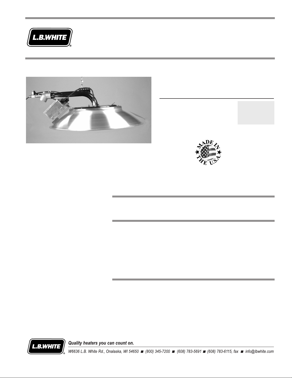
Spark Ignition Infraconic
Agricultural Building Radiant Heaters
MODELS OUTPUT (Btuh) FUEL
I34 34,200
Propane Vapor
Withdrawal
or Natural Gas
Congratulations!
You have purchased the finest radiant heater available for the heating of livestock
in agricultural animal confinement buildings.
Your new L.B. White radiant heater incorporates the benefits from the most
experienced manufacturer of heating products using state-of-the-art technology.
We, at L.B. White, thank you for your confidence in our products and welcome any
suggestions or comments you may have...call us toll free at 1-800-345-7200.
ATTENTION ALL USERS
This heater has been tested and evaluated by L.B. White Co., Inc. as a direct
gas-fired radiant heater with intended use for the heating of livestock in agricultural
animal confinement buildings. If you are considering using this product for any
application other than its intended use, then please contact your fuel gas supplier,
or the L.B. White Co., Inc.
150-23922-A
Page 2

Page 3
GENERAL HAZARD WARNING
■ Failure to comply with the precautions and instructions provided with this heater, can result in:
— Death
— Serious bodily injury or burns
— Property damage or loss from fire or explosion
— Asphyxiation due to lack of adequate air supply or carbon monoxide poisoning
— Electrical shock
■ Read this Owner’s Manual before installing or using this heater.
■ Only properly-trained service people should repair or install this heater.
■ Save this Owner’s Manual for future use and reference.
■ Owner’s Manuals and replacement labels are available at no charge. For assistance, contact
L.B. White at 1-800-345-7200.
WARNING
■ Proper gas supply pressure must be provided to the inlet of the heater.
■ Refer to rating plate for proper gas supply pressure.
■ Gas pressure in excess of the maximum inlet pressure specified at the heater inlet can cause
fires or explosions.
■ Fires or explosions can lead to serious injury, death, building damage or loss of livestock.
■ Gas pressure below the minimum inlet pressure specified at the heater inlet may cause
improper combustion.
■ Improper combustion can lead to asphyxiation or carbon monoxide poisoning and therefore
serious injury or death to humans and livestock.
WARNING
Fire and Explosion Hazard
■ Not for home or recreational vehicle use.
■ Installation of this heater in a home or
Fire and Explosion Hazard
■ Keep solid combustibles a safe distance
away from the heater.
WARNING
recreational vehicle may result in a fire or
explosion.
■ Fire or explosions can cause property
■ Solid combustibles include wood or paper
products, feathers, straw, and dust.
damage or loss of life.
■ Do not use the heater in spaces which
FOR YOUR SAFETY
Do not store or use gasoline or other
flammable vapors and liquids in the vicinity of
this or any other heater.
contain or may contain volatile or airborne
combustibles.
■ Volatile or airborne combustibles include
gasoline, solvents, paint thinner, dust
particles or unknown chemicals.
FOR YOUR SAFETY
If you smell gas:
1. Open windows.
2. Don't touch electrical switches.
3. Extinguish any open flame.
■ Failure to follow these instructions may
result in a fire or explosion.
■ Fire or explosions can lead to property
damage, personal injury or loss of life.
4. Immediately call your gas supplier.
22
Page 4

Table of Contents
SECTION PAGE
General Information . . . . . . . . . . . . . . . . . . . . . . . . . . . . . . . . . . . . . . . . . . . . . . . . . . . . . . . . . . . . . . . . . . .3
Heater Specifications . . . . . . . . . . . . . . . . . . . . . . . . . . . . . . . . . . . . . . . . . . . . . . . . . . . . . . . . . . . . . . . . . .4
Safety Precautions . . . . . . . . . . . . . . . . . . . . . . . . . . . . . . . . . . . . . . . . . . . . . . . . . . . . . . . . . . . . . . . . . . . .5
Installation Instructions
General . . . . . . . . . . . . . . . . . . . . . . . . . . . . . . . . . . . . . . . . . . . . . . . . . . . . . . . . . . . . . . . . . . . . . . . . .7
Gas Train Assembly . . . . . . . . . . . . . . . . . . . . . . . . . . . . . . . . . . . . . . . . . . . . . . . . . . . . . . . . . . . . . . . .9
Zone Control Panel Function and Installation . . . . . . . . . . . . . . . . . . . . . . . . . . . . . . . . . . . . . . . . . .10
Installing Dust Filter . . . . . . . . . . . . . . . . . . . . . . . . . . . . . . . . . . . . . . . . . . . . . . . . . . . . . . . . . . . . . .10
Start-Up Instructions . . . . . . . . . . . . . . . . . . . . . . . . . . . . . . . . . . . . . . . . . . . . . . . . . . . . . . . . . . . . . . . . .11
Shut-Down Instructions . . . . . . . . . . . . . . . . . . . . . . . . . . . . . . . . . . . . . . . . . . . . . . . . . . . . . . . . . . . . . . .11
Cleaning Instructions
A. Heater . . . . . . . . . . . . . . . . . . . . . . . . . . . . . . . . . . . . . . . . . . . . . . . . . . . . . . . . . . . . . . . . . . .12
B. Filter . . . . . . . . . . . . . . . . . . . . . . . . . . . . . . . . . . . . . . . . . . . . . . . . . . . . . . . . . . . . . . . . . . . .12
Maintenance Instructions . . . . . . . . . . . . . . . . . . . . . . . . . . . . . . . . . . . . . . . . . . . . . . . . . . . . . . . . . . . . .13
Service Instructions
General . . . . . . . . . . . . . . . . . . . . . . . . . . . . . . . . . . . . . . . . . . . . . . . . . . . . . . . . . . . . . . . . . . . . . . . .13
On/Off Switch . . . . . . . . . . . . . . . . . . . . . . . . . . . . . . . . . . . . . . . . . . . . . . . . . . . . . . . . . . . . . . . . . . .14
Ignition Module . . . . . . . . . . . . . . . . . . . . . . . . . . . . . . . . . . . . . . . . . . . . . . . . . . . . . . . . . . . . . . . . . .14
Burner Orifice . . . . . . . . . . . . . . . . . . . . . . . . . . . . . . . . . . . . . . . . . . . . . . . . . . . . . . . . . . . . . . . . . . .14
High Voltage Ignition Lead . . . . . . . . . . . . . . . . . . . . . . . . . . . . . . . . . . . . . . . . . . . . . . . . . . . . . . . . .15
Igniter . . . . . . . . . . . . . . . . . . . . . . . . . . . . . . . . . . . . . . . . . . . . . . . . . . . . . . . . . . . . . . . . . . . . . . . . . .15
High Limit Switch . . . . . . . . . . . . . . . . . . . . . . . . . . . . . . . . . . . . . . . . . . . . . . . . . . . . . . . . . . . . . . . .16
Gas Control Valve . . . . . . . . . . . . . . . . . . . . . . . . . . . . . . . . . . . . . . . . . . . . . . . . . . . . . . . . . . . . . . . .17
Gas Pressure Checks . . . . . . . . . . . . . . . . . . . . . . . . . . . . . . . . . . . . . . . . . . . . . . . . . . . . . . . . . . . . .17
Troubleshooting Guide . . . . . . . . . . . . . . . . . . . . . . . . . . . . . . . . . . . . . . . . . . . . . . . . . . . . . . . . . . . . . . . .18
Electrical Connection and Ladder Diagram . . . . . . . . . . . . . . . . . . . . . . . . . . . . . . . . . . . . . . . . . . . . . . .21
Heater Component Function . . . . . . . . . . . . . . . . . . . . . . . . . . . . . . . . . . . . . . . . . . . . . . . . . . . . . . . . . . .22
Parts Identification
Parts Schematic . . . . . . . . . . . . . . . . . . . . . . . . . . . . . . . . . . . . . . . . . . . . . . . . . . . . . . . . . . . . . . . . .23
Parts List . . . . . . . . . . . . . . . . . . . . . . . . . . . . . . . . . . . . . . . . . . . . . . . . . . . . . . . . . . . . . . . . . . . . . . .24
Warranty Policy . . . . . . . . . . . . . . . . . . . . . . . . . . . . . . . . . . . . . . . . . . . . . . . . . . . . . . . . . . . . . . . . . . . . .25
Replacement Parts and Service . . . . . . . . . . . . . . . . . . . . . . . . . . . . . . . . . . . . . . . . . . . . . . . . . . . . . . . .25
General Information
This owner's manual includes all options and accessories
commonly used on or with this heater. However, depending
on the configuration purchased, some options and
accessories may not be included.
When calling for technical service assistance, or for other
specific information, always have the model number and
serial number available.
This manual will instruct you in the operation and care of
your radiant heater. Have your qualified installer review this
manual with you so that you fully understand the heater and
how it functions.
33
The gas supply line installation, and the repair, installation
and servicing of the heater requires continuing expert
training and knowledge of gas heaters and should not be
attempted by anyone who is not so qualified. See page 6
for definition of the necessary qualifications.
Contact your local L. B. White distributor or the L. B. White
Co., Inc. for assistance, or if you have any questions about
the use of the heater or its application.
The L. B. White Co., Inc. has a policy of continuous product
improvement. It reserves the right to change specifications
and design without notice.
Page 5
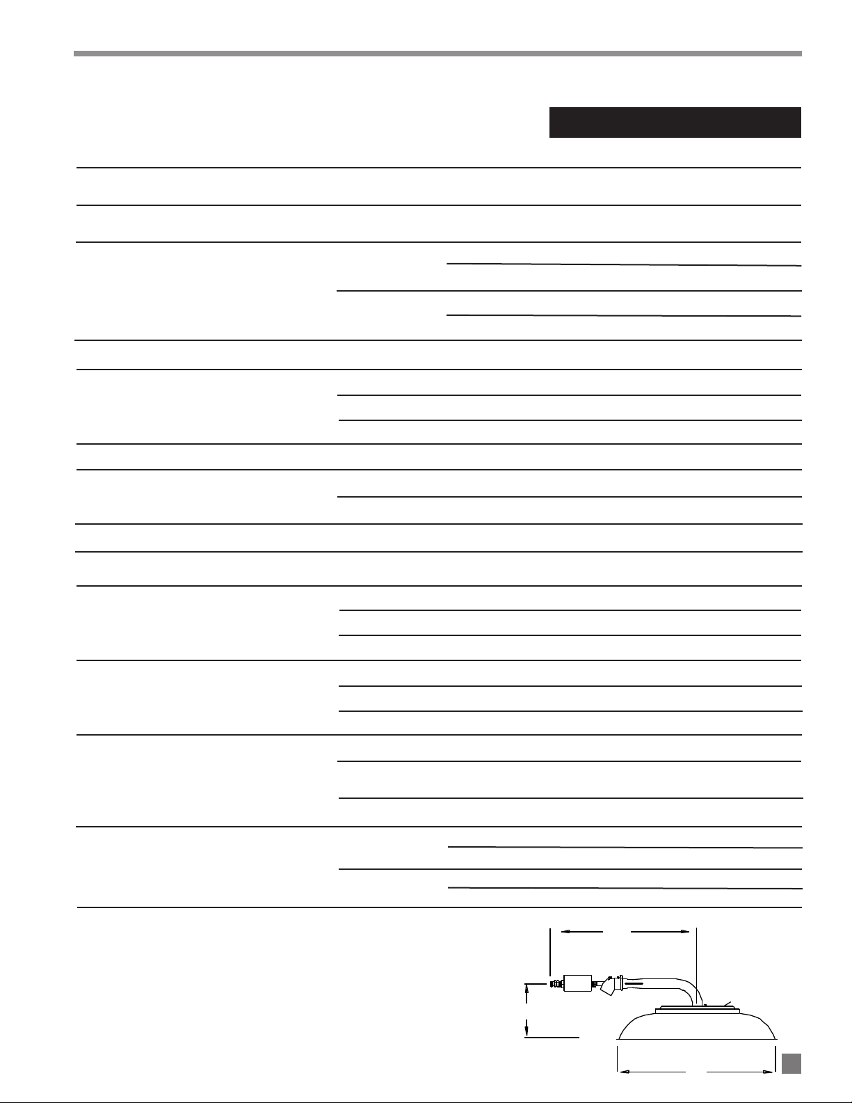
Radiant Heater Specifications
"B"
"A"
"C"
MMooddeell
SSPPEECCIIFFIICCAATTIIOONNSS
I34
Maximum Input (Btuh) 34,200
Ventilation Air to Support Combustion
FULL OUTPUT
Inlet Gas Supply Pressure at the Heater
(On/Off
Version)
ZONE
CONTROLLED
(Dual Solenoid
Version)
Burner Manifold Pressure at Maximum Pressure
MAX.
MIN.
MAX.
MIN.
400 CFM
5 psig
5 psig
5 psig
2.0 psig
5 psig
“A” 26-3/8 in.
Heater Dimensions
(See Fig. 1)
“B” 20 1/4 in.
“C” 10 3/8 in.
Net Weight 15 lbs. 8 oz.
Fuel Consumption Per Hour
Electrical Supply (Volts/HZ/Phase)
PROPANE GAS 1.58 lbs./hr.
NATURAL GAS
34.2 CFH
120/60/1
Amp Draw
CHICKENS 2500 - 3800
Animal Coverage Per Heater (1)
TURKEYS 800 - 950
SWINE 300
Recommended Height Installation
For Livestock From Point of
Combustion Cone to Floor
CHICKENS 6 - 7 ft.
TURKEYS 4.5 ft.
SWINE 4 - 5 ft.
TOP OF HOOD TO CEILING 3 ft.
Minimum Safe Clearances to
Combustible Materials
POINT OF COMBUSTION
CONE TO FLOOR
SIDES 3 ft.
Animal Occupied Zone Temperature
POULTRY
Control Sensor Location (2)
SWINE
(1) There are other factors that will affect the quantity of animals
(2) This is typical sensor placement range. The size and type of
each heater can cover. These include building ventilation and
control systems, building insulation, building size and population
density, etc. Consult your L. B. White dealer or call L. B. White for
specific recommendations for your application.
livestock being grown, heater spacing and height, etc. will dictate
sensor location. Care should always be taken to ensure that the
sensor is sufficiently high as to not be damaged by the animal
during operation.
0.5
4.5 ft.
VERTICAL FROM FLOOR 6-12 in.
HORIZONTAL FROM BROODER 8-12 ft.
VERTICAL FROM FLOOR Above Animal Height
HORIZONTAL FROM BROODER 4-8 ft.
FIG. 1
44
Page 6
Safety Precautions
Asphyxiation Hazard
■ Do not use this radiant heater for heating human living
quarters.
WWAARRNNIINNGG
L.B. White Company to determine combustion air
ventilation requirements of the heater.
■ Do not use in unventilated areas.
■ The flow of combustion and ventilation air must not be
obstructed.
■ Proper ventilation air must be provided to support the
combustion air requirements of the heater being used.
■ Refer to the spe c ification s ection of the Owner’s
Man u al , hea t e r’ s dat a pla te, or c on t ac t t he
■ Lack of proper ventilation air will lead to improper
combustion.
■ Improper combustion can lead to carbon monoxide
poisoning in humans leading to serious injury or death.
Symptoms of carbon monoxide poisoning can include
headaches, dizziness and difficulty in breathing.
■ Symptoms of improper combustion affecting livestock
can be disease, lower feed conversion, or death.
FUEL GAS ODOR
PPrrooppaannee ggaass aanndd nnaattuurraall ggaass hhaavvee mmaann--mmaaddee ooddoorraannttss aaddddeedd ssppeecciiffiiccaallllyy ffoorr ddeetteeccttiioonn ooff ffuueell ggaass lleeaakkss..
IIff aa ggaass lleeaakk ooccccuurrss,, yyoouu sshhoouulldd bbee aabbllee ttoo ssmmeellll tthhee ffuueell ggaass..
TTHHAATT’’SS YYOOUURR SSIIGGNNAALL TTOO GGOO IINNTTOO IIMMMMEEDDIIAATTEE AACCTTIIOONN!!
■ Do not take any action that could ignite the fuel gas. Do
not operate any electrical switches. Do not pull any
power supply or extension cords. Do not light matches
or a ny ot h er so u rce of fl a me. Do not us e you r
telephone.
■ Get everyone out of the building and away from the area
immediately.
■ Close all propane gas tank or cylinder fuel supply
valves, or the main fuel supply valve located at the
meter if you use natural gas.
■ Propane gas is heavier than air and may settle in low
areas. When you have reason to suspect a propane
leak, keep out of all low areas.
■ Natural gas is lighter than air and can collect around
rafters or ceilings.
■ Use your neighbor’s phone and call your fuel gas
supplier and your fire department. Do not re-enter the
building or area.
■ Stay out of the building and away from the area until
declared safe by the firefighters and your fuel gas
supplier.
FFIINNAALLLLYY ,,
■
firefighters check for escaped gas. Have them air out
the building and area before you return. Properly
trained service people must repair the leak, check for
further leakages, and then relight the heater for you.
le t the fuel gas service person a n d the
ODOR FADING -- NO ODOR DETECTED
SSoommee ppeeooppllee ccaannnnoott ssmmeellll wweellll.. SSoommee ppeeooppllee ccaannnnoott
■
ssmmeellll tthhee ooddoorr ooff tthhee mmaann--mmaaddee cchheemmiiccaall aaddddeedd ttoo
pprrooppaannee oorr nnaattuurraall ggaass.. YYoouu mmuusstt ddeetteerrmmiinnee iiff yyoouu ccaann
ssmmeellll tthhee ooddoorraanntt iinn tthheessee ffuueell ggaasseess..
■ Learn to recognize the odor of propane gas and natural
gas. Local propane gas dealers and your local natural
gas supplier (utility) will be more than happy to give you
a “scratch and snif f” pamphlet. Use it to become
familiar with the fuel gas odor.
■ Smoking can decrease your ability to smell. Being
around an odor for a period of time can affect your
sensitivity to that particular odor. Odors present in
animal confinement buildings can mask fuel gas odor.
TThhee ooddoorraanntt iinn pprrooppaannee ggaass aanndd nnaattuurraall ggaass iiss ccoolloorrlleessss
■
aanndd tthhee iinntteennssiittyy ooff iittss ooddoorr ccaann ffaaddee uunnddeerr ssoommee
cciirrccuummssttaanncceess..
■ If there is an underground leak, the movement of gas
through the soil can filter the odorant.
■ Propane gas odor may differ in intensity at different
levels. Since propane gas is heavier than air, there may
be more odor at lower levels.
AAllwwaayyss bbee sseennssiittiivvee ttoo tthhee sslliigghhtteesstt ggaass ooddoorr..
■
continue to detect any gas odor, no matter how small,
treat it as a serious leak. Immediately go into action as
discussed previously.
ATTENTION -- CRITICAL POINTS TO REMEMBER!
■ Propane gas and natural gas have a distinctive odor.
Learn to recognize these odors. (Reference “Fuel Gas
Odor” and “Odor Fading” sections above.
■
If you have not been properly trained in repair and service
of propane gas and natural gas fueled heaters, then do
not attempt to light the heater, perform service or repairs,
or make any adjustments to the heater on a propane (LP)
gas or natural gas fuel system.
55
■ Even if you are not properly trained in the service and
repair of radiant heaters, ALWAYS be consciously aware
of the odors of propane gas and natural gas.
■ A periodic “snif f test” around the heater or at the
heater’s joints; i.e. hose, connections, etc., is a good
safety practice under any conditions. If you smell even
a small amou nt of gas, CONTACT YOUR FUEL G AS
SUPPLIER IMMEDIATELY. DO NOT WAIT!
If you
Page 7
Safety Precautions
1. Do not attempt to install, repair or service this heater
or the gas supply line unless you have continuing
expert training and knowledge of gas heaters.
Qualifications for ser vice and installation of this
equipment are as follows:
QUALIFICATIONS FOR
SERVICING AND INSTALLATION:
a. To be a qualified gas heater service person, you
must have been tra i n ed in gas- f i red heater
ser vi c in g , rep a ir a n d als o have su f f i ci e nt
experience to allow you to troubleshoot, replace
defective parts, and test heaters in order to get
them into a continuing safe and normal operation
conditio n . You must co m p l ete ly familia r i z e
yourself with each model heater by reading and
complying with the safety instructions, labels,
owner’s manual, etc. that is provided with each
heater.
b. To be a qualified gas installation person, you must
have sufficient training and experience to handle
all aspects of installing, repairing and altering gas
lines, including selecting and installing the proper
equipment, and selecting proper pipe size to be
used. This must be done in accordance with all
local, state and national codes as well as the
manufacturer’s requirements.
5. This heater is intended for the heating of livestock in
agricultural animal confinement buildings only. The
heater shall only be mounted inside the animal
confinement building. It shall not be used for outside
heating applications.
6. Do not locate fuel gas containers or fuel supply hoses
anywhere within the heating zone of the heater.
7. Do not block the air intake, burner venturi tube or
burner cone area. Doing so may cause improper
combustion or damage to the heater components,
leading to property damage or animal loss.
8. Do not move, handle, or service the heater while in
operation or connected to fuel supply.
9. The hose assembly must be inspected on a regular
basis. This should be done at least once a year, or
when the building is cleaned out. If it is evident there
is excessive abrasion or wear, or if the hose is cut, it
must be replaced prior to heater b eing put into
operation. The hose assembly shall be protected
from animals, building materials, and contact with
hot surfaces during use. The hose assembly shall be
that specified by the manufacturer. See parts list.
10. Ch e c k for ga s leaks and proper func t i o n u pon
installation, before building repopulation and when
relocating.
2. All installations or applications of L. B. White Co.,
Inc.’s radiant heater and associated zone control
panel should meet the requirements of local, state
and national L.P. gas and natural gas, electrical and
sa fety codes. Yo ur gas s upplier, l ocal lic ensed
electrician, local fire department and government
agencies can help you determine these requirements.
In the absen c e of loca l codes, co mply with the
following:
-- ANSI/NFPA 58, latest edition, Standard for
Storage and Handling of Liquefied Petroleum
Gas and/or
-- ANSI Z223.1/NFPA 54, National Fuel Gas
Code
-- ANSI/NFPA 70, National Electrical Code.
3. If at any time you notice something unusual about the
ope r at i on of you r h e ate r s u ch as ga s o dor,
overheating, flames other than in the combustion
cone area, etc., evacuate the area immediately and
ca l l you r f i re depar t m e n t and you r gas ser v i c e
agency. Get assurances from the fire department
that the area is free of gas before you attempt to
relight the heater.
4. The components on the heater that call for hand
operation should work with hand pressure only. If
more force is required, have a qualified gas heater
service agency replace the complete part. Do not
attempt to repair.
11. If the gas flow is interrupted and the burner flame is
extinguished, immediately shut off the gas. Do not
relight the heater until you are sure that all of the gas
that may have accumulated through the heater has
cleared away. Do not relight the heater until at least
five minutes have passed.
12. If the heater is to be relocated, make sure that all gas
connections are capped and the gas supply is shut
off. All connection points must be leak checked after
disconnection and after reconnection.
WWAARRNNIINNGG
BBuurrnn HHaazzaarrdd
■ The heater’s combustion cones and canopy are
extremely hot during operation and shortly after
shutting down.
■ Always be aware of your proximity to the heater and
avoid contact with its hot surfaces during or shortly
after operation.
■ Failure to follow this warning can result in burns
leading to severe personal injury.
13. The grower shall inspect the heater before building
repopulation. Such inspection should consist of, but
is not limited to, the following points of action:
66
Page 8
-- Ins u re p r ope r cle a ra n ce o f he a ter to nea r es t
combustible materials.
-- Check for general cleanliness. Clean if necessary.
-- Check for tightness of the gas hose connections.
14. A qualified service person shall inspect the heater
and its gas train at least on an annual basis. This
should consist of, but is not limited to, the following
points of action:
-- Leak check of all pipe joints and hose connections.
-- Thorough cleaning of the exterior of the heater, its
inlet ventur i , comb u s t i o n con e s and filter (if
applicable).
-- Thorough inspection of the heater’s component
parts for corrosion, stripped threads, etc. with
subsequent parts replacement as necessary.
-- Gas pressure checks.
-- Start-up and shut down of the heaters and zone
control panel to test for proper operation.
Installation Instructions
GENERAL
1. Read all safety precautions and follow L. B. White
recommendations when installing this heater. If
during the installation or relocating of the heater, you
suspect that a part is damaged or defective, call a
qualified service agency for repair or replacement.
2. On initial installation and before use, position the
heater properly regarding clearance to combustible
materials and ground clearance to protect the heater
from livestock. Refer to the specification table on
page 4 as well as Figure 2 for installation information
for proper hanging and clearances.
3. The h e ater m a y b e con n ecte d t o an ap p ro v e d
electrical supply and operated from off to full heat
outp u t by util i zing t h e bui l d ing’ s e nvironm e nt
controller. In this type of installation, 5 psig must be
plumbed directly to each radiant heater for proper
combustion.
4. For installations requiring two stage heating, a zone
control panel is available which, when interfaced with
the building’s environment controller, will provide
from half to full heat output. Refer to page 10 of this
manual for more information relative to the control
panel.
5. Position the gas hose outside of the hot zone directly
above the heater. Position the gas hose to avoid any
opportunity for contact with the hot canopy surface of
the heater. Refer to Fig. 2.
6. Insure that all accessories that ship with the heater
have been removed from inside of heater’s shipping
container and installed. This pertains to gas hose,
regulators, etc.
7. The heater’s gas regulator (with pressure relief valve)
should be installed outside of building. Typically any
regulators inside the buildings must be properly
vented to the outside. However, local, state and
national codes always apply to regulator installation.
15. Turn off the gas supply when the heater is not in use.
8. Any reg u l a tor mounted outside the building be
pro tec ted ag a i n st the weather, pa r ticula r l y i c e
fo rm a ti o n. Ic e fo rm a ti o n can le a d to
overpressurization of the regulator and subsequent
gas leaks. See codes covering proper protection.
9. Always use pipe joint compound that is resistant to
liquefied petroleum gas and natural gas.
10. Check all connections for gas leaks using approved
gas leak detectors. Gas leak testing is performed as
follows:
WWAARRNNIINNGG
FFiirree aanndd EExxpplloossiioonn HHaazzaarrdd
■ Do not use open flame (matches, torches, candles,
etc.) in checking for gas leaks.
■ Use only approved leak detectors.
■ Failure to follow this warning can lead to fires or
explosions.
■ Fires or explosions can lead to property damage, injury
or death.
-- Check all pipe connections, hose connections,
fittings and adapters upstream of the gas
control with approved gas leak detectors.
-- In the event a gas leak is detected, check the
co mponents involved for cle anliness a nd
proper application of pipe compound before
further tightening.
-- Furthermore tighten the gas connections as
necessary to stop the leak.
-- After all connections are checked and any
leaks are stopped, turn on the main burner.
-- Stand clear while the main burner ignites to
prevent injury caused from hidden leaks that
could cause flashback.
77
Page 9

INSTALLATION LAYOUT G
FOR SAFE CLEARANCES
I17 & I34 - 3 FT. MINIMUMG
BROODER TOP TO CEILING
POSITION THE GAS HOSE AND ELECTRICAL POWER CORDG
OUTSIDE OF THE HOT ZONE DIRECTLY ABOVE THE HEATER.G
POSITION THE GAS HOSE AND POWER CORD TO AVOID G
ANY OPPORTUNITY FOR CONTACT WITH THE HOT CANOPYG
SURFACE OF THE HEATER.
MINIMUM 3 FT. CLEARANCEG
TO COMBUSTIBLES
FLOOR
I17 - 3.5 FT. MINIMUMG
I34 - 4.5 FT. MINIMUMG
POINT OF COMBUSTION G
CONE TO FLOORG
G
HANG THE HEATER WITH THE G
CONTROL END 1 TO 5 DEGREES DOWN G
FROM HORIZONTAL (SEE BELOW)
CONTROL PANEL
GAS PIPING
-- With the main burner in operation, check all
THIS NOT THIS
CONTROL END
KEYRING
STEEL CABLE
HANGING
CONTROL END
OR CHAIN
BRACKET
OF HEATER
MUST BE 1 TO 5 DOWN
FROM HORIZONTAL
connections, hose connections, fittings and
joints as well as the gas control valve inlet and
outlet connections with approved gas leak
detectors.
-- If a leak is detected, check the components
involved for cleanliness in the thread areas and
proper application of pipe compound before
further tightening.
-- Tighten the gas connection as necessary to
stop the leak.
-- If necessary, replace the parts or components
involved if the leak cannot be stopped.
-- Ensure all gas leaks have been identified and
repaired before proceeding.
11. A qualified service agency must check for proper
operating ga s pressures upon insta llation of the
heaters.
12. It is extremely important to use the proper gas supply
line to assure prope r functioning of the heaters.
Typically, 1/2 in. ID black iron pipe is used to convey
the gas to the heaters. However, always consult your
fuel gas supplier, or the L. B. White Co., Inc. for proper
line sizing and installation.
13. Infraconic heaters require a regulated gas supply to
the gas inlet. Exceeding the gas inlet pressure rating
can r e sult in po o r per form a nce a n d unr e lia b le
ope r at i on . Refer t o pa g e 4 o f thi s ma n ual f o r
information on gas pressu res r elating to specific
models.
14. The heater is designed for either L.P. vapor withdrawal
or natural gas, depending on model number. Do not
use t h is h e ater i n a n LPG l i qui d w it h dr a w a l
system. Do not permit LPG in liquid form to enter the
heater at any time.
15. T h e c o rro s ive at m osp her e p r ese nt i n a nim a l
confinement buildings can cause component failure or
heater malfunction. The heater should be periodically
insp e c ted and c l eane d in acc o rd ance with t h e
Maintenance and Cleaning Instructions in this manual.
Make sure that livestock is protected by a back up
alarm system that limits high and low temperatures
and also activates appropriate alarms.
16. Take time to understand how to operate and maintain
the heater using the owner’s manual. Make sure you
know how to shut off the gas supply to the building
and to the in dividu al hea ters. Conta ct yo ur gas
supplier if you have any questions.
17. Any defects found in performing any of the service
procedures must be eliminated and defective parts
replaced immed iatel y. Retest t he hea ter b efor e
placing it back into service.
AATTTTEENNTTIIOONN
FIG. 2
■ Model I34 heaters use an
integral hanging bracket with
key ring for hanging the heater.
■ Attach only steel cable or chain
to the key ring. Do not use
combustible hanging materials
such as ropes, lines, etc.
■ The installer must make sure
that the heater is hung so
control end of heater is
positioned 1º to 5º down from
horizontal after gas supply
hose is attached.This allows
proper venting of heater and
eliminates potential heat
damage to optional dust filter.
■ Repositioning of factory
installed key ring into hanging
bracket may be required.
■ Refer to following illustrations.
3 FT. MINIMUM
BROODER TOP TO CEILING
4.5 FT. MINIMUM
POINT OF COMBUSTION
CONE TO FLOOR
88
Page 10

BUSHING
RIGID END G
OF HOSE
TO GASG
SUPPLY
VALVE, SHUT-OFF
CONNECT HOSE TO GASG
INLET, TIGHTEN SECURELY
STANDARD HOSE
GAS TRAIN ASSEMBLY
1/8 NPT FITTING KIT, PART #23406
AB
NUT
STEM
- ASSEMBLE FITTING
FITTING ASSEMBLY
CONTROL VALVEG
INLET
- ATTACH FITTING TO GAS INLETG
& TIGHTEN SECURELY.G
- CONNECT APPROVED GAS HOSE ASSEMBLYG
WITH APPROPRIATE CONNECTIONS TO 1/8 NPT G
FITTING.
A
B
C
HOSE & QUICK COUPLING KIT
COLLAR
MALE END
COUPLING
VALVEG
SHUT-OFF
TO
GA
S
G
SUP
PL
Y
BUSHING
NIPPLE
DUST CAP
- ASSEMBLE COUPLING KIT, PART #21335,G
& TIGHTEN COMPONENTS SECURELY.G
- CONNECT TO GAS SUPPLY.
- PULL BACK COUPLING COLLAR.G
- FIRMLY PUSH MALE HOSE ENDG
INTO COUPLINGG
- RELEASE COLLAR. ENSUREG
MALE HOSE END IS SECURELYG
LOCKED INTO COUPLING.
CONNECT HOSE TO GAS INLET G
& TIGHTEN SECURELY
This heater is supplied with one of the following gas train
assemblies. Refer to the appropriate illustrations.
FIG. 3
FIG. 4
FIG. 5
99
Page 11

INJECTOR BODY TABS
FILTER ADAPTER
PART #23931
BEADED CABLE TIE
DUST FILTER
PART #23953
ZONE CONTROL PANEL
FILTER SLEEVE
PART #20421
FUNCTION AND INSTALLATION
(Optional)
With proper (5 PSIG) gas pressure supplied, spark ignition
heaters will operate in the standard ON/OFF mode when
electrically connected to a building environment controller or
thermostat
If you require two stages of heat for greater temperature
control, a two stage solenoid operated zone panel must be
installed. This panel incorporates solenoids to control the
first and second stage heating levels as well as a pressure
regulator to set the firing rate of the first stage. Use of this
panel requi r e s a t w o s t age therm o s t at or a buildi n g
controller capable of controlling the heat in two stages.
When energized by a building controller or thermostat, the
zone panel’s first stage solenoid opens providing 2 PSIG,
controlled by the regulator on the zone control panel, to the
heater. This represents approximately half the heater’s full
output. If this level of heating does not satisfy the demand,
the building controller or thermostat will call for the second
stage of heating, full output, by energizing the second stage
solenoid. This provides 5 PSIG to the heater.
As the heat demand is satisfied, the building controller or
thermostat will reduce the firing rate by closing the second
stage solenoid and lastly the first stage solenoid if heat is no
longer needed.
Two stage zone panels are available in high or medium
capacity configurations and will control the following quantity
of heaters depending on fuel type.
Solenoid Zone Control System
Medium High
Model and Capacity Capacity
Heat Output Fuel Panel Panel
Quantity Quantity
I34 L. P. Gas 7 20
(34,200 BTUH) Natural Gas 4 20
All zone control pan els mus t have an adjustabl e high
pressure regulator installed upstream of the inlet of the
panel. This regulator may be purchased from PSI as an
optional accessory. The regulator must be capable of
handli n g a m aximum i n l et press u r e of 10 p si, whil e
supplying an outlet pressure of 5 psi nominal.
Separate installation instructions accompany each zone
panel.
IMPORTANT
This filter kit is designed to provide additional dust filtration
capability and capacity for Infraconic heaters when installed
in severely dusty environments.
1. Attach filter sleeve to injector body. The injector body
tabs fit into the slots on the sleeve. Rotate the sleeve
to lock it onto the injector body.
2. Position the filter onto the sleeve. Ensure all sleeve
holes are covered by the filter.
FIG. 6
INSTALLING DUST FILTER
3. Securely attach the filter to the sleeve using the
beaded cable tie.
4. Ensure filter does not sag or touch heater’s canopy.
FILTER SLEEVE
FILTER
1100
Page 12

Start-Up Instructions
ON/OFF SWITCH
ON
Follow steps 1-5 on initial start up after heater installation
by a qualified gas heater service person. For normal
startup, simply turn the building thermostat above room
temperature.
1. Connect the heater to an approved electrical supply
and building’s temperature control system.
2. Open all gas supply valves to the heater and check
for gas leaks at all connections using approved leak
detectors.
3. Energize the building’s temperature control system to
provide power to the heater.
4. Position the ON/OFF switch on the heater’s control
box to ON. See Fig. 7. The igniter will spark and
ignition will occur.
5. Set the building’s temperature control to desired
temperature.
■ It is normal for air to be trapped in the gas line on new
installations.
■ The heater may attempt more than one ignition trial
before air is purged from the line and ignition occurs.
purposes of controlling the timing of the ignition process of
the heater as well as monitoring the safety functions. The
control module is located in a control box at the gas inlet
end of the heater. On a call for heat, the igniter will spark
and the gas control valve will open shortly afterward. The
igniter will continue to spark for approximately 10 seconds.
Flame sense, as monitored by the ignition control, will keep
the gas valve open and main burner in operation until
proper temperature is achieved.
The ignition control module will make up to 3 trials for
ignition. There will be a 15 second time span between each
ignition trial. If ignition is not achieved after the third trial, a
15 minute wait period will occur. After the 15 minute time
span has elapsed, the heater will make three more trials for
ignition. This process will continue as long as there is a call
for heat from the building’s temperature control system.
FIG. 7
This heater includes a spark ignition control module for
Shut-Down Instructions
The building’s environmental temperature control system
will shut the heater down after proper temperature has been
achieved.
If heater is to be shut down for cleaning, maintenance or
service:
1. Shut off all gas supply valves to the heaters.
2. Allow heaters to burn off fuel gas remaining in the
gas supply line.
3. Position the ON/OFF switch to OFF.
4. Disconnect the heater from its electrical supply.
1111
Page 13

AIR NOZZLE
Cleaning Instructions
It is important to clean the heater and the optional dust
filter on a regular basis to maintain proper combustion and
to eliminate future problems.
wwaatteerr oorr ootthheerr lliiqquuiiddss..
The frequency of cleaning w i l l vary depen d i n g u p on
livestock being raised and overall ventilation of the building.
Problems associated with lack of cleaning typically are:
DDoo nnoott cclleeaann tthhee hheeaatteerr wwiitthh
■ Black soot on inside of canopy.
■ Gas backflashing in venturi tube or injector body.
■ Burner flame appearing beyond outer cone.
AA.. HHEEAATTEERR
CLEANING WITH BACKPACK BLOWERS
AND HEATER BLOWER
Blower Part No. 21170
For general cleaning when the heaters do not have heavy
accumulations of dust or dirt, use either a backpack type of
blower or the heater blower.
Foll ow the same procedures for cleaning as listed for
“Cleaning with Compressed Air”.
If the dust and dirt cannot be removed effectively using the
backpack blower or heater blower, then clean the heater
using the Compressed Air cleaning method which follows.
CLEANING WITH COMPRESSED AIR
5. Inspect the cones and venturi tube to make sure
these areas are clean.
6. Return the heater to its normal hanging position and
relight the heater.
FIG. 8
BB.. FFIILLTTEERR
11.. DDuurriinngg CCoonnttiinnuueedd HHeeaatteerr UUssee
- Remove filter and shake off dust.
- Do not squeeze or tap filter while filter is installed on
heater. Doing so will allow dust to be blown into venturi
tube or combustion cones.
22.. AA ff tt eerr CC oonntt iinnuu eedd HHee aatt ee rr UUssee oorr BB eeff oorr ee BBuu ii llddiinngg
RReeppooppuullaattiioonn
1. Turn off the gas supply to the heater and let the
heater cool down.
2. Direct the air at the combustion cones, working your
way around entire surface of cone assembly.
See Fig. 8.
3. Blow air through air inlet opening in the injector body
to bl ow bac k ou t an y lo o se n ed dus t th roug h
combustion cones.
4. Repeat Steps 2 and 3 until the cones and the venturi
tube are no longer emitting dust.
- Remove filter and shake off dust.
- Use compressed air or standard water faucet pressure
to clean it.
- Do not use high pressure water, air, or a washing
machine as filter material damage may occur.
- If water is used, squeeze out excess water from filter
before installation.
- Let filter dry before lighting heater.
1122
Page 14

Maintenance Instructions
1. Have your gas supplier check all gas piping annually
for leaks or restrictions in gas lines. Also, at this time
have your gas supplier clean out the sediment trap on
the zone control panel of any debris that may have
accumulated.
TThhee hheeaatteerr’’ss ssuurrrroouunnddiinngg aarreeaa sshhaallll bbee kkeepptt cclleeaarr aanndd
2.
ffrreeee ffrroomm ccoommbbuussttiibbllee mmaatteerriiaallss,, ggaassoolliinnee,, aanndd ootthheerr
ffllaammmmaabbllee vvaappoorrss aanndd lliiqquuiiddss..
3. Regulators can wear out and function improperly.
Have your gas supplier check the date codes on all
regulators installed and check delivery pressures to
the appliance to make sure that the regulator is
suitable for continued use.
4. Regulators must be periodically inspected to make
sure the regulator vents are not blocked. Debris,
insects, insect nests, snow, or ice on a regulator can
block vents an d cause excess pre s s ure at the
appliance.
5. For safety as well as for optimum performance at the
heater, it is necessary to keep the inside and the
outsi d e of the h e ater fre e o f dust , d ir t o r any
combustible material. If any operational component
show s si g ns o f ru s t or c or r o si o n, r e pl a ce t he
component immediately.
6. If any warning or instruction labels, dataplates, etc.
bec o me l o st o r h ard to r ead , r ep l ac e t hem
immediately. Do not operate the heater until you
have all instructions and can read and understand
them.
7. Check overall condition of heater for cracked or
damaged components, loose screws or bolts, etc.
Replace any suspect components.
8. Check all hose and tubing assemblies for cracks,
abrasions or ruptures. Replace any hoses that are
suspect.
If it becomes apparent that a dark spot has formed part way
up on the inner combustion cone or a build up of debris is
occurring in the bottom of the in n e r c o ne, it will be
necessary to clean out the combustion cone assembly.
Refer to “Cleaning Instructions”.
Service Instructions
GENERAL
WWAARRNNIINNGG
BBuurrnn HHaazzaarrdd
■ Heater surfaces are extrememly hot for a period of
time after the heater has been shut down.
■ Allow the heater to cool before performing service,
maintenance, or cleaning.
■ Failure to follow this warning will result in burns
causing injury.
WWAARRNNIINNGG
FFiirree aanndd EExxpplloossiioonn HHaazzaarrdd
■ Do not disassemble or attempt to repair any heater
components or gas train components.
■ All component parts must be replaced if defects are
found.
■ Failure to follow this warning will result in fire or
explosions, causing property damage, injury, or death.
1. Clo s e th e fu e l su p pl y val v e to th e he a ter a n d
disconnect the hea ter’ s elec trical supp ly before
servicing unless it is necessary to have the valve open
and electrical supply connected for your service
procedure.
2. In servicing some components, it may be necessary to
remove optional filter kit.
3. Remove the control box cover for access to ignition
control,high limit switch, and on/off switch.
4. Fo r r eassembly, r eve r s e t he respective ser vice
procedure. Ensure gas connections are tightened
securely.
5. Af ter servicing, star t the heater to ensure proper
operation and check for gas leaks.
CClleeaann tthhee hheeaatteerr’’ss oorriiffiicceess wwiitthh ccoommpprreesssseedd aaiirr oorr aa
6.
ssoofftt,, ddrryy rraagg.. DDoo nnoott uussee ffiilleess,, ddrriillllss,, bbrrooaacchheess,, eettcc.. ttoo
cclleeaann tthhee oorriiffiiccee hhoolleess.. DDooiinngg ssoo wwiillll eennllaarrggee tthhee hhoollee,,
ccaauussiinngg ccoommbbuussttiioonn oorr iiggnniittiioonn pprroobblleemmss.. RReeppllaaccee tthhee
oorriiffiiccee iiff iitt ccaannnnoott bbee cclleeaanneedd pprrooppeerrllyy..
1133
Page 15

IGNITION LEAD
IGNITION CONTROLG
MOUNTING SCREWS
ADAPTER
INLET
BUSHING
GROUND LEAD
VALVE GROUNDING ANDG
ATTACHMENT SCREW
G
ADAPTER
VENTURI G
NECK
BURNER ORIFICE
GAS CONTROLG
VALVE
BOOT
SWITCH
ON/OFF SWITCH
1. Disconnect the electrical leads from the ON/OFF
switch.
2. Remove the rubber boot from the ON/OFF switch.
See Fig. 9. Remove the switch from the control box.
■ Handle the module at the edges of the board
■ Do not touch or allow any contact to the module
components, otherwise damage may occur.
1. Disconne ct all elect rical leads from th e igni tion
control terminals.
FIG. 9
IGNITION MODULE
FIG. 10
2. Disconnect high voltage ignition lead.
3. Remove ignition control module mounting screws.
See Fig. 10.
1. Remove valve grounding and attachment screw.
2. Remove injector body with gas control from venturi
tube.
3. Using a 6 mm hex nut driver, remove the orifice.
4. Clean the orifice hole. Reinstall orifice into the orifice
body. Do not overtighten the orifice as overtightening
can strip the threads in the injector body.
BURNER ORIFICE
FIG. 11
INJECTOR
BODY
1144
Page 16

NUTS
SCREWS
IGNITOR W/ BRACKET
DISCONNECT FROM
IGNITOR LEAD
LOOSEN NUT
B
A
C
HIGH VOLTAGE IGNITION LEAD
GAPPING TOOL
.100
.125
.175
.100
.125
.175
1. Disconnect the igniter lead from ignition module.
2. Loosen the water tight connector nut. See Fig. 12.
Pull the ignition lead through this connection.
3. Disconnect the high voltage ignition lead from the
ignitor. See Fig. 12.
4. Remove the connector nut from the ignition cable.
This nut will be used on the replacement ignition
cable.
5. Although the ignition lead is self locating, ensure it is
positioned away from the venturi tube and the lead
boot is covering the ignitor terminal.
IGNITER
1 Disconnect the ignition lead from the ignitor. Remove
ignitor mounting screws. See Fig. 13.
Fig. 13
FIG. 12
LOOSEN WATER
TIGHT NUT
DISCONNECT
LEAD FROM
IGNITION
CONTROL
FIG. 14a
DISCONNECT
LEAD FROM
IGNITOR
TERMINAL
IGNITOR
TERMINAL
2. Remove the igniter from the heater. Clean the rod with
steel wool or emery cloth.
3. The rod and its insulating ceramic body must be rigid
within its mounting flange. If the rod or its body are
capable of movement, the igniter will not be properly
positioned to the combustion cone. The igniter must
then be replaced.
AAddjjuussttiinngg IIggnniittoorr GGaapp
Ignitor gap may need to be adjusted if spark is still weak
or non-existent after the ignitor has been either cleaned
or replaced. Refer to the following instructions.
a. Ensure the three burner plate nuts are securely
tightened. See Fig 14a.
1155
b. Use gapping tool, part # 23967, to set the gap to .175
inches. See Fig.14b.
FIG. 14b
GAPPING TOOL
c. Insert tool at opening between inner and outer
combustion cone tips.
Page 17

TERMINAL
MOUNTING LEG
RESET BUTTON
SENSING SURFACE
FLAME
d. Position the tool between inner cone and ignitor
INNER
CONE
T
OOL
.175 GAP BETWEEN
ELECTRODE AND CONE
tip. See Fig. 14c.
FIG. 14c
e. If the gap exceeds the minimum to maximum
tolerances of the tool, reset the gap:
-- loosen igniter mounting screws.
-- reposition the igniter assembly until the
gap is within the proper tolerances.
f. Tighten the igniter mounting screws.
■ This heater is equipped with a manual reset high limit
switch. Its purpose is to disconnect the electrical
supply to the ignition control board in the event of an
overheat condition.
■ An overheat condition is normally caused by:
-- Excessive fuel gas pressure.
-- Heater not being routinely cleaned.
-- Heater not properly hung. (See page 8.)
The high limit switch should be tested a minimum of once
a year or anytime the heater is taken down for servicing.
Refer to the following testing instructions.
WWAARRNNIINNGG
FFiirree HHaazzaarrdd
■ Do not operate the heater with the high limit switch
bypassed.
■ Operating the heater with a bypassed high limit switch
may lead to overheating, possibly resulting in a fire,
with subsequent damage to the heater and building,
or loss of livestock.
HIGH LIMIT SWITCH
2. Apply a small flame only to the sensing portion on the
back of the switch.
hhoouussiinngg ooff tthhee sswwiittcchh wwhheenn ccoonndduuccttiinngg tthhiiss tteesstt..
4. Within a minute, you should hear a pop coming from
the switch, indicating the contacts of the switch have
opened.
5. Allow the switch cool down before firmly pressing the
reset button.
6. Check for electrical continuity across the switch
terminals.
7. Reinstall the switch back into the heater.
FIG. 15
BBee ccaarreeffuull nnoott ttoo mmeelltt tthhee ppllaassttiicc
1. Remove the high limit switch from the control box.
1166
Page 18

FUEL SUPPLY VALVEG
(OPEN THIS VALVE TO USEG
PRESSURE GAUGE)
G
TEST KIT HOSE
PRESSURE GAUGE KITG
20736
GAS SUPPLY HOSE
GAS CONTROL VALVE
OPEN
G
ADAPTER
INLET
BUSHING
GROUND LEAD
VALVE GROUNDING ANDG
ATTACHMENT SCREW
INJECTOR G
BODY
ADAPTER
GAS CONTROL G
VALVE
GAS CONTROL VALVE
1. Brush or blow off any dust in vicinity of gas control
valve.
2. Disconnect the gas hose and remove control box
cover.
3. Loosen water tight connector nut at the control box
for the power supply leads of the control valve.
4. Disconnect the valve’s electrical leads from the
ignition module.
5. Remove the connector nut from the valve leads.
6. Loosen the valve ground and attachment screw at the
injector body.
GAS PRESSURE CHECKS
AA.. PPrreeppaarraattiioonn
1. Obtain an L.B. White pressure gauge test kit -
Part # 20736.
2. Disconnect the heater from the electrical supply and
close the fuel supply valve to the heater.
3. Brush or blow off any dust and dirt on or in the vicinity
of the gas control valve.
4. Disconnect the gas hose from the heater.
BB.. GGaauuggee IInnssttaallllaattiioonn
1. Connect the pressure test kit between the heater and
gas supply hose. See Fig. 17. Insure both gas shutoff valves on the test kit are in the closed position
when connecting the kit to the heater and gas supply.
2. Reconnect the heater to its electrical supply and open
the main fuel supply valve to the heater.
7. Remove bushing with hose adapter from control valve
inlet. See Fig. 16.
8. Secure the gas valve adapter at the outlet of the gas
control. Remove the control valve from adapter.
FIG. 16
CC.. RReeaaddiinngg PPrreessssuurreess
1. With the heater operating, the pressure gauge should
read the pressure specified on the dataplate.
2. Does the reading on the gauge of the test kit agree
with that specified on the dataplate? If so, then no
further checking or adjustment is required. Proceed
to Section D.
3. If the pressure does not agree with that specified on
the dataplate, then the regulator controlling gas
pressure to the heaters requires adjustment.
DD.. CCoommpplleettiioonn
1. On c e gas pressu r e has been c o nf irmed and/or
properly set, close the fuel supply valve to the heater
and allow the heater to burn off any gas remaining in
the gas supply hose.
2. Disconnect the heater from its electrical supply.
3. Open only the gas shut-off on the test kit which is
4. Light the heater.
FIG. 17
1177
connected to gas supply.
3. Remove the gauge kit and reconnect the gas hose
and electrical supply to the heater. Tighten securely.
4. Ope n t h e f u el su p pl y va l ves an d se t bu i ld i ng
controller to desired temperature.
Page 19

Troubleshooting Guide
READ THIS ENTIRE SECTION BEFORE
BEGINNING TO TROUBLESHOOT PROBLEMS.
The following troubleshooting flow charts provide systematic
procedures for isolating heater problems. The charts are
intended for use by a QUALIFIED GAS HEATER SERVICE
PERSON.
BBEEEENN PPRROOPPEERRLLYY TTRRAAIINNEEDD..
TEST EQUIPMENT REQUIRED
The following pieces of test equipment will be required to
troubleshoot this system with minimal time and effort.
•• DDiiggiittaall MMuullttiimmeetteerr
•• PPrreessssuurree GGaauuggee
pressures to the heaters.
IINNIITTIIAALL PPRREEPPAARRAATTIIOONN
-- Inspect the heater for damage.
-- Clean the heater as necessary.
DDOO NNOOTT SSEERRVVIICCEE TTHHEE HHEEAATTEERR UUNNLLEESSSS YYOOUU HHAAVVEE
- For measuring voltage.
- (Part No. 20736) For checking inlet
WWAARRNNIINNGG
EElleeccttrriiccaall SShhoocckk aanndd BBuurrnn HHaazzaarrdd
■ Troubleshooting this system may require operating the
heater with the burner on. Use extreme caution when
working on the heater.
■ Failure to follow this warning may result in electrical
shock or burns causing severe injury.
HHeeaatteerr PPrroobblleemmss PPaaggee
1.Heater does not light................................................19
2.Heater lights, but will not stay lit ............................20
3.Heater backflashes gas through air inlet. ..............20
Components should be replaced only after each step has
been completed and replacement is suggested in the flow
chart. Refer to the “Servicing” sections as necessary to
ob t a i n information on d i s a ssembly and replace m e n t
procedures of the component once the problem is identified
by the flow chart.
OPERATION SEQUENCE:
••
A call for heat occurs from building thermostat.
••
Line voltage is sent from building’s temperature control
to heater’s ON/OFF switch.
••
Switch sends power to ignition control through high
limit switch.
-- Ignition control module begins ignition trial sequence
-- Ignition control sends high voltage to igniter
electrode
-- Igniter sparks
-- Gas control solenoid opens
••
Ignition occurs
-- Igniter continues to spark for 10 seconds until
flame proving occurs
-- Ignition spark is shut off
-- Gas control solenoid stays open
••
Ground warms to desired temperature
-- Building thermostat is satisfied
-- Heater shuts down
••
Process is repeated on a call for heat
IGNITION FAILURE SEQUENCE:
••
Ignition control will make three ignition trials
-- Each trial lasts 10 seconds
-- 15 seconds time span between each trial
••
If ignition control does not establish flame sense within
ignition trial:
-- Ignition spark shuts off
-- Gas valve closes
••
After three ignition trials, ignition control will wait for 15
minutes before retrying for ignition.
••
This process will be repeated continually until the
ignition problem is solved.
••
To manually reset the ignition control:
-- Unplug the heater and plug it back in
OR
-- Turn the building temperature control to off and
then back on.
OR
-- Turn ON/OFF switch on heater off. Wait 5
seconds, then turn back on.
1188
Page 20

Yes
Inner
Combustion
Cone , Venturi
Tube or Main
Burner Orifice
are Plugged with
Dirt. Clean the
Heater.
No
to ON?
Is ON/OFF Switch
on Heater Positioned
Position the
Switch to ON.
Yes
Yes
Is an
Audible Click
Valve is Supplied
Heard When Solenoid
No
Is Proper
Switch?
Voltage Being
Cord to On/Off
Sent through Power
Resistance.
Power Cord for
Check Leads of
Replace Power
Cord if Necessary.
Yes
Yes
Is Proper
Gas Control Valve
Voltage Supplied to
Is
Heater Power
Proper Voltage
Supplied to Zone
Control Panel and
No
Cord?
Yes
environment control
thermostat is working
properly and calling for
- Check Circuit Breakers
- Make sure building
Provide Proper Voltage.
heat
Yes
No
Is Proper
To Heater?
Gas Pressure
Supplied to Zone
Control Panel and
Pressure.
Provide Proper
Does Igniter Spark?
Yes
No
Voltage?
Valve
Replace Gas Solenoid
No
on Heater?
Control.
Replace Ignition
No
Defects, Cleanliness, and
Proper Gap.
A. Check Igniter for
Connections and No Cuts
Verify Resistance of Lead.
Replace if Necessary.
are Good, Replace
Ignition Control.
B. Check Ignition Lead.
C. If Igniter and Ignition Lead
1199
Yes
Is High
Voltage to Ignition
Limit Switch Sending
No
Valves Open?
Are All Fuel Supply
Open All Fuel Supply Valves
PPrroobblleemm 11
HHeeaatteerr
DDooeess
NNoott LLiigghhtt
Yes
Is
Proper Voltage
being sent from
ON/OFF Switch to
No
Control?
Check for Tripped High
Limit Switch. Reset the
Tripping.
Determine Cause of
High Limit Switch and
No
Switch?
High Limit
Defective.
Check for Voltage
Leads Between
and Resistance of
Switch and Electrical
Control. Replace if
Switches and Ignition
Page 21

or Main Burner Orifice
are Plugged with Dirt.
Yes
Inner Combustion Cone
components.
Clean these
Yes
Is
Flame Sense
Connected and in
Ground Lead Properly
Yes
Is Heater’s
Reasonably
Venturi Tube
No
Good Condition?
Check the Lead for:
Resistance
- Corroded Terminal
- Loose Connections
- Continuity/
Repair or Replace as
Is Igniter Clean?
?
No
Clean
Necessary.
No
Clean its Electrode.
Remove Igniter and
Clean the Heater.
Yes
?
No
Clean
Dust Filter
Is Heater’s
Reasonably
the Filter.
Remove and Clean
Replace Combustion Cone.
Yes
Yes
21088
Part Number
Combustion Cone Kits
Clean these
Components.
Yes
Tighten the Nuts
Yes
Plate.or Gasket
Replace the Burner
Yes
Plate Notch.
Weld Seam in Burner
Position the Inner Cone
No
No
Is Proper
to the Heater?
Pressure Supplied
Supply Proper Pressure
and Check for Blockages
Necessary.
in Gas Hose. Refill
L.P. Gas Containers if
Is Inner
Cone Seam
Damaged or
Fractured or is Tip
No
Are
Missing?
Injector
Body, Burner
Tube, or Inner Cone
Orifice,Filter, Venturi
Partially Plugged with
No
Dirt?
Assembly
Are Burner
No
Nuts Loose?
Gasket
Is the Burner
Plate or Burner
No
Notch?
Aligned to
Cracked?
Weld Seam
Burner Plate
Is Inner Cone
Yes
Yes
No
Is High
Condition?
Lead in Good
Voltage Ignition
Verify Continuity Value of
HHeeaatteerr
LLiigghhttss bbuutt
wwiillll nnoott
PPrroobblleemm 22
SSttaayy LLiitt
Replace if Necessary.
Connections, and No Cuts.
Lead. Verify Lead has Good
Is Proper
Gas Pressure
Being Supplied to
PPrroobblleemm 33
HHeeaatteerr
No
the Heater?
Gas Pressure.
Check for Proper
BBaacckkffllaasshheess
GGaass TThhrroouugghh
AAiirr IInnlleett..
Read 5 PSIG.
High Heat Should
Proper Pressure at
2200
Page 22

Electrical Connection and Ladder Diagram
CAUTION: REFER TO THE HEATER'S ELECTRICAL CONNECTION
DIAGRAM WHEN SERVICING TO AVOID WIRING ERRORS AND HEATER
MALFUNCTION. CHECK FOR PROPER OPERATION AFTER SERVICING.
WARNING: THIS HEATER MAY START AT ANY TIME
HIGH VOLTAGE IGNITER LEAD
IGNITER
RED RED
GROUND
WHITE
RED
GREEN
BLACK
RED
GROUND
BLACK
BLACK
GREEN
WHITE
SPARK
IGNITION
CONTROL
NOTE: POWER CORD IS
CONNECTED TO
THERMOSTAT OR
BUILDING ENVIRONMENTAL
CONTROL SYSTEM
ELECTRICAL CONNECTION DIAGRAM
N2
N3
GND
L1
MV
ON/OFF
SWITCH
POWER
CORD
GAS
CONTROL
VALVE
GROUND
SPARK
IGNITION
CONTROL
ELECTRICAL LADDER DIAGRAM
N2
N3
GND
L1
MV
ON/OFF
SWITCH
L1
GROUND
IGNITER
SOLENOID
NEUTRAL
IF ANY OF THE ORIGINAL WIRE AS SUPPLIED WITH THE HEATER
MUST BE REPLACED, IT MUST BE REPLACED WITH WIRING MATERIAL
HAVING A TEMPERATURE RATING OF AT LEAST 302°F (150°C)
HIGH
LIMIT
SWITCH
HIGH LIMIT
SWITCH
150-22824-A
2211
Page 23

Heater Component Function
Burner Orifice
Metering device used to feed gas to combustion cones at a
specific flow rate.
Canopy
Reflective aluminum heat shield for heater.
Double Combustion Chamber
Made of special alloy steel. This is where combustion of gas
occurs, providing radiant heat used in the warming process.
Consists of small inner cone and large outer cone
Gas Control Valve
Component that houses electromagnet which is energized by
voltage and therefore opens or closes to supply or shut off
the flow of gas to the burner.
Gas Hose
Flexible connector used to convey gas from gas supply line
to inlet of heater.
High Limit Switch
Safety device wired into the heater’s electrical supply which
is used to open the electrical circuit to the ignition control
module in the event of an overheat condition.
Igniter/Sensor
Electrical ignition device used on automatic ignition control
systems. Ignites gas by spark. The igniter also serves as a
flame sensor on this heater to prove flame after ignition
Ignition Control Module
Electronic device which controls the ignition sequence and
operation of the heater.
Injector Body
Allows combustion air to be drawn in to injector tube with
gas flow for combustion.
Manual Shut Off Valve
It’s purpose is to shut off gas flow to the appliance if
maintenance or service are required, or if an emergency
situation occurs. When the handle on the manual valve is
turned parallel to gas flow, the valve is completely open
delivering full gas supply to the appliance. Turning handle
perpendicular (90°) to gas flow shuts off gas flow.
On/Off Switch
Simple electrical device used to connect or disconnect
incoming voltage at the ignition control box on the heater.
Venturi Tube
Tubular steel neck connecting the gas control valve and
burner orifices to the combustion cones. Gas is fed to the
combustion cones through the injector tube.
2222
Page 24

Parts Identification
2
4
35
34
36
37
33
32
30
27
26
25
29
28
31
14
17
18
39
8
10
4
13
11
40
3
6
9
16
20
19
2
7
21
1A
31A
31B
1B
42
38
41
23
PARTS SCHEMATIC
2233
Page 25

PARTS LIST
Item Description Part Number
1A Inner Cone 09557
1B Outer Cone 09556
Combustion Cone Kit with Gasket 21088
2 Gasket 09560
3 Plate, Burner 22212-04
4 Igniter Kit 24050
6 Spacer 09568
7 Screw 10-32 x 1 1/2 23636
8 Nut 10-32 09578
10 Key Ring 09620
13 Lead, Igniter w/ Boot 23989
14 Connector, Liquid Tight 08948
16 Control, Direct Spark Ignition 22715
17 Switch, On/Off 22714
18 Boot, On/Off Switch 09916
19 Bracket, Control Box 24047
20 Control Box Cover w/ Gasket 23986
21 Control Box Bottom 23985
22 Bushing 01544
23 Adapter, Hose 23789
24 Valve, Gas Control w/ Electrical Leads 23729
and Screen
25 Orifice, Burner Propane Gas 26702
Natural Gas 26701
26 Injector Body w/ Air Register Plate Propane Gas 20672
Natural Gas 21559
27 Retaining Screw for Injector Tube 09572
28 Adapter 1/8 NPT x 1/8 BSP 23707
29 Lead, Black, On/Off Switch to Ignition Control 22610
30 Hose, Gas 1/4 in. x 6 ft. Rigid x Swivel, Poultry 20495
1/4 in. x 10 ft. Rigid x Swivel, Poultry 20496
1/4 in. x 12 ft. Rigid x Swivel, Poultry 20497
1/4 in. x 6 ft. Swivel Both Ends, Swine 20499
1/4 in. x 10 ft. Swivel Both Ends, Swine 20242
1/4 in. x 15 ft. Swivel Both Ends, Swine 20500
31 Filter Kit 20428
31A Sleeve 20421
31B Filter 23953
32 Plug 20358
33 Cord, Power 22704
34 Screw, Igniter Mounting 06658
35 Tube, Injector 09597
36 Lock Nut 08948
37 Screw, Injector Body 09575
38 Screw, Direct Spark Ignition 02330
39 High Limit Switch, Manual Reset 23148
40 Screw, High Limit Switch 22783
41 Gasket, Liquid Tight 22565
42 Wire, High Limit Switch 22610
43 Quick Coupling Kit, Female Coupling and Shut-Off (Not Illustrated) 21335
Consisting Of:
Shut-Off Valve 05548
Nipple, 1/4 in. Close 01142
Coupling, Quick Disconnect 21328
Bushing, 1/2 x 1/4 01519
44 Kit,1/8 NPT Fitting ( Not Illustrated) 23406
2244
Page 26

Warranty Policy
EQUIPMENT
L.B. White Co., Inc. warrants that the component parts of its
equ i pme n t a r e fr e e fr o m de f e cts in ma teri a l a n d
workm anshi p, when properly ins talle d, operated, and
mainta i n ed in accorda n c e with th e I n s tallat i o n and
Maintena n c e I nstruc t i ons, safety g u i d es and lab e l s
contained with each unit. If,
ddaattee ooff ppuurrcchhaassee bbyy tthhee eenndd uusseerr
to be defective, L.B. White Co., Inc. will at its option, repair
or replace the defective part or equipment, with a new part
or equipment, F.O.B., Onalaska, Wisconsin.
wwiitthhiinn 1122 mmoonntthhss ffrroomm tthhee
, any component is found
PARTS
L. B . White Co. , Inc. war r a nts that r e placement pa r ts
purchased from the company and used on the appropriate
L. B. White equipment are free from defects both in material
and workmanship for
bbyy tthhee eenndd uusseerr
found defective within 12 months of the date code marked
on the part. If the defect occurs more than 12 months later
than the date code but within 12 months from the date of
purchase by the end user, a copy of a bill of sale will be
required to establish warranty qualification.
The warranty set for th above is the exclusive warranty
provided by L.B. White, and all other warranties, including
any implied warranties or merchantability or fitness for a
particular purpose, are expressly disclaimed. In the event
any implied warranty is not hereby effectively disclaimed
due to operation of law, such implied warranty is limited in
1122 mmoonntthhss ffrroomm tthhee ddaattee ooff ppuurrcchhaassee
. Warranty is automatic if a component is
A warranty card on file at L.B. White will automatically
qu alify a unit an d its compone n t par t s fo r warranty
consideration. If a warranty card is not on file, a copy of the
bil l of sa le wi l l be requ i red to est abl i sh war r an t y
qualification. If neither is available, the warranty period will
be 12 months from date of shipment from L B. White.
duration to the duration of the applicable warranty stated
above. The remedies set forth above are the sole and
exclusive remedies available hereunder. L.B. White will not
be liable for any incidental or consequential damages
directly or indirectly related to the sale, handling or use of
the equipment, and in any event L.B. White's liability in
connection with the equipment, including for claims based
on negligence or strict liability, is limited to the purchase
price.
Some regions do not allow limitations on how long an
implied warranty lasts, so the above limitation may not
apply to you. Some regions do not allow the exclusion or
limitation of incidental or consequential damages, so the
above limitation or exclusion may not apply to you. This
warranty gives you specific legal rights, and you may also
have other rights which vary from state to state.
Replacement Parts and Service
Contact your local L.B. White dealer for replacement parts
and se r vi c e or ca l l the L. B . Whi te Compa n y, In c . at
1-800-345-7200 for assistance. Be sure that you have your
heater model number when calling.
2255
 Loading...