


Owner’s Manual and Instructions
Tradesman Kerosene Heaters
MODELS |
OUTPUT (BTUH) |
FUEL |
||
|
|
|
|
|
CP075EK |
75,000 |
|
|
|
|
1-K |
|||
CP125FK |
125,000 |
|
||
|
Kerosene |
|||
CP175FK |
175,000 |
|
||
|
|
|
||
CP210FK |
210,000 |
|
|
|
|
|
|
||
C US
SCAN THIS QR CODE
with your smartphone or visit http://goo.gl/nvneR to view maintenance videos for L.B.White heaters.*
*Requires an app like QR Droid for Android or QR Reader for iPhone.
Congratulations!
heater available.
Your new L.B.White heater incorporates the benefits from the most experienced manufacturer of heating products using state-of-the-art technology.
We, at L.B.White, thank you for your confidence in our products and welcome any suggestions or comments youmay have...call us, toll-free, at (800) 345-7200
or e-mail customerservice@lbwhite.com
ATTENTION ALL USERS
This heater has been tested and evaluated by C.S.A. International in accordance with the requirements of Standard UL733 and ANSI A10.10-1998, CAN/CSA B140.0-03 and CSA B140.8 - 1967 and is listed and approved as a Kerosene forced-air construction heater with application for the temporary heating of buildings under construction, alteration, or repair. If you are considering using this product for any application other than its intended use, then please contact the L.B. White Co., Inc.
Quality heaters you can count on.
411 Mason St., Onalaska, WI 54650 • (800) 345-7200 • (608)783-5691 • (608) 783-6115, fax • info@lbwhite.com
150-30086
 GENERAL HAZARDWARNING
Failure to comply with the precautions and instructions provided with this heater, can result in:
—Death
—Serious bodily injury or burns
—
—Asphyxiation due to lack of adequate air supply or carbon monoxide poisoning
—Electrical shock
Read this Owner’s Manual before installing or using this product.
Only properly-trained service people should repair or install this heater.
Save this Owner’s Manual for future use and reference.
Owner’s Manuals and replacement labels areavailable at no charge. See website, or for assistance, contact L.B. White at 800-345-7200.
 WARNING
Fire and Explosion Hazard
Not for home or recreationalvehicle use.
Installation of this heater in a home or recreational
Fire or explosions can cause property damage or loss of life.
FOR YOUR SAFETY
and liquids in the vicinity of this or any other appliance.
 WARNING
Fire and Explosion Hazard
Keep solid combustibles a safe distance away from the heater.
Solid combustibles include wood, paper, or plastic products, building materials and dust.
Do not use the heater in spaces which contain or may contain volatile or airborne combustibles.
Volatile or airborne combustibles include gasoline, solvents, paint thinner, dust particles or unknown chemicals.
or explosion.
Fire or explosions can leadto property damage, personal injury or loss of life.
|
IMKFA400T-KDX |
|
1 |
||
|
||
|
|

Table of Contents
SECTION PAGE
General Information . . . . . . . . . . . . . . . . . . . . . . . . . . . . . . . . . . . . . . . . . . . . . . . . . . . . . . . . . . . . . . . . . . . . . . . 2
Heater Specifications. . . . . . . . . . . . . . . . . . . . . . . . . . . . . . . . . . . . . . . . . . . . . . . . . . . . . . . . . . . . . . . . . . . . . . 3
Safety Information
Hazard Definitions . . . . . . . . . . . . . . . . . . . . . . . . . . . . . . . . . . . . . . . . . . . . . . . . . . . . . . . . . . . . . . . . . . . . . . 5
General Safety Information. . . . . . . . . . . . . . . . . . . . . . . . . . . . . . . . . . . . . . . . . . . . . . . . . . . . . . . . . . . . . . . 5
Installation & Assembly
Heater Specifications. . . . . . . . . . . . . . . . . . . . . . . . . . . . . . . . . . . . . . . . . . . . . . . . . . . . . . . . . . . . . . . . . . . . 7
Assembly. . . . . . . . . . . . . . . . . . . . . . . . . . . . . . . . . . . . . . . . . . . . . . . . . . . . . . . . . . . . . . . . . . . . . . . . . . . . . 8
Operation
Overview of Heater Design. . . . . . . . . . . . . . . . . . . . . . . . . . . . . . . . . . . . . . . . . . . . . . . . . . . . . . . . . . . . . . . . 9
The Safety System. . . . . . . . . . . . . . . . . . . . . . . . . . . . . . . . . . . . . . . . . . . . . . . . . . . . . . . . . . . . . . . . . . . . . . 9
Fuel Selection . . . . . . . . . . . . . . . . . . . . . . . . . . . . . . . . . . . . . . . . . . . . . . . . . . . . . . . . . . . . . . . . . . . . . .. . . . 9
Fueling Your Heater . . . . . . . . . . . . . . . . . . . . . . . . . . . . . . . . . . . . . . . . . . . . . . . . . . . . . . . . . . . . . . . . . . . . . 10
To Start Heater. . . . . . . . . . . . . . . . . . . . . . . . . . . . . . . . . . . . . . . . . . . . . . . . . . . . . . . . . . . . . . . . . . . . . . . . . 10
To Shutdown Heater. . . . . . . . . . . . . . . . . . . . . . . . . . . . . . . . . . . . . . . . . . . . . . . . . . . . . . . . . . . . . . . . . . . . . 10
To Restart Heater. . . . . . . . . . . . . . . . . . . . . . . . . . . . . . . . . . . . . . . . . . . . . . . . . . . . . . . . . . . . . . . . . . . . . . . 10
Extra Electrical Outlet. . . . . . . . . . . . . . . . . . . . . . . . . . . . . . . . . . . . . . . . . . . . . . . . . . . . . . . . . . . . . . . . . . . . 10
Longterm Storage of Your Heater. . . . . . . . . . . . . . . . . . . . . . . . . . . . . . . . . . . . . . . . . . . . . . . . . . . . . . . . . . . 11
Maintenance
Fuel Tank. . . . . . . . . . . . . . . . . . . . . . . . . . . . . . . . . . . . . . . . . . . . . . . . . . . . . . . . . . . . . . . . . . . . . . . . . . . . . . 12
Air Intake Filter . . . . . . . . . . . . . . . . . . . . . . . . . . . . . . . . . . . . . . . . . . . . . . . . . . . . . . . . . . . . . . . . . . . . . . . . . 12
Air Output /Lint Filter. . . . . . . . . . . . . . . . . . . . . . . . . . . . . . . . . . . . . . . . . . . . . . . . . . . . . . . . . . . . . . . . . . . . 12
Rotor/Vanes, Rotor Insert. . . . . . . . . . . . . . . . . . . . . . . . . . . . . . . . . . . . . . . . . . . . . . . . . . . . . . . . . . . . . . . . 12
Fan Blades . . . . . . . . . . . . . . . . . . . . . . . . . . . . . . . . . . . . . . . . . . . . . . . . . . . . . . . . . . . . . . . . . . . . . . . . . . . . 13
Nozzle . . . . . . . . . . . . . . . . . . . . . . . . . . . . . . . . . . . . . . . . . . . . . . . . . . . . . . . . . . . . . . . . . . . . . . . . . . . . . . . .14
Spark Plug. . . . . . . . . . . . . . . . . . . . . . . . . . . . . . . . . . . . . . . . . . . . . . . . . . . . . . . . . . . . . . . . . . . . . . . . . . . . . 15
Photocell . . . . . . . . . . . . . . . . . . . . . . . . . . . . . . . . . . . . . . . . . . . . . . . . . . . . . . . . . . . . . . . . . . . . . . . . . . . . . . 15
Fuel Filter. . . . . . . . . . . . . . . . . . . . . . . . . . . . . . . . . . . . . . . . . . . . . . . . . . . . . . . . . . . . . . . . . . . . . . . . . . . . . . 16
Pump Pressure Adjustment. . . . . . . . . . . . . . . . . . . . . . . . . . . . . . . . . . . . . . . . . . . . . . . . . . . . . . . . . . . . . . . . 16
Replacing Fuse . . . . . . . . . . . . . . . . . . . . . . . . . . . . . . . . . . . . . . . . . . . . . . . . . . . . . . . . . . . . . . . . . . . . . . . . . 17
Wiring Diagram . . . . . . . . . . . . . . . . . . . . . . . . . . . . . . . . . . . . . . . . . . . . . . . . . . . . . . . . . . . . . . . . . . . . . . . . . . . 18
Troubleshooting . . . . . . . . . . . . . . . . . . . . . . . . . . . . . . . . . . . . . . . . . . . . . . . . . . . . . . . . . . . . . . . . . . . . . . . . . . 20
Parts Identification
Parts Schematic (CP075EK) . . . . . . . . . . . . . . . . . . . . . . . . . . . . . . . . . . . . . . . . . . . . . . . . . . . . . . . . . . . . . . 21
Parts List (CP075EK). . . . . . . . . . . . . . . . . . . . . . . . . . . . . . . . . . . . . . . . . . . . . . . . . . . . . . . . . . . . . . . . . . . . 22
Parts Schematic (CP125FK & CP175FK). . . . . . . . . . . . . . . . . . . . . . . . . . . . . . . . . . . . . . . . . . . . . . . . . . . . . 23
Parts List (CP125FK & CP175FK). . . . . . . . . . . . . . . . . . . . . . . . . . . . . . . . . . . . . . . . . . . . . . . . . . . . . . . . . . . 24
Parts Schematic (CP210FK). . . . . . . . . . . . . . . . . . . . . . . . . . . . . . . . . . . . . . . . . . . . . . . . . . . . . . . . . . . . . . . 25
Parts List (CP210FK). . . . . . . . . . . . . . . . . . . . . . . . . . . . . . . . . . . . . . . . . . . . . . . . . . . . . . . . . . . . . . . . . . . . 26
Parts Schematic (Handles/Wheels). . . . . . . . . . . . . . . . . . . . . . . . . . . . . . . . . . . . . . . . . . . . . . . . . . . . . . . . . 27
Warranty Information . . . . . . . . . . . . . . . . . . . . . . . . . . . . . . . . . . . . . . . . . . . . . . . . . . . . . . . . . . . . . . . . . . . . . . 28
General Information
This Owner’s Manual includes all options and accessories commonly used on this heater.
When calling for technical service assistance, or for other specific information, always have model number, configuration number and serial number available. This information is contained on the dataplate.
This manual will instruct you in the operation and care of your unit. Have your qualified installer review this manual with you so that you fully understand the heater and how it functions.
The installation, repair, and servicing of the heater requires continuing expert training and knowledge of kerosene heaters and should not be attempted by anyone who is not so qualified.
Contact your local L.B. White distributor or the L.B. White Co., Inc. for assistance, or if you have any questions about the use of the equipment or its application.
The L.B. White Co., Inc. has a policy of continuous product improvement. It reser ves the right to change specifications and design without notice.
2

Heater Specifications
|
|
|
|
|
Model |
|
|
|
SPECIFICATIONS |
|
|
|
CP050EK |
|
CP075EK |
|
|
Fuel Type |
|
|
|
1-K, Kerosene |
||||
Max Input (BTUH) |
|
|
|
50,000 |
|
75,000 |
|
|
Pump Pressure (psig) |
|
|
|
3.8 |
|
3.8 |
|
|
Fuel Consumption per Hour (gal) |
.38 |
|
.57 |
|
||||
Motor Characteristics |
|
|
|
|
Ball Bearing |
|
||
|
|
|
1/8 HP, 3,300 RPM |
|
1/8 HP, 3120 RPM |
|||
|
|
|
|
|
|
|||
Electrical Supply (Voltz/Hz/Phase) |
|
120/60/1 |
|
|||||
Amp Draw |
CONTINUOUS |
1.6 |
|
1.6 |
|
|||
OPERATION |
|
|
||||||
|
|
|
|
|
|
|||
Dimensions (Inches) Length x width x height |
32” x 11.8” x 16.8” |
|
||||||
Minumum Safe |
|
TOP |
|
|
4 ft. |
|
||
|
SIDES |
|
|
4 ft. |
|
|||
Distances From |
|
|
|
|||||
Nearest |
BACK |
|
|
4 ft. |
||||
Combustible |
|
|
|
|
|
|
|
|
|
BLOWER OUTLET |
|
|
8 ft. |
|
|||
Materials |
|
|
|
|||||
|
BULK FUEL STORAGE CONTAINER |
|
|
25 ft. |
||||
|
|
|
|
|||||
Net Weight (Lbs.) |
|
|
|
27.6 |
|
27.6 |
|
|
Shipping Weight (Lbs.) |
|
|
|
32.0 |
|
32.0 |
|
|
Minimum Ambient Temperature |
|
|
|
|
-20˚F |
|||
in Which Heater May Be Used |
|
|
|
|
||||
|
|
|
|
|
|
|
||
3

|
|
|
|
Model |
|
|
|
|
SPECIFICATIONS |
|
|
CP125FK |
CP175FK |
CP210FK |
|
||
Fuel Type |
|
|
|
|
1-K, Kerosene |
|
|
|
Max Input (BTUH) |
|
|
125,000 |
|
175,000 |
210,00 |
|
|
Pump Pressure (psig) |
|
|
5.5 |
|
6.5 |
8.5 |
|
|
Fuel Consumption per Hour (gal) |
.95 |
|
1.32 |
1.6 |
|
|||
Motor Characteristics |
|
|
|
|
Ball Bearing |
|
|
|
|
|
1/5HP 3455 RPM |
|
1/4HP 3430 RPM |
1/3HP 3380 RPM |
|
||
|
|
|
|
|
|
|||
Electrical Supply (Voltz/Hz/Phase) |
|
|
120/60/1 |
|
|
|||
Amp Draw |
CONTINUOUS |
2.5 |
|
3.2 |
3.7 |
|
||
OPERATION |
|
|
||||||
|
|
|
|
|
|
|
||
Dimensions (Inches) Length x width x height |
36.1” x 21.5” x 24.6” |
|
41.8” x 23.1” x 26.1” |
|
||||
Minumum Safe |
|
TOP |
|
|
4 ft. |
|
|
|
|
SIDES |
|
|
4 ft. |
|
|
||
Distances From |
|
|
|
|
|
|||
Nearest |
BACK |
|
|
4 ft. |
|
|
||
Combustible |
|
|
|
|
|
|
|
|
|
BLOWER OUTLET |
|
|
8 ft. |
|
|
||
Materials |
|
|
|
|
|
|||
|
BULK FUEL STORAGE CONTAINER |
25 ft. |
|
|
||||
|
|
|
|
|||||
Net Weight (Lbs.) |
|
|
56.4 |
|
62.8 |
64.4 |
|
|
Shipping Weight (Lbs.) |
|
|
63.7 |
|
71.6 |
73.2 |
|
|
Minimum Ambient Temperature |
|
|
|
|
-20˚F |
|
|
|
in Which Heater May Be Used |
|
|
|
|
|
|
||
|
|
|
|
|
|
|
||
4

Safety Information
HAZARD DEFINITIONS
 DANGER
Indicates an imminently hazardous situation which, if not avoided WILL result in death or serious injury.
 WARNING
Indicates a potentially hazardous situation which, if not avoided, COULD result in death or serious injury.
 CAUTION
Indicates a potentially hazardous situation which, if not avoided, MAY result in minor or moderate injury.
GENERAL SAFETY INFORMATION
 WARNING
Before using this heater, please read this USER’S MANUAL very carefully. This USER’S MANUAL has been designed to instruct you as to the proper manner in which to assemble, maintain, store, and most importantly, how to operate the heater in a safe and efficient manner.
 WARNING
Never leave the heater unattended while burning!
 DANGER
Improper use of this heater can result in serious injury or death from burns, fire, explosion, electrical shock, and/or carbon monoxide poisoning.
5

 WARNING
Risk of CO Poisoning!
-Use this heater only in well ventilated areas. Provide proper ventilation. Proper ventilation air for combustion must be provided in accordance with
OSHA 29 CFR 1926.154, Temporary Heating Devices. ANSI A 10.10, Safety Requirements for Temporary and Portable Space Heating Devices, or the Natural Gas and Propane Installation Code, CAN/CSA B149.1 as appropriate.
-Never use this heater in living or sleeping areas.
-Carbon Monoxide Poisoning: Early signs of carbon
such as headaches, dizziness, and/or nausea. If you have these symptoms, your heater may not be working properly.
-Get fresh air at once! Have the heater serviced.
-People with breathing problems should consult a physician before using the heater.
 WARNING
Risk of Electric Shock!
-Use only the electrical power (voltage and
heater. Use only a three prong, grounded outlet and extension cord.
-ALWAYS install the heater so that it is not directly exposed to water spray, rain, dripping water, or wind.
-ALWAYS unplug the heater when not in use.
WARNING: This product and the fuel used to operate this product (kerosene or other approved fuels), and the products of combustion of such fuel, can expose you to chemicals including benzene, which is known to the State of California to cause cancer and reproductive harm.
For more information go to www.p65Warnings.ca.gov
MASSACHUSETTS RESIDENTS: Massachusetts state law prohibits the use of this heater in any building which is used in whole or in part for human habitation. Use of this
permit (M.E.L.C.148, Section10A).
GENERAL SAFETY INFORMATION (cont.)
CANADIAN RESIDENTS: Use of this heater shall be in accordance with authorities having jurisdiction and CSA Standard B139.
NEW YORK CITY RESIDENTS: For use only at construction sites in accordance with applicable NYC codes under
 WARNING
Risk of Burns/Fire/Explosion!
-Keep all combustible materials away from this heater. Minimum Clearances
Outlet 8feet (250 cm)
Sides, Top and Rear 4 feet (125 cm)
-NEVER use fuels such as gasoline, benzene, paint thinners, or other oil compounds in this heater (RISK OF FIRE OR EXPLOSION).
-
be present.
-  operating or still hot. This heater is EXTREMELY HOT while in operation.
-NEVER block air inlet (rear) or air outlet (front) of heater.
-NEVER use ductwork in front or at rear of heater.
-NEVER move or handle heater while still hot.
-NEVER transport heater with fuel in its tank.
-When used with optional thermostat or if equipped with a thermostat, the heater may start at any time.
-ALWAYS locate heater on a stable and level surface.
-NEVER use any fuel other than 1-K kerosene,
#1/#2 disel/fuel oil, JET A or JP-8 fuels in this heater.
-Bulk fuel storage should be a minimum of 25 ft. from heaters, torches, portable generators, or other sources of ignition. All fuelstorage should be in accordance withfederal, state, or local authorities having jurisdiction.
6

Installation and Assembly Instructions
HEATER SPECIFICATIONS
Introduction
Please read this USER’S MANUAL carefully. It will show you how to assemble, maintain and operate this heater safely
Product Features
Fan Guard |
Upper Shell |
Consumer: Retain these instructions for future reference.
Unpacking
1.Remove all packing items applied to heater for shipment.
2.Remove all items from carton.
3.Check all items for shipping damage.
If heater is damaged, promptly inform dealer where you purchased heater.
Dimensions
16.8"
32" |
11.8" |
Model CP075EK
Figure 1.1 - Heater Dimensions
Hot Air Outlet |
Handle |
|
Lower Shell |
Pressure Guage |
|
|
||
Fuel Tank |
Cord Wrap |
|
Side Cover |
Fuel Guage |
|
Lamp |
||
|
||
Thermostat Knob |
Fuel Cap |
|
(CP075EK model only) |
|
|
LED Power/Reset Switch |
|
|
Power Cord |
|
|
Figure 2.1 - Features |
|
Dimensions |
|
|
Product Features |
|
|
|
|
Handle Front |
|
|
|
|
Hot Air Outlet |
|
|
|
|
H |
Upper Shell |
|
|
|
|
|
|
|
|
Lower Shell |
Pressure Gauge |
|
L |
W |
Cord Wrap |
|
|
|
|||
|
|
|
|
|
|
|
|
Fuel Gauge |
Handle Rear |
Figure 1.2 - Heater Dimensions |
|
|
|
|
|
|
|
Fuel Cap |
Power Cord |
|
|
|
Side Cover |
|
|
|
|
(Piggy Back) |
|
|
|
|
Lamp |
|
|
|
CP175FK |
|
|
|
CP125FK |
Thermostat Knob |
Power/Reset Switch |
|
|
CP210FK |
|||
|
|
|
Room Temp. Display |
|
Height |
24.6” |
26.1” |
|
|
|
|
|||
Length |
36.1” |
41.8” |
Figure 2.1 - Features |
|
|
|
|||
Width |
21.5” |
23.1” |
|
|
7

Installation and Assembly Instructions
ASSEMBLY
TOOLS REQUIRED
CP075EK
- Medium Phillips screwdriver. 1.
on the upper housing.
2.Remove the pre-assembled screws on the shell upper and side cover.
3.Align the holes in upper housing with two mounting holes on the handle as shown in Figure 4.
4.Secure handle with screws removed.
5.Insert cord wrap into the rectangle holes on the supporter and align the hole on the cord wrap with the mounting hole on the side covers shown in Figure 4.
6.Secure cord wrap with screws removed.
CP125FK/CP175FK/CP210FK
-Medium Phillips screwdriver.
-M5 open, or adjustable wrench.
1.Slide threaded axle through the rear section of the wheel support frame.
2.Slide one axle bushing on to each side of the axle. Slide one wheel on to each side of the axle.
3.Attach one cap nut on to each side of the threaded axle and tighten well.
4.Place heater on wheel support frame. Make sure the air inlet end (rear) of heater is over wheels. Align the holes on fuel
5.
6. Align the hole on the handle (front and rear) with the mounting hole on the cord wrap.
7. 
8.
|
WARNING |
|
Model |
|
CP075EK |
CP125FK |
CP175FK |
CP210FK |
|
|
Wheel Support Frame |
No |
Yes |
Yes |
Yes |
||
Fire or explosion hazard! |
|
|||||||
|
Wheels |
|
No |
Yes |
Yes |
Yes |
||
- Do not operate heater without support |
Front-Handle |
|
No |
Yes |
Yes |
Yes |
||
frame fully assembled to tank. |
|
|
||||||
|
Rear-Handle |
|
No |
Yes |
Yes |
Yes |
||
|
|
|
|
|||||
|
|
|
Axle |
|
No |
Yes |
Yes |
Yes |
|
|
|
Cord Wrap |
|
Yes |
Yes |
Yes |
Yes |
|
|
|
Hardware Kit |
|
No |
Yes |
Yes |
Yes |
|
CP075EK Model |
|
Handle |
|
Yes |
No |
No |
No |
|
|
|
|
|
Handle |
Screw |
|
|
|
|
|
|
|
|
Front Guard |
|
|
|
|
|
|
|
Remove Screws |
|
Wedged Portion |
|
|
|
|
|
|
|
Slit Hole |
|
|
Handle |
Cord Wraps |
|
|
|
|
|
Upper Shell |
|
|
|
|
|
|
|
|
|
|
|
|
|
|
|
Remove Screws |
|
Cord Wrap |
|
|
|
|
|
|
|
|
|
|
|
|
|
|
|
|
|
Side Cover |
|
CP125FK/CP175FK/CP210FK Models |
|
|
|
|
Screw |
|
||
|
Screws |
Flange Screws |
Nuts |
|
Figure 4 - Handle and Cord Wrap Installation CP075EK |
|
||
|
|
Wheel Support Frame |
|
|||||
|
|
|
|
|
|
|||
|
|
|
|
Front |
|
|
|
|
|
Cap Nuts S |
Bushings |
Cap Nuts L |
Handle |
|
|
|
|
|
|
|
|
|
|
|||
Wheels |
Cord Wraps |
|
|
|
|
|
|
|
|
|
|
|
|
|
|
Axle |
Rear |
|
|
|
|
|
|
|
|
Handle |
8

Assembly (cont.)
|
Screw |
Front Handle |
Flange Screw |
|
|
Hot Air Outlet |
Cord Wrap |
|
Rear Handle |
|
Cap Nut S |
Fuel Tank Flange |
|
|
Air Inlet |
Wheel Support Frame 
Nuts
Axle
Wheel |
Wheel Bushing |
OPERATION Figure 5 - Assembly Cap Nut L |
|
Figure 6 - Overview of Heater Design
OVERVIEW OF HEATER DESIGN
Fuel System: This heater is equipped with an electric air pump that forces air through the air line connected to the fuel intake, and then through a nozzle in the burner head.
When air passes in front of the fuel intake, it causes fuel to rise from the tank and into the burner nozzle.
This fuel and air mixture is then sprayed into the
SureFire Ignition: The electronic ignitor sends voltage to a specially designed spark plug. The spark plug ignites the fuel and air mixture described above.
The Air System: The heavy duty motor turns a fan that forces air into and around the combustion chamber. Here, the air is heated and then forced out the front of the heater.
THE SAFETY SYSTEM
Temperature Limit Control: This heater is equipped with a Temperature Limit Control designed to turn the heater off should the internal temperature rise to an unsafe level. If this device activates and turns your heater off, it may require service.
Once the temperature falls below the reset temperature, you will be able to start your heater.
Model |
Internal Shut-off |
Reset Temp. |
|
Temp. +/-10 Degrees |
+/-10 Degrees |
||
|
|||
|
|
|
|
CP075EK |
176°F/80°C |
122°F/50°C |
|
|
|
|
|
CP125FK |
230°F/110°C |
194°F/90°C |
|
|
|
|
|
CP175FK |
158°F/70°C |
104°F/40°C |
|
|
|
|
|
CP210FK |
194°F/90°C |
140°F/60°C |
|
|
|
|
9
Electrical System Protection: This heater’s electrical system is protected by a fuse mounted to the PCB Assembly that protects it and other electrical components from damage. If your heater fails to operate, check this
Flame-Out Sensor:
bun chamber during normal operation. It will cause the heater
FUEL SELECTION
1.All models can use 7 different fuels: K1 Kerosene, #1 Fuel Oil, #1, Diesel, #2 Fuel Oil, #2 Diesel, Jet A, JP-82.
2.K1 Kerosene is recommended for optimal combustion and performance, and for less maintenance. K1 is also the optimal fuel choice in extremely low temperatures of 15°F or less, as its pour-point/"gel-point" varies depend-ing on the refinery, but it is always far below the lowest temperatures reached North America.
3.Jet A and JP-8 are also excellent choices for clean combustion, reduced maintenance, and temperatures below 15°F, but they are rarely found outside of the aviation industry or the military.
4.#1 Fuel Oil, #1 Diesel, #2 Fuel Oil, #2 Diesel are often selected, as they are readily available. However, the uwer must under-stand that Fuel Oil and Diesel are less refined, and therefore the user should be aware of the following:
a.#1 Diesel and #1 Fuel Oil will have some degree of increased smoke/soot during ignition, increased smell, and increased regular cleaning/mainte-nance.
b.#2 Diesel and #2 Fuel Oil will, generally depending on the regional refinery, burn dirtier than #1 fuels. The use of #2 fuels will result in a little more smoke/soot during ignition, a greater increase in smell, and will require more regular cleaning/-mainte-nance than #1 fuels.
c.At temperatures lower than 15°F, most diesel/fuel oil blends will become more viscous (start to gel) as the diesel falls below its pour point (starts to "gel"), and may pose a challenge igniting the heater and with continu-ous operation of the heater. There are troubleshooting steps for this situation, but selecting K1 (or JP-8/Jet A) is recommended when operating below 15°F. The colder the temperatures the more likely you could problems you will experience diesel gelling.
d.Diesel fuel gelling happens when the paraffin usually present in diesel starts to solidify when the temperature drops. At 32°F, the wax in liquid form will crystallize and leave the fuel clouded; this can start to have an effect on the fuel filter and the nozzle. If the nozzle is getting coated the spray pattern willnot be correct which can cause white smoke and perfor-mance problems.
KEROSENE SHOULD ONLY BE STORED IN A BLUE CONTAINER THAT IS CLEARLYMARKED “KEROSENE”. NEVER STORE KEROSENE IN A RED CONTAINER.
Red containers are associated with gasoline.
NEVER store kerosene in the living space. Kerosene should be stored in a well ventilated place outside the living area.
NEVER use any fuel other than 1-K kerosene (#1/#2 diesel/fuel oil, JET A or JP-8 fuels are acceptable substitutes)
NEVER use fuel such as gasoline, benzene, alcohol, white gas, camp stove fuel, paint thinners, or other oil compounds in this heater. These are volatile fuels that can cause an explosion or uncontrolled flames.
NEVER store kerosene in direct sunlight or near a source of heat.
NEVER use kerosene that has been stored from one season to the next. Kerosene deteriorates over time.
“OLD KEROSENE” WILL NOT BURN PROPERLY IN THIS HEATER.
FUELING YOUR HEATER
Never fill the heater fuel tank in the living space: fill the tank outdoors.
Do not overfill your heater and be sure the heater is level,
 WARNING
Fire or explosion hazard!
-
still hot.
IMPORTANT: REGARDING FIRST IGNITION OF HEATER. The first time you light the heater, it should be done OUTDOORS. This allows the oils, etc., used in manufacturing heater to be burned off outside.
TO START HEATER
1.Fill fuel tank with fuel.
NOTE : Kerosene is recommended when the temperature drops below 0˚F(-18˚C) to prevent ignition delay or failure.
2.Attach fuel cap.
OPERATION (cont.)
3.Plug power cord into three prong, grounded extension cord. Extension cord must be at least six feet long.
-Extension Cord Wire Size Requirements:
-6 to 100 feet (1.8 to 30.53 meters) long, use 16 AWG conductor.
-101 to 200 feet (30.8 to 61 meters) long, use 14 AWG conductor.
NO THERMOSTAT ON 50
4.Turn thermostat control knob to desired setting and push power switch to “ON” position. Power lamp will light and heater will start.
NOTE:Room Temp. display indicates as following:
-When room temp. is less than 0˚F: “lo”.
-When room temp. is between 0˚F and 99˚F: “Temp. is Displayed”
-When room temp is greater than 99˚F : “Hi”
If heater does not start, the thermostat setting may be too low. Turn THERMOSTAT CONTROL KNOB to higher position to start heater. If heater still does not start, turn power switch to “OFF” and then to “ON” position (See Figure 7.1 &7.2). If heater still does not start, see Troubleshooting on page 18.
NOTE: The major electrical components of this heater are protected by a safety fuse mounted to the PCB board. If your heater fails to start, check this fuse first and replace as necessary. You should also check your power source to insure that proper voltage and frequency are being supplied to the heater.
NOTE: In cold weather, ignition may be improved by holding a finger over the end of the relief valve or block fan guard in half with newspaper etc. until the heater ignites.
TO SHUT DOWN HEATER
Turn switch to “OFF” and unplug power cord.
Model CP050EK
Lamp |
Power/Reset Switch
Model CP075EK
Lamp |
Power/Reset |
|
|
|
Switch |
Thermostat Control Knob
Figure 7.1 - Controls
10

OPERATION (cont.)
LONG-TERM STORAGE OF YOUR HEATER
Model CP125FK, CP175FK, CP210FK |
|
Lamp |
Room Temp. Display |
|
Power/Reset Switch |
Thermostat Control Knob |
|
Figure 7.1 - Controls
TO RESTART HEATER
1.Wait 10 seconds after stopping heater.
2.Repeat steps under, “TO START HEATER.”
PIGGYBACK POWER CORD
Cover
Electric Outlet
Figure 7.2 - Controls
 WARNING
SHOCK HAZARD!
-Always cover electric outlet when not in use. Don’t plug and use an appliance of more than 5A current in this outlet.
FUEL TANK DRAIN CP075EK
1.Drain fuel tank through fuel cap opening.
2.Using a small amount of kerosene, swirl and rinse the inside of the tank.
NEVER MIXWATER WITH KEROSENE, as it will cause rust inside the tank. Pour the kerosene out, making sure that you remove it all.
IMPORTANT: Do not store kerosene over summer for use during next heating season. Using old fuel may damage heater.
3. Reinstall fuel cap. Properly dispose of old and dirty fuel.
-Make sure storage place is free of dust and corrosive fumes.
-Store the heater in the original box with the original packing material and keep USER’S MANUAL with heater.
FUEL TANK DRAIN CP125FK & CP175FK & CP210FK
1. Remove drain bolt from bottom of fuel tank. See Figure 9.
Seal
Fuel Drain Bolt
Figure 9 - Drain PlugRemoval
2. Using a small amount of kerosene, swirl and rinse the inside of the tank.
NEVER MIXWATER WITH KEROSENE, as it will cause rust inside the tank. Pour the kerosene out, making sure that you remove it all.
IMPORTANT: Do not store kerosene over summer for use during next heating season. Using old fuel may damage heater.
3.
not seal completely.
-Make sure storage place is free of dust and corrosive fumes.
-Store the heater in the original box with the original packing material and keep USER’S MANUAL with heater.
11

MAINTENANCE
USE ORIGINAL EQUIPMENT REPLACE MENT PARTS. Use of third-party or other alternate components will void warranty and may cause unsafe operating conditions.
 WARNING
Fire or explosion hazard!
- Never service heater while it is plugged in or while hot!
FUEL TANK
FLUSH EVERY 200 HOURS OF OPERATION OR AS NEEDED (See Longterm Storage, page 11).
AIR INTAKE FILTER

 Screw Upper Shell
Air Intake Filter
Fan Guard
Figure 10 - Air Filter Access
WASH AND DRY WITH SOAP AND WATER EVERY 500 HOURS OF OPERATION, OR AS NEEDED.
-Remove screws along each side of heater using medium Phillips screwdriver.
-Lift off upper shell.
-Remove fan guard.
-Wash or replace air intake filter.
-Reinstall fan guard and upper shell.
AIR OUTPUT FILTER, LINT FILTER
Air Output Filter
End Filter Cover
Screw
REPLACE EVERY 500 HOURS OF OPERATION OR ONCE A YEAR
-Remove upper shell and fan guard (See Air Intake Filter Figure 10).
-Turn air pressure gauge counter-clockwise and remove.
-Remove end filter cover screws using medium Phillips screwdriver.
-Remove end filter cover.
-Replace air output and lint filter.
-Reinstall end filter cover and air pressure gauge.
-Reinstall fan guard and upper shell.
PUMP SERVICING
•PUMP ROTOR
Pump Body
Screw
Vane
End Pump Cover
Rotor Insert
Screw
Rotor
Figure 12 - Rotor Pump Assembly
REPLACE IF CHIPPED, CRACKED OR AS NEEDED
-Remove upper shell and fan guard (See Air Intake Filter Figure 10).
-Turn air pressure gauge counter-clockwise and remove.
-Remove end filter cover screws using medium Phillips screwdriver (see air output filter, lint filter Figure 11).
-Remove air output filter and lint filter.
-Remove end pump cover screws using a 5/16” (8mm) nut driver/socket.
-Replace rotor, all 4 vanes and plastic rotor insert. All of these components must be replaced at the same time.
Lint Filter
Air Pressure Gauge |
Air Intake Filter |
|
|
Figure 11 - Filter Assembly |
|
12

MAINTENANCE (cont.)
PUMP SERVICING (CONT.)
•ROTOR GAPPING
IMPORTANT: The newly inserted rotor must be gapped properly before you reinstall the end pump cover.
Rotor Gap |
Pump Body Screw |
•END FILTER COVER & GASKET(LEAKING)
REPLACE IF SPLIT,CRACKED OR AS NEEDED.
-Replace End filter cover.(See Air output filter,page 12)
-Replace Air ouput filter.(See Air output filter,page 12)
Pump Body
Rotor
Figure 13 - Rotor Gapping
-Slightly loosen the pump body screws using a medium screw driver.
-Position pump body to set rotor gap to .003’’~.004’’ at top dead center and retighten pump body screws.
-Verify the gap using calipers, a micrometer or a dollar bill.
-Reinstall the end pump cover.
-Reinstall air output filter and lint filter.
-Reinstall end filter cover and air pressure gauge.
-Reinstall fan guard and upper shell.
•AIR LINE (LEAKING)
REPLACE IF SPLIT,CRACKED OR AS NEEDED.
-Remove air line from air line fitting (See Figure 14) and from nozzle adaptor.(See Nozzle, page 14)
-Reinstall Air line to air line fitting and nozzle adaptor.
Air Line Fitting
Gasket
Air Output Filter
End Filter Cover
Air Line
Air Line 
Figure 14 - Check Air leaks around Pump.
FAN BLADES
|
Set Screw |
Flush |
Motor Shaft |
|
Fan Blade
Motor 
Figure 15 - Fan Assembly
CLEAN EVERY SEASON OR AS NEEDED
-Remove upper shell (See Air Intake Filter Figure 10).
-Use M6 Allen wrench to loosen set screw which holds fan blade to motor shaft.
-Slip fan blade off motor shaft.
-Clean fan blade using soft cloth moistened with kerosene or solvent.
-Dry fan blade thoroughly.
-Reinstall fan blade to motor shaft.
-Place fan blade hub flush with end of motor shaft.
-Place set screw on flat of shaft.
-Tighten screw firmly (40-50 inch-pounds/4.5-5.6 N-m Reinstall upper shell.
13

NOZZLE
Combustion Chamber
Screw
Ignitor Wire
Spark Plug
Nozzle Adaptor
Burner Head
Fuel Line
Air Line
Nozzle Face
Nozzle Adaptor
Nozzle
Nozzle Adaptor 
Figure 16 – Nozzle Replacement For Models CP050EK-CP175FK
CLEAN NOZZLE AS NEEDED
(For Models CP050EK - CP175FK only)
-Remove upper shell (See Air Intake Filter, page 12).
-Remove fan blade (See Fan Blades).
-Remove fuel and air line hoses from nozzle adaptor.
-Remove ignitor wire from spark plug.
-Remove spark plug from nozzle adaptor using medium Phillips screwdriver.
-Turn nozzle adaptor 1/9 turn(40°) to counter clockwise and pull toward motor to remove. (See Figure 16)
-Place plastic hex-body into vise and lightly tighten.
-Carefully remove nozzle from burner head using 5/8” socket wrench.
-Blow compressed air through face of nozzle. (this will remove any dirty in nozzle)
-Reinstall nozzle into nozzle adaptor until nozzle seats. Tighten 1/3 turn more using 5/8” socket wrench. (40~45 inch-pounds)
-Reinstall nozzle adaptor to burner head.
-Reinstall spark plug to nozzle adaptor.
-Attach ignitor wire to spark plug.
-Attach fuel and air line hoses to nozzle adaptor.
-Reinstall fan blade and upper shell.
MAINTENANCE (cont.)
Combustion Chamber
Screw
 Ignitor Wire
Spark Plug
Nozzle Adaptor
Bracket-Burner
Fuel Line
Air Line
Nozzle Face
Nozzle Adaptor
Nozzle
Nozzle Adaptor
Figure 17 – Nozzle Replacement CP210FK
(For Model CP210FK Only)
-Remove upper shell (See Air Intake Filter, page 12).
-Remove fan blade (See Fan Blades, page 13).
-Remove fuel and air line hoses from nozzle adaptor.
-Remove ignitor wire from spark plug.
-Remove spark plug from nozzle adaptor using medium Phillips screwdriver.
-Turn nozzle adaptor 1/8 turn (45°) to counter clock wise and pull toward motor to remove. (See Figure 17)
-Place plastic hex-body into vise and lightly tighten.
-Carefully remove nozzle from adaptor-nozzle using 5/8” socket wrench.
-Blow compressed air through face of nozzle. (this will remove any dirt in nozzle)
-Reinstall nozzle into nozzle adaptor until nozzle seats Tighten 1/3 turn more using 5/8” socket wrench (40~45 inch-pounds)
-Reinstall nozzle adaptor to burner bracket
-Reinstall spark plug to nozzle adaptor.
-Attach ignitor wire to spark plug.
-Attach fuel and air line hoses to nozzle adaptor.
-Reinstall fan blade and upper shell.
14
MAINTENANCE (cont.)
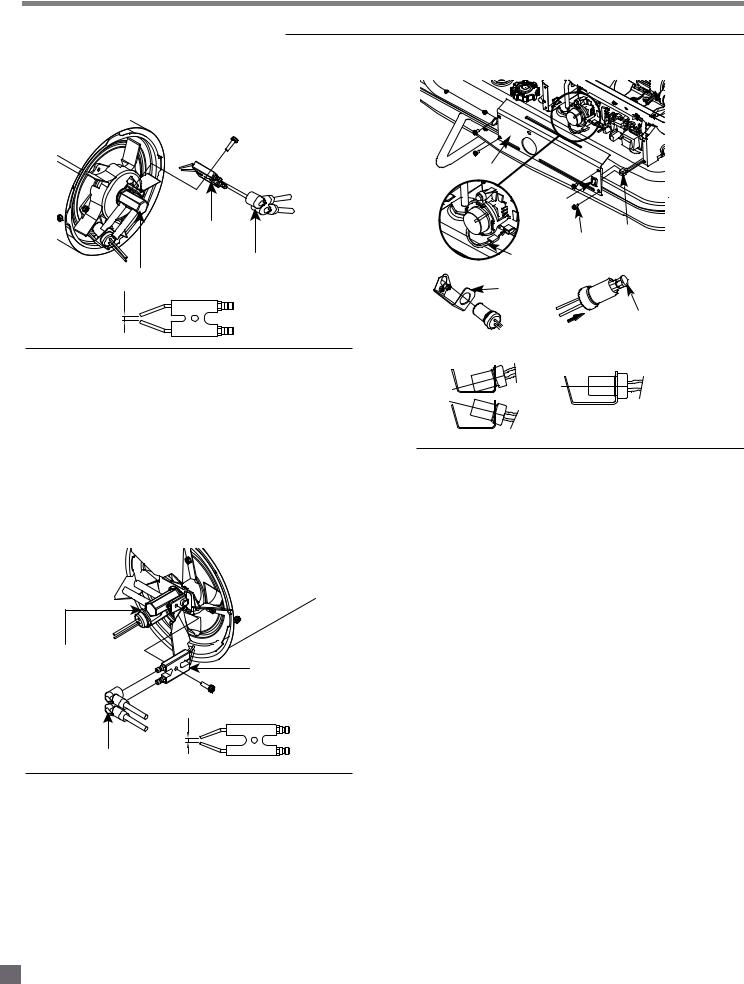
SPARK PLUG
CLEAN AND REGAP EVERY 600 HOURS OF OPERATION OR REPLACE AS NEEDED.
 Screw
Screw
|
Spark Plug |
|
Nozzle Adaptor |
Ignitor Wire |
|
|
||
GAP |
Spark Plug |
|
|
|
|
Figure 18 – Spark Plug Replacement
(For Models CP050EK-CP175FK)
-Remove upper shell (See Air Intake Filter, page 12).
-Remove fan (See Fan Blades, page 13).
-Remove ignitor wire from spark plug.
-Remove spark plug from nozzle adaptor using medium Phillips screwdriver.
-Clean and regap spark plug electrodes to 3.5mm gap.
-Reinstall spark plug to nozzle adaptor.
-Attach ignitor wire to spark plug.
-Reinstall fan and upper shell.
Nozzle Adaptor
Spark Plug
 Screw
Screw
Gap |
Spark Plug |
|
Ignitor Wire
Figure 19 – Spark Plug Replacement
(For Model CP210FK only)
-Remove upper shell (See Air Intake Filter, page 12).
-Remove fan (See Fan Blades, page 13).
-Remove ignitor wire from spark plug.
-Remove spark plug from nozzle adaptor using mediumphillips screwdriver.
-Clean and regap spark plug electrodes to 3.5mm gap.
-Reinstall spark plug to nozzle adaptor.
-Attach ignitor wire to spark plug.
-Reinstall fan and upper shell.
PHOTOCELL
Side Cover
Power
Switch
|
Screw |
Switch |
|
Wires |
|
|
Photocell Wires |
|
|
|
|
|
Bracket |
|
|
|
Photocell |
|
|
Lens |
|
Install Photocell |
|
Incorrect |
Correct |
|
Figure 20 – Photocell Replacement
CLEAN PHOTOCELL ANNUALLY OR AS NEEDED.
-Remove upper shell (See Air Intake Filter, page 12)
-Remove fan (See Fan Blades, page 13)
-Remove photocell from its mounting bracket.
-Clean photocell lens with cotton swab.
TO REPLACE: Remove side cover near power switch.
-Disconnect wires from power switch and remove side cover.
-Disconnect wires from circuit board and remove photocell.
-Install new photocell and attach wires to circuit board
-Replace switch wires to power switch and side cover.
-Replace fan and upper shell.
15

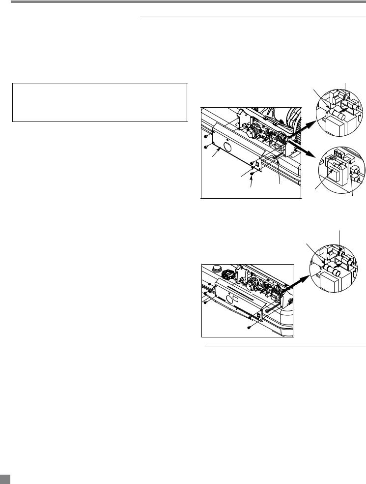
FUEL FILTER
CLEAN OR REPLACE TWICE PER HEATING SEASON OR AS NEEDED.
Fuel Filter
Fuel Line
Switch Wires
Screw
Side Cover
Power Switch
Figure 21 – Fuel Filter Replacement
-Remove side cover screws using medium Phillips screwdriver.
-Disconnect switch wires from power switch and remove side cover.
- -
- -
- Reinstall side cover.
MAINTENANCE (cont.)
PUMP PRESSURE ADJUSTMENT
Flat blade
Screwdriver
Pressure Gauge
Relief Valve
Figure 22 – Adjusting Pump Pressure
-Start heater (See “Operation”, page 9).
-Allow motor to reach full speed.
-
-Turn relief valve clockwise to increase pressure.
-Turn relief valve counterclockwise to decrease pressure.
-Set pump pressure to correct pressure for each model.
-Stop heater (see “Operation”, page 9).
Model |
Pump pressure |
CP050EK |
3.8 PSI |
CP075EK |
3.8 PSI |
CP125FK |
5.5 PSI |
CP175FK |
6.5 PSI |
CP210FK |
8.5 PSI |
NOTE: USE ONLY ORIGINAL EQUIPMENT REPLACEMENT PARTS. Use of alternate or third party components will void warranty and may cause an unsafe operating condition.
16
MAINTENANCE (cont.)
REPLACING FUSE
NOTE: The heater is fuse protected. If your heater fails to ignite, DO NOT
RETURN YOUR HEATER TO THE STORE.
Please follow the simple instructions below to inspect and change the fuse.
-Unplug heater.
-Remove side cover screws using medium Phillips screwdriver
Fuse Holder
 WARNING
Burn hazard!
-SHOCK HAZARD. To prevent presonal injury, unplug the power cord before replacing fuse.
-Remove fuse from fuse holder (See Figure 23).
-Replace fuse with enclosed fuse.
-Replace switch wires to power switch.
-Replace side cover.
NOTE: Specified fuse rating: AC 125/8A, part number 572447
|
Fuse |
|
Model: CP075EK |
Side Cover |
|
Power Switch |
|
Screw |
Switch Wires |
Fuse |
|
|
Fuse Holder |
Model: CP050EK
Fuse Holder
Fuse
Figure 23 – Replacing Fuse
17
 Loading...