

Page 1
Congratulations!
You have purchased the finest radiant heater available for the heating of livestock
in agricultural animal confinement buildings.
Your new L.B. White radiant heater incorporates the benefits from the most
experienced manufacturer of heating products using state-of-the-art technology.
We, at L.B. White, thank you for your confidence in our products and welcome any
suggestions or comments you may have...call us toll free at (800) 345-7200.
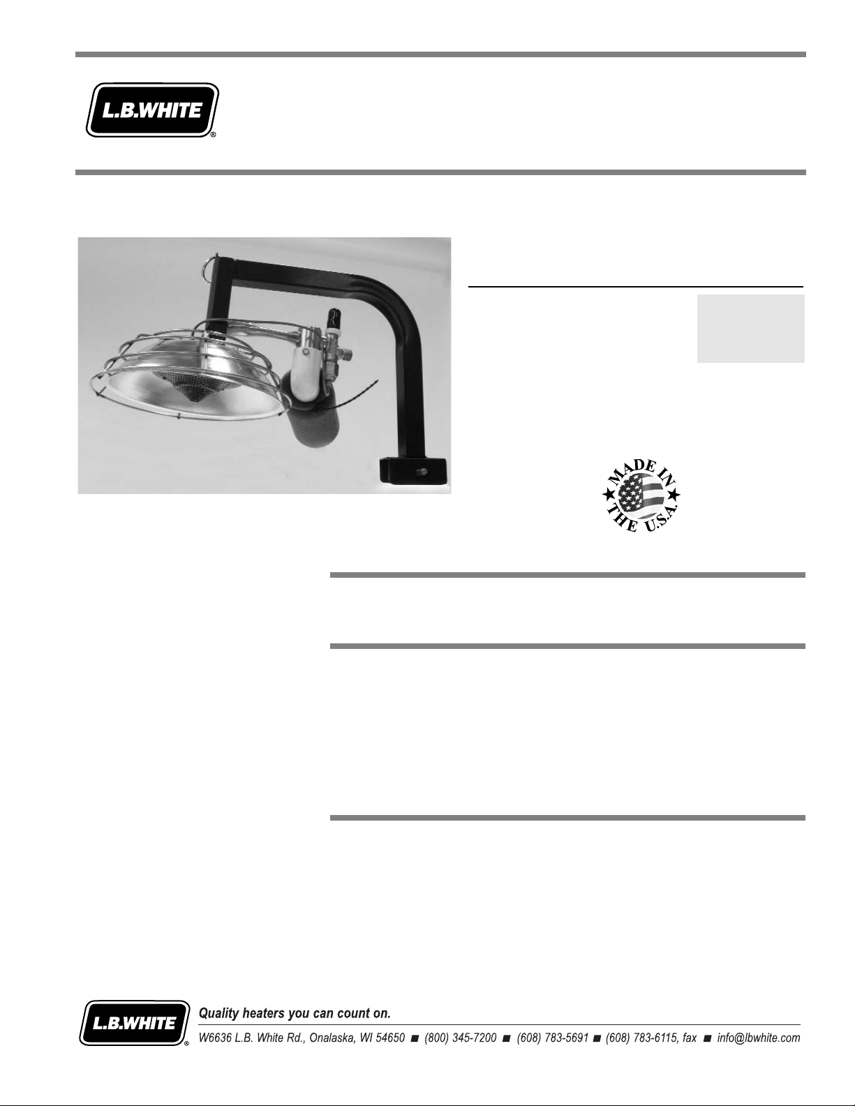
Owner’s Manual and Instructions
Modulating Infraconic
Agricultural Building Radiant Heaters
150-26814
MODEL OUTPUT (Btuh) FUEL
I3 2,800
Propane Vapor
Withdrawal
or Natural Gas
ATTENTION ALL USERS
This heater has been tested and evaluated by L.B. White Co. as a direct gas-fired
radiant heater designed specifically for use in farrowing operations in swine
confinement buildings. If you are considering using this product for any application
other than its intended use, then please contact your fuel gas supplier, or the
L.B. White Co., Inc.
Page 2

Page 3
WARNING
Fire and Explosion Hazard
■ Not for home or recreational vehicle use.
■ Installation of this heater in a home or
recreational vehicle may result in a fire or
explosion.
■ Fire or explosions can cause property
damage or loss of life.
FOR YOUR SAFETY
If you smell gas:
1. Open windows.
2. Don't touch electrical switches.
3. Extinguish any open flame.
4. Immediately call your gas supplier.
FOR YOUR SAFETY
Do not store or use gasoline or other
flammable vapors and liquids in the vicinity of
this or any other heater.
WARNING
Fire and Explosion Hazard
■ Keep solid combustibles a safe distance
away from the heater.
■ Solid combustibles include wood or paper
products, feathers, straw, and dust.
■ Do not use the heater in spaces which
contain or may contain volatile or airborne
combustibles.
■ Volatile or airborne combustibles include
gasoline, solvents, paint thinner, dust
particles or unknown chemicals.
■ Failure to follow these instructions may
result in a fire or explosion.
■ Fire or explosions can lead to property
damage, personal injury or loss of life.
GENERAL HAZARD WARNING
■ Failure to comply with the precautions and instructions provided with this heater, can result in:
— Death
— Serious bodily injury or burns
— Property damage or loss from fire or explosion
— Asphyxiation due to lack of adequate air supply or carbon monoxide poisoning
— Electrical shock
■ Read this Owner’s Manual before installing or using this heater.
■ Only properly-trained service people should repair or install this heater.
■ Save this Owner’s Manual for future use and reference.
■ Owner’s Manuals and replacement labels are available at no charge. For assistance, contact
L.B. White at 800-345-7200.
WARNING
■ Proper gas supply pressure must be provided to the inlet of the heater.
■ Refer to rating plate for proper gas supply pressure.
■ Gas pressure in excess of the maximum inlet pressure specified at the heater inlet can cause
fires or explosions.
■ Fires or explosions can lead to serious injury, death, building damage or loss of livestock.
■ Gas pressure below the minimum inlet pressure specified at the heater inlet may cause
improper combustion.
■ Improper combustion can lead to asphyxiation or carbon monoxide poisoning and therefore
serious injury or death to humans and livestock.
2
Page 4

This owner's manual includes all options and accessories
commonly used on or with this heater. However, depending
on the configuration purchased, some options and
accessories may not be included.
When calling for technical service assistance, or for other
specific information, always have the model number and
serial number available.
This manual will instruct you in the operation and care of
your radiant heater. Have your qualified installer review this
manual with you so that you fully understand the heater and
how it functions.
The gas supply line installation, and the repair, installation
and servicing of the heater requires continuing expert
training and knowledge of gas heaters and should not be
attempted by anyone who is not so qualified. See page 6
for definition of the necessary qualifications.
Contact your local L.B. White distributor or the L.B. White
Co., Inc. for assistance, or if you have any questions about
the use of the heater or its application.
The L.B. White Co., Inc. has a policy of continuous product
improvement. It reserves the right to change specifications
and design without notice.
SECTION
PAGE
General Information . . . . . . . . . . . . . . . . . . . . . . . . . . . . . . . . . . . . . . . . . . . . . . . . . . . . . . . . . . . . . . . . . . .3
Heater Specifications . . . . . . . . . . . . . . . . . . . . . . . . . . . . . . . . . . . . . . . . . . . . . . . . . . . . . . . . . . . . . . . . . .4
Safety Precautions . . . . . . . . . . . . . . . . . . . . . . . . . . . . . . . . . . . . . . . . . . . . . . . . . . . . . . . . . . . . . . . . . . . .5
Installation Instructions
General . . . . . . . . . . . . . . . . . . . . . . . . . . . . . . . . . . . . . . . . . . . . . . . . . . . . . . . . . . . . . . . . . . . . . . . . .7
Filter Assembly . . . . . . . . . . . . . . . . . . . . . . . . . . . . . . . . . . . . . . . . . . . . . . . . . . . . . . . . . . . . . . . . . . .8
Locating and Mounting the Heater . . . . . . . . . . . . . . . . . . . . . . . . . . . . . . . . . . . . . . . . . . . . . . . . . . .9
Safety Chain . . . . . . . . . . . . . . . . . . . . . . . . . . . . . . . . . . . . . . . . . . . . . . . . . . . . . . . . . . . . . . . . . . . .10
Hose Assembly . . . . . . . . . . . . . . . . . . . . . . . . . . . . . . . . . . . . . . . . . . . . . . . . . . . . . . . . . . . . . . . . . .10
Heater Control and Operation . . . . . . . . . . . . . . . . . . . . . . . . . . . . . . . . . . . . . . . . . . . . . . . . . . . . . .12
Start-Up Instructions . . . . . . . . . . . . . . . . . . . . . . . . . . . . . . . . . . . . . . . . . . . . . . . . . . . . . . . . . . . . . . . . .12
Shut-Down Instructions . . . . . . . . . . . . . . . . . . . . . . . . . . . . . . . . . . . . . . . . . . . . . . . . . . . . . . . . . . . . . . .13
Cleaning Instructions . . . . . . . . . . . . . . . . . . . . . . . . . . . . . . . . . . . . . . . . . . . . . . . . . . . . . . . . . . . . . . . . .13
Maintenance Instructions . . . . . . . . . . . . . . . . . . . . . . . . . . . . . . . . . . . . . . . . . . . . . . . . . . . . . . . . . . . . .14
Service Instructions
General . . . . . . . . . . . . . . . . . . . . . . . . . . . . . . . . . . . . . . . . . . . . . . . . . . . . . . . . . . . . . . . . . . . . . . . .15
Safety Gas Control Valve & Burner Orifice . . . . . . . . . . . . . . . . . . . . . . . . . . . . . . . . . . . . . . . . . . . .15
Thermostatic Head . . . . . . . . . . . . . . . . . . . . . . . . . . . . . . . . . . . . . . . . . . . . . . . . . . . . . . . . . . . . . .15
Thermocouple . . . . . . . . . . . . . . . . . . . . . . . . . . . . . . . . . . . . . . . . . . . . . . . . . . . . . . . . . . . . . . . . . . .16
Combsustion Cones and Gasket . . . . . . . . . . . . . . . . . . . . . . . . . . . . . . . . . . . . . . . . . . . . . . . . . . . .16
Gas Pressure Checks . . . . . . . . . . . . . . . . . . . . . . . . . . . . . . . . . . . . . . . . . . . . . . . . . . . . . . . . . . . . .17
Troubleshooting Guide . . . . . . . . . . . . . . . . . . . . . . . . . . . . . . . . . . . . . . . . . . . . . . . . . . . . . . . . . . . . . . . .18
Heater Component Function . . . . . . . . . . . . . . . . . . . . . . . . . . . . . . . . . . . . . . . . . . . . . . . . . . . . . . . . . . .22
Parts Identification
Parts Schematic . . . . . . . . . . . . . . . . . . . . . . . . . . . . . . . . . . . . . . . . . . . . . . . . . . . . . . . . . . . . . . . . .23
Parts List . . . . . . . . . . . . . . . . . . . . . . . . . . . . . . . . . . . . . . . . . . . . . . . . . . . . . . . . . . . . . . . . . . . . . . .24
Warranty Policy . . . . . . . . . . . . . . . . . . . . . . . . . . . . . . . . . . . . . . . . . . . . . . . . . . . . . . . . . . . . . . . . . . . . .25
Replacement Parts and Service . . . . . . . . . . . . . . . . . . . . . . . . . . . . . . . . . . . . . . . . . . . . . . . . . . . . . . . .25
Table of Contents
General Information
3
Page 5
4
Radiant Heater Specifications
SPECIFICATIONS
Model
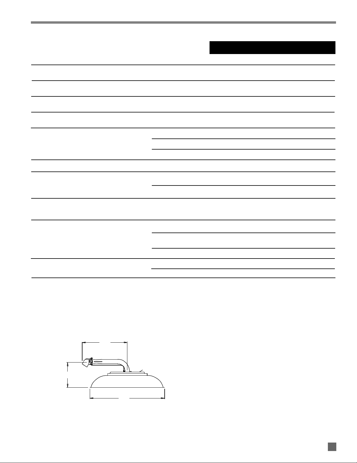
FIG. 1
Heater Dimensions
See Fig. 1
Fuel Consumption Per Hour
Minimum Safe Clearances to
Combustible Materials
Recommended Installation Height
24 in.
2.8 CFH
10 - 12 in. W.C.
35 CFM
5 PSIG
(1) This is a typical sensor height range for the modulating zone panel in a farrowing installations. Care should always be taken to
ensure that the sensor is sufficiently high as to not be damaged by the animal during operation.
"B"
"A"
"C"
Animal Occupied Zone Temperature
Control Sensor Location (1)
VERTICAL FROM FLOOR 18 in.
HORIZONTAL FROM CENTER OF BROODER 8 in.
I3
Maximum Input 2,800 BTUH
Ventilation Air to Support Combustion
Zone Control PROPANE GAS OR
Full Output Pressure NATURAL GAS
Zone Control, PROPANE GAS OR
Low Heat Pressure NATURAL GAS
“A” 7-5/8 in.
“B” 7 in.
“C” 3-1/2 in.
Net Weight 3-1/2 lbs.
PROPANE GAS .13 lbs./hr.
NATURAL GAS
24 in.above the creep mat
TOP OF SHROUD 2-1/2 ft.
VERTICALLY FROM POINT OF
COMBUSTION CONE
SIDES 2 ft.
Page 6
LP gas and natural gas have man-made odorants added specifically for detection of fuel gas leaks.
If a gas leak occurs, you should be able to smell the fuel gas.
THAT’S YOUR SIGNAL TO GO INTO IMMEDIATE ACTION!
■ Do not take any action that could ignite the fuel gas. Do
not operate any electrical switches. Do not pull any
power supply or extension cords. Do not light matches
or any other source of flame. Do not use your
telephone.
■ Get everyone out of the building and away from the area
immediately.
■ Close all propane gas tank or cylinder fuel supply
valves, or the main fuel supply valve located at the
meter if you use natural gas.
■ Propane gas is heavier than air and may settle in low
areas. When you have reason to suspect a propane
leak, keep out of all low areas.
■ Natural gas is lighter than air and can collect around
rafters or ceilings.
■ Use your neighbor’s phone and call your fuel gas
supplier and your fire department. Do not re-enter the
building or area.
■ Stay out of the building and away from the area until
declared safe by the firefighters and your fuel gas
supplier.
■ FINALLY, let the fuel gas service person and the
firefighters check for escaped gas. Have them air out
the building and area before you return. Properly
trained service people must repair the leak, check for
further leakages, and then relight the heater for you.
■ Some people cannot smell well. Some people cannot
smell the odor of the man-made chemical added to
propane or natural gas. You must determine if you can
smell the odorant in these fuel gases.
■ Learn to recognize the odor of propane gas and natural
gas. Local propane gas dealers and your local natural
gas supplier (utility) will be more than happy to give you
a “scratch and sniff” pamphlet. Use it to become
familiar with the fuel gas odor.
■ Smoking can decrease your ability to smell. Being
around an odor for a period of time can affect your
sensitivity to that particular odor. Odors present in
animal confinement buildings can mask fuel gas odor.
■ The odorant in propane gas and natural gas is colorless
and the intensity of its odor can fade under some
circumstances.
■ If there is an underground leak, the movement of gas
through the soil can filter the odorant.
■ Propane gas odor may differ in intensity at different
levels. Since propane gas is heavier than air, there may
be more odor at lower levels.
■ Always be sensitive to the slightest gas odor. If you
continue to detect any gas odor, no matter how small,
treat it as a serious leak. Immediately go into action as
discussed previously.
FUEL GAS ODOR
ODOR FADING -- NO ODOR DETECTED
ATTENTION -- CRITICAL POINTS TO REMEMBER!
■ Propane gas and natural gas have a distinctive odor.
Learn to recognize these odors. (Reference “Fuel Gas
Odor” and “Odor Fading” sections above.
■
If you have not been properly trained in repair and service
of propane gas and natural gas fueled heaters, then do
not attempt to light the heater, perform service or repairs,
or make any adjustments to the heater on a propane (LP)
gas or natural gas fuel system.
■ Even if you are not properly trained in the service and
repair of radiant heaters, ALWAYS be consciously aware
of the odors of propane gas and natural gas.
■ A periodic “sniff test” around the heater or at the
heater’s joints; i.e. hose, connections, etc., is a good
safety practice under any conditions. If you smell even
a small amount of gas, CONTACT YOUR FUEL GAS
SUPPLIER IMMEDIATELY. DO NOT WAIT!
5
WARNING
■ Do not use this radiant heater for heating human living
quarters.
■ Do not use in unventilated areas.
■ The flow of combustion and ventilation air must not be
obstructed.
■ Proper ventilation air must be provided to support the
combustion air requirements of the heater being used.
■ Refer to the specification section of the Owner’s
Manual, heater’s dataplate, or contact PSI to determine
combustion air ventilation requirements of the heater.
■ Lack of proper ventilation air will lead to improper
combustion.
■ Improper combustion can lead to carbon monoxide
poisoning in humans leading to serious injury or death.
Symptoms of carbon monoxide poisoning can include
headaches, dizziness and difficulty in breathing.
■ Symptoms of improper combustion affecting livestock
can be disease, lower feed conversion, or death.
Asphyxiation Hazard
Safety Precautions
Page 7
1. Do not attempt to install, repair or service this heater
or the gas supply line unless you have continuing
expert training and knowledge of gas heaters.
Qualifications for service and installation of this
equipment are as follows:
QUALIFICATIONS FOR
SERVICING AND INSTALLATION:
a. To be a qualified gas heater service person, you
must have been trained in gas-fired heater
servicing, repair and also have sufficient
experience to allow you to troubleshoot, replace
defective parts, and test heaters in order to get
them into a continuing safe and normal operation
condition. You must completely familiarize
yourself with each model heater by reading and
complying with the safety instructions, labels,
owner’s manual, etc. that is provided with each
heater.
b. To be a qualified gas installation person, you must
have sufficient training and experience to handle
all aspects of installing, repairing and altering gas
lines, including selecting and installing the proper
equipment, and selecting proper pipe size to be
used. This must be done in accordance with all
local, state and national codes as well as the
manufacturer’s requirements.
2. All installations or applications of L. B. White Co.,
Inc.’s radiant heater and associated zone control
panel should meet the requirements of local, state
and national L.P. gas and natural gas, electrical and
safety codes. Your gas supplier, local licensed
electrician, local fire department and government
agencies can help you determine these requirements.
In the absence of local codes, comply with the
following:
a. Installations in the U.S.A.:
-- ANSI/NFPA 58, latest edition, Standard for
Storage and Handling of Liquefied
Petroleum Gas and/or
-- ANSI Z223.1/NFPA 54, National Fuel Gas
Code
b. Installations in Canada:
-- CAN1-B149.1 or CAN1-B149.2 Installation
Codes
-- CSA C22.1 Part 1 Standard Canadian Electrical
Codes, CSA C22.2 No.3 Electrical Features of
Fuel Burning Equipment
3. If at any time you notice something unusual about the
operation of your heater such as gas odor,
overheating, flames other than in the combustion
cone area, etc., evacuate the area immediately and
call your fire department and your gas service agency.
Get assurances from the fire department that the
area is free of gas before you attempt to relight the
heater.
4. The components on the heater that call for hand
operation should work with hand pressure only. If
more force is required, have a qualified gas heater
service agency replace the complete part. Do not
attempt to repair.
5. Do not block air intakes or discharge outlets of the
heater. Doing so may cause improper combustion or
damage to the heater components leading to
property damage or animal loss.
6. Do not move, handle, or service the heater while in
operation or connected to fuel supply.
7. Do not locate fuel supply hoses within the heater’s
heating zone.
8. All gas hose assemblies must be inspected on a
regular basis. This should be done at least once a
year, or when the farrowing room has been cleaned
after each turn. If it is evident there is excessive
abrasion or wear, or if the hose is cut, it must be
replaced prior to heater being put into operation. The
hose assembly shall be protected from animals,
building materials, and contact with hot surfaces
during use. The hose assembly shall be that
specified by the manufacturer. See parts list.
9. Check for gas leaks and proper function upon
installation, before building repopulation and when
relocating.
10. If the gas flow is interrupted and the burner flame is
extinguished, immediately shut off the gas. Do not
relight the heater until you are sure that all of the gas
that may have accumulated through the heater has
cleared away. Do not relight the heater until at least
five minutes have passed.
11. If the heater is to be relocated, make sure that all gas
connections are capped and the gas supply is shut
off. All connection points must be leak checked after
disconnection and after reconnection.
6
WARNING
Burn Hazard
■ The heater’s combustion cones and canopy are
extremely hot during operation and shortly after
shutting down.
■ Always be aware of your proximity to the heater and
avoid contact with its hot surfaces during or shortly
after operation.
■ Failure to follow this warning can result in burns
leading to severe injury.
Safety Precautions
Page 8

1. Read all safety precautions and follow L.B. White
recommendations when installing this heater. If
during the installation or relocating of the heater, you
suspect that a part is damaged or defective, call a
qualified service agency for repair or replacement.
2. Gas pressure and regulation requirements
-- Infraconic heaters require a regulated gas supply
of 5 PSIG.
-- Exceeding the gas inlet pressure rating can result
in poor performance and unreliable operation.
-- See page 4 of this manual for information on gas
pressures relating to specific models.
-- Each room of heaters must have an adjustable
high pressure regulator installed for proper
control of pressures.
-- L.P. Gas: the regulator must be capable of
handling a maximum inlet pressure of 10 psi,
while supplying an outlet pressure of 5 psi
nominal.
-- Natural gas: the regulator must be installed to
supply an outlet pressure of 5 psi nominal.
Part number 09703 can be ordered for use on
either fuel gas.
3. The heater’s gas regulator (with pressure relief valve)
should be installed outside of building. Any
regulators inside the buildings must be properly
vented to the outside. Local, state and national codes
always apply to regulator installation. Natural gas
regulators with a vent limiting device may be mounted
indoors without venting to outdoors.
4. Any regulator mounted outside the building be
protected against the weather, particularly ice
formation. Ice formation can lead to
overpressurization of the regulator and subsequent
gas leaks. See codes covering proper protection.
5. Position the heater properly before use in accordance
with requirements for combustible clearances, crate
divider panel clearance, tilt angle, and to protect the
heater from livestock.
6. Position the gas hose outside of the hot zone directly
above the heater. Position the gas hose to avoid any
contact with the hot surfaces of the heater.
7. The heater must be installed properly to prevent heat
stress to the adult animal.
8 The heater is designed for mounting over farrowing
crate divider panels made of metal, or more
commonly used PVC or ABS materials. When installed
over a common divider panel, one heater will provide
heat to piglets in adjacent crates. As standard the
heater ships for mounting to a metal divider panel. Kit
# 26769 is used for mounting the heater to PVC or
ABS panels.
9. Insure that all accessories that ship with heater have
been installed. This pertains to gas hose, safety
chain hanging kit, and if applicable, base mount for
installation on PVC/ABS panels.
10. Always use pipe joint compound that is resistant to
liquefied petroleum gas and natural gas.
7
Installation Instructions
GENERAL
12. Inspect all heaters after room turn, or before
repopulation. Such inspection should consist of, but
is not limited to, the following points of action:
-- Insure proper clearance to combustible materials.
-- Check for general cleanliness. Clean if necessary.
-- Check gas hose connections for tightness.
13. A qualified service person shall inspect the heater
and its gas train at least on an annual basis. This
should consist of, but is not limited to, the following
points of action:
-- Start-up and shut down of the heaters and zone
control panel to test for proper operation.
-- Leak check of all pipe joints and hose connections.
-- Thorough cleaning of the exterior of the heater, its
inlet venturi, combustion cones and filter.
-- Thorough inspection of the heater’s component
parts for corrosion, stripped threads, etc. with
subsequent parts replacement as necessary.
-- Gas pressure checks.
14 The heater’s gas hose and quick disconnect are
equipped with excess flow valves. The excess flow
valve will limit gas flow in the event the gas hose is
cut or ruptured.
15. Turn off the gas supply when the heater is not in use.
Page 9

8
11. Check all connections for gas leaks using approved
gas leak detectors. Gas leak testing is performed as
follows:
-- Check all pipe connections, hose connections,
fittings and adapters upstream of the gas
control with approved gas leak detectors.
-- In the event a gas leak is detected, check the
components involved for cleanliness and
proper application of pipe compound before
further tightening.
-- Tighten the gas connections as necessary to
stop the leak.
-- After all connections are checked and any
leaks are eliminated, light the heater.
-- Stand clear while the heater ignites to prevent
injury caused from hidden leaks that could
cause flashback.
-- With the heater in operation, check all
connections, hose connections, fittings and
joints as well as the gas control valve inlet and
outlet connections with approved gas leak
detectors.
-- If a leak is detected, check the components
involved for cleanliness in the thread areas
and proper application of pipe compound
before further tightening.
-- Tighten the gas connection as necessary to
stop the leak.
-- If necessary, replace the parts or components
involved if the leak cannot be stopped.
-- Ensure all gas leaks have been identified and
repaired before proceeding.
12. A qualified service agency must check for proper
operating gas pressures upon installation of the
heaters.
13. Use the proper gas supply line to assure proper
functioning of the heaters. Typically, 3/4 in. ID black
iron pipe is used to supply gas to the inlet of the zone
control panel with 1/2 in. ID black iron pipe used to
convey the gas to the heaters. However, always
consult your fuel gas supplier, or the L. B. White Co.,
Inc. for proper line sizing and installation.
14. The heater is designed for either propane vapor withdrawal or natural gas, depending on model number.
Do not use this heater in an propane liquid
withdrawal system. Do not permit propane in liquid
form to enter the heater at any time.
15. The corrosive atmosphere present in animal
confinement buildings can cause component failure
or heater malfunction. The heater should be
periodically inspected and cleaned in accordance
with the Maintenance and Cleaning Instructions in
this manual. Make sure that livestock is protected by
a back up alarm system that limits high and low
temperatures and also activates appropriate alarms.
16. Take time to understand how to operate and
maintain the heater using this Owner’s Manual.
Make sure you know how to shut off the gas supply to
the building and to the individual heaters. Contact
your gas supplier if you have any questions.
17. Any defects found in performing any of the service
procedures must be eliminated and defective parts
replaced immediately. Retest the heater before
placing it back into service.
FILTER
1. See Fig. 2 for attaching filter to heater.
A. Push filter completely onto air intake.
B. Attach filter to intake by using beaded cable tie.
Ensure cable tie securely fastens filter to air intake
of heater
2. The filter may be removed by loosening the beaded
cable tie.
FIG. 2
WARNING
Fire and Explosion Hazard
■ Do not use open flame (matches, torches, candles,
etc.) in checking for gas leaks.
■ Use only approved leak detectors.
■ Failure to follow this warning can lead to fires or
explosions.
■ Fires or explosions can lead to property damage,
personal injury or death.
Page 10

Locating
The heater is designed to provide radiant heat to the entire
creep mat or creep area on both sides of the crate divider.
To properly utilize the heater, the producer must determine:
a. Desired position of the heat zone relative to the sow
b. Location of the creep mat relative to the sow.
Individual preferences will vary from producer to producer.
Nonetheless consideration must be given to prevention of heat
stress on the sow. See Fig. 3 for typical heater location.
Regardless of mat location, the heater is mounted
6 - 8 inches from center of mat (away from sow’s head) to
provide proper heat coverage of the mat.
FIG. 3
Mounting
To steel crate panels
a. Position the heater onto the crate panel at the desired
location.
b. Mark the location using the heater’s saddle bracket
mount as a template. See Fig.4. Remove heater.
FIG. 4
c. Using the drill template from the safety chain kit
(included) position its holes at the locations previously
marked. Drill 1/8 in. pilot holes at both sides. See Fig.5.
FIG. 5
d. Remove and drill 5/16 in. holes through both sides of
the metal crate panel.
e. Position the heater back onto the panel. Align the holes
in the heater’s saddle bracket with the drilled holes in
the panel. Lock the heater into place by pushing the
retaining pin completely through both sides of the
bracket. See Fig.6. Proceed to Safety Chain Installation
Instructions
FIG. 6
To PVC or ABS crate panels.
All installations with PVC or ABS crate panels must use
kit # 26769, which includes base mounts and hardware
to install two heaters. The base mount must be used as
it supports the heater while acting as a heat shield
a.. Position the heater to the base mount using the
retaining pin.See Fig.7, next page.
-- Saddle bracket of heater aligns to either set of upper
holes at ends of base mount.
-- Heater canopy must be positioned over the base
mount. See Fig.7.
MARK LOCATION BOTH SIDES
DRILL1/8 IN. PILOT HOLES
BOTH SIDES
Locating and Mounting the Heater
9
DIVIDER PANEL
CREEP AREA
CENTER OF MAT
DIVIDER PANEL
CREEP AREA
CENTER OF MAT
6-8 INCHES
6-8 INCHES
THE MOUNTING SUPPORT OF THE HEATER IS DESIGNED WITH PROPER TILT
ANGLE TO ENSURE THAT MAT AREA IS FULLY COVERED BY RADIANT HEAT
MINIMUM 24 IN.
CLEARANCE WITH
HEATER DIRECTED TO
CENTER OF CRATE
Page 11

The safety chain hanging kit must be installed. Its purpose is
to provide a safety in the event the heater is accidentally
detached from its mounting on the crate panel. It also
provides a means to hang the heater out of the way during
room depopulation and cleaning.
1. Connect key ring to toggle bolt, and safety latch and
chain to key ring. See Fig. 9.
2. Drill a 5/8 in. diameter hole into the ceiling directly
above the heater and secure the toggle bolt with
hardware in place. See Fig.9
FIG. 9
3. Connect opposite end of chain to key ring on heater
mounting frame. Take up any slack, and cut off excess
chain.
4 When cleaning the room or depopulating, detach the
heater’s safety pin and connect the heater’s key ring to
the snap latch at the toggle bolt. See Fig.10
FIG. 10.
FIG. 7
b.. Locate the heater with mount to the planned position on
the crate panel. Push the assembly firmly onto the panel.
c. Using the lower base holes as templates, drill 5/16 in.
holes through the divider panel , both sides. See Fig.8.
Secure the base mount to the panel with nuts and bolts
included. Proceed to Safety Chain Installation
Instructions.
FIG. 8
Safety Chain
(part 26771)
10
LOWER HOLES
INSTALL NUTS AND BOLTS BOTH
ENDS
HOSE ASSEMBLY
TO GAS SUPPLY
MANUAL SHUT-OFF
BUSHING
HOSE 1/4" RIGID X SWIVEL
W/ EXCESS FLOW VALVE
TO GAS SUPPLY
MANUAL SHUT-OFF
HOSE 1/4" Q.C. X SWIVEL NUT
MALE QUICK CONNECT
FEMALE QUICK CONNECT
W/ EXCESS FLOW VALVE
COLLAR
MALE END
A
-- PULL BACK COUPLING COLLAR
TO REMOVE DUST CAP.
-- REMOVE DUST CAP FROM
MALE END OF HOSE.
-- FIRMLY PUSH MALE HOSE END
INTO COUPLING.
-- RELEASE COLLAR.
ENSURE MALE HOSE END IS
SECURELY LOCKED INTO COUPLING
TO GAS INLET AT HEATER
FIG. 11.
Page 12

Proper temperature management is needed when using the I-3
radiant heater. The creep area, which is the comfort zone for
piglets, is managed independently from the room temperature.
The room’s temperature will be lower than the temperature
needed for the creep area. Lower room temperatures create two
benefits:
-- Less fuel/energy consumption
-- Increased sow feed intake which creates higher
weaned weights.
Managing the heat in this manner provides proper growing
environment for piglets, allowing them to keep warm without
heating the sow.
Temperature Management
I-3 modulating heaters heaters are normally operated and
controlled by the use of a non- electric zone control panel.
Contact the L.B.White Co.if you are considering connecting I-3
modulating heaters to a building controller.
Zone Control Panel (See Fig.12)
The zone control panel is a non-electric, modulating design for
stand alone heater operation, and controls the following quantity
of heaters depending on fuel type.
The zone panel is a “heat- to- demand” operation system. It will
operate all I-3 heaters between 10% to 100% to satisfy the
temperature requirements established by the zone panel’s
thermostatic head.
The zone control panel must be mounted to a flat, stable wall
inside the building. Use lag screws provided. Ensure that the
thermostatic control module is not exposed to outside air
temperatures. Exposure of the thermostatic control module to
outside air temperatures may cause the heater to provide
unwanted heat.
Refer to Fig.12 for location of zone panel’s sensor. The sensor
must be located within a middle crate of a row of crates,
representing the average condition of the room. Do not locate the
sensor in a crate at the end of a row, or where could be
influenced by things such as cooler inlet ventilation air, exhaust
fans, opening of doors, etc.
CAPILLARY
DIVIDER
PANEL
18 IN.
CRATECRATE
SENSOR 8 IN. FROM
SIDE OF PANEL AND 18
IN. FROM PEN DECK
GAS HOSE TO
GAS SUPPLY
8 IN.
HEATER CONTROL and OPERATION
Modulating System
Medium
Model and Capacity
Heat Output Fuel Panel
Quantity
I3 L. P. Gas 83
(2,800 BTUH) Natural Gas 48
FIG. 12
11
ZONE PANEL
THERMOSTATIC HEAD
Page 13

Follow these start-up instruction steps for initial start-up
before room repopulation when using the standard zone
control panel. For normal start-up, simply turn the
thermostatic head above room temperature.
1. Adjust the zone panel’s thermostatic head to its
maximum temperature setting. See Fig. 13. Wait
15 - 30 seconds to allow gas supply pressure to fill
the line and stabilize.
2. Open all gas supply valves to the heater(s) and check
for gas leaks at all connections using approved leak
detectors.
3. Allow 10 seconds for gas pressure to stabilize within
the gas hose’excess flow valve before lighting the
heater.Open all gas supply valves to the heater(s) and
check for gas leaks.
FIG. 13
4. Fully depress the button on the safety control valve
while applying flame to the inner cone point. See
Fig.14. (Remove the cap if stiff. Ensure cap is
replaced after lighting). Keep the button fully
depressed for about 30 seconds. Release rhe safety
control button. Allow outer combustion cone to heat
up completely.
FIG. 14
5. Adjust the temperature by decreasing the setpoint on
the thermostatic head to the desired temperature.
The heater will modulate from low heat to high heat
based upon this setting.
INDICATOR
100ºF
38ºC
THERMOSTATIC
HEAD
12
Lighting Instructions
WARNING
Fire or Explosion Hazard
■ Do not force the safety gas control valve button.
■ Use only your hand to depress the gas control button.
Never use any tools.
■ If the button will not depress by normal hand
pressure, the control should be replaced by a
qualified service person.
■ Force or attempted repair may result in fire or
explosion, causing property damage, severe injury, or
death.
To reduce temperature, turn down the thermostatic control
on the zone panel, or reduce temperature requirements of
room controller.
To shut down the heaters for maintenance, cleaning or
service:
1. Shut off all gas supply valves to the heaters.
2. Allow heaters to burn off fuel gas remaining in the
gas supply line.
3. Turn down the thermostatic head or room
controller to minimum setting.
Shut-Down Instructions
APPLY FLAME
SAFETY
CONTROL
Page 14

Cleaning Instructions
13
This heater is used in the farrowing environment where the
animals are turned approximately every 21 days and the
rooms are typically pressure washed between turns.
See the following for cleaning the heater bewtween turns.
For longer term cleaning requirements, see the Maintenance
Section of this manual.
BETWEEN TURNS
Shut the heaters down when cleaning the room.
The outside of the heater can be subjected to the mist or
rain that occurs from pressure washing the room. Do not
pressure wash the heater directly. If external cleaning is
desired due to biosecurity requirements, the heater may also
be washed off with water spray at standard faucet water
pressure.
If the filter gets wet during the washing process, then
squeeze the water out of the filter.
After the heater has been exposed to water during the
cleaning process, light the heater and let it dry off.
CAUTION
■ Disinfectants used in agricultural animal
confinement buildings may contain
chemicals damaging to components of the
heater.
Page 15

1. Have your gas supplier check all gas piping annually
for leaks or restrictions in gas lines. Also, at this time
have your gas supplier clean out the sediment trap
on the zone control panel of any debris that may have
accumulated.
2. Regulators can wear out and function improperly.
Have your gas supplier check the date codes on all
regulators installed and check delivery pressures to
the appliance to make sure that the regulator is
suitable for continued use.
3. Regulators must be periodically inspected to make
sure the regulator vents are not blocked. Debris,
insects, insect nests, snow, or ice on a regulator can
block vents and cause excess pressure at the
appliance.
4. For safety as well as for optimum performance at the
heater, it is necessary to keep the inside and the
outside of the heater free of dust, dirt or any
combustible material.
5. Immediately replace components which show signs
of rust or corrosion.
6. If any warning or instruction labels, dataplates, etc.
become lost or hard to read, replace them
immediately. Do not operate the heater until you
have all instructions and can read and understand
them.
7. Check overall condition of heater for cracked or
damaged components, loose screws or bolts, etc.
Replace any suspect components.
8. Check all hose and tubing assemblies for cracks,
abrasions or ruptures. Replace any hoses that are
suspect.
9. The heater should be cleaned every 6 months, the
filter every 3 months. Cleaning the the heater and
filter is essential for proper heater operation.
Cleaning frequency is dictated by severity of dust in
room
Problems associated with lack of cleaning are:
■ Black soot on inside of canopy.
■ Gas backflashing in venturi tube or injector body.
■ Burner flame appearing beyond outer cone.
FIG. 15
CLEANING THE HEATER
Use water at standard faucet pressure. DO NOT USE HIGH
PRESSURE WASHERS!
a. Remove the filter.
b. Spray water up into the cones to wash out the build
up of dust in the cones and the venturi tube. Work
your way around the entire cone assembly. Reverse
the process and run water through the air intake and
out through combustion cones. See Fig. 15.
c. Repeat until water runs clean.
d. Install filter.
e. Light the heater to allow drying.
CLEANING THE FILTER
- Remove filter and shake off excess dust.
- Use water at standard faucet pressure
pressure.
--Do not use high pressure water, or a
washing machine. Filter material damage
may occur.
- Squeeze out excess water from the filter before
installation.
- Let filter dry before lighting heater.
Maintenance Instructions
AIR INTAKE
COMBUSTION CONES
14
VENTURI TUBE
Page 16

Service Instructions
1. Close the fuel supply valve to the heater before
servicing unless it is necessary to have it open for
your service procedure.
2. For reassembly, reverse the respective service
procedure. Ensure gas connections are tightened
securely.
3. After servicing, start the heater to ensure proper
operation and check for gas leaks.
4. Replace the burner orifice if it becomes plugged with
dirt. Do not use files, drills, broaches, etc. to clean the
orifice hole. Doing so will enlarge the hole, causing
combustion or ignition problems.
WARNING
Burn Hazard
■ Heater surfaces are extrememly hot for a period of
time after the heater has been shut down.
■ Allow the heater to cool before performing service,
maintenance, or cleaning.
■ Failure to follow this warning will result in burns
causing injury.
GENERAL
WARNING
Fire and Explosion Hazard
■ Do not disassemble or attempt to repair any heater
components or gas train components.
■ All component parts must be replaced if defects are
found.
■ Failure to follow this warning will result in gas leaks
leading to fire or explosions, causing property
damage, injury, or death.
SAFETY GAS CONTROL VALVE & BURNER ORIFICE
1. Remove gas hose and disconnect thermocouple at
safety control valve.
2. Remove air intake retaining screw.
3. Pull gas control assembly from heater.
4. To remove orifice, use a 1/4 in. nut driver. Replace
orifice if plugged with dust.
FIG. 16
SCREW
AIR INTAKE
BURNER ORIFICE
ATTACHMENT
KNOB
THERMOSTATIC
HEAD
THERMOSTATIC HEAD
The head assembly on the zone panel includes the
adjustable thermostatic head, capillary and sensor. The
Part # for the thermostatic head is 23662, with 26 ft.
capillary.
The symptom of component failure would be the heater
staying at full heat output and not responding to lower
temperature setting of thermostatic head.
1. Loosen the attachment knob located at the
thermostatic head and valve body, and discard head.
See Fig. 17.
2. Securely tighten the knob of the replacement head to
the valve body, otherwise temperature sensing will be
affected.
FIG. 17
15
Page 17

THERMOCOUPLE
HOLE
STUD
INJECTOR TUBE
NUT
THERMOCOUPLE
LOCATION BRACKET
1. Remove the thermocouple bracket nut. See Fig. 18.
2. Pull the thermocouple from its mounting location.
3. Disconnect thermocouple from pilot safety gas control
valve. Replacement thermocouple will include a
factory installed locator bracket with retaining nut.
FIG. 18
THERMOCOUPLE
16
1 Remove all nuts from the three burner screws. See
Fig.19.
2. Remove thermocouple from burner.
3. Using pliers, straighten the tab at the top of both truss
clips. The truss clips will drop to the cone side of the
heater.
Fig. 19
\
4. Slide the canopy guard away from the burner top.
5. Slide the outer cone from the retainer slots. Remove
the three bolts and spacers. See Fig.20.
Fig. 20
6. Remove the burner plate and inner cone for access to
the burner gasket. See Fig.21. A replacement gasket
must be installed whenever the inner cone is removed.
Clean the surface to which the gasket is located
beforehand.
Fig. 21
7. When reassembling, ensure:
-- Inner cone weld seam aligns to burner plate notch.
See. Fig.20.
-- All burner nuts and screws are securley tightened.
COMBUSTION CONES and GASKET
TRUSS CLIP
TAB
TRUSS CLIP
TAB
NUT
GASKET
BOLTS
CONE WELD SEAM
ALIGNED TO NOTCH
Page 18

TEST KIT HOSE
FUEL SUPPLY VALVE
(OPEN THIS VALVE TO
USE PRESSURE GAUGE)
GAS SUPPLY HOSE
GAS INLET OF HEATER
PRESSURE GAUGE KIT
20736
OPEN
FIG. 22
A. Preparation
1. Obtain an L.B. White pressure gauge test kit Part No. 20736.
2. Close the fuel supply valve to the heater.
3. Brush or blow off any dust and dirt on or in the vicinity
of the safety control valve.
4. Disconnect the gas hose from the heater.
B. Gauge Installation
1. Connect the pressure test kit between the heater and
its gas supply hose as shown in Fig. 22. Insure both
gas shut-off valves on the test kit are in the closed
position when connecting the kit to the heater and
gas supply.
2. Open the fuel supply valve to the heater.
3. Open only the gas shut-off on the test kit to which the
gas supply hose is connected.
4. Adjust the thermostatic head to its maximum setting
and light the heater.
C. Reading Pressures
1. With all of the heaters within the zone operating at
full heat output and at minimum heat, the pressure
gauge should read the pressure specified on the
dataplate of the zone panel.
2. Does the reading on the gauge of the test kit agree
with that specified on the dataplate? If so, then no
further checking or adjustment is required. Proceed
to Section D.
3. If the pressure does not agree with that specified on
the dataplate, then the regulator controlling gas
pressure to the heater requires adjustment.
D. Completion
1. Once gas pressure has been confirmed and/or
properly set, close the fuel supply valve to the heater
and allow the heater to burn off any gas remaining in
the gas supply hose.
2. Remove the gauge kit and reconnect the heater’s gas
hose to the heater.
3. Open the main fuel supply valves to the heater. Light
the heater.
4. Set thermostatic head to desired temperature.
GAS PRESSURE CHECKS
17
Page 19

18
READ THIS ENTIRE SECTION BEFORE
BEGINNING TO TROUBLESHOOT PROBLEMS.
The following troubleshooting flow charts provide systematic
procedures for isolating heater problems. The charts are
intended for use by a QUALIFIED GAS HEATER SERVICE
PERSON. DO NOT SERVICE THE HEATER UNLESS YOU HAVE
BEEN PROPERLY TRAINED.
TEST EQUIPMENT REQUIRED
The following pieces of test equipment will be required to
troubleshoot this system with minimal time and effort.
• Digital Multimeter - For measuring DC voltage when using
thermocouple diagnostic kit.
• Millivolt Test Kit - (Part # 21188) When used with a
standard digital multimeter, this kit allows testing of the
thermocouple and electromagnetic power unit.
• Pressure Gauge - (Part # 20736) For checking inlet
pressures to the heaters.
INITIAL PREPARATION
-- Inspect heater for damage.
-- Clean heater as necessary.
Heater Problems
Page
1. Inner combustion cone will not light . . . . . . . . . . . . . . . .19
2. Outer combustion cone does not heat up on
high thermostatic head setting . . . . . . . . . . . . . . . . . . . .19
3. Inner combustion cone lights,
but will not stay lit . . . . . . . . . . . . . . . . . . . . . . . . . . . . . . .20
4. Heater backflashes gas through injector body
air inlet . . . . . . . . . . . . . . . . . . . . . . . . . . . . . . . . . . . . . . .21
5. Heater does not return to
low heat . . . . . . . . . . . . . . . . . . . . . . . . . . . . . . . . . . . . . . .21
Components should be replaced only after each step has
been completed and replacement is suggested in the flow
chart.
Troubleshooting Guide
WARNING
Burn Hazard
■ Troubleshooting this system may require operating the
heater with the burner on. Use extreme caution when
working on the heater.
■ Failure to follow this warning will result in burns
causing severe injury.
Page 20

Is
there a
blockage in the
venturi tube?
19
Problem 1
Inner
combustion
cone will not
lght
Is
thermostatic
head set to
maximum
setting?
Is the
orifice plugged?
Turn thermostat
up to Its
maximum
setpoint.
Replace the primary burner
orifice.
Yes
No
Yes
Yes
Yes
Is the inner
combustion cone
plugged?
Is there air or
a blockage in the
gas hose or
gas piping?
Remove blockage with compressed
air or replace the gas hose or pipe
section. Bleed off any air from the
gas line.
Clean the heater.
Clean the heater.
No
No
No
Is proper
gas pressure
supplied to the
zone panel or
heater?
Provide 5 PSIG
gas pressure.
Yes
No
Are all Fuel
Supply Valves to
Heater Open?
Open all fuel
supply valves.
Yes
No
Defective
safety control valve.
Replace the safety
control valve.
Yes
No
Problem 2
Outer
combustion
cone does
not heat up
on high
thermostat
setting.
Has proper gas pressure
been checked to the
heater?
Check for proper gas
pressure to the heater.
Proper pressure at high
heat should read 5 PSIG.
Yes
No
Is
orifice plugged?
Replace it.
Yes
No
A. Remove thermostatic head from valve
body at zone panel. If outer cone lights,
replace the thermostatic head and
sensor assembly.
B. If outer cone still does not light, replace
thermostatic head valve body.
Are there
blockages in
gas hose, piping,
or venturi tube?
Remove the
component
and clean It.
Yes
No
Page 21

20
Problem 3
Inner
combustion
cone lights,
but will not
stay lit
Did you
allow sufficient time
for the thermocouple
to warm up?
Allow 30 - 60
seconds before
releasing pilot
button.
Remove the component and
clean It.
Yes
No
Yes
Yes
Check millivolt output of thermocouple
with millivolt test kit, 21188. Output
should be at least 4 mv D.C. A reading
of less than 4 mv D.C. can cause inner
cone to go out. If thermocouple is
weak, replace it. If thermocouple is
good, replace safety control valve.
Is burner orifice
plugged?
Replace orifice.
No
No
Is thermo-
couple contact nut
tightened securely into
gas control
valve?
Snug contact nut in
place. (Do not
overtighten.) Check for
debris between contact
of thermocouple and
electromagnet of valve.
Yes
No
Is button
on safety control valve
fully depressed?
Depress the button on the
pilot safety valve until gas
flows through.
Yes
No
Is
the gas hose
partially
plugged?
Check gas pressure to the
heater inlet with a gas gauge.
Proper pressure at high heat
should be 5 PSIG.
Yes
Is proper gas
pressure supplied
to the heater?
No
Page 22

21
No
Problem 5
Heater Does Not
Return Back to
Low Heat.
Does
main burner shut off
when thermostatic
head is
set below room
temperature?
Remove thermostatic head from valve body:
A. If heater returns to low fheat when you push down on plunger pin of valve, replace
thermostatic head and sensor assembly.
B. If heater still does not cycle to low heat, the valve is sticking and should be
replaced.
Heater
backflashes
gas through
air inlet.
Problem 4
Is inner
cone seam
fractured or is tip
damaged or
missing?
Replace Combustion Cone.
Yes
No
Are
injector
body, orifices,filter,
venturi tube, or inner
cone partially plugged
with dirt?
Replace the orifice.
Clean all other
components.
No
Is proper
gas pressure
being supplied to
the heater?
Check for proper
gas pressure.
Proper pressure at
high heat Should
Read 5 PSIG.
Yes
No
Combustion Cone Kits
Part
Number
572129
Yes
Are burner
assembly
nuts loose?
Yes
Tighten the nuts
Is the burner
plate or burner
gasket
cracked?
Yes
Replace the burner
plate.or gasket
No
No
Is inner cone
weld seam
aligned to
burner plate
notch?
No
Position the inner cone
weld seam in burner plate
notch.
Page 23

22
Heater Component Function
Burner Orifice
Metering device used to feed gas to combustion cones at a
specific flow rate.
Shroud
Reflective aluminum heat shield for heater.
Double Combustion Chamber
Made of special alloy steel. This is where combustion of gas
occurs, providing radiant heat used in the warming process.
Gas Hose
Flexible connector used to convey gas from gas supply line
to inlet of heater.
Venturi Tube
Tubular steel neck connecting the gas control valve and
burner orifices to the combustion cones. Gas is fed to the
combustion cones through the injector tube.
Manual Shut Off Valve
It’s purpose is to shut off gas flow to the heater if
maintenance or service are required, or if an emergency
situation occurs. When the handle on the manual valve is
turned parallel to gas flow, the valve is completely open
delivering full gas supply to the appliance. Turning handle
perpendicular (90°) to gas flow shuts off gas flow.
Safety Control Valve
Safety shut off device used to feed fuel gas to the heater
combustion cones for heating. Will shut off flow of gas
completely if gas flame is extinguished.
Thermocouple
Safety device that will continue to hold open electromagnet
in safety gas control valve when heat is applied to
thermocouple tip. It will also stop gas flow if inner
combustion flame is out.
Thermostatic Head and Sensor Assembly
Device used to cycle the heater from low to high heat and to
maintain a specific temperature.
Page 24

Parts Identification
23
PARTS SCHEMATIC
Page 25

24
PARTS LIST
Item Description Part No.
1 Safety Control Valve 572118
2 Orifice Natural Gas 572132
Propane Gas 572133
3 Screw 572130
4 Filter holder w/screw 572131
5 Screw, elbow to air intake 506658
6 Elbow, filter w/screw 572117
7 Thermocouple w/ bracket and nut 572134
8 Venturi tube w/ hardware package Natural Gas 572101
Propane Gas 572104
9 Burner plate w/hardware package 572105
10 Inner Cone w/gasket * 572103
11 Gasket* 572107
12 Hardware package ( 3 each spacers, screws, nuts, 2 each truss clips)* 572099
13 Truss clip (2 pack) 572106
`14 Outer cone w/truss clips* 572102
15 Filter kit w/ cable tie 572119
16 Beaded cable tie 572120
17 Canopy guard w/ nuts 572110
18 Canopy w/nuts 572108
19 Key ring 572121
20 Frame w/ lanyard, quick release pin, and key ring 572111
21 Lanyard w/quick release pin and mounting screw 572113
22 Gas hoses
6 ft.,Rigid x swivel w/excess flow valve 572128
8 ft.,Rigid x swivel w/ excess flow valve 572127
6 ft.,Male quick connect w/excess flow valve and female quick coupling kit 572126
8 ft.,Male quick connect w/excess flow valve and female quick coupling kit 572125
23 Quick disconnect assembly w/ excess flow valve 572122
24 Plug for quick disconnect 572123
25 Cap for male hose end, quick disconnect 572124
* Complete combustion cone kit (consisting of items 10,12,and 14) 572129
Page 26

Contact your local L.B. White dealer for replacement parts
and service or call the L.B. White Company, Inc. at
(800) 345-7200 for assistance. Be sure that you have your
heater model number when calling.
25
L.B. White Co., Inc. warrants that the component parts of its
equipment are free from defects in material and
workmanship, when properly installed, operated, and
maintained in accordance with the Installation and
Maintenance Instructions, safety guides and labels
contained with each unit. If, within 12 months from the
date of purchase by the end user, any component is found
to be defective, L.B. White Co., Inc. will at its option, repair
or replace the defective part or equipment, with a new part
or equipment, F.O.B., Onalaska, Wisconsin.
A warranty card on file at L.B. White will automatically
qualify a unit and its component parts for warranty
consideration. If a warranty card is not on file, a copy of the
bill of sale will be required to establish warranty
qualification. If neither is available, the warranty period will
be 12 months from date of shipment from L B. White.
Warranty Policy
Replacement Parts and Service
EQUIPMENT
PARTS
L.B. White Co., Inc. warrants that replacement parts
purchased from the company and used on the appropriate
L. B. White equipment are free from defects both in material
and workmanship for 12 months from the date of purchase
by the end user. Warranty is automatic if a component is
found defective within 12 months of the date code marked
on the part. If the defect occurs more than 12 months later
than the date code but within 12 months from the date of
purchase by the end user, a copy of a bill of sale will be
required to establish warranty qualification.
The warranty set forth above is the exclusive warranty
provided by L.B. White, and all other warranties, including
any implied warranties or merchantability or fitness for a
particular purpose, are expressly disclaimed. In the event
any implied warranty is not hereby effectively disclaimed
due to operation of law, such implied warranty is limited in
duration to the duration of the applicable warranty stated
above. The remedies set forth above are the sole and
exclusive remedies available hereunder. L.B. White will not
be liable for any incidental or consequential damages
directly or indirectly related to the sale, handling or use of
the equipment, and in any event L.B. White's liability in
connection with the equipment, including for claims based
on negligence or strict liability, is limited to the purchase
price.
Some regions do not allow limitations on how long an
implied warranty lasts, so the above limitation may not
apply to you. Some regions do not allow the exclusion or
limitation of incidental or consequential damages, so the
above limitation or exclusion may not apply to you. This
warranty gives you specific legal rights, and you may also
have other rights which vary from state to state.
 Loading...