

Page 1

Owner’s Manual and Instructions
View this manual online at www.lbwhite.com
Attention
This heater has been tested and
evaluated by the CSA Group in
accordance with the requirements
of Standard ANSI Z83.7•CSA 2.14
and is listed and approved as a
ductable direct gas-fi red forced-air
construction heater with
application for the temporary
heating of buildings under
construction, alteration, or repair.
Additionally, this heater has been
application reviewed and approved
by the CSA Group for U.S.and
Canadian Tent Heating
Applications with temporary human
occupancy. CHECK WITH YOUR
LOCAL FIRE SAFETY
AUTHORITY, YOUR LOCAL FUEL
GAS SUPPLIER, OR THE L.B.
WHITE COMPANY IF YOU HAVE
QUESTIONS REGARDING
APPLICATIONS.
www.lbwhite.com
Premier
Ductable Heaters
TS080
TS170
CS080
CS170
80,000 Btuh / 23.4 kW
170,000 Btuh / 49.8 kW
80,000 Btuh / 23.4 kW
170,000 Btuh / 49.8 kW
LP Vapor Withdrawal or Natural Gas
Dual Fuel
Congratulations!
You have purchased the fi nest circulating heater available.
Your new L.B. White heater incorporates the benefi ts from the
most experienced manufacturer of heating products using stateof-the-art technology.
We, at L.B. White, thank you for your confi dence in our products
and welcome any suggestions or comments you may have...
contact us at 1-800-345-7200, or email us at
customerservice@lbwhite.com.
SEE ASSEMBLY
SCAN THIS
INSTRUCTIONS
INSIDE
Please refer to important
elevation information on
inside cover.
WORLD PROVIDER - INNOVATIVE HEATING SOLUTIONS
411 Mason Street, Onalaska, WI 54650 • 800-345-7200 • 608-783-5691 • 608-783-6115 (fax) • www.lbwhite.com
with your smartphone or
visit http://goo.gl/nvneR
to view maintenance
videos for L.B.White heaters.*
* Requires an app like QR Droid
for Android or for iPhone
Page 2
2
Premier Ductable Heaters
TABLE OF CONTENTS
Heater Specifi cations ............................................................................................................... 4
General Information ................................................................................................................. 5
Safety Precautions .................................................................................................................. 6
Installation Instructions
General .................................................................................................................................... 10
Propane Gas Supply Sizing ..................................................................................................... 12
Sliding Handle (Premier 170) .................................................................................................. 13
Hose Hanger, Regulator Storage Bracket & Thermostat Storage Bracket .............................. 13
Wheel, Leg & Lifting Handle Assembly (Premier 170) ............................................................. 14
Leg Assembly (Premier 80) ..................................................................................................... 14
Hose and Regulator Assembly ................................................................................................ 15
Thermostat Connection ........................................................................................................... 15
Duct Kit Assembly .................................................................................................................... 16
Unit Diffuser Assembly ............................................................................................................ 17
End Diffuser Assembly ............................................................................................................ 18
Connecting Regulator to Gas Supply ...................................................................................... 13
Premier 80 and 170 LP and Natural Gas Heaters ........................................................ 19
Premier 80 and 170 Dual Fuel Heaters ........................................................................ 19
Start-Up Instructions ................................................................................................................ 21
Shut-Down Instructions ........................................................................................................... 22
Gas Selector Valve (DF Heaters) ............................................................................................ 22
Cleaning Instructions ............................................................................................................... 23
Maintenance Instructions ......................................................................................................... 24
Service Instructions
General .................................................................................................................................... 25
Motor and Fan Wheel .............................................................................................................. 25
Air Proving Switch ................................................................................................................... 26
Igniter and Flame Sensor Assembly ........................................................................................ 26
Manual Reset High Limit Switches .......................................................................................... 27
Burner Orifi ce & Gas Control Valve ......................................................................................... 28
Ignition Control ........................................................................................................................ 29
Transformer ............................................................................................................................. 29
Gas Pressure Checks .............................................................................................................. 30
Troubleshooting Information .................................................................................................... 32
Electrical Connection and Ladder Diagram, TS080/170 ......................................................... 39
Heater Component Function ................................................................................................... 40
Parts Identifi cation
Parts Schematic and Parts List
Premier 80, LP, Natural Gas, and Dual Fuel ........................................................................... 42-43
Premier 170, LP, Natual Gas, and Dual Fuel ........................................................................... 44-46
Warranty Policy........................................................................................................................ 48
Replacement Parts and Service .............................................................................................. 48
Standard products are manufactured to operate at optimum effi ciency at elevations
between 0 and 2000 ft. (0-610 m) above sea level.
If operated at higher elevations the product will not function correctly and may
function in an unsafe nature.
Products providing proper operation for alternate elevations may be available.
If you require a high elevation product, did not specify when ordering, and/or the
box this unit came in does not have an alternate altitude designation sticker please
contact technical support.
www.lbwhite.com
Owner’s Manual • Premier 80-170
WARNING
Page 3
Premier Ductable Heaters
3
■ FAILURE TO COMPLY WITH THE PRECAUTIONS AND INSTRUCTIONS PROVIDED WITH
THIS HEATER CAN RESULT IN:
— DEATH
— SERIOUS BODILY INJURY OR BURNS
— PROPERTY DAMAGE OR LOSS FROM FIRE OR EXPLOSION
— ASPHYXIATION DUE TO LACK OF ADEQUATE AIR SUPPLY OR CARBON MONOXIDE
POISONING
— ELECTRICAL SHOCK
■ READ THIS OWNER’S MANUAL BEFORE INSTALLING OR USING THIS PRODUCT.
■ ONLY PERSONS WHO CAN READ, UNDERSTAND, AND FOLLOW THE INSTRUCTIONS
SHOULD USE OR SERVICE THIS HEATER.
■ SAVE THIS OWNER’S MANUAL FOR FUTURE USE AND REFERENCE.
■ OWNER’S MANUALS AND REPLACEMENT LABELS ARE AVAILABLE AT NO CHARGE. SEE
WEBSITE, OR FOR ASSISTANCE, CONTACT L.B. WHITE AT 1-800-345-7200.
WARNING
GENERAL HAZARD WARNING
■ PROPER GAS SUPPLY PRESSURE MUST BE PROVIDED TO THE INLET OF THE HEATER.
■ REFER TO DATA PLATE FOR PROPER GAS SUPPLY PRESSURE.
■ GAS PRESSURE IN EXCESS OF THE MAXIMUM INLET PRESSURE SPECIFIED AT THE
HEATER INLET CAN CAUSE FIRES OR EXPLOSIONS.
■ FIRES OR EXPLOSIONS CAN LEAD TO SERIOUS INJURY, DEATH, OR BUILDING
DAMAGE.
■ GAS PRESSURE BELOW THE MINIMUM INLET PRESSURE SPECIFIED AT THE HEATER INLET
MAY CAUSE IMPROPER COMBUSTION.
■ IMPROPER COMBUSTION CAN LEAD TO ASPHYXIATION OR CARBON MONOXIDE POISONING AND THEREFORE SERIOUS INJURY OR DEATH.
WARNING
■ NOT FOR HOME OR RECREATIONAL VEHICLE USE.
■ INSTALLATION OF THIS HEATER IN A HOME OR RECREATIONAL VEHICLE MAY RESULT IN A
FIRE OR EXPLOSION.
■ FIRE OR EXPLOSIONS CAN CAUSE PROPERTY DAMAGE OR LOSS OF LIFE.
FIRE AND EXPLOSION HAZARD
WARNING
FIRE, BURN, INHALATION, AND
EXPLOSION HAZARD
■ KEEP SOLID COMBUSTIBLES A SAFE DISTANCE AWAY FROM THE HEATER.
■ SOLID COMBUSTIBLES INCLUDE WOOD,
PAPER, OR PLASTIC PRODUCTS, BUILDING
MATERIALS AND DUST.
■ DO NOT USE THE HEATER IN SPACES WHICH
CONTAIN OR MAY CONTAIN VOLATILE OR
AIRBORNE COMBUSTIBLES.
■ VOLATILE OR AIRBORNE COMBUSTIBLES
INCLUDE GASOLINE, SOLVENTS, PAINT
THINNER, DUST PARTICLES OR UNKNOWN
CHEMICALS.
■ FAILURE TO FOLLOW THESE INSTRUCTIONS
MAY RESULT IN A FIRE OR EXPLOSION.
■ FIRE OR EXPLOSIONS CAN LEAD TO
PROPERTY DAMAGE, PERSONAL INJURY OR
DEATH.
Owner’s Manual • Premier 80-170
FOR YOUR SAFETY
Do not store or use gasoline or other fl am-
mable vapors and liquids in the vicinity of this
or any other appliance.
FOR YOUR SAFETY
If you smell gas:
1. Open windows.
2. Don’t touch electrical switches.
3. Extinguish any open fl ame.
4. Immediately call your gas supplier.
WARNING
Cancer and reproductive harm.
See www.P65Warnings.ca.gov.
Page 4
4
Premier Ductable Heaters
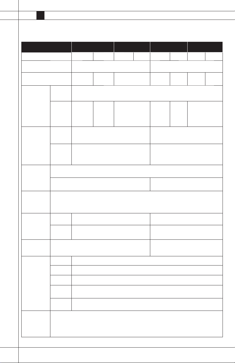
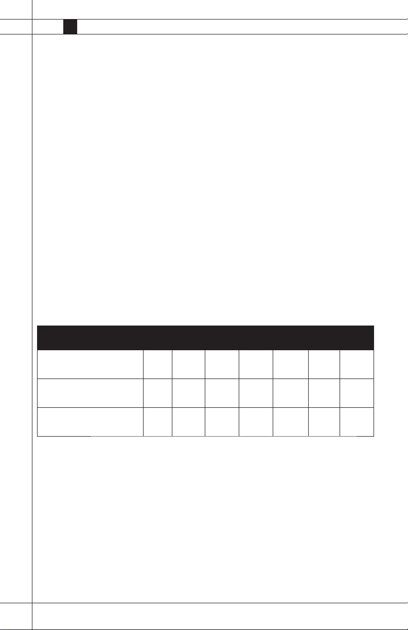
Specifications
TS080 CS080DF TS170 CS170DF
Fuel Type Propane Natural Propane Natural Propane Natural Propane Natural
Maximum Input (Btuh/kW)
Burner Manifold Pressure
(Inches W.C./kPa)
Gas Supply
Pressure
Acceptable at
the Inlet of the
Heater for Purpose of Input
Adjustment
(Inches W.C./
kPa)
Fuel
Consumption/
Hour
MAX.
MIN.
Propane
(lbs./kg)
Natural
Gas
(cu.ft/m3)
10.0/2.49 4.0/1.0 10.0/2.49 10.0/2.49 4.0/1.0 5.4/1.34 5.5/1.37
12.0/2.99 8.0/1.99 11.0/2.74 11.0/2.74 7.0/1.74 11.0/2.74
80,000/23.4 170,000/49.8
13.5 /3.36
3.71 / 1.68 7.88 / 3.5
80 / 2.27 170 / 4.81
Motor
Characteristics
Electrical
Supply
(Volts/Hz/
Phase)
Starting
Amp Draw
Dimensions
(Inches/cm)
LxWxH
Minimum Safe
Distances from
Nearest
Combustible
Materials (feet/
meter)
Minimum
Ambient
Temperature in
Which Heater
May Be Used
Continous
Operation
Top 1 / 0.3
Sides 1 / 0.3
Back 1 / 0.3
Blower
Outlet
Gas
Supply
www.lbwhite.com
Ball Bearing
1/8 H.P. / 93 Watts
1,100 RPM
120/60/1
5.0 7.3
1.5 5.0
29.5 x 13.5 x 20/75 x 34 x 51 30.75 x 18.25 x 28.25/78 x 46.3 x 71.7
6 / 1.83
Propane Gas - U.S: 6/1.83, Canada: 3.05
Natural Gas - N/A
-20°F / -29°C
1/3 H.P. / 248 Watts
1,100 RPM
Owner’s Manual • Premier 80-170
Page 5

General Information
This Owner’s Manual includes accessories commonly
used on this heater. These accessories must be
ordered seperately.
When calling for technical service assistance, or for
other specifi c information, always have model
number, confi guration number and serial number
available. This information is contained on the
dataplate.
This manual will instruct you in the operation and care
of your unit. Have your installer review this manual
with you so that you fully understand the heater and
how it functions.
Contact your local L.B. White distributor or the
L.B. White Company, LLC for assistance, or if you
have any questions about the use of the equipment
or its application.
The L.B. White Company, LLC has a policy of continuous product improvement. It reserves the right to
change specifi cations and design without notice.
Premier Ductable Heaters
5
Owner’s Manual • Premier 80-170
Page 6
6
Premier Ductable Heaters
Safety Precautions
WARNING
■ Do not use this heater for heating human living quarters.
■ Use of direct-fi red heaters in the construction environment can result in exposure to levels of CO,
CO2, and NO2 considered to be hazardous to health and potentially life threatening.
■ Do not use in unventilated areas.
■ Know the signs of CO and CO2 poisoning
- Headaches, stinging eyes.
- Dizziness, disorientation.
- Diffi culty breathing, feeling of being suffocated.
■ Proper ventilation air exchange (OSHA 29 CFR 1926.57) to support combustions and maintain
acceptable air quality shall be provided in accordance with OSHA 29 CFR part 1926.154, ANSI A10.10
Safety Requirements for Temporary and Portable Space Heating Devices and Equipment used in the
Construction Industry or the Natural Gas and Propane Installation Codes CSA B149.1.
- Periodically monitor levels of CO, CO2, and NO2 existing at the construction site – at the
minimum at the start of the shift and after 4 hours.
- Provide ventilation air exchange, either natural or mechanical, as required to maintain
acceptable indoor air quality.
USA 8-Hr. Time weighted average Canada 8-Hr. Time weighted average
(OSHA 29 CFR 1926.55 App A) WorkSafe BC OHS Guidelines Part 5.1
and Ontario Workplaces Reg 833
CO 50 ppm 25 ppm
CO2 5,000 ppm 5,000 ppm
NO2 3 ppm (Reg 833)
USA – Ceiling Limit Canada STEL (15 minutes Reg 833/1 hr.
(Short Term Exposure Limit = 15 minutes) WSBC) WorkSafe BC OHS Guidelines part
5.1 and Ontario Workplaces Reg 833
CO 100 ppm
CO2 15,000 ppm (WSBC)
30,000 ppm (Reg 833)
NO2 5 ppm 1.0 ppm (WorkSafeBC)
5.0 ppm (Reg 833)
■ Ensure that the fl ow of combustion and ventilation air exchange cannot become obstructed.
■ As the building ‘tightens up” during the construction phases, ventilation may need to be increased.
Air Quality Hazard
www.lbwhite.com
Owner’s Manual • Premier 80-170
Page 7

Premier Ductable Heaters
Fuel Gas Odor Odor Fading - No
Propane gas and natural gas have man-made odorants added specifi cally for detection of fuel gas leaks.
If a gas leak occurs, you should be able to smell
the fuel gas . THAT’S YOUR SIGNAL TO GO INTO
IMMEDIATE ACTION!
■ Do not take any action that could ignite the fuel
gas. Do not operate any electrical switches. Do not
pull any power supply or extension cords. Do not
light matches or any other source of fl ame. Do not
use your telephone.
■ Get everyone out of the building and away from the
area immediately.
■ Close all fuel supply valves.
■ Propane gas is heavier than air and may settle in
low areas. When you have reason to suspect a
propane leak, keep out of all low areas.
■ Use your neighbor’s phone and call your fuel gassupplier and your fi re department. Do not re-enter
the building or area.
Odor Detected
■ Some people cannot smell well. Some people
cannot smell the odor of the man-made chemical added to propane or natural gas. You must
determine if you can smell the odorant in these
fuel gases.
■ Learn to recognize the odor of propane gas and
natural gas. Local propane gas dealers and your
local natural gas supplier (utility) will be more than
happy to give you a “scratch and sniff” pamphlet.
Use it to become familiar with the fuel gas odor.
■ Smoking can decrease your ability to smell. Being
around an odor for a period of time can affect your
sensitivity to that particular odor.
■ The odorant in propane gas and natural gas is colorless and the intensity of its odor can fade under
some circumstances.
■ If there is an underground leak, the movement of
gas through the soil can fi lter the odorant.
7
■ Stay out of the building and away from the area
until declared safe by the fi refi ghters and your fuel
gas supplier.
■ FINALLY, let the fuel gas service person and the
fi refi ghters check for escaped gas. Have them
air out the building and area before you return.
Properly trained service people must repair the
leak, check for further leakages, and then relight
the heater for you.
Owner’s Manual • Premier 80-170
■ Propane gas odor may differ in intensity at different
levels. Since propane gas is heavier than air, there
may be more odor at lower levels.
■ Always be sensitive to the slightest gas odor. If you
continue to detect any gas odor, no matter how
small, treat it as a serious leak. Immediately go into
action as discussed previously.
Page 8
8
Premier Ductable Heaters
Attention - Critical
Points to Remember!
■ Propane gas and natural gas have a distinctive
odor. Learn to recognize these odors. (Reference
“Fuel Gas Odor” and “Odor Fading” sections
above.
■ If you have not been properly trained in repair and
service of propane gas and natural gas fueled
heaters, then do not attempt to light the heater,
perform service or repairs, or make any adjustments to the heater on a propane gas or natural
gas fuel system.
■ Even if you are not properly trained in the service
and repair of radiant heaters, ALWAYS be consciously aware of the odors of propane gas and
natural gas.
■ A periodic “sniff test” around the heater or at the
heater’s joints; i.e. hose, connections, etc., is a
good safety practice under any conditions. If you
smell even a small amount of gas, CONTACT
YOUR FUEL GAS SUPPLIER IMMEDIATELY. DO
NOT WAIT!
1. Do not attempt to install, repair, or service this
heater or the gas supply line unless you have
continuing expert training and knowledge of gas
heaters.
QUALIFICATIONS FOR SERVICING AND
a. To be a qualifi ed gas heater service person, you
must have been trained in gas-fi red heater servic-
ing, repair and also have suffi cient experience to
allow you to troubleshoot, replace defective parts,
and test heaters in order to get them into a continuing safe and normal operation condition. You must
completely familiarize yourself with each model
heater by reading and complying with the safety
instructions, labels, owner’s manual, etc. that are
provided with each heater.
b. To be a qualifi ed gas installation person, you must
have suffi cient training and experience to handle
all aspects of installing, repairing, and altering
gas lines, including selecting and installing the
proper equipment, and selecting proper pipe size
to be used. This must be done in accordance with
all local, state and national codes as well as the
www.lbwhite.com
manufacturer’s requirements.
INSTALLATION:
c. In the Commonwealth of Massachusettes, this
product must be installed by a gas fi tter licensed in
the Commonwealth of Massachusettes.
WARNING
ELECTRICAL GROUNDING
INSTRUCTIONS
This heater is equipped with a three prong (grounding) plug for your protection against electrical shock
hazard. It must be plugged into a properly grounded
three prong receptacle. Failure to use a properly
grounded receptacle can result in electrical shock
or death.
2. All installations or applications of L. B. White Co.,
Inc.’s heaters shall meet the requirements of
local, state and national L.P. gas and natural gas,
electrical and safety codes. Your gas supplier,
local licensed electrician, local fi re department
and government agencies can help you determine
these requirements. In the absence of local codes,
comply with the following:
a. Installations in the U.S.A.:
-- NFPA 102, standard for assembly seating, tents
and membrane structures
-- ANSI/NFPA 58, latest edition, Standard for Storage
and Handling of Liquefi ed Petroleum Gas and/or
-- ANSI Z223.1/NFPA 54, National Fuel Gas Code
-- ANSI/NFPA 70, National Electrical Code.
b. Installations in Canada:
-- CAN1-B149.1 or CAN1-B149.2 Installation Codes
-- CSA C22.1 Part 1 Standard Canadian Electrical
Code.
-- CSA C22.2 No.3, Electrical Features of Fuel
Burning Equipment.
3. We cannot anticipate every use which maybe
made of our heaters. Other standards govern the
use of fuel gases and heat producing products
in specifi c applications. Your local authority can
advise you about these. Check with the local
fi re safety authority if you have questions about
applications.
4. Forced air heaters shall not be directed toward any
propane gas container within 20 feet/6.10 meters.
5. Do not wash the heater. Use only compressed air,
a soft brush or dry cloth to clean the interior of the
heater and it’s components.
Owner’s Manual • Premier 80-170
Page 9

Premier Ductable Heaters
9
6. For safety, this heater is equipped with manual
reset high limit switches, an air-proving switch,
and a redundant gas control valve. Never operate
the heater with any safety device that has been
bypassed. Do not operate this heater unless all of
these features are fully functioning.
7. Do not direct the heater toward any propane gas
supply container or gas hose within 20 ft. (6m) of
the heaters hot air discharge.
8. Do not block air intakes or discharge outlets of the
heater. Doing so may cause improper combustion or damage to heater components leading to
property damage.
9. The hose assembly shall be visually inspected on
a daily basis after heater relocation and when the
heater is in use. If it is evident there is excessive
abrasion or wear, or if the hose is cut, it must be
replaced prior to the heater being put into operation. The hose assembly shall be protected from
building materials, and contact with hot surfaces
both during use and while in storage. The replacement hose assembly shall be that specifi ed by the
manufacturer. See parts list.
10. Check for gas leaks and proper function upon
heater installation, when relocating, and after
servicing. Refer to leak check instructions within
installation section of this manual.
15. When the heater is to be stored indoors, the
connection between the propane gas supply
cylinder(s) and the heater must be disconnected
and the cylinder(s) removed form the heater and
stored in accordance with the Standard for the
Storage and Handling of Liquifi ed Petroleum
Gases, ANSI/NFPA 58 or Standard CSA B149.1
Natural Gas and Propane Installation Code as
appropriate.
16. Propane gas supply containers have left handed
threads. Use the manual hand wheel supplied
with the regulator to make a connection of the
regulator’s P.O.L. fi tting into the cylinders’ gas
supply valve.
17. Use pipe joint compound that is resistant to
propane and natural gas.
18. For either indoor or outdoor installation.
Adequate ventilation shall be provided in accordance with OSHA 29 CFR 1926.154, Safety
Requirements for Temporary and Portable Space
Heating Devices and Equipment, ANSI A10.10,
National Fuel Gas Code, ANSI Z223.1/NFPA54,
Liquifi ed Petroleum Gas Code, NFPA 58 or the
Natural Gas and Propane Installation Code,
CAN B149.1, as appropriate.
11. This heater should be inspected for proper
operation by a qualifi ed service person before
each use and at least annually.
12. Always turn off the gas supply to the heater if the
heater is not going to be used in the heating of
the work space.
13. If gas fl ow is interrupted and fl ame goes out, do
not relight the heater until you are that all gas
that may have accummulated has cleared away.
In any event, do not relight the heater for at least
5 minutes.
14. Minimum propane gas cylinder size to be used:
170,000 btuh heaters: (1) 100 lb./45 kg or (2) 40
lb./18 kg. : 80,000 btuh heaters: 40 lb./18 kg
Multiple cylinder installations require a manifold
to ensure continuous supply of gas. The system
must be arranged to provide vapor withdrawal
from the operating cylinder.
Owner’s Manual • Premier 80-170
Page 10
10
Premier Ductable Heaters
General Installation Instructions
WARNING
Can cause property damage, severe injury or death.
1. To avoid dangerous accumulation of fuel gas, turn
off gas supply at the appliance service valve before
starting installation, and perform gas leak test after
completion of installation.
2. Do not force the gas control knob. Use only your
hand to turn the gas control knob. Never use any
tools. If the knob will not operate by hand, the
control should be replaced by a qualifi ed service
technician. Force or attempted repair may result in
fi re or explosion.
1. Read all safety precautions and follow L.B. White
recommendations when installing this heater. If
during the installation or relocating of heater, you
suspect that a part is damaged or defective, call a
qualifi ed service agency for repair or replacement.
INSTALLATION INSTRUCTIONS
2. The heating equipment must be properly positioned before use on a fl at, stable, and horizontal
surface. Ensure the heater is level. (Use a level,
check lengthwise & crosswise). Observe and obey
all minimum safe distances of the heater to the
nearest combustible materials. Safe distances are
given on the heater dataplate and on page 4 of this
manual.
3. L.P Gas Installation Requirements
■ All LP. gas containers must be placed at least
5 feet/1.52 meters from the nearest tent wall
structure.
■ Ensure all L.P. gas containers are secured and protected from all people, vehicular traffi c and contact.
■ L.P. gas containers must be located on a fl at,level,
and stable surface.
■ L.P. gas cylinders (a.k.a. 100 lb/45 kg. cylinders/
tanks) must be secured from tip-over.
Contact your local authorities, L.P. gas dealers, or
fi re marshalls for specifi cs dealing with installation in
your area
4. This heater may be installed either indoors or
outdoors and is approved for use with or without
ductwork. For outdoor installations, additional
accessories are needed to properly provide heated
air to the inside. These accessories are as follows:
www.lbwhite.com
Owner’s Manual • Premier 80-170
Burn Hazard
Only the ducting and the air distribution
accessories as supplied and specifi ed by the
heater’s manufacturer shall be used.
Unit Diff user:
This accessory provides the necessary clearance
to combustible materials and also spreads the
heated air inside the tent. Local codes may require
a 3.04 m separation between the tent and the
heater. In this case the unit mounted diffuser shall
not be used.
Unit Diffuser Part Numbers:
80,000 btu/h heaters: 500-26349
170,000 btu/h heaters: 500-26351
Duct Kit, 12 in./0.3 m. diameter x 12
ft/3.65 m. length:
This accessory provides for locating the heater 10
ft./3,04 meters away from the tent as required by
some local codes.
Use only one duct (12 ft. x 12 in. / 3.65 m x 30.4
cm) per heater with or without an end diffuser.
Duct Kit Part Numbers: Gray 500-26346
White 500-26347 Clear 500-26348
End Diff user:
This accessory is used with the 12 in/.3 m. diameter x 12 ft./3.65 m. duct. It is placed under the tent
edge and provides for spreading of the heated air
inside the tent.
End Diffuser Part Number: 500-26350
DO NOT USE ANY OTHER DUCTWORK, DUCTING,FIELD FABRICATED
DUCTS, TARPS,STOVE PIPE, or any
other means of making the connection
between the heater and the inside of
the tent.
5. When using the unit diffuser or end diffuser air
distribution accessories, ensure the tent material
is laid within the accessory’s channel, and the
tent material is fi rmly anchored to hold the tent
material securely within the channel. See pages
16 and 17 for specifi cs when using these air
distribution accessories.
6. The heater’s gas pressure regulator (with
pressure relief valve) must be protected from
adverse weather conditions (rain, ice, snow) as
well as from building materials (tar, concrete,
Page 11
Premier Ductable Heaters
11
plaster, etc.) which can affect safe operation and
could result in property damage or injury.
7. Insure that all accessories that ship within the
heater have been removed from inside the heater
and installed.
8. Check all connections for gas leaks using approved gas leak detectors. Gas leak testing is
performed as follows:
WARNING
Fire and Explosion Hazard
■ Do not use open fl ame (matches, torches,
candles, etc.) in checking for gas leaks.
■ Use only approved leak detectors.
■ Failure to follow this warning can lead to fi res
or explosions.
■ Fires or explosions can lead to property damage, personal injury or loss of life.
-- Check all pipe connections, hose connections,
fi ttings and adapters upstream of the gas control
with approved gas leak detectors.
-- In the event a gas leak is detected, check the
components involved for cleanliness and proper
application of pipe compound before further
tightening.
-- Tighten the gas connections as necessary to stop
the leak.
-- After all connections are checked and any leaks
are stopped, turn on the main burner.
-- Stand clear while the main burner ignites to
prevent injury caused from hidden leaks that could
cause fl ashback.
-- With the main burner in operation, check all
connections, hose connections, fi ttings and joints
as well as the gas control valve inlet and outlet
connections with approved gas leak detectors.
-- If a leak is detected, check the components
involved for cleanliness in the thread areas and
proper application of pipe compound before
further tightening.
-- Tighten the gas connection as necessary to stop
the leak.
-- Ensure all gas leaks have been identifi ed and
repaired before proceeding.
9. A qualifi ed service agency must check for
proper operating gas pressure upon installation of the heater.
10. Light according to instructions on heater or
within owner’s manual.
11. The heater must have the proper gas
regulator for the application. Use only the
L.B. White regulator originally supplied with
the heater. This regulator includes a POL
fi tting incorporating an excess fl ow valve. The
excess fl ow valve is a safety device which
protects against discharge from the propane
gas supply container if the regulator is broken
off. If the POL fi tting is ever replaced, it needs
to be replaced with an L.B. White POL fi tting.
Failure to do so can result in fi res, explosions,
loss of property, injury or death.
12. A regulator must be connected to the gas
supply so that the pressure to the inlet of
the gas control valve is regulated within the
range specifi ed on the dataplate at all times.
Contact your gas supplier or the L.B.white
Co., if you have any questions.
13. This heater is confi gured for use for propane
gas vapor withdrawal only. Do not use the
heater in an propane gas liquid withdrawal
system or application. If you are in doubt,
contact the L.B. White Co., Inc.
14. The heater must be installed so as not to
interfere with or obstruct normal exits, emergency exits, doors and walkways.
15. Railing, fencing or suitable substitute
materials must be used to keep the heating
equipment from any people using and visiting
the structure.
16. The unit shall be located so that rain, ice,
or snow drainage from the structure does
not affect equipment operation. If the unit is
mounted outside, it must be mounted above
any pooled or standing water. If the unit is
to be located on the ground, a surrounding
trench is recommended to drain any rain, ice
or snow away from the unit.
-- If necessary, replace the parts or components
involved if the leak cannot be stopped.
Owner’s Manual • Premier 80-170
17. The ground and surrounding terrain must be
cleared of any combustible vegetation and
Page 12
12
Premier Ductable Heaters
other combustible materials when the heater is
mounted outside.
18. Eventually, like all electrical/mechanical devices,
the thermostat can fail. Thermostat failure may
result in an underheating condition. The thermostat should be tested to make sure it turns the
heater on and off within a temperature differential
of ±3°F (±1.5 °C).
19. Take time to understand how to operate and
maintain the heater by using this Owner’s
Manual. Make sure you know how to shut off
the gas supply to the building and also to the
individual heater. Contact your fuel gas supplier if
you have any questions.
20. Any defects found in performing any of the
service or maintenance procedures must be
eliminated and defective parts replaced immediately. The heater must be retested by properly
qualifi ed service personnel before placing the
heater back into use.
Propane Gas Supply Sizing
The vaporization of propane is affected by several
factors: the surface area of the container, the liquid
level of propane, temperature surrounding the
container, and the relative humidity. All of these
factors are specifi c to a site. Therefore, a degree of
experience and judgement is required to select the
proper propane supply.
Although experience is the best guide, the following recommendations can be used as a starting
point. The table is based on experience in northern
climates where cold weather and high humidity are
prevalent in the winter. If more or less favorable
conditions prevail at a specifi c site, adjustments can
be made on the basis of experience.
Recommended Propane Gas Supply - Cylinders Required Per Heater
Average Temp º F/ºC 50/10 40/4.4 30/-1.1 20/-6.7 10-12.2 0/-17.8 -10/-23
40 lb.18/kg CS080/TS080 1 1 1 1 2 2 2
100 lb./45 kg CS170/TS170 1 1 1 2 2 2 3
* Cylinders must be manifolded together to allow simultaneous vapor withdrawal from all cylinders.
www.lbwhite.com
Owner’s Manual • Premier 80-170
Page 13
Premier Ductable Heaters
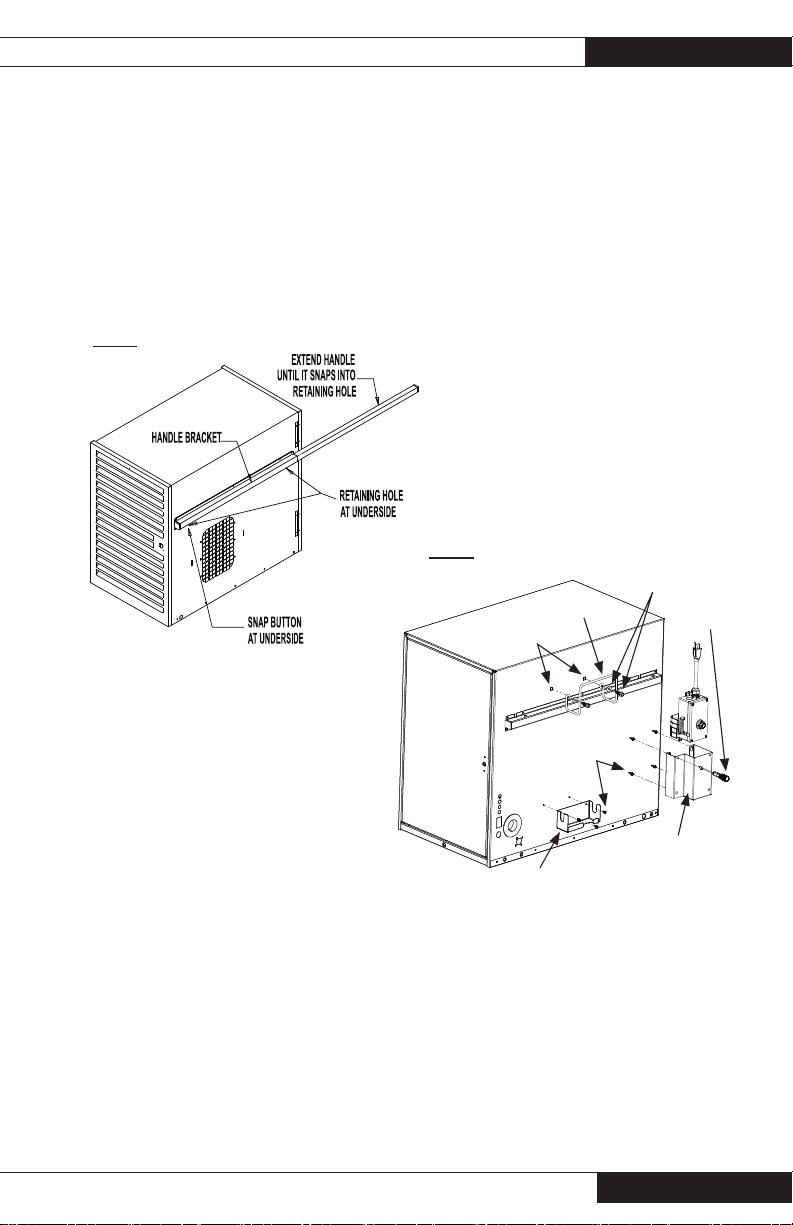
Sliding Handle (Premier 170)
13
The Premier 170 is equipped with sliding handles for
convenient “wheel-barrow” style mobility.
-- Depress the snap-button on the underside of the
sliding handle storage bracket.
-- Fully extend both handles until the snap button
locks into place.
-- For storage, depress the snap button and push
the handles to fully retracted position.
FIG. 1
Hose Hanger,
Regulator Storage
Bracket & Thermostat
Storage Bracket
Assembly
b. Slide the four keyholes of the thermostat
bracket mounting fl anges over the four
screws.
c. After pushing the bracket down to hold into
position, insert a 1/4 in. nut driver or standard
screwdriver through the bracket’s holes
and tighten the screws securely. Store the
thermostat when not in use.
3. Regulator Storage Bracket Assembly (Premier
170) BRACKET
a. Align regulator storage bracket to the two
1/8 in. diameter holes on heater’s lower case
back.
b. Mount the storage bracket to the case using
the two 3/8 in. hex head screws at this point.
Tighten securely.
FIG. 2
Hose Hanger
Cage Nuts
3/8 in.
screws
Bolt and Flat
Washer
Screwdriver
1. Hose Hanger Assembly (all models)
a. Align wire hose hanger to cage nuts on back of
heater.
b. Mount the hanger using the 1/4-20 x 3/4 in.
bolts and 1/4 in. fl at washers. Tighten securely.
See Fig. 2.
2. Thermostat Storage Bracket Assembly (all
models)
a. Thread four 3/8 in. hex head screws into the
four holes at lower corner on back of heater, at
louvered door end. DO NOT TIGHTEN.
See Fig. 2, Premier 170 shown.
Owner’s Manual • Premier 80-170
Regulator
Bracket
Thermostat
Storage
Bracket
Page 14
14
Premier Ductable Heaters
Wheel, Leg & Lifting Handle
Assembly (Premier 170)
See Fig. 3 for assembly of components. Ensure all
hardware is tightened securely.
FIG. 3
1 BOLT 5/16-18 X 1"
AND 1 WASHER 5/16"
AT EACH END
HANDLE - U
WITH 8 1/2" LEGS
AND AXLE HOLE
NUTS 5/16-18
(2 PER SIDE)
SPACER
HUB CAP (PRESS ON)
COTTER
PIN
Leg Assembly (Premier 80)
Assemble the legs to the heater as shown. Tighten
all hardware securely.
REMOVE CASE SCREW AT EACH
END OF HEATER (BOTH SIDES)
BEFORE INSTALLING U-HANDLES.
HANDLE - U, WITH 8" LEGS
WASHER 5/16 (QUANTITY 8)
BOLTS 5/16-18 X 1"
(QUANTITY 10)
INSTALL CAGE NUTS AS SHOWN
BEFORE BOLTING
SUPPORT TO HEATER
FIG. 4
www.lbwhite.com
Owner’s Manual • Premier 80-170
BOLTS 5/16-18 X 1"
(QUANTITY 8)
INSTALL CAGE NUTS AS SHOWN
BEFORE BOLTING
SUPPORT TO HEATER
Page 15
Premier Ductable Heaters
15
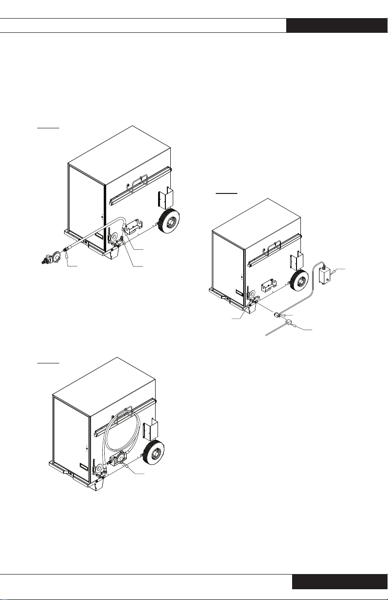
Hose and Regulator
Assembly
1. Connect rigid end of hose to regulator outlet.
Connect other end to hose adapter at heater.
Tighten securely. See Fig 5.
FIG. 5
SWIVEL END
RIGID END
2. The hose may be coiled up and hung on the
hose hanger as shown in Fig. 6.
3. For Premier 170 heaters, store the regulator
in the storage bracket (Fig. 6) when the
regulator is not in use.
ADAPTER
Thermostat Assembly
(All models - kit part
number is 500-09454)
1. Connect male plug on heater into female
side of FIG. 7 series tap plug on thermostat.
See Fig. 7.
2. Plug male side of series tap plug into
grounded, heavy-duty, electrical extension
cord. Plug extension cord into approved
electrical outlet.
FIG. 7
POWER CORD
SERIES TAP PLUG
HEAVY DUTY
EXTENSION CORD
WITH GROUND
THERMOSTAT
FIG. 6
REGULATOR IN
BRACKET
Owner’s Manual • Premier 80-170
Page 16

16
Premier Ductable Heaters
Duct Kit Assembly
Accessory 500-26346 - Gray &
500-26347 - White (Not included)
1. See Fig. 8 for installation of duct. Hand
tighten the screws snugly. (Note: Slots are
also provided at the sides of heater’s air
discharge to accomodate earlier style duct
adapters with tab mounting confi guration.)
2. Extend duct kit to 12 ft./3.65 m. length.
FIG. 8
3. Position duct as shown. Eliminate any kinks
in duct.
FIG. 8
FASTEN WING SCREWS
INTO CAGE NUTS AT
BLOWER OUTLET AND
TIGHTEN
SLOTS FOR INSTALLING
EARLIER STYLE DUCTING
www.lbwhite.com
Owner’s Manual • Premier 80-170
INSTALL TAB AT BOTTOM OF COLLAR
INTO SLOT AT BOTTOM OF OUTLET
BEFORE FASTENING WING SCREWS
EARLIER STYLE DUCTING
10 FT
CLEARANCE
SIDE WALL
Page 17

Premier Ductable Heaters
Unit Diffuser
Accessory 500-26349 (Premier 80) &
500-26351 (Premier 170) (Not included)
1. See Fig. 9 for installation of unit diffuser.
Hand tighten FIG. 9 the screws snugly. (Note:
Slots are provided to accomodate earlier
style unit diffusers with tab mounting.)
2. Position the diffuser under the tent wall
as shown. Lay the tent material within the
channel of the diffuser. Ensure the material
is securely anchored within the channel to
prevent contact with the heater. See below
for typical installation.
FIG. 9
CAGE NUTS
WING SCREW
17
SIDE WALL
MATERIAL LOCATED IN CHANNEL
AND SECURELY ANCHORED TO
PREVENT CONTACT WITH HEATER
Owner’s Manual • Premier 80-170
Page 18

18
Premier Ductable Heaters
End Diffuser
Accessory 500-26350
(Not included)
1. Wrap the duct clamp around duct and collar.
Saddle of clamp lays over duct coil. Connect
clamp ends together and tighten securely.
See Fig. 10.
FIG. 10
SLOT
WING SCREW
INSERT TAB AT BOTTOM OF COLLAR
INTO SLOT BEFORE TIGHTENING
WING SCREWS INTO CAGE NUTS.
CAGE NUT
2. Position the diffuser under the tent wall
as shown. Lay the tent material within the
channel of the diffuser. Ensure the material is
securely anchored within the channel.
See Fig. 11.
FIG. 11
www.lbwhite.com
Owner’s Manual • Premier 80-170
Page 19

Premier Ductable Heaters
19
Connecting the
Regulator to the
Gas Supply
■ Only use the L.B. White regulator supplied with
the heater.
■ Use pipe joint compound that is resistant to
propane and natural gas at all threaded connections
■ The heater must be regulated at all times for
proper operation.
■ Leak check all regulator connections after connecting to the gas supply.
Standard Premier Propane Gas
Heaters (Models TS080/170)
1. Remove the cap from the POL fi tting on the
regulator. (Do not discard the cap)
2. Insert the POL stem into the cylinder valve.
Push the spring loaded hand wheel up against
the threaded nut. Turning counter clockwise,
thread the POL nut into into the container valve
using the hand wheel. Firmly tighten. See Fig.
12.
FIG. 12
Standard Premier Natural Gas Heaters
(Models TS080/170)
--- Use the regulator shipped with the natural gas heater
if the supply pressure to the heater is above the
maximum inlet pressure of 13.5 In.W.C./3.36 kPA, as
stated on the heater’s data plate and in this owner’s
manual.
--- The natural gas regulator supplied with the heater
requires a minimum 2 PSIG inlet pressure.
--- Connect the natural gas regulator (part # 09795) to
the natural gas supply line, using the proper connections.
Dual Fuel Premier Heaters (Models CS080/
CS170)
■ The regulator provided with dual fuel heaters is suit-
able for both propane or natural gas
■ Only use the L.B. White regulator supplied with the
heater.
■ Use pipe joint compound that is resistant to propane
and natural gas at all threaded connections
■ The heater must be regulated at all times for proper
operation.
■ Leak check all regulator connections after connecting
to the gas supply.
POL Fitting
Hand Wheel
3. Slowly open the cylinder valve. This will
prevent lock-up of the excess fl ow valve built
within POL stem.
4. When storing or transporting the heater, use
the protective cap to ensure the POL fi tting is
protected from damage and water entry.
Owner’s Manual • Premier 80-170
When using propane gas as the fuel:
1. Thread the bushing into the regulator inlet. Tighten
securely. See Fig. 13.
FIG. 13
Bushing
Page 20

20
Premier Ductable Heaters
2. Remove the plastic cap from the POL fi tting. (POL fi t-
ting is located in hardware bag. Do not discard the cap)
3. Slide the spring over the POL stem. Smaller diameter
end of spring is toward brass nut of POL. See Fig. 14.
Slide the open side of the hand wheel over the POL
stem. Thread the assembly into the 1/4 in. inlet of the
bushing installed in the regulator. Tighten securely
using a wrench at the fl ats of the POL stem See Figs.
14 and 15.
FIG. 14
Spring (Smaller Diameter)
Flats
FIG. 15
FIG. 16
Hand Wheel
5. Slowly open the cylinder valve. This will
prevent lock-up of the excess fl ow valve built
within POL stem.
6. When storing or transporting the heater, use
the protective cap to ensure the POL fi tting is
protected from damage and water entry.
When using natural gas as the fuel:
--- The regulator supplied with the dual fuel
heater is required for use with natural gas if
the natural gas supply pressure to the heater
is above the maximum inlet pressure of 13.5
in.W.C./3.36 kPA, as stated on the heater’s
data plate and in this owner’s manual.
4. Insert the POL stem into the cylinder valve. Push the
spring loaded hand wheel up against the threaded nut.
Turning counter clockwise, thread the POL nut into
into the container valve using the hand wheel. Firmly
tighten. See Fig. 16.
www.lbwhite.com
Owner’s Manual • Premier 80-170
--- The regulator requires a minimum natural gas
supply pressure of 2 PSIG.
--- Remove the POL fi tting assembly with hand-
wheel from the regulator inlet.
--- Connect the regulator to the natural gas supply
line using the proper connections.
Page 21

Start-Up Instructions
Premier Ductable Heaters
21
1. Connect the electrical cord to an approved
electrical outlet.
A selector switch located on the back of the
heater allows operation in either heating or
ventilation (no heat) modes. See Fig. 17.
FIG. 17
Selector
Switch
A. Heat Mode Operation
a. Open all manual fuel supply valves. Check
for gas leaks using an approved leak detector. The gas control valve in the heater
has a manual shut-off feature incorporated
into the valve assembly. Ensure the indicator on the valve is positioned to ON. See
Fig 18.
b. Push the selector switch to heat.
See. Fig. 17.
c. Set the thermostat above room
temperature
-- The fan motor will start
-- Igniter will spark
-- Ignition occurs
d. The thermostat cycles the heater on and off
based on set point.
(It is normal for air to be trapped in the gas hose on
new installations. The heater may attempt more than
one trial for ignition before air is fi nally purged from
line and ignition takes place.)
When the switch is set to heat, four status lights
(see Fig.17) will be activated in sequence as specifi c
circuits are checked by the ignition control. If the
heater does not light, and a status light is off, refer to
the troubleshooting label on the inside of the heater’s
burner end access door or the troubelshooting of the
manual.
B. Vent Mode Operation
-- Push the selector switch to off, O, then to vent
-- Only the fan motor will operate. The igniter will
not spark,nor will ignition occur.
The ventilation feature is used when air circulation is
required. The heater will not cycle on its thermostat
setting.
C. Off O
1. Position the switch to midpoint O.
FIG. 18
2. Do not exceed input rating stamped on
nameplate or manufacturer’s recommended burner orifi ce pressure for
size orifi ce(s) used. Make certain that
the primary air supply to main burner
is open and free of dust, dirt and debris
for complete, proper combustion.
Owner’s Manual • Premier 80-170
Page 22

22
Premier Ductable Heaters
Shut-Down Instructions
For normal shut-down, set the thermostat below
room temperature. When servicing or performing
maintenance, follow steps 1 - 5.
1. Close the fuel supply valve.
2. Allow the heater to burn off any fuel gas remaining
in the gas supply line.
3. Set the thermostat to “Off” or “No Heat”.
4. Position selector switch to O (off).
5. Disconnect the heater from its gas and electrical
supplies.
Gas Selector Valve
Dual Fuel (DF) Heaters
Only
This heater is shipped from the factory with the
fuel selector valve in the propane gas (LP)
position. Ensure the fuel selector valve’s handle
is properly positioned for the fuel being used.
1. This feature allows the heater to operate on either
propane or natural gas without changing out the
burner orifi ce. The gas selector valve is located
between the gas control valve and the burner. Gas
selection is made by sliding the locking sleeve (if
provided) up and repositioning the valve’s handle.
THIS IS NOT A MANUAL GAS SHUT OFF VALVE.
FIG. 20
Handle Position
Propane Gas
3. The handle must be fully set at 90 degrees to gas
fl ow (propane gas) or parallel to gas fl ow (natural
gas) for proper operation. Also refer to the decal
located on the heater’s base, adjacent to the
selector valve.
Do not operate the heater with the selector valve
handle set between either postion, otherwise improper operation will occur.
4. Premier 170 DF: The valve’s handle can be locked
to prevent improper positioning. Use the hole
provided. See Fig. 21.
FIG. 21
2. Refer to Figs. 19 and 20. The valve handle must
be properly positioned for the specifi c gas being
used (Premier 170 DF shown. Same handle positions for Premier 80 DF).
FIG. 19
Locking Sleeve (on Premier 170DF) Slide up to
reposition valve handle
Handle Position
Natural Gas
www.lbwhite.com
Owner’s Manual • Premier 80-170
Page 23

Cleaning Instructions
Premier Ductable Heaters
23
WARNING
Fire, Burn, and Explosion Hazard
■ This heater contains electrical and mechanical
components in the gas management, safety
and airfl ow systems.
■ Such components may become inoperative or
fail due to dust, dirt, wear, aging, or the corrosive atmosphere of an animal confi nement
building.
■ Periodic cleaning and inspection as well as
proper maintenance are essential to avoid
serious injury or property damage.
1. Before cleaning, shut off all gas supply valves
and disconnect the electrical supply.
2. The heater should have dirt or dust removed
periodically:
a. Before each use give the heater a general
cleaning using compressed air or a soft
brush or dry rag on its case and internal
components. At this time, dust off the motor
case to prevent the motor from over-heating.
b. At least once a year, give the heater a thor-
ough cleaning. At this time, remove the fan
and motor assembly and brush or blow off
the fan blade assembly. Additionally, make
sure the burner air inlet venturi ports and
the casting are free of dust accumulation.
WARNING
Do not use a pressure washer, water, or liquid
cleaning solution on any gas controls. Use of a
pressure washer, water, or liquid cleaning solution on the control components can cause severe
personal injury or property damage due to water
and/or liquids:
■ In electrical components, and wires causing
electrical shock or equipment failure.
■ On gas control valves causing corrosion which
can result in gas leaks and fi re or explosion
from the leak.
Clean all components of the heater with
pressurized air, a dry brush, or a dry cloth.
Owner’s Manual • Premier 80-170
Page 24

24
Premier Ductable Heaters
Maintenance Instructions
BEFORE EACH USE:
■ Check the area surrounding the heater to
ensure it is clear and free of combustible materials, gasoline, and other fl ammable vapors
and liquids.
■ Have your gas supplier check all gas connections for leaks or restrictions in gas lines.
■ Inspect the regulator vent to make sure the
regulator vent is not blocked. Debris, insects,
insect nests, snow, or ice on a regulator can
block vents and cause excess pressure at the
heater.
■ Check all wiring, associated terminals, and
electrical components within the heater for
corrosion, frayed or cut insulation, tight connections, etc. Repair or replace as necessary.
■ Check the hose assembly after heater
installation, relocation, and when the heater
is in use. If it is evident there is excessive
abrasion or wear, or if the hose is cut, it must
be replaced prior to the heater being put back
into operation
■ Review all heater markings (i.e. wiring diagram, warnings, start-up, shut-down, troubleshooting, etc.) at the time of maintenance
for legibility. Make sure none are cut, torn, or
otherwise damaged. Any damaged markings
must be replaced immediately by contacting
the L.B. White Co., Inc. Data plate, startup
and shut-down instructions and warnings are
available at no cost.
ANNUALLY:
■ Clean and check the igniter for cracks. Replace
if necessary.
■ Regulators can wear out and function improperly.
Have your gas supplier check the date codes
on all regulators installed and check delivery
pressures to the heater to make sure that the
regulator is reliable.
■ Test both manual reset high limit heat switches
to ensure proper operation. (See Testing instructions for same in this owner’s manual.)
www.lbwhite.com
Owner’s Manual • Premier 80-170
Page 25

Service Instructions
WARNING
Burn Hazard
■ Heater surfaces are hot for a period of time after
the heater has been shut down.
■ Allow the heater to cool before performing
service, maintenance, or cleaning.
■ Failure to follow this warning will result in burns
causing injury.
WARNING
Fire and Explosion Hazard
■ Do not disassemble or attempt to repair any
heater components or gas train components
such as gas valves, or gas hoses.
■ All component parts must be replaced if defects
are found.
Premier Ductable Heaters
4. The air proving switch must not be jumpered. If
jumpered, the ignition control will not allow heater
operation. Test the air proving switch for continuity. If defective, replace the switch.
5. Open the respective case panel for access to
burner or fan related components. Open the
control box for access to the ignition controller,
and transformer.
6. Disconnect the appropriate electrical leads when
replacing components.
7. For reassembly, reverse the respective service
procedure. Ensure gas connections are tightened
securely and leak checked.
8. After servicing, start the heater to ensure proper
operation.
25
■ Failure to follow this warning will result in fi re or
explosions, causing property damage, injury, or
death.
1. Close the fuel supply valve to the heater
and disconnect the electrical supply before
servicing unless necessary for your service
procedure.
2. Clean the heater’s orifi ce with compressed
air or a soft, dry rag. Do not use fi les, drills,
broaches, etc. to clean the orifi ce hole.
Doing so will enlarge the hole, causing
combustion or ignition problems. Replace
the orifi ce if it cannot be cleaned properly.
3. The high limit switch can be tested by:
-- Disconnecting the leads at the compo-
nent, and jumpering the leads together.:
-- Reconnect the electrical supply and open
fuel supply valves.
-- If the heater lights, the component is
defective and must be replaced.
-- Do not leave the jumper on or operate the
heater if the part is defective. Replace the
part immediately.
-- An alternate method for checking the
components is to perform a continuity
check.
Motor & Fan Assembly
1. Open louvered access panel opposite the
burner end of heater. Disconnect motor leads.
2. Remove all screws securing the motor mounting
plate to the housing.
3. Pull the fan and motor assembly from the
housing.
4. Loosen set screws on fan wheel.
5. Pull the fan wheel from motor shaft.
6. Remove the four nuts securing motor to
mounting plate.
FIG. 22
Motor Mount Plate
Screws
Owner’s Manual • Premier 80-170
Page 26

26
Premier Ductable Heaters
FIG. 23
MOTOR MOUNT PLATE
FAN WHEEL
Igniter and Flame
Sensor Assembly
The igniter is of local sense design, meaning it
also serves to sense burner fl ame.
1. See Fig. 25 for location of igniter/sensor
assembly.
2. Remove the two screws securing the
mounting bracket to the burner. Remove
igniter assembly.
MOTOR
CLEARANCE
Premier 80 3/16 IN/4.7 mm
Premier 170 1/8 IN./3.2 mm
Air Proving Switch
The air proving switch is located on the fan housing at
the motor end of the heater. It must work properly to
allow an ignition cycle. If the air proving switch contacts
are closed before the ignition control starts the fan motor, or do not close on a call for heat after the fan motor
starts, ignition will not occur . See Fig. 24.
To service:
-- Remove the two (2) sheet metal screws holding the
switch with bracket to blower housing.
-- Remove the assembly by turning the switch so the
paddle on the switch arm can be pulled through the
oblong hole on side of fan housing.
FIG. 24
3. Disconnect high voltage cable from igniter
assembly.
4. Remove the two screws that secure the
igniter sensor to the mounting bracket.
• The igniter and ground rod should be
cleaned to maintain proper ignition.
-- Use steel wool or emery cloth.
-- Rub briskly to remove buildup of dust,
dirt, and oxide.
• Check the igniter’s ceramic base for cracks.
-- Replace the igniter if cracks are found.
FIG. 25
Same specifi cations for all versions -
Premier 170 shown
FRONT VIEW
1/2 IN. DISTANCE FROM IGNITER
TOP TO BURNER TIP
HIGH VOLTAGE IGNITION LEAD
MOUNTING BRACKET
IGNITER BRACKET
MOUNTING SCREWS
IGNITER/SENSOR MOUNTING SCREWS
www.lbwhite.com
Owner’s Manual • Premier 80-170
TOPVIEW
ELECTRODE GAP IS 1/8" &
CENTERED OVER BURNER PORT
BURNER PORT
Page 27

Manual Reset High Limit
Switches
WARNING
Fire Hazard
■ Do not operate the heater with the high limit
switch bypassed.
■ Operating the heater bypassed high limit switch
may lead to overheating, possibly resulting in a
fi re, with subsequent damage to the heater or
property damage.
This heater has two limit switches: one inside the solid
door end on the heat chamber, the other inside the
louvered door end mounted on the fan housing side
panel. Both are easily identifi ed by a red reset button in
the center of the switch. See Figs. 26 and 27, Premier
170 shown.
FIG. 26
Burner end high limit
Premier Ductable Heaters
Function
If the heater overheats, one or both of the limit switches
can trip, opening the electrcial circuit to the gas control
valve. Overheating is generally caused by duct restrictions, low voltage, blocking the heater’s air inlet, or excessive gas pressure.
Resetting
If either trips, remove the red cap and fi rmly press the
reset button in the middle of the switch. Then, shut the
heater off and turn it back on. Determine the cause of the
limit tripping.
Testing
To ensure proper function of these critcal safety components, both switches should be tested annually, typically
when the heater is given a thorough cleaning.
1. Remove either high limit switch.
2. Holding the switch by one of its mounting legs, apply
a small, soft fl ame only to the sensing portion on the
back of the switch. See Fig. 28. Be careful not to melt
the plastic housing of the switch when conducting this
test.
27
FIG. 27
Fan end
high limit
3. Within a minute, you should hear a click coming from
the switch, indicating the contacts of the switch have
opened.
4. Allow the switch cool down for about a minute. Remove
the red cap and fi rmly press the reset button on the
switch.
5. Check for electrical continuity across the switch terminals to make sure the contacts have closed. Install
the red cap.
FIG. 28
RESET BUTTON
TERMINAL
MOUNTING
LEG
Owner’s Manual • Premier 80-170
SENSING
SURFACE
FLAME
Page 28

28
Premier Ductable Heaters
Burner Orifice & Gas
Control Valve
1. Remove the gas hose from heater
2. Remove the elbow and all screws at inlet of gas control
valve. See Fig. 29.
FIG. 29
3. Open the solid door at the gas inlet end of the heater.
4. Remove the burner retaining bolt at the underside of
the heaters base. For Premier 170 heaters, the bolt is
accessible through an opening in the heater’s support
leg. Use a ratchet with extension and 9/16 in. socket.
See Fig. 30.
FIG. 30
5. Lift and pivot the gas control assembly to
expose the burner orifi ce. See Fig. 31. Replace
components as needed.
FIG. 31
6. When assembling the control valve to manifold,
the valve must be offset 8 degrees from the
orifi ce holder to ensure the control valve aligns
to its mounting holes. See Fig. 32.
FIG. 32
Premier 80
Orifi ce Holder
www.lbwhite.com
Owner’s Manual • Premier 80-170
Bolt
Gas Control
8°
Page 29

Premier Ductable Heaters
29
Premier 170
ORIFICE
HOLDER
8°
Ignition control
The control sends and receives voltages to operate or
verify operation of components. Refer to the following
and Fig. 33 to understand the ignition control’s terminal
designators if doing voltage checks on the control.
L1: Main power supply voltage to control.
IND: Main power supply voltage from control to motor.
LED: Not used
MV: 24 VAC from ignition control through both high
limit switches to gas control valve.
PS2: 24 VAC return from air proving switch back to
ignition control.
PS1: 24 VAC from ignition control to air proving
switch.
W: 24 VAC from transformer to igntion control. (without
this voltage from the transformer, the ignition
control will not function.
FS: No terminal.
R: No terminal.
X: No terminal
C/COM: Earth ground for transformer and ignition
control.
FIG. 33
GAS
CONTROL
Transformer
The transformer reduces main power supply voltage
to 24 VAC for operation of the the ignition control.
Without 24 VAC from the transformer, the ignition
control will not function, nor will the heater operate.
See Fig. 34 for location of the transformer, Premier
170 shown.
FIG. 34
Burner Casting
Also refer to “Operation Sequence” within this manual
as needed to understand operation of the ignition
control during a call for heat.
Owner’s Manual • Premier 80-170
Tra nsf orm er
Page 30

30
Premier Ductable Heaters
Gas Pressure Checks
WARNING
■ Do not disassemble the gas control valve.
■ Do not attempt to replace any components of
the gas control valve.
■ The gas control valve must be replaced if any
physical damage occurs to the control valve
assembly.
■ Failure to follow this warning will result in fi re
or explosions, leading to injury or death to
humans, and property damage.
■ The following explains a typical procedure to
be followed in checking gas pressures.
■ The gas pressures will vary depending upon
fuel type.
■ Consult the dataplate on the heater or page
4 in this manual for specifi c pressures to be
used in conjunction with this procedure.
■ Gas pressure measured at the inlet to the
gas valve is Inlet Pressure and gas pressure
measured at the outlet of the gas valve is
Burner Manifold Pressure.
A. Preparation
1. Obtain two pressure gauges capable of
reading up to 35 in. W.C.
2. Disconnect the heater from the electrical
supply and close the fuel supply valve to the
heater inlet.
3. Open the burner access panel.
4. Brush or blow off any dust and dirt on or in
the vicinity of the gas control valve.
FIG. 35
ON
OFF
INLET PRESSURE TAP
2. Securely connect a pressure gauge to each
pressure tap.
3. Open the fuel supply valves to the heater and
reconnect the heater electrical supply.
4. Start the heater
C. Reading Pressures
1. With the heater operating, the pressure
gauges should read the pressures specifi ed
on the dataplate .
2. Do the readings at the inlet and outlet pressure gauges agree with that specifi ed on the
dataplate? If so, then no further checking or
adjustment is required. Proceed to section D.
3. If the inlet pressures do not agree with that
specifi ed on the dataplate, then the regulator
controlling gas pressure to the heater requires
adjustment.
4. If the inlet pressures are correct and the
burner manifold pressure does not agree with
that specifed on the dataplate, then the gas
control valve’s internal pressure regulator
requires adjustment. See Fig. 36 for regulator
location.
OUTLET PRESSURE TAP
B. Gauge Installation
1. Locate the inlet and outlet pressure taps,
see Fig. 35. Remove the pressure tap plug
using a 3/16 in. allen key.
www.lbwhite.com
Owner’s Manual • Premier 80-170
Page 31

Premier Ductable Heaters
31
FIG. 36
INTERNAL PRESSURE REGULATOR
LOW PRESSURE GUAGE
OUTLET PRESSURE TAP
ON
OFF
INLET PRESSURE TAP
EXAMPLE SHOWS PRESSURE FOR L.P. GAS
D. Completion
1. Once the proper inlet and burner manifold
pressures have been confi rmed and/or
properly set, close the fuel supply valve to the
heater and allow the heater to burn off any gas
remaining in the gas supply line.
2. Disconnect the heater from its electrical
supply.
3. Remove the gauges and connecting hoses.
4. Install pressure tap plugs and tighten securely.
Check for gas leaks.
LOW PRESSURE GUAGE
Owner’s Manual • Premier 80-170
Page 32

32
Premier Ductable Heaters
Troubleshooting Guide
READ THIS ENTIRE SECTION
BEFORE BEGINNING TO
TROUBLESHOOT PROBLEMS.
WARNING
■ This heater can start at any time.
■ Troubleshooting this system may require
operating the unit with line voltage present and
gas on. Use extreme caution when working on
the heater.
■ Failure to follow this warning may result in
property damage, personal injury or death.
The following troubleshooting guide provides
systematic procedures for isolating equipment
problems. This guide is intended for use by a
QUALIFIED GAS HEATER SERVICE PERSON.
DO NOT ATTEMPT TO SERVICE
THESE HEATERS UNLESS YOU
HAVE BEEN PROPERLY TRAINED.
TEST EQUIPMENT REQUIRED
The following pieces of test equipment will be
required to troubleshoot this system with minimal
time and effort.
• Digital Multimeter - for measuring AC and DC
voltage and resistance.
• Low Pressure Gauge - for checking inlet and
outlet pressures at the gas control valve against
dataplate rating.
■ Visually inspect equipment for apparent
damage.
■ Check all wiring for loose connections and
worn insulation.
Refer to the system operation sequence in this
section to gain an understanding as to how the
heater operates during a call for heat. Understanding the sequence of operation is important
as it relates to problem solving.
Four green lights are located next to the selector
switch. Each light will be acitvated in sequence
as that circuit within the heater is verifi ed by the
ignition control. If the circuit is not verifi ed, that
respective light will not be activated. The most
www.lbwhite.com
common heating mode problems are identifi ed
by a green light being OFF if a specifi c fault occurs.
However, two other problems may also occur. See the
following.
Identify the specifi c problem and then refer to the
appropriate troubleshooting fl ow chart.
Heating Mode Problems Page
Power status light not on .................................... 34
Transformer status light not on ........................... 34
Air proving status light not on ............................. 35
Gas control status light not on ............................ 36
All lights are on, fan motor runs,
burner does not light ........................................... 37
All lights are on, EXCEPT gas valve light.
Fan motor does not run, burner does not light. .. 38
Heater lights but does not stay lit ....................... 38
Ventilation Mode Problem Page
Motor Does Not Run ........................................... 38
Components should be replaced only after each step
has been completed and replacement is suggested in
the fl ow chart. Refer to the Servicing sections as neces-
sary to obtain information on disassembly and replacement procedures of the component once the problem is
identifi ed by the fl ow chart.
DIRECT IGNITION OPERATION
SEQUENCE:
• The thermostat calls for heat.
- Power light acitvated indicating heater is receiving
its main power supply.
• Line voltage is sent to selector switch.
• Selector switch sends line voltage to the transformer
and to ignition control.
• Transformer reduces line voltage to 24 volts which is
sent to ignition control.
- Transformer light is activated indicating that ignition
control is receiving 24 volts from transformer.
• Ignition control module performs self safety check.
• Fan motor starts.
• Ignition control module sends 24 volts to air
proving switch.
- Internal components are tested.
- Air proving circuit is checked and proven.
• Ignition control module begins ignition trial sequence.
Owner’s Manual • Premier 80-170
Page 33

• Air proving switch closes and 24 volts are returned
to the ignition control module.
- Air proving switch light is activated indicating
that the air proving circuit is operating properly.
• Ignition control module sends high voltage to the
igniter electrode.
- Igniter sparks.
• Ignition control module sends 24 volts to the gas
control valve through the high limit switches.
- Gas valve light is activated indicating that gas
control valve is receiving 24 volts.
- Gas control valve opens. - Ignition occurs.
• Igniter continues to spark until fl ame
proving occurs.
- Ignition spark is cut off.
- Gas valve stays open.
• Room warms to desired temperature.
- Thermostat is satisfi ed.
- Heater shuts down.
• Process starts again on a call for heat.
IGNITION FAILURE SEQUENCE:
• There are three ignition trials. Each trial takes 10
seconds.
• If burner fl ame is not maintained at the end of the
third trial, the module goes into safety lockout
- Gas valve closes.
- Ignition spark shuts off.
- Fan motor stops.
• To retry for ignition, the systems must
be reset:
- Turn the thermostat down and then up to call
for heat or unplug heater and plug it back in or
- Position selector switch to off and then back to
on.
Premier Ductable Heaters
33
Owner’s Manual • Premier 80-170
Page 34

34
Premier Ductable Heaters
Replace
thermostat
Replace
power co rd.
Yes
continutity?
Is thermostat
defect ive? Check
continuity.
defect ive? Check
Is heater p ower cord
Yes Ye s
Check el ectrical wir ing and connec tions to
light. Ensure 24 volt s is supplied to lig ht. If
thermostat?
Check electrical
connections. If good
replac e LED
Is power delivere d to
wiring.
connec tions and
Check all electrical
24 volts is su pplied, replac e light.
Yes
No
Is trans former
ignition control?
to termi nal W on
Is main power
supplied to LED?
Yes
room temperature?
Is thermostat s et above
Yes Yes
No
Is main power
on ignition control?
supplied to term inal LI
closed?
Is circu it breaker
room temperature
Set ther mostat above
No No No No
Reset breaker.
breaker tripping.
Determ ine cause of
deliver ing 24 volts
Yes Yes
No
voltage?
Is trans former
receiving main
replace transformer.
Check wiring and electrical connec-
tions. I f electrical c onnections are good,
connections
Check wiring and electrical
Power status
light not on
All lights are ONHEATING MODE: Normal operation
www.lbwhite.com
Owner’s Manual • Premier 80-170
Tra nsf orm er
status light is
not on.
Page 35

Premier Ductable Heaters
Verify 24 vo lts are
receiv ed at the indicato r
light. If so, repla ce light.
35
Check air proving
switch f or continuity.
Replac e switch.
Yes
No
on controller?
from air p roving
Are 24 volt s returned
switch to termin al PS2
Tighten t he fan
set screw(s)
Yes
Is fan bin ding? Repair or replace
Yes
Yes
No
Are wir ing and
Yes Yes
No
motor shaft?
Is fan loo se on
Replace
fan motor.
No
tions good?
electrical connec-
Yes
Yes
No
Are 24 volt s
Repair or r eplace
starts?
termin al PS1 on
receiv ed at the air
proving s witch from
controller when motor
as needed.
tions good?
Are wires and
electrical connec-
Yes
No
switch good?
from air p roving
trical connections
Are wires and ele c-
No
tions.
wires or c onnec-
Repair or r eplace
as needed.
Repair or r eplace
wires or c onnections
No
Does fan
motor start?
Air proving
status light is
not on.
Does ignition
voltag e to motor
control send proper
No
on control?
from ter minal IND
control.
contro l. Replace
Defect ive ignition
Owner’s Manual • Premier 80-170
Page 36

36
Premier Ductable Heaters
No
to gas con trol?
Is high limit at burner
end delivering 24 vo lts
No
volts?
end rece iving 24
Is high limit at burner
end?
high limit at burner
deliver ing 24 volts to
Is high limit at fan en d
Yes Yes Ye s
ignition control?
Is high limit at fan en d
receiv ing 24 volts from
Yes
reset th e switch. Check
of high lim it opening. Chec k
continuity. Determine cause
If high limit switc h is tripped,
needed.
Defect ive wire or
Repair or r eplace as
termin al connection.
depres s the swtich res et button.
If high limit switc h is tripped, fi rmly
high limit opening. Check for prop er
Check continui ty. Determine ca use of
No No
needed.
Defect ive wire or
Repair or r eplace as
termin al connection.
in ducting.
blockages at air inlet or
for prop er gas pressure
warm air dischar ge, kinks
FOR FUEL USED
TO CORREC T POSITION
ing. FOR DU AL FUEL HEATERS:
gas pressure, blockages at air inlet
or warm ai r discharge, kinks in duct-
ENSURE SELECTOR VALVE IS SET
Defective light,
replac e the light.
24 volts?
Is light re ceiving
Yes Yes
Defect ive wire
needed.
or repla ce as
nection. Repair
or terminal con-
No
control?
Is ignit ion control
sending o ut 24 volts
from ter minal MV on
Gas control
status light is
not on.
www.lbwhite.com
Owner’s Manual • Premier 80-170
No No
Replace control.
Defect ive ignition co ntrol.
24 volts?
Is gas control
valve rec eiving
Defect ive wire
needed.
and repl ace as
nection. Repair
or terminal con-
Page 37

Premier Ductable Heaters
Plugged burner or
these components.
burner orifi ce. C lean
No
high voltage?
Is ignition con-
trol sen ding out
pressure?
valve set to
proper outlet
Is gas control
pressu re. Refer to heater ’s dataplate.
Replac e control valve.
A. Check outle t pressure. provide prop er outlet
B. If no pr essure, the cont rol valve is defec tive.
No No
sure?
supply pres-
Is gas control
valve rec eiving
proper i nlet gas
No
position?
Is gas control
valve set to O N
heater’s dateplate
pressu re. Refer to
Provide p roper inlet
Check in let pressure.
valve to ON .
Set the co ntrol
Yes YesYesYes
Is ignition
connec ted to
lead securely
igniti on control
properly
Is igniter
gapped?
Determ ine if ignition c ontrol is sending high voltage:
No
and igniter?
No
igniti on terminal on co ntrol
- Close t he heater’s f uel sup ply val ve.
- Remove ignition l ead from igniti on control
- Hold a sc rewdriver tip ab out 1/8 to 3/16 in. from m ale
- Turn heater on
- Spark sh ould be seen. If none, repla ce ignition co ntrol.
components.
Ensure le ad is
connec ted at both
Check ig niter
specifi cations.
gap and re gap to
Replace igniter.
37
Yes Yes Yes Yes
No
spark?
Does ign iter
Yes
No
valve ope n?
Is fuel su pply
All lights are on,
Fan motor runs
but bur ner do es
valves to heater
Open fuel supply
not light.
Is igniter high
No
connected?
voltag e lead
voltage lead
Connec t high
cracked?
Is igniter insula tor
Yes Yes
No No
continuity?
been che cked for
Has ignition ca ble
Check hi gh voltage ignit ion
cable for resistance and tight
No
Has igniter
been cleaned?
connec tions. Ohm reading
Clean th e igniter elec-
trode. Use emer y cloth.
should b e about 9 K ohm. If no
contin uity is read, replace ca ble.
Owner’s Manual • Premier 80-170
Page 38

38
Premier Ductable Heaters
Reconnect
wires to
Check fo r
damage to
fan and ho us-
ing. Repair
or repla ce as
necessary.
Yes
capacitor.
Yes
No
housing?
Is fan bin ding on
No
to motor?
supplied from
selector switch
Is prope r voltage
cord?
supplied to
from pow er
selector switch
Is prope r voltage
Yes Yes Yes
VENT?
Is selector
Air prov ing switch has fai led in the closed p osition or air pr oving switch
arm is bin ding against fan housing side panel. If arm is n ot binding,
replac e the switch.
Caused by p oor fl ame sense o r fl ame sense related problems. Check
for crac ked or dirty fl ame sensor, improperly positioned sensor, or poor
power sup ply grounds. (T he heater requir es a grounded elec trical sup-
ply for continue d operation.)
switch s et to
Replac e selector switc h
No
voltag e is not present.
tions. Ver ify proper vol tage
Check all electrical connec-
with a voltage tes ter. Contact
a qualifi ed electrician if proper
position.
switch to the VENT
Are wires dis-
connec ted from
No
capacitor?
Defect ive motor.
Replac e the motor.
www.lbwhite.com
All lights are on, EXCEPT gas
valve light. Fan motor does not
run, burner does not light .
All lights are on. Burner lights
but does not stay lit.
VENTILATION MODE:
Owner’s Manual • Premier 80-170
Yes
No No
Is heater
plugge d in?
Problem
Motor does
not run.
Plug heat er in. Move the selecto r
Page 39

Premier Ductable Heaters
CAUTION
Always refer to the heater’s electrical connection diagram when servicing to avoid wiring errors and heater
malfunction. Check for proper operation after servicing.
F (150 C).
150-29934 REV.A
Black/Noir/Negro
Blue/Bleu/Azul
Brown/Bruin/Marròn
Green/Vert/Verde
Gray/Gris
Red/Rouge/Rojo
White/Blanc/Blanco
Yellow/Jaune/Amarillo
Air Proving Switch/Interrupteur de
Vérification de Débit d'Air/Interruptor de
Comprobaciòn de Aire
Direct Sense Igniter/Allumeur Direct/
Encendedor
Gas Control Valve/Valve de Commande
de Gaz/Valvula de Control de Gas
High Limit Heat Switch/ Interrupteur de
Limite Élevée/Interruptor de Lìmite Superior
Ignition Control/ Control de Allumage/
Control de Encendido de Chispa
Motor/Moteur
Power Cord/Cordon Electrique/
Cordon de Potencia
Selector Switch/Sélecteur/
Interruptor de Selecciòn
Thermostat/Termostato
Transformer/Transformateur/Transformador
39
C).
F (150
BK:
BL:
BR:G:GY:R:W:Y:APS:
W
HEAT/
CHALEUR/
INICIO
OFF/
SS
BK
BK
BK
YW
WBK
M
BK
BK
BK
BK
IGC
MOTOR IND
115 VAC L1
DSI:
GV:
HL:
IGC:
M:
PC:
SS:
T:
TX: : LED/Voyant DEL/Luz
: Earth Ground/Mise a la Terre/
Conexiona Tierra
W
W
FERME/
APAGADO
VENT/
VENTILACIÒN
BK W
BK
BK
Y
TX
BK
G
***
*
APS
BL
BR
BL
VALVE MV
AIRPROVE PS2
G
Y
Y
G
R
C
AIRPROVE PS1
TRANSFORMER W
T
W TRANSFORMER
PS2 AIRPROVE
PS1 AIRPROVE
MV VALVE
IND MOTOR
L1 115 VAC
PC
G
W
BK
BRG
BRBRBR
BRG
HLHL
GV
G
G
G
G
G
G
DSI
COMM
GY
OR/OU/O
BK
IGC
TX
M
HEAT/CHALEUR/
INICIO
VENT/
VENTILACIÒN
OFF/FERME/
APAGADO
SS
T
ELECTRICAL CONNECTION DIAGRAM / CONNEXIONS ELECTRIQUES / DIAGRAMA DE CONEXIONES ELÈCT RICAS
*
au TS170 Seulement/Interconexiòn Para
* Interconnection for Optional Fan Booster Kit:
TS170 only/Le Fils Au Utilizer Afin De Brancher
l’Ensemble Optionnel de Ventilateur d’Appoint
Ventilador Opcional, Solo TS170
DSI
COMM
C
APS
HLHL
GV
S'IL FAUT REMPLACAR UN DES FILS D'ORIGINE DE L'APPAREIL, IL FAUT LE REPLACER PAR UN FIL AYANT UNE TEMPERATURE NOMINALE D'AU MOINS 302F (150 C).
ELECTRICAL LADDER DIAGRAM / DIAGRAMME EN ESCALIER / DIAGRAMA ELÈCTRICO DE ESCALERA
***
NEUTRO
NEUTRE/
NEUTRAL/
IF ANY OF THE ORIGINAL WIRING AS SUPPLIED WITH THE HEATER MUST BE REPLACED, IT MUST BE REPLACE D WITH WIRING MATERIAL HAVING A TEMPERATURE RATING OF AT LEAST 302
SI SE DEBE CAMBIAR CUALQUIER CABLE ORIGINAL PROPORCIONADO CON EL APARATO, SE DEBE CAMBIAR POR UN CABLE CON UNA CLASIFICATIÒN DE TERMPERATURA DE AL MENOS 302
Owner’s Manual • Premier 80-170
Page 40

40
Premier Ductable Heaters
Heater Component Function
Air Proving Switch
Safety device used to insure that the proper air fl ow
is being achieved before the gas valve is opened.
Burner
Cast iron component used to channel gas and
provide an area at which the fuel may ignite.
Burner Orifi ce
Brass metering device used to feed gas to burner
at a specifi c rate.
Direct Spark Ignition Control Module
Electronic printed circuit board which sends and
receives voltages to various controls in an automatic ignition system. An important safety feature
of the control board is that it will shut down the
entire heater, thereby stopping the fl ow of fuel gas
if burner fl ame goes out.
Fan Housing
Chamber used for delivering air for effi cient air
movement.
Fan Wheel
Component used in conjunction with the motor and
fan housing to pull the hot air from heater and blow
it into room for heating (also known as a squirrel
cage).
Gas Control Valve
Electrical device consisting of a low pressure regulator and electrical solenoids used for the control
of gas fl ow to the burner assembly. A feature of the
control valve is a built-in gas shut off which may be
used to isolate the heater from its gas supply when
servicing.
Gas Hose
Flexible connector used to convey gas from supply
line in building to heater.
Gas Selector Valve
Allows easy gas conversion depending on gas
being supplied at job site. Eliminates the need for
changeout of the burner orifi ce . (Available on DF
heaters only.)
High Limit Switch
Safety device wired into the control system which
is used to break an electrical circuit to the gas
control valve in event of overheat situation. (All
Premier heaters have two limit switches.)
Igniter
Ignition device used on automatic direct spark
ignition control systems. Ignites gas by spark.
Motor
Electric device used to force preheated air
through the heater and to circulate heat within
a certain area. Converts electrical energy into
mechanical energy.
Regulator
Mechanical device used in gas distribution systems to reduce a higher inlet pressure to a preset
lower pressure. The regulator is responsible to
supply a steady outlet pressure to the heater(s)
despite changes in inlet pressure, heater
demand and weather conditions.
Selector Switch
Electrical device which is used to allow the end
user to use the heater in either a heating or ventilation application.
Status Light
A green light emitting diode (L.E.D.) wired into
the electrical circuit. Provides an easily recognizable indication of heater operation.
Thermostat
Electrical device used as an automatic “on/off”
switch which will respond to changes in temperature in a certain area. Can be wired so contacts
in the thermostat open or close on temperature
increase or decrease.
Transformer
Electrical control used to accept line power
supply primary voltage and reduce it to lower
secondary voltage to operate certain control
systems.
Heat Chamber
Metal fi re box within the appliance that provides an
area where burner fl ame mixes with combustion
air, thereby providing heat.
www.lbwhite.com
Owner’s Manual • Premier 80-170
Page 41

Premier Ductable Heaters
41
Owner’s Manual • Premier 80-170
Page 42

42
Premier Ductable Heaters
Service Parts Identification Schematic
24
25
26
21
19
20
18
23
30
28
29
17
31
32
16
2
15
34
22
3
13
4
10
33
14
27
6
1
5
8
7
12
Item Description Part Number
1 Regulator Propane Gas 500-26377
2 Handwheel w/ Spring
3 Universal Hose Kit, 15 ft./4.57 m. Hose w/ Adapters 500 -24600
4 Adapter, Hose 1/2 NPT x 5/8 - 18 573804
www.lbwhite.com
Owner’s Manual • Premier 80-170
9
11
Natural Gas 500-21999
Dual Fuel 573610
Propane Gas / Dual Fuel
500-26395
Page 43

Premier Ductable Heaters
Parts List - Premier 80, LP, NG, and DF
Item Description Part Number
5 Valve, Gas Control
6Orifi ce, Burner
7 Transformer 500-26412
8 Thermostat Kit w/ 20 ft./6.10 m.Cord 500- 09454
9Washer, Bolt 500-25866
10 Wire, I gniter 500 -258 40
11 Control Ignition 500-25865
12 Sup port Leg 50 0-26378
13 Ign iter 57166 2
14 Bur ner Mounting Hardware 570211
15 Switch, High Limit, Burner End (275°F) 503933
16 Harness, Wire 573934
17 Power Cord 500-26379
18 Switch, Selector 500-26385
19 Light,Status, 24 Volt 500-26392
20 Light,St atus, 120 Volt 500-26393
21 Hanger, Hose 571619
22 Door Assembly, Burner End 573453
23 Handle, Case Top 571628
24 Case Assembly, Propane Gas, Natural Gas 573455
Dual Fuel 574104
25 Door Assembly, Fan End 573457
26 Latch, Door 500-26437
27 Fan Housing A ssembly with M otor, Fan, High Limit an d Air Proving Swi tches 500-26384
28 Motor 520292
29 Motor Mount 571686
30 Fan 570304
31 Switch, High Limit, Fan End (250°F) 571671
32 Housing, Fan 571612
33 Switch, Air Proving 500-26485
34 Handle, Door Pull 500-26479
Propane Gas / Dual Fuel
Natural Gas 522078
Propane Gas 571625
Natural Gas 571626
Dual Fuel 573611
43
522076
Owner’s Manual • Premier 80-170
Page 44

44
Premier Ductable Heaters
Service Parts Identification Schematic
31
28
30
40
29
23
26
22
21
19
18
20
24
32
27
34
35
36
39
25
37
38
33
17
15
9
16
12
11
8
www.lbwhite.com
Owner’s Manual • Premier 80-170
10
11
13
11
14
7
5
4
6
3
2
1
Page 45

Premier Ductable Heaters
Parts List - Premier 170 LP, NG and DF
Item Description Part Number
1 Regulator Propane Gas 500-26419
Natural Gas 500-09795
Dual Fuel 500-26423
2 Hand Wheel with Spring Propane Gas / Dual Fuel 500-26395
3 Universal Hose Kit, 15 ft./4.57m. Hose w/ Adapters 500-24600
4 Wheel Kit 500-26418
5Axle Kit 500-26415
6Cotter Pin 500-26417
7 Leg Bracket Kit 500-26413
8 Bolt and Washer 500-25 866
9 Handle, Bracket, Burner End 500-26426
10 Handle, Bracket, Motor End 500-26427
11 Nut, Bolt & Washer 500-26443
12 Tran sform er 500-26412
13 Adapter,Hose, 1/2 NPT x 5/8-18 Propane Gas/Dual Fuel 573804
Natural Gas 500-25873
14 Valve, Gas Control Propane Gas 522076
Natural Gas 522078
Dual Fuel 500-25831
15 Ignition Control 500 -25865
16 Orifi ce Propane Gas 573829
Natural Gas 571624
Dual Fuel 500-25870
17 Wire , Ignite r 500 -258 40
18 Igniter 571662
19 Burner Mounting Hardware 570211
20 Switch, High Limit, Burner End (275°F) 503933
21 Cord, Power 500-26379
22 Thermostat Kit w/ 20 ft /6.10 m. Cord 500-09 454
23 Wire Harness 573935
24 Light,Status, 120 Volt 500-26393
25 Light,Status, 24 Volt 500-26392
26 Switch, Heat/Vent, Rocker 500-26385
45
Owner’s Manual • Premier 80-170
Page 46

46
Premier Ductable Heaters
Item Description Part Number
27 Handle, Sliding 571760
28 Hanger, Hose 571619
29 Latch, Door 500-26437
30 Door, Burner End 573458
31 Case Assembly, Propane Gas, Natural Gas 573460
Dual Fuel 574105
32 Door, Louvered, Motor End 573462
33 Fan Housing Assembly w/ Motor, Fan, High Limit and Air Proving Switches 500-26439
34 Motor 520169
35 Mount, Motor 500-25835
36 Fan 570481
37 Switch, High Limit, Motor End (190°F) 571400
38 Switch, Air Proving 500-09925
39 Housing, Fan 500-26440
40 Handle,Door 500-26479
www.lbwhite.com
Owner’s Manual • Premier 80-170
Page 47

Notes
Premier Ductable Heaters
47
Owner’s Manual • Premier 80-170
Page 48

Warranty Policy
HEATER
L.B. White Company, LLC warrants that the component parts of its heater are free from defects in
material and workmanship, when properly installed,
operated, and maintained in accordance with the
Installation and Maintenance Instructions, safety
guides and labels contained with each unit. If, within
24 months from the date of purchase by the end user,
any component is found to be defective,
L.B. White Company, LLC will at its option, repair
or replace the defective part or heater, with a new
part or heater, F.O.B., Onalaska, Wisconsin.
Registering your product online with L.B.White will
automatically qualify a unit and its component parts
for warranty consideration. If a product has not been
registered with L.B.White, a copy of the bill of sale
will be required to establish warranty qualifi cation.
If neither is available, the warranty period will be 24
months from date of shipment from L B. White.
PARTS
L.B. White Company, LLC warrants that replacement
parts purchased from the company and used on the
appropriate L. B. White equipment are free from defects both in material and workmanship for 12 months
from the date of purchase by the end user. Warranty
is automatic if a component is found defective within
12 months of the date code marked on the part. If the
defect occurs more than 12 months later
than the date code but within 12 months from the
date of purchase by the end user, a copy of a bill of
sale will be required to establish warranty qualifi ca-
tion.
such implied warranty is limited in duration to the duration
of the applicable warranty stated above. The remedies set
forth above are the sole and exclusive remedies available
hereunder. L.B. White will not be liable for any incidental
or consequential damages directly or indirectly related
to the sale, handling or use of the equipment, and in any
event L.B. White’s liability inconnection with the equipment,
including for claims based on negligence or strict liability, is
limited to the purchase price.
Some states do not allow limitations on how long an implied
warranty lasts, so the above limitation may not apply to you.
Some states do not allow the exclusion or limitation of
incidental or consequential damages, so the above
limitation or exclusion may not apply to you. This warranty
gives you specifi c legal rights, and you may also have other
rights which vary from state to state.
To register your product and ensure full warranty, go to
http://www.lbwhite.com/customer_care_center/product-registration/. Please have the serial number(s) and model(s)
handy for the products you are registering.
Service
Contact your local L.B. White dealer for replacement parts
and service. You may also call the L.B. White Company,
LLC at 1-800-345-7200, for assistance, or email us at
customerservice@lbwhite.com.
Be sure that you have your heater model number and
confi guration number when calling.
The warranty set forth above is the exclusive warranty provided by L.B. White, and all other warranties,
including any implied warranties or merchantability
or fi tness for a particular purpose, are expressly
disclaimed. In the event any implied warranty is not
hereby effectively disclaimed due to operation of law,
WORLD PROVIDER - INNOVATIVE
HEATING SOLUTIONS
411 Mason Street, Onalaska, WI 54650
800-345-7200 • 608-783-5691
608-783-6115 (fax)
www.lbwhite.com
150-30724 REV.C
 Loading...