

Page 1
Owner's Manual and Instructions
SmartBox™Controller
For Use with GUARDIAN®Electronic Ignition F orced Air Heaters
™
with Smart Sense
and Infraconic Manual or Spark Ignition Radiant Heaters
Automatic Variable Rate Heat
MODEL
COMBO-MCS
Patent Pending
Congratulations!
The SmartBox™incorporates the benefits from the most experienced manufacturer
of agricultural animal confinement building heating products using state-of-the-art
technology.
We,atL.B.White,thank you for your confidence in our products and
welcome any suggestions or comments you may have...call us, toll-free,
at 1-800-345-7200.
ATTENTION ALL USERS
The SmartBox™has been designed and developed by L.B.White Co. as a variable
rate heat controller for managing heat to demand within the animal confinement
facility. It works in conjuction with L.B.White Smart Sense™forced air and radiant
heaters and an existing room controller with on/off capability.
150-28782
Page 2

Table of Contents
SECTION PAGE
GeneralInformation ...................................................................3
Features ............................................................................3
TechnicalSpecifications ...............................................................3
ComponentIdentification,PartNumber,andFunction.......................................4
WiringDiagram.......................................................................5
Locating and Mounting the SmartBox
SensorLocation ......................................................................6
Interconnection ......................................................................7
Connecting the Electrical Power Supply to the SmartBox
ConnectingPowertotheHeaters ....................................................7
Wiring from the SmartBox
Connecting the Building Controller Heating Contacts to the SmartBox™....................8
Wiring the SmartBox™toRadiantHeaters .............................................8
Set-up and Programming the SmartBox
TouchPadControlandDisplay.......................................................9
BasicRoomControlTypicalSet-Up ...................................................9
TemperatureControlParameters.....................................................9
A.ManualOverride ............................................................9
B.TemperatureCurve ..........................................................9
InitialStart-Up ...................................................................10
Initial SmartBox
HomeScreens...................................................................10
ManualModeorTemperatureCurveSelection ........................................10
SetClock .......................................................................11
TemperatureSensors ............................................................11
CalibratingTemperatureSensors ...................................................12
DefiningtheTemperatureCurve ....................................................13
Set-upofRoomControl ...........................................................13
Set-upofSystemTemperatureCurve ................................................13
ScreenDisplays..................................................................14
Maintenance/Cleaning ...............................................................15
ServiceInstructions ..................................................................15
Fuses ..........................................................................15
Relays..........................................................................16
TouchPadDisplay ................................................................16
Transformers ....................................................................16
ProgrammableController ..........................................................17
ForcedAirSignalConditioner .......................................................17
RadiantSignalConditioner ........................................................18
TroubleshootingandOperationSequence................................................19
WarrantyPolicy .....................................................................23
ReplacementPartsandService ........................................................23
™
Set-Up ..........................................................10
™
...................................................5
™
................................7
™
to the Forced Air Heater’s Smart Sense™GasControlValve.......7
™
.................................................9
2
Page 3

Forced Air
Radiant
General Information
This manual will instruct you in the installation and
operation of the SmartBox™. Have a qualified installer
review this manual with you so that you fully understand
the controller and how it functions.
When calling for technical service assistance, or for other
specific information, always have the model number and
serial number available.
™
The SmartBox
reducing fuel consumption and improving animal
productivity and health. This configuration provides control
of both forced air and radiant heaters.
The SmartBox
temperature control of the forced air heaters. The
SmartBox™operates the radiant heaters independent
of the room controller
maintains precise temperature thereby
™
interfaces to the room controller for
■ Operator interface touch pad.
-- Sets manual operation
-- Allows setting the clock at initial set-up
-- Activates and operates sensors
-- Provides for installing and changing the
temperature management curve.
■ Handles up to 10 temperature set points with up to
225 days per period.
-- Linearly ramps from one set point temperature
to the next over the duration days for that
period
■ Separate temperature control zones
-- Up to four temperature sensors for forced air
heaters.
-- One separate sensor for radiant heaters
-- Zone 1 can handle two forced air heaters
-- Zone 2 interfaces with a proportional zone control
for either spark or manual ignition heaters.
-- Maximum capacity: 24, I-17 LP/NG
radiant heaters.
-- Zone control #s: Manual ignition 28564
Spark Ignition 28580
Contact your local L. B. White distributor or the L. B. White
Co., Inc. for assistance, or if you have any questions about
the use of this product or its application.
The L. B. White Co., Inc. has a policy of continuous product
improvement. It reserves the right to change specifications
and design without notice.
Features
■ Heat Enable
-- Used with Zone 1 (forced air heaters) only.
-- Connected to the room controller in a
manner to allow operation only when the
room controller determines a need for
heat.
-- Minimizes interference between
the heating and ventilation
systems.
■ Indicator Lights
-- Heat Zone On: Green Light
-- Sensor Failure: Red Light
a. Identifies sensor malfunction.
b. If one sensor fails in a zone controlled by
two sensors, the remaining sensor allows
continued operation.
-- Cycle Complete: Amber Light
■ Control Reset Switch
-- Allows the producer to reset the controller back to
day 1 for the start of a new cycle.
-- Position the switch to OFF and then to ON to
reset.
Technical Specifications
SmartBox
Enclosure
Dimensions(LxWxHin.) 141/2x111/8x6
Inputs 120 /60 /1, 30 amps power required
Up to two 20k NTC temperature probes per zone
Two 25 amp 120 /60/1 relays for heater power
F
Outputs
Net weight (lbs.) 11.5
: 0-15 vdc control signal for the variable rate gas control valves; 500 mA.
NEMA -4X
: 24 VDC PWM Control Signal, 900 mA
™
3
Page 4
Component Identification, Part Number, and Function
Fuse for Forced Air heaters: 572812
Fuse for Incoming Power and Radiant Brooders: 572918
Fuse holder with 1/4 in. male tabs:572809
Fuse holder with 3/16 male tabs: 572808
Green
26392
Amber
572813
Red:(571333
Forced Air Heaters : 572771
Radiant Brooders : 572913
Control Reset Switch (570456)
Powers up the SmartBox™for heating zone and allows the
producer to reset the control back to day 1 for start of new
cycle. Position from On to Off, then back to On.
Fuses
Used for protection of the programmable controller and the
variable rate gas control valves.
Fuse Holders
Secures the fuse into position within the electrical circuit.
Indicator Lights
: (
: (
) Indicates which heat zone is in operation
) Indicates heat cycle complete
) SmartBox™temperature sensor failure
Relays (572811)
Used for sending of power to the heaters in a specific heat
zone.
Sensor (572815) Not Illustrated
Used for monitoring temperature within the confinement
space. Interfaces to the programmable controller to allow
operation of the Smart Sense™variable rate gas control
valves.
Signal Conditioners
Used to process the electrical signal from the programmable
controller for operation of the variable rate gas control
valves.
Touch Pad / Display (572914)
Used for set up of the SmartBox™for system operation :
temperature , heating days, etc
Programmable Controller (572917)
Micro-processor used for the operation of the SmartBox
system and operation of the signal conditioners.
Transformers Used for reducing incoming 115 VAC to 24
™
VAC for powering of programmable controller and signal
conditioners.
Radiant Brooders (UPPER): 572912
Forced Air Heaters (LOWER): 570230
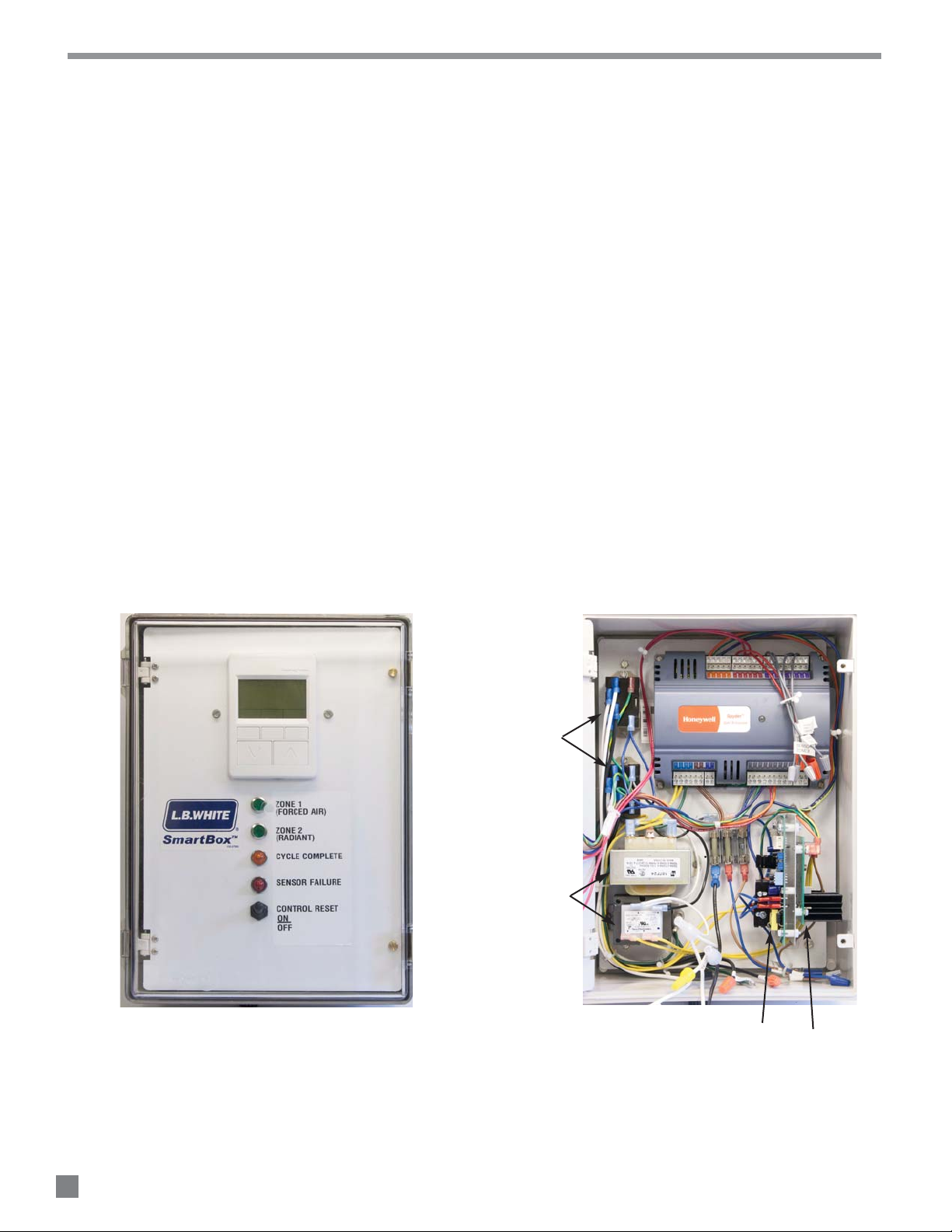
FIG. 1 FIG. 2
TOUCH PAD
AND DISPLAY
RELAYS
TRANSFORMERS
PROGRAMMABLE
CONTROLLER
FUSES
RADIANT FORCED AIR
SIGNAL CONDITIONERS
4
Page 5
Location
Mounting
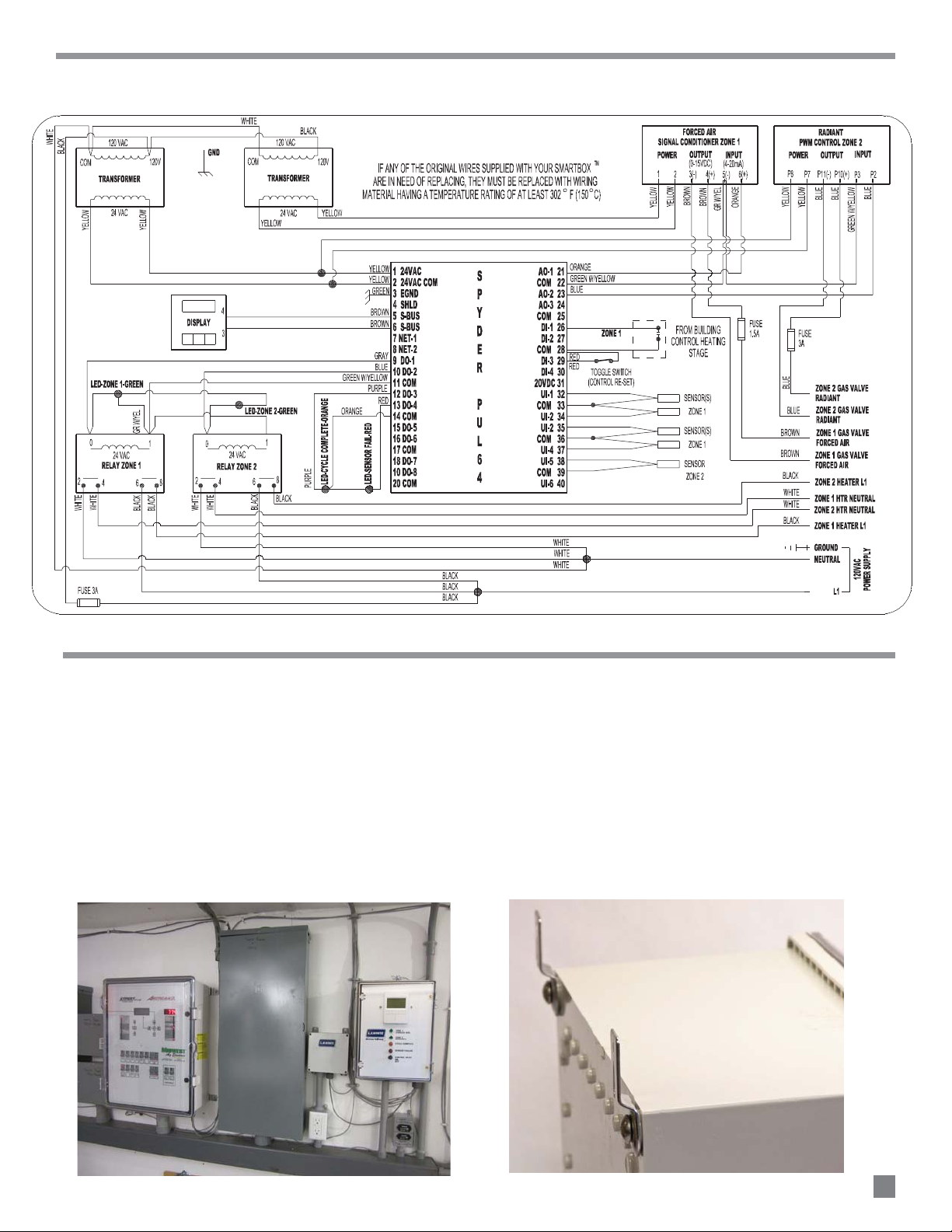
Wiring Diagram
L
-- Locate in a corridor or control room on the wall
adjacent to or close to the existing room controller.
See Fig.3.
-- This area should be dry and not exposed to water
washdown.
-- The temperature in this area must be between 32F
and 104F.
FIG. 3
Locating and Mounting
-- Use mounting tabs and screws provided with the
SmartBox™at all corners of the box back. See Fig.4.
-- Use proper hardware to secure the SmartBox
the wall surface
-- Provide sufficient clearance to allow complete
opening of the SmartBox™cover.
FIG. 4
™
to
5
Page 6
Sensor Location
Each SmartBox™ controls two zones of heat.:
-- Zone 1: Two forced air heaters
-- Zone 2: Radiant heaters
Use only the L.B.White SmartBox
™
sensors provided
wi th th e SmartBox™, or o rde r repl ace men ts as
needed. Do not use sensors from other controller
syst e ms as thes e a re not com p a tibl e w i th the
L.B.White SmartBox
™
.
See below for proper SmartBox™sensor location.
One SmartBox™sensor may be used for each zone of
heat. However two or more sensors are used for
optimum temperature management.
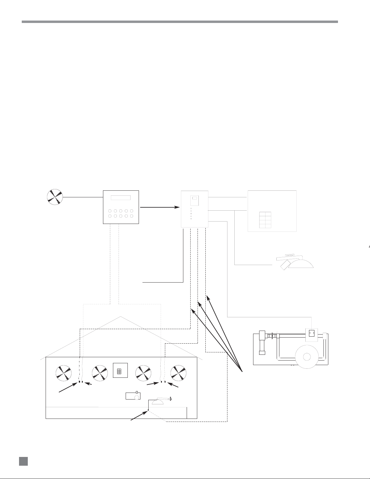
FIG. 5
FAN(S)
ROOM CONTROLLER
SmartBox™ SYSTEM DIAGRAM
FORCED AIR AND RADIANT HEATERS
ZONE1
ZONE2
CYCLE
SENSOR
RESET
™
120 VAC
POWER SUPPLY
SmartBox
ENABLE
GUARDIAN WITH
Smart Sense
™
SmartBox™ SENSOR(S) LOCATED WITHIN 6 IN. OF
EXISTING ROOM SENSOR AND AT SAME HEIGHT
GUARDIAN
GUARDIAN WITH
w/ SMARTSENSE™
™
Smart Sense
ROOM CONTROL SENSORS
ZONE PANEL
RADIANT SENSOR
120 VAC
POWER SUPPLY
SmartBox™ SENSOR(S) LOCATED WITHIN 6 IN. OF
EXISTING ROOM SENSOR AND AT SAME HEIGHT
120 VAC TO SPARK IGNITION
INFRACONICS ONLY (ZONE 2)
CONTROL SIGNAL TO ZONE PANEL VARIABLE RATE
SOLENOID VALVE (USE MINIMUM 18 GAUGE WIRING))
USE 18 GAUGE WIRE FROM THE
SmartBox™TO EACH TEMPERATURE SENSOR
LOCATION. UP TO 4-FORCED AIR AND
1 RADIANT ZONE
6
Page 7
A
All wiring must be done by a qualified electrician in
accordance with local, state, and national electrical
codes.
Do not drill holes
at the top of the control box.
Install the appropriate sized water tight connectors.
Connecting the 120 VAC Power Supply to the SmartBox™.
Connecting 120 VAC Power to the Heaters
Wiring from SmartBox™to the forced air heater’s Smart
Sense™ variable rate gas control valve
WARNING
Electrical Shock Hazard
■
■ Disconnect the electrical supply before installation of
the SmartBox
™
.
■ Failure to follow this warning may result in personal
injury or death.
■ Unlatch the control box cover, and open the control
panel.
■ Select locations on either the side or the bottom where
a wiring access holes may be drilled.
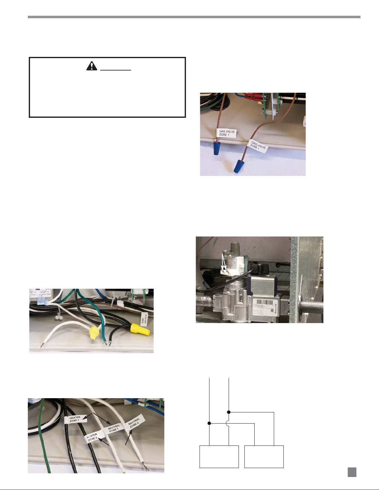
■
Interconnection
a. Connect the Smart Sense™ gas control valve wiring
for Zone 1 at the brown SmartBox
shown in Fig.8.
FIG. 8
™ leads as
■ Use customer supplied minimum 18 gauge conductor
and the appropriate wiring terminals for connecting the
Smart Box™ to the heater’s variable gas control valve,
to the room controller contacts, and the temperature
sensors.
■ Refer to the following instructions for wiring
connections. Refer to the white flags on the
SmartBox™leads for interconnections.
Connect to hot, neutral, and ground leads as shown in
Fig.6.
FIG. 6
b. Route the wiring from these leads through the
gas inlet hole at the heater’s case. See Fig.9.
c. Attach 1/4 in. insulated female terminals to
these wires and connect to either terminal on
the valve. See Fig. 9.
FIG. 9
CONNECT WIRING TO TERMINALS
( NOT POLARITY SENSITIVE)
ROUTE WIRING
THROUGH HOLE
d. See Fig.10 for typical connections. Each SmartBox™
zone can control two heaters.
FIG. 10
Connect leads in SmartBox™to heating Zones 1 and 2.
See Fig.7.
FIG. 7
FORCED AIR
USED FOR SPARK IGNITION
RADIANT HEATERS ONLY. DO
NOT USE FOR MANUAL IGNITION
RADIANT HEATERS
WIRING FROM Smart Box™ To FORCED AIR Smart Sense™
VARIABLE RATE GAS CONTROL VALVE
VALV E
VOLTS TO VALVE
HEATER 1
GAS VALVE
HEATER 2
GAS VALVE
7
Page 8

C
Connecting the building controller’s heating contacts to the
SmartBox™(for contact closure) for Zone 1 forced air heaters.
(Zone 2 is for radiant heaters and operates independent of
the room controller. This does not require contact closure
wiring)
These are
not powered contacts.
Wiring from SmartBox™to the radiant heaters.
Connecting the SmartBox™temperature sensors
(Zone 1 has 4 sensors, Zone 2 has 1 sensor)
See page 6 for sensor location.
Use onl y the L.B. White SmartBox™se nsors, part
num ber 572815, provided with the SmartBox™, or
order replacements as needed. Do not use sensors
from room controllers as these are not compatible with
the L.B.White SmartBox
™
.
FIG. 13
Connect to the red leads as shown in Fig.11.
-- Remove the wiring from the heat contacts (one for
each zone) in the room controller.
-- Connect these same contacts to the SmartBox
Enable wiring Zone 1, and to common Zone 1.
- This allows each SmartBox™ zone
to operate within the temperature
parameters of the room controller.
FIG. 11
™
FIG. 14
COMBO SmartBox
PROPORTIONAL CONTROL VALVE
CONNECTOR BLOCK
2
1
™
-
+
BLUE
BLUE
GROUND
■ The SmartBox™ operates the variable rate proportional
solenoid control used for the radiant heaters, and
operates independent from the room controller.
■ Separate installation and operation instructions
accompany the appropriate control for manual igntion
or spark ignition radiant heaters.
■ See Fig.12 for connection of the SmartBox™ to the
proportional control valve for radiant heaters. Fig13
identifies the proportional valve and Fig.14 illustrates a
typical connection from the SmartBox
™ to the valve.
FIG. 12
Connect 18 gauge (minimum) wiring between the gray
leads as shown in Fig.14 and the SmartBox™sensor.
Solder the connection between the SmartBox™ sensor
and the conductor. Wrap this connection with electrical
tape.
FIG. 14
8
Page 9

Set Up and Programming
TOUCH PAD CONTROL AND DISPLAY
BASIC ROOM CONTROL-TYPICAL SET-UP
As an Example:
Note: The actual average room temperature is what will
become the Set-point for the variable rate
forc
ed air heating.
TEMPERATURE CONTROL PARAMETERS
A. Manual Mode
Note:
B. Temperature Curve:
The touch pad control is an interface device used to
program and operate the control. See Fig. 16 as an
example.
FIG. 16
SOFT KEYS
DOWN UP
■ The following can be programmed from the touch pad:
-- Setting for manual operation.
-- Setting the clock at initial start-up or resetting in the
event of a power failure of more than 24 hours.
-- Enabling or disabling room sensors
-- Correlating the SmartBox
controller sensors
-- Setting the initial temperature set points for each
zone.
-- Setting the initial temperature curve, if one is used.
-- With the system in operation, temperature and day
points can be edited to make changes as needed.
™
sensors to room
■ There are up and down keys to adjust parameters.
■ There are three soft keys used to access and program
entries:
-- Designation for the function of each soft key is
indicated at the bottom of the display screen
within the three boxes. Designations change
depending on operating mode.
■ The SmartBox
controller that has an on/off heat control in order to
provide variable rate heating for the forced air heaters.
The SmartBox
of the room controller.
™
interfaces with an existing room
™
operates radiant heaters independently
■ There is a desired room air temperature -not to be
exceeded- typically called:
-- DRT (Daily Required Temperature) or
-- Set Point
■ The typical swine room control will operate a minimum
ventilation fan plus additional stages of ventilation.
-- If DRT /Set Point is exceeded by room temperature
the ventilation fan will increase in speed to full
output.
-- At some point, if this increased airflow is not
sufficient to cool the room back to the desired
DRT/Set Point, then additional stages of
ventilation are activated.
■ To avoid the situation of heaters causing room air
temperature to increase above the DRT/Set Point
thereby causing increased ventilation to remove the
heated air, the settings for heat “on” and “off” are set
to avoid overshoot and the accompanying waste of fuel.
-- DRT/Set Point is 82 F
-- Heater “on” offset is -3F: heater comes on at 79F.
-- Heater “off” differential is -1F, the heater goes off at
81F. This is below the DRT/set point and intended to
minimize overshoot.
With settings given such as in the previous example:
-- You will typically see 5-6 degrees variation in room
temperature. This variation will be eliminated with
variable heat control.
-- The actual average room temperature due to heating
is about 2F lower than the stated DRT/Set-point
temperature, in this example 80F.
■ There are two ways of utilizing the temperature control:
the operator based on appearance and performance of
the animal.
room controller temperature setting and the SmartBox
temperature setting must be aligned.
curve of temperature vs. days that is used to adjust the
room temperature environment as the animal ages.
: Temperature is adjusted as needed by
To operate in the manual mode, the
there is a defined temperature
™
9
Page 10

I
INITIAL START-UP
INITIAL SET-UP
The following instructions guide you through a step by step
process for setting the various paramete
rs.
HOME SCREENS
MANUAL MODE OR TEMPERATURE CURVE SELECTION
■ Connect to a 120 VAC power supply. Set the reset switch
to the ON position. It will take about 30 seconds for the
touch pad to display the following screen.
FIG. 17
-- Display # 2 shows the actual room temperature for each
zone plus the day in the temperature curve cycle. See
Fig.20.
FIG. 20
FORCED AIR TEMP.
RADIANT TEMP.
If at any time during set-up you want to start over, press the
up/down keys and the center soft key simultaneously to get
back to the Home Screen. Press the right soft key
PARAMETERS, then press right soft key NEXT to scroll to the
area you want to change.
■ Simultaneously press the up/down keys and center soft
key. The following screen is displayed. See Fig.18.
FIG. 18
FORCED AIR TEMP.
RADIANT TEMP.
■ Press right soft key NEXT.
-- Display # 3 shows Set Point for both heating zones
and schedule day. See Fig.21.
FIG. 21
■ Once you have decided which display you want, press the
left soft key DONE to get back to the Home Screen
selection.
■ To continue from the Home Screen, press the right soft key
PARAMETERS. The following screen will be displayed.
■ To access Home Screens, press left soft key SET HOME
SCREEN. See Fig.18.
■ There are three home screen displays:
-- Display #1 shows schedule day. See
Fig.19. Then press right soft key NEXT.
FIG. 19
10
FIG. 22
■ This is the manual temperature override selection,
allowing you to set and hold a specific temperature.
Once the selection has been made, the SmartBox™
will hold this temperature.
Page 11

■ Press the center soft key EDIT. The following screen will be
ENABLE (Manual Mode)
Zone 1 is now in manual override. After ensuring
the room controller and Smart Box
™
set points are
aligned, no further action is needed.
DISABLE (Operating on Temperature Curve)
to operate within the
temperature curve.
--
SET CLOCK (To run the temperature curve the clock must be
set)
TEMPERATURE SENSORS
displayed.
FIG. 23
Press the right soft key NEXT to continue. The screen
shown in Fig.26 will be displayed.
FIG. 26
■ Using the up/down keys, select either “‘ENA” to enable the
manual override or “dSA” to disable the override.
E
-- If enable is selected, press the right soft
key NEXT and then up/down keys to set the
temperature that will be maintained by the
SmartBox
-- Once the temperature has been selected , press the
left soft key DONE.
--
™ . See Fig.24.
FIG. 24
■ Press the right soft key NEXT to continue set-up. The
screen shown in Fig.27 will be displayed.
FIG. 27
■ Press the center soft key EDIT to set the clock.
-- Starting with the Month, use the up/down keys to
select Month, day, year, hour, (Note; AM or PM) and
Minutes.
-- Press left soft key DONE to return to SET CLK.
■ Press the right soft key NEXT to continue set-up.
FIG. 25
-- Selecting disable deactivates the manual override,
allowing the SmartBox
-- Press the right soft key NEXT. The following screen
will be displayed. Complete the same enabling
or disabling process for Zone 2 as you previously did
for Zone 1.
™
■ The following screen is displayed. There are four
temperature sensors for Zone 1(forced air) and one
temperature sensor for Zone 2 (radiant). This screen gives
you the option for either using all sensor for the forced air
zones, or the single radiant sensor. YOU MUST USE AT
LEAST ONE SENSOR.
FIG. 28
11
Page 12

■ Press the center soft key EDIT.
CALIBRATING TEMPERATURE SENSORS
■ Press the up/down keys to enable (ENA) or disabled (dSA)
Zone 1 Temperature Sensor 1. See Fig. 29. Make the
same selections for sensors 2 through 4 for Zone 1.
FIG. 29
■ Once all have been selected for Zone 1, Temperature
Sensor 1 through 4, , press the right soft key NEXT to
access Zone 2, Temperature Sensor 1. Enable the sensor
using the up/down keys. When completed, press the left
soft key DONE.
■ To continue set-up, press right soft key NEXT. The following
screen is displayed.
-- Before making any adjustments, you must allow the
temperature between the room controller sensors
and the SmartBox
-- Once temperatures have stabilized, use the up/down
keys to enter room temperature sensor offset.
■ Press the right soft key NEXT to set temperature offset for
Zone 1, Temperature Sensors 1 through 4. Complete
the same process for Zone 2, Temperature Sensor 1.
Use the up/down keys accordingly.
-- Example: If the room controller reads 70 F and the
SmartBox
by pressing the up key.
■ Press the leftsoft key DONE, then press NEXT. The
following screen is displayed
™ reads 69 F, set the offset temperature 1F
™ sensors to stabilize.
FIG. 32
C
This selection allows correlation between the room
controller’s sensors and the SmartBox™ sensors.
FIG. 30
■ Press the center soft key EDIT. The following screen is
displayed.
FIG. 31
■ Press the center soft key EDIT to view the heat load
percent in Zone 1. See Fig. 33. To view Zone 2, press right
center soft key NEXT
FIG. 33
■ Press the up/down keys and center soft key
simultaneously to exit the set-up mode and to return you
back to the Home Screen. Now determine your
temperature curve.
12
Page 13

D
DEFINING THE TEMPERATURE CURVE
Period DRT Day SmartBox™Set Point
Forced Air Radiant
1 76 F 1 74 F 88 F
2 76 F 7 74 F 85 F
3 76 F 21 74 F 74 F *
4 72 F 35 70 F 60 F
5 70 F
48 68 F 60 F
6 68 F 65 66 F 60 F
7 66 F 70 64 F 60 F
8 64 F 80 62 F 60 F
9 62 F 120 60 F 60 F
10 62 F
180 60 F 60 F
* Typically the radiant heaters will shut off
after 2-3 weeks o
f operation.
SET-UP OF ROOM CONTROL
SET-UP OF SYSTEM TEMPERATURE CURVE
■ The SmartBox™has the capacity for 10 time and
temperature control periods.
-- An example is the following:
Note: For each Period, the Days must be equal to or
greater than the previous period.
Example: Period 3 cannot start at Day 6.
-- Determine the 10 temperature/day period curve.
-- Enter the temperature curve.(See the previous table
example)
-- Set heat “on” offset to -3F (73F)
-- Set the heat “off” differential to 3F (76F), same as the
DRT
- The SmartBox
temperature exceeds DRT or Set-point.
- This allows the SmartBox
operate in the range of 73F to 76F.
™
will turn heating off before
™
to be enabled to
FIG. 35
■ To enter the temperature, press the center soft key EDIT.
The following screen is displayed.
FIG. 36
■ Use the up/down keys to set the Start Temperature for
Zone 1. Press the right soft key NEXT and use the up/down
keys to set Zone 2 Start Temperature.
■ Press the left soft key DONE.
■ Press the up/down keys and the center soft key
simultaneously to enter the set-up mode. The following
screen is displayed.
FIG. 34
■ Press the right soft key PARAMETERS.
■ Continue to press the right soft key NEXT to arrive at the
Temperature Curve Input section. See Fig.35.
■ Press the right soft key NEXT. The following screen is
displayed.
FIG. 37
■ Press the center soft key EDIT. The following screen is
displayed.
FIG. 38
13
Page 14

■ Press the up/down keys to set the Period 2 day as
Set up is complete.
SCREEN DISPLAYS
*
*
* Percentage of operation of variable rate gas control valves
determined with the Temperature Curve.
■ Press the right soft key NEXT. The following screen is
displayed. Enter the desired set point for Period 2 Zone 1
using the up/down keys.
FIG. 39
■ Press the right soft key NEXT and enter the set point for
Period 2 Zone 2 using the up/down keys.
■ Press the left hand soft key DONE.
■ Repeat this this same process for Periods 3 through 10,
setting the number of days and set points.
■ Press the left soft key DONE.
■ Simultaneously press the middle soft key and up/down
S
keys to return to the Home Screen.
-- Z1 OR EN (Zone 1 Override Enabled)
-- Z1 TSP OR ( Zone 1 Temperature Set Point Override)
-- Z1 OR ENA or dSA (Zone 1 enabled or disabled)
-- Z2 OR EN (Zone 2 Overide Enabled)
-- Z2 TSP OR (Zone 2 Temperature Set Point Override)
-- STRT DAY (Start Day)
-- Time
-- SCHD DAY (Schedule Day)
-- ACT Period (Actual Period)
-- RMNG HRS (Remaining Hours)
-- Z1 ACTSP (Zone 1 Actual Set point)
-- Z2 ACTSP (Zone 2 Actual Set Point)
-- Z1 T1, T2,T3 etc (Zone 1 Temperature Sensor 1, etc.)
-- Z2 T1 ( Zone 2 Temperature Sensor 1)
-- Z1 T Avg (Zone 1 Temperature Sensor Average)
-- Z2 T Avg (Zone 2 Temperature Sensor Average)
-- SCHED ER (Schedule Error)
-- HTG STS (Heating Status)
-- Z1 Htg Ld (Zone 1 Heating Load Forced Air)
-- Z2 Htg Ld (Zone 2 Heating Load Radiant)
-- P1 T SP(Period 1 through 10 Temperature Set Point)
-- P-1 Z11 (Set Point for Period 1,Zone 1)
-- P-1 Z-2 (Set Point for Period 2 Zone 2)
-- P2 Day (Period 2 Day through Period 10 Day)
-- Sen Dis (Sensor Disabled)
-- Z1 T1 through T4 (Zone 1 Temperature Sensor 1-4
Disabled)
-- Z 2 T2 (Zone 2 Temperature Sensor 2 Disabled)
-- TMP OF SET( Temperature off set)
-- OF ST T1 (or T2) (Off set Temperature Sensor 1 or 2)
-- Status
-- Set Clk (Set Clock)
-- Month
-- Day
-- Year
-- Hour
-- Minutes
14
Page 15

Maintenance/Cleaning Instructions
Don’t use water or chemicals when cleaning.
WARNING
Electrical Shock Hazard
Fuse A
Fuse B
Fuse C:
WARNING
Electrical Shock Hazard
1. Ensure all water tight connectors on the SmartBox
are securely tightened. Check the interior of the box
for any water/condensation which might have
entered. Replace the connector if necessary.
3. Peridically check all wiring, associated terminals, and
™
electrical components within the controller for
corrosion, frayed or cut insulation, tight connections,
etc. Repair or replace as necessary.
2. Periodically check the SmartBox
fits tightly around the cabinet, and that the cover
gasket is in good condition. (No cuts, nicks etc. ).
™
to ensure its cover
■ Do not disassemble or attempt to repair any
components of the SmartBox™.
■ All component parts must be replaced if defects are
found.
■ Failure to follow this warning will result in shock,
causing injury, or death.
4. Use a soft rag to clean the exterior to prevent
dust/dirt from entering the box when opening for
D
service.
Service Instructions
1. Open the box cover and loosen the panel screws for
access to control components.
2 Disconnect the appropriate electrical leads and
remove the mounting screws for the component being
replaced.
3. For reassembly, reverse the service procedure.
Ensure all electrical connections are tight.
4. The SmartBox
checking components, you will need a volt ohm meter
cable of measuring these voltages.
™
operates on AC and DC volts. When
■ Disconnect the electrical supply before servicing the
SmartBox™.
■ Failure to follow this warning may result in electrical
shock, causing personal injury or death.
There are three 250V fuses in the box. See Fig.40.
incoming power supply.
signal conditioner to the variable rate gas solenoid
on the zone panel.
signal conditioner to the variable rate Smart Sense™
gas control valve.
: 3.0 amp fuse connected to the 120 VAC
: 3.0 amp fuse connected from the radiant
1.5 amp fuse connected from the forced air
5. DO NOT overtighten the small wiring connection
screws used on the programmable controller or the
touch pad display. Overtightening will strip threads.
Snug the screws in.
FUSES
FIG. 40
A B C
15
Page 16

Terminal Function
RELAYS
Upper transfo mer
Lower transformer
Both transformers must supply 24VAC for complete
system operation.
Two relays are mounted in the SmartBox™, each
responsible for supplying power to a maximum of
two heaters.
Upper relay: Supplies power to Zone 2 heaters.
Lower relay: Supplies power to Zone 1 heaters.
Refer to Fig. 41 and following table for connection of
wiring and voltage checks.
The relays have numbers adjacent to the male 1/4
in. male connectors for reference.
T
2 Power supply neutral
4 Neutral for heater
6 120 VAC power to heater
8 120 VAC power to relay
0 Ground for relay
1 24 VAC input for relay coil
TOUCH PAD /DISPLAY
closure (sends 115 VAC from
terminal 8 to terminal 6)
FIG. 41
ZONE 2 RELAY
2
0
4
6
1
8
ZONE 1 RELAY
2
0
4
6
1
8
The touch pad/display allows the user to set up the
SmartBox
™
for system operation, heating days,
temperature, etc.
In the event the pad is being programmed and
erratic displays are observed, or no display, the
display pad must be replaced.
Loosen the small screws securing the brown leads
to the back of the touch pad. See Fig.42.
Remove the sheet metal screws adjacent to the
front of the touch pad.
TRANSFORMERS
There are two transformers with 120 VAC input
voltages.
controller and to the radiant heater signal
conditioner.
signal conditioner for use in operating the variable
rate gas control valves.
- 24 VAC to the programmable
- 24 VAC output to the forced air
FIG. 42
FIG. 43
UPPER TRANSFORMER
LOWER TRANSFORMER
16
Page 17

The controller requires 24 VAC for operation which can
Replacement
or
If transferring the blocks with wiring intact, refer to the
following:
LED BLINK RATE
STATUS
be checked at the terminals shown in Fig 44.
(Without 24 VAC, the controller will not operate the
SmartBox
™
)
FIG. 44
LED
24 VAC INPUT FROM UPPER TRANSFORMER
The controller also includes an LED which provides
operation status. When power is applied, the LED may
appear in one of the conditions given in the following
table:
:
OFF Not applicable No power to controller,
ON ON steady
Not blinking
Very slow blink
(continuous)
Slow blink
(continuous)
1 second ON
1 second OFF
0.5 second ON
0.5 second OFF
low voltage, or controller
damaged
Controller is receiving
power but its internal
processor has
malfunctioned.
Normal operation
Sensor failure
PROGRAMMABLE CONTROLLER
a. Remove all individual wires from the terminal
blocks and reconnect to the replacement
controller
b.Remove the terminal blocks with the wiring intact
from original controller and transfer the blocks to
the replacement controller
a. Use a thin bladed screw driver to evenly raise the
block from its alignment pins on the replacement
controller.
b.Insert the screwdriver blade no more than 1/8 in. to
prevent damage to the alignment pins.
c. Insert the screwdriver blade at one end of the
terminal block and rotate the blade about 1/4
turn.
d. Move to the other end of the terminal block and
do the same. See Fig.45. Repeat the process until
the block is evenly raised about 1/4 in. from the
alignment pins.
e. Once the block has been elevated, grasp the
block at its center and carefully pull the block
straight up.
f. Complete these same steps for removal of the
blocks with wiring from the original controller.
g. Remove respective blocks from replacement
controller using this process.
h.Transfer the blocks with wiring to the replacement:
-- Position the block onto the respective
alignment pins.
-- Press straight down to firmly seat the
block.
-- Repeat the process for all blocks.
FIG. 45
This signal conditioners receives 24 VAC from the
lower transformer in the SmartBox
™
, in addition to
a 4-20 mA input signal from the programmable
controller.
The conditioner sends anywhere from 0-15 VDC to
the heater’s variable rate Smart Sense™gas
control for operation, based upon the 4-20 mA
signal supplied from the programmable controller.
See Fig.46 for reference to terminals on the
conditioner when checking voltage and connection
of wiring.
FORCED AIR SIGNAL CONDITIONER
FIG.46
24 VAC INPUT
FROM LOWER
TRANSFORMER
0-15 VDC OUTPUT
TO GAS CONTROL
4-20 mA INPUT
FROM CONTROLLER
17
Page 18

RADIANT SIGNAL CONDITIONER
This conditioner receives 24 VAC from the upper
transformer in the SmartBox™, in addition to a
4-20 mA input signal from the programmable
controller.
The conditioner then sends control signal of 0-15
VDC to the zone control panel’s variable rate
solenoid valve for operation, based upon the 4-20
mA signal supplied from the programmable
controller.
See Fig.47 for reference to terminals on the
conditioner when checking voltage and connection
of wiring.
NOT USED
4-20 mA INPUT
ROM CONTROLLER
F
GROUND
24 VAC INPUT
FROM UPPER
TRANSFORMER
FIG.47
0-15 VDC OUTPUT TO THE
PROPORTIONAL GAS
SOLENOID VALVE
18
Page 19

DO NO T SERVICE UNL ESS Y OU HAV E BEE N
PROPERLY TRAINED.
Use the green LED on the programmable c ontroller for
assistance in troubleshooting if problems occur. A blink
pattern of 1 second ON, 1 second OFF indicates normal
operation.
• Digital Multimeter
Problems Page
Sequence of Operation
spark iggnition radiant
heaters only
Troubleshooting Instructions
WARNING
Electrical Shock Hazard
READ THIS ENTIRE SECTION BEFORE
BEGINNING TO TROUBLESHOOT PROBLEMS.
■ Troubleshooting this system may require operating the
unit with line voltage present. Use extreme caution
when working on the SmartBox
™
.
■ Failure to follow this warning may result in personal
injury or death.
The troubleshooting flow charts on the following pages
provide systematic procedures for isolating problems. The
charts are intended for use by a QUALIFIED SERVICE
D
PERSON.
Components should be replaced only after each step has
been completed.
The troubleshooting flow charts pertain to forced air, and
radiant heaters, (spark and manual ignition). Unless
otherwise noted, the troubleshooting is the same for all
heaters, regardless if forced air or radiant.
TEST EQUIPMENT REQUIRED
- for measuring AC and DC voltage and
resistance.
INITIAL PREPARATION
■ Check all internal wiring for loose connections and
worn/damaged insulation.
a. 120 VAC is supplied to SmartBox™.
b. Call for heat occurs from building controller.
c. Building controller closes heating contacts
enabling SmartBox
operation.
d. 120 VAC is sent to both transformers and to both
relays.
e. Upper transformer reduces 120 VAC to 24 VAC which
is sent to the programmable controller and radiant
heat signal conditioner.
-- Green LED on blinks 1 second ON, 1 second
Off (Normal operation)
f. Lower transformer reduces the 120 VAC to 24VAC
and sends it to the forced air signal conditioners.
g. Programmable controller sends 24 VAC to both
relays.
-- 24 VAC is used to close the relay coil.
-- Relays send out 120 VAC for power supply to
heaters.
h. Programmable controller sends out 4-20 mA signal to
the signal conditioners.
i. Signal conditioners use the 4-20 mA signal to change
the received 24VAC into 0-15 VDC output (forced air)
and 0-24 VDC (radiant).
-- Forced air signal conditioner sends the 0-15
VDC to the forced air heater’s variable rate
gas control
-- Radiant signal conditioner sends the 0-24
VDC to the proportional solenoid valve.
j. Ignition of gas occurs at a specific rate.
-- Room warms to desired temperature.
k. Building controller and SmartBox
simultaneously to monitor temperature until heat
demand is satisfied.
™
operation for forced air heater
-- Forced air or
-- Heaters start the ignition cycle
™
work
Green LED on controller is steady ON
. . . . . . . . . . . . . .20
Green LED on controller is OFF. No display at touch
pad, indicator lights are out, heaters do not operate
. .20
Green LED on controller is blinking 0.5 seconds ON,
0.5 seconds OFF. Red sensor failure light is on . . . . .21
Forced air or spark ignition heaters do not start, but
zone light is ON. . . . . . . . . . . . . . . . . . . . . . . . . . . . . . .21
Zone 1 forced air or Zone 2 radiant heaters do not
start. Zone 1 or 2 LED os OFF, but touch pad is
functional . . . . . . . . . . . . . . . . . . . . . . . . . . . . . . . . . . .21
Heaters start and operate properly, but zone
LED is off. . . . . . . . . . . . . . . . . . . . . . . . . . . . . . . . . . . .22
Heaters in zone start, but heat output does not
change is response to SmartBox
™
setting . . . . . . . . . .22
SmartBox™ Zone 1 (forced air) does not operate
concurrently with room controller . . . . . . . . . . . . . . . .22
19
Page 20

Green LED on
programmable
controller is
steady ON
Green LED on
programmable
controller is
OFF.
No display at
touch pad, all
indicator lights
are off.
Heaters d
o not
operate.
Problem 2
Yes
Problem 1
Is
upper transformer
delivering 24 VAC to
Yes
Is upper
transformer
Yes
controller?
programmable
power fuse?
receiving 120
VAC from main
No
Verify 24 VAC between the two
yellow leads, (Terminals 10 and 6)
of the transformer. If absent,
No
needed.
Defective electrical wire or
connection. Repair or replace as
replace the transformer.
OFF and then
™
Cycle the power to the
Smart Box
controller.
steady ON, replace the
ON. If the LED remains
™
fuse in Smart Box
Is main power supply
delivering 120 VAC to
Yes
?
™
Is 120 VAC
delivered to
Smart Box
transformers?
No
No
Check breakers in building.
continuity.
by checking voltage to
and from fuse or check
Replace the fuse. Verify
Check power outlet for
Check power cord for tight
defects, corrosion, etc.
connections and continuity.
No
controller?
18 VDC from
Is touch pad receiving
controller.
controller terminals 5 and 6 (brown). If
Check for 18VDC at the programmable
present at the programmable controller,
VDC is absent, trace the wires back to the
Check across brown wires at touch pad. If 18
repair or replace wiring between the touch
pad and the programmable controller. If
absent, replace the programmable controller.
20
G
Page 21

Green LED on
programmable
controller is
blinking 0.5
seconds ON,
0.5 seconds
OFF
Red sensor
failure light is
o
n.
Problem 3
Forced air or spark
ignition radiant
heaters do not start,
zone light is ON.
Problem 4
Zone 1 forced air or
Zone 2 radiant
heaters do not start,
Zone 1 or 2 LED is
OFF. Touch pad
display is fun
ctional
Problem 5
OFF and then
™
Cycle the power to the
ON. If the LED remains in
SmartBox
this blink pattern, replace
the programmable controller.
Yes
No
Have sensors
continuity across
been checked for
the sensor leads?
Yes
sensor.
oberved, replace the
Check continuity across
sensor leads. Reading
overload or infinity is
20 k ohm. If a reading of
should be in the range of
for troubleshooting.
not functioning, there is a
at the heater but heater is
If 120 VAC is being received
fault in the heater. Refer to
the heater’s Owner’s Manual
Yes
Is 120 VAC
delivered at
heaters?
No
Yes
heaters?
out 120 VAC to
Is relay sending
Yes
Repair or replace.
outlets, and electrical
connections to the heater.
Check power supply wiring ,
No
relay is not sending 120 VAC,
from programmable controller.
If 24 VAC is present at relay, but
Ensure relay is receiving 24 VAC
replace the relay.
controller is defective.
If good, the programmable
check wiring and connections.
from programmable controller,
If 24 VAC is not received at relay
tight at
connectors
Are all sensor
secure and water
?
™
in the
SmartBox
appropriate leads
sensor leads.
™
No
corrosion, etc.
Verify proper connection of zone
Ensure good, tight connections, no
sensors to SmartBox
Press right soft key VIEW to determine
No
supply?
VAC power
power from 120
Is relay receiving
needed.
Check electrical connections,
wiring, etc. Repair or replace as
tripped circuit breaker, defective
FORCED AIR HEATERS ONLY
Verify room controller is calling for heat
which sensor (T1 or T2) is inoperative.
the touch pad.
FORCED AIR AND RADIANT: Verify
temperature set-point for the zone, using
21
Page 22

Heaters start but
heat ouptut does
not change in
response to
SmartBox
™
setting.
Problem 7
Radiant heaters:
Forced Air Heaters:
Radiant Heaters
Forced Air
Radiant:
SmartBox
™
Zone 1
(forced air) does not
operate concurrently
with room controller.
Problem 8
Heaters start
and operate
properly, but
zone light is
OFF
Problem 6
Check for
gas supply
blockages in
Yes
proportional valve
receiving 1-15 VDC
the radiant heater’s
Is the Smart Sense™
forced air gas valve or
Yes
™
continuity?
the SmartBox
Have the variable
been checked for
rate output fuses of
from fuse?
No
for the specific heater to a
™
higher temperature (at least 10F) over room
temperature.
A. Set the SmartBox
No
defective, replace.
Check the fuses. If
Measure across terminals at
: Loosen the proportional gas
valve to obtain reading
B. Verify increase in VDC to gas valve.
valve’s housing screw and pull back the connector
block sufficiently to allow voltage meter probes to
be inserted at the valve terminals.
: Terminals 3 and 4 (brown wires)
Terminals 10 and 11 (blue wires).
C. If no increase in VDC (should be 13-15 VDC) at
gas control, then check the output at the
respective signal conditioner terminals:
If 13-15 VDC is measured at output but not at
valve, check all wiring and terminals between
the signal conditioner and variable rate valve.
D. If no reading is given at the output of the forced
air or radiant signal conditioner, then the signal
conditioner for that zone of heaters is defective
and must be replaced.
LED.
absent, repair wiring
between controller and
If present replace LED. If
Verify 24 VDC to zone LED.
controller and LED.
between programmable
Zone LED is defective or
poor electrical connecton
™
sensors
Are SmartBox
Yes
Are sensors
Yes
sensors?
same height as
the room control
positioned to the
properly?
positioned
No
No
Reposition the sensors. Refer
cold spots, etc.
away from drafts, air inlets,
Ensure all sensors are located
to sensor location
instructions in this manual.
Ensure the
radiant sensor bracket is
installed and that the sensor
to 3/16 in. from the end of
is located properly within its
housing. It should be 1/8 in.
and inside the sensor housing.
and the
™
Check temperature curve for
both the SmartBox
room controller. Verify the
temperatures match.
22
Page 23

Warranty Policy
L.B. White Co., Inc. warrants that the component parts are
free from defects in material and workmanship, when
properly installed, operated, and maintained in accordance
with the Installation and Maintenance Instructions, safety
guides and labels contained with each unit. If, within 12
months from the date of purchase by the end user, any
component is found to be defective, L.B. White Co., Inc. will
at its option, repair or replace the defective part or heater,
with a new part or heater, F.O.B., Onalaska, Wisconsin.
L.B. White Co., Inc. warrants that replacement parts
purchased from the company and used on the appropriate
L. B. White equipment are free from defects both in material
and workmanship for 12 months from the date of
purchase by the end user. Warranty is automatic if a
component is found defective within 12 months of the date
code marked on the part. If the defect occurs more than 12
months later than the date code but within 12 months from
the date of purchase by the end user, a copy of a bill of sale
will be required to establish warranty qualification.
The warranty set forth above is the exclusive warranty
provided by L.B. White, and all other warranties, including
any implied warranties or merchantability or fitness for a
particular purpose, are expressly disclaimed. In the event
any implied warranty is not hereby effectively disclaimed
due to operation of law, such implied warranty is limited in
Smart Box
A warranty card on file at L.B. White will automatically
qualify a unit and its component parts for warranty
consideration. If a warranty card is not on file, a copy of the
bill of sale will be required to establish warranty
qualification. If neither is available, the warranty period will
be 12 months from date of shipment from L B. White.
™
Parts
duration to the duration of the applicable warranty stated
above. The remedies set forth above are the sole and
exclusive remedies available hereunder. L.B. White will not
be liable for any incidental or consequential damages
directly or indirectly related to the sale, handling or use of
the equipment, and in any event L.B. White's liability in
connection with the equipment, including for claims based
on negligence or strict liability, is limited to the purchase
price.
Some states do not allow limitations on how long an implied
warranty lasts, so the above limitation may not apply to you.
Some states do not allow the exclusion or limitation of
incidental or consequential damages, so the above
limitation or exclusion may not apply to you. This warranty
gives you specific legal rights, and you may also have other
rights which vary from state to state.
Contact your local L.B. White dealer for replacement parts
and service or call the L.B. White Co., Inc. at 1-800-345-7200
for assistance. Be sure that you have your model number
and serial number when calling.
Replacement Parts and Service
23
 Loading...