


LRP-1
LBC Bakery Equipment Co. 1410 80
th
St. South West Suite C Everett, WA 98203
Part # Phone: 888-722-5686 Fax: 425-642-8305
Rev. B 2006 WWW.LBCBAKERY.COM © Copyright 2002
LBC Bakery Equipment Co. 1410 80
th
St. South West Suite C Everett, WA 98203
Part # Phone: 888-722-5686 Fax: 425-642-8305
Rev. B 2006 WWW.LBCBAKERY.COM © Copyright 2002
THE INFORMATION IN THIS MANUAL IS CRUCIAL AND MUST BE RETAINED FOR
FUTURE REFERENCE. READ, UNDERSTAND, AND FOLLOW THE INSTRUCTIONS AND
WARNINGS CONTAINED IN THIS MANUAL.
DANGER
POTENTIALLY HAZARDOUS SITUATION WHICH, IF NOT
AVOIDED, COULD RESULT IN DEATH.
WARNING
POTENTIALLY HAZARDOUS SITUATION WHICH, IF NOT
AVOIDED, COULD RESULT IN DEATH OR SERIOUS INJURY.
CAUTION
POTENTIALLY HAZARDOUS SITUATION WHICH, IF NOT
AVOIDED, MAY RESULT IN MINOR OR MODERATE INJURY.
NOTICE
Helpful operation and installation instructions and tips are
present.
FOR YOUR SAFETY
DO NOT STORE OR USE GASOLINE OR OTHER FLAMMABLE VAPORS
AND LIQUIDS IN THE VICINITY OF THIS OR ANY OTHER APPLIANCE.
WARNING: IMPROPER INSTALLATION, ADJUSTMENT, ALTERATION,
SERVICE OR MAINTENANCE CAN CAUSE PROPERTY DAMAGE, INJURY
OR DEATH. READ THE INSTALLATION, OPERATING AND MAINTENANCE
INSTRUCTIONS THOROUGHLY BEFORE INSTALLING OR SERVICING THIS
EQUIPMENT.
Model #: Purchased From:
Serial #:
Location:
Date Purchased:
Date Installed:
Purchase Order #:
For Service, Call:

TABLE OF CONTENTS
CHAPTER PAGE
TABLE OF CONTENTS ...................................................................................... 3
READ FIRST ........................................................................................................ 4
SAFETY PROCEDURES ..................................................................................... 6
EQUIPMENT DESCRIPTION ............................................................................. 7
GENERAL DESCRIPTION.................................................................................. 8
GENERAL OPERATION..................................................................................... 9
GENERAL MAINTENANCE .............................................................................. 10
ASSEMBLY.......................................................................................................... 11
WIRING DIAGRAMS.......................................................................................... 33
PARTS LIST ......................................................................................................... 35
LRPR RETARDER MANUAL............................................................................. 40
LRPR RETARDER MANUAL TABLE OF CONTENTS................................... 42
LRPR RETARDER INSTALLATION ................................................................. 50
LRPR RETARDER PARTS LIST ........................................................................ 62
LRPR RETARDER WIRING DIAGRAM ........................................................... 64
WARRANTY........................................................................................................ 65
ETL File E8138 Rev. B2006
4
IMPORTANT READ FIRST IMPORTANT
WARNING
MOVING PARTS HAZARD. FOLLOW LOCKOUT PROCEDURES BEFORE
REMOVING AIR DUCT OR EVAPORATOR FAN GUARDS
WARNING
ELECTRICAL HAZARD BEHIND UPPER FRONT TRIM. FOLLOW LOCKOUT
PROCEDURES BEFORE SERVICING.
WARNING
THE LBC BAKERY LRP SERIES PROOFER PRODUCES HUMIDITY WHICH
WILL NATURALLY CONDENSE AND ACCUMULATE WATER ON THE
INTERIOR FLOOR CAUSING IT TO BECOME SLIPPERY. ADJACENT
EXTERIOR FLOOR MAY ALSO BECOME SLIPPERY. USE EXTREME
CAUTION WHEN WALKING IN OR AROUND THIS APPLIANCE.
NOTICE
This picture shows an LRP1, LRP2, and LRP3. The LRP1 and some LRP2
models have only one climitizer. Larger models have two climitizers.
DANGER
DO NOT STORE OR USE GASOLINE OR OTHER FLAMMABLE VAPORS OR
LIQUIDS IN THE VICINITY OF THIS OR ANY OTHER APPLIANCE.
NOTICE
For best results, always allow your proofer to reach set temperature and
humidity before putting product in.
NOTICE
For best results, proof at lower temperatures rather than higher.
NOTICE
To dry proof: Set humidity to the lowest setting (either 45% or less). At
this setting the humidity generator is turned off and will not produce
humidity.
NOTICE
When the actual humidity is less than 46% display will show 45. When the
actual humidity is higher than 45%, display will show the actual humidity.
NOTICE
Service on this or any other LBC BAKERY equipment must be performed
by qualified personnel only. Consult your authorized service agency
directory or call the factory at 1-888-722-5686 or go to
WWW.LBCBAKERY.COM for the service agent nearest you.
NOTICE
The LRP1 has hinges mounted on the right jamb only.
CAUTION
THIS APPLIANCE, WHEN INSTALLED, MUST BE ELECTRICALLY
GROUNDED IN ACCORDANCE WITH LOCAL CODES, OR IN THE
ABSENCE OF LOCAL CODES, WITH THE NATIONAL ELECTRICAL CODE,
ANSI/NFPA 70-1996.

ETL File E8138 Rev. B2006
5
IMPORTANT READ FIRST IMPORTANT
CAUTION
FOR INSTALLATION IN CANADA THE INSTALLATION MUST BE IN
ACCORDANCE WITH CAN/CGA-B149.1&2 OF THE INSTALLATION CODE,
AND LOCAL CODES WHERE APPLICABLE. ALL ELECTRIC WIRING MUST
BE IN ACCORDANCE WITH THE CURRENT CANADIAN ELECTRICAL
CODE, C22.1 PART 1. GROUNDING THIS APPLIANCE MUST CONFORM
TO CANADIAN ELECTRICAL CODE, CSA C22.2.
WARNING
INSTALLATION OF THE UNIT MUST BE DONE BY PERSONNEL QUALIFIED
TO WORK WITH ELECTRICITY AND PLUMBING. IMPROPER
INSTALLATION CAN CAUSE INJURY TO PERSONNEL AND /OR DAMAGE
TO EQUIMENT. UNIT MUST BE INSTALLED IN ACCORDANCE WITH ALL
APPLICAL CODES

ETL File E8138 Rev. B2006
6
SAFETY PROCEDURES
WARNING
MOVING PARTS HAZARD. FOLLOW LOCKOUT PROCEDURES BEFORE
REMOVING AIR DUCT OR EVAPORATOR FAN GUARDS
WARNING
ELECTRICAL HAZARD BEHIND UPPER FRONT TRIM. FOLLOW LOCKOUT
PROCEDURES BEFORE SERVICING.
WARNING
THE LBC BAKERY LRP SERIES PROOFER PRODUCES HUMIDITY WHICH
WILL NATURALLY CONDENSE AND ACCUMULATE WATER ON THE
INTERIOR FLOOR CAUSING IT TO BECOME SLIPPERY. ADJACENT
EXTERIOR FLOOR MAY ALSO BECOME SLIPPERY. USE EXTREME
CAUTION WHEN WALKING IN OR AROUND THIS APPLIANCE.
Lockout Procedure
1. Announce lockout to other personnel.
2. Turn both heat and control power off at main panel.
3. Clear unit of all personnel.
4. Test lockout by turning power switch on and observing if control panel displays or fan(s) come on.
Check heater circuit with voltmeter.
5. Perform necessary repairs or tests.
6. Clear unit of personnel before restarting.
7. Turn power on at main panel.
8. Announce unit is “on” to other personnel.
Safety Precautions
LBC Bakery Equipment hereby disclaims any and all responsibility for injury, damage, loss or other
claim that may occur to person or property from improper alteration, modification, addition, operation,
maintenance or service, whether it be mechanical, electrical, fuel, operator, motor or otherwise, which
may occur from such improper alteration, modification, addition, operation, maintenance or service to this
piece of equipment.
Safety Considerations
Your LBC Bakery LRP Proofer is manufactured to rigid standards. This equipment is E.T.L. listed and
meets safety and sanitation standards.
The presence of safety equipment control and interlocks on an appliance and attendant components of
installation cannot, in and of themselves, assure absolute safety of operation. Diligent, capable, well
trained operators and maintenance personnel, as well as proper programs of operation and maintenance,
are essential to the safe and reliable operation of this appliance.
A. The responsibility of the manufacturer
is to supply suitable, comprehensive instructions and
recommendations for the operation and maintenance of the appliance.
B. Trained, qualified and factory-authorized personnel must perform all operation, maintenance and
repair of these appliances. It is the responsibility of the owner / operator
to ensure that this
happens.
C. A regular periodic program of cleaning, inspection and maintenance must be established and
comprehensive maintenance records maintained. It is the sole responsibility of the user
to establish,
schedule and enforce the frequency and scope of these programs in keeping with recommended
practice and with due consideration given to actual operating conditions.
D. The appliance must be operated within limits which will not exceed the working limits of any
component within the appliance as a whole.

ETL File E8138 Rev. B2006
7
EQUIPMENT DESCRIPTION
Exterior
LRP1
• The Proofer exterior dimensions are 38.4” (97.5 cm) wide x 91.5” (232.5 cm) high x a depth dependent
upon model number [39.3”(100 cm) to 129.3” (328.5cm)]. The Top, Front, Back, and Sides are
constructed of stainless steel.
LRP2
• The Proofer exterior dimensions are 78.8” (200 cm) wide x 91.5” (232.5 cm) high x a depth dependent
upon model number [39.3”(100 cm) to 129.3” (328.5cm)]. The Top, Front, Back, and Sides are
constructed of stainless steel.
LRP3
• The Proofer exterior dimensions are 102.5” (260 cm) wide x 91.5” (232.5 cm) high x a depth dependent
upon model number [39.3”(100 cm) to 129.3” (328.5cm)]. The Top, Front, Back, and Sides are
constructed of stainless steel.
All Units
• Modular design allows for a wide variety of sizes.
• The proofer door is constructed of stainless steel and comes with both single and double doors.
Interior
LRP1
• The Proofer interior dimensions are 33.1” (84 cm) wide x 74.1” (188.1 cm) high x a depth dependent upon
model number [22.1”(56 cm) to 112.1” (284.7 cm)]. The Top, Front, Back, and Sides are constructed of
stainless steel.
LRP2
• The Proofer interior dimensions are 68.1” (173 cm) wide x 74.1” (188.25 cm) high x a depth dependent
upon model number [27.1”(68.8 cm) to 117.1” (297.4 cm)]. The Top, Front, Back, and Sides are
constructed of stainless steel.
LRP3
• The Proofer interior dimensions are 91.8” (233cm) wide x 74.1” (188.25 cm) high x a depth dependent
upon model number [27.1”(68.8 cm) to 117.1” (297.4 cm)]. The Top, Front, Back, and Sides are
constructed of stainless steel.
All Units
• Floor level loading.
Cabinet
Rigid, formed stainless steel panels filled with polyurethane foam insulation re-joined with cam-locks and
sealed with gaskets to form a strong, energy-efficient, tight and sanitary enclosure.
Doors
The welded stainless steel door is polyurethane foam-filled. Door bumpers on the inside protect the finish.
Controls
• The microprocessor-based digital controls are mounted for ease in the door. In some models power and
light switches are located above the door.
• Digital read-out with solid-state temperature sensing and controls.
Air-Duct(s)
Each proofer comes with one or two air ducts. These air ducts perform the tasks of heating, humidifying,
and circulating the air within the unit. Each duct contains a heater plate, spray nozzle, drain pan, and fan.

ETL File E8138 Rev. B2006
8
GENERAL DESCRIPTION
Theory of Operation
The LBC Bakery Proofer is a controlled atmosphere chamber. Temperature and humidity can be set
independently to meet your particular proofing needs. In Proof mode air temperature is increased as the air
duct heater is energized. Humidity is increased as water is sprayed in the air duct. Air is circulated
continuously to provide positive movement from bottom to top, creating a uniform distribution of warm,
humid air.
Proofer Theory
NOTICE
This picture shows an LRP2. The LRP1 has only one door and the air duct
heater is mounted on the back wall.
ETL File E8138 Rev. B2006
9
GENERAL OPERATION
DANGER
DO NOT STORE OR USE GASOLINE OR OTHER FLAMMABLE VAPORS OR
LIQUIDS IN THE VICINITY OF THIS OR ANY OTHER APPLIANCE.
NOTICE
For best results, always allow your proofer to reach set temperature and
humidity before putting product in.
NOTICE
For best results, proof at lower temperatures rather than higher.
NOTICE
To dry proof: Set humidity to the lowest setting (either 45% or less). At this
setting the humidity generator is turned off and will not produce humidity.
NOTICE
When the actual humidity is less than 46% display will show 45. When the
actual humidity is higher than 45%, display will show the actual humidity.
See Programming Manual for Operation Instructions!

ETL File E8138 Rev. B2006
10
GENERAL MAINTENANCE
WARNING
THE LBC BAKERY LRP SERIES PROOFER PRODUCES HUMIDITY WHICH
WILL NATURALLY CONDENSE AND ACCUMULATE WATER ON THE
INTERIOR FLOOR CAUSING IT TO BECOME SLIPPERY. ADJACENT
EXTERIOR FLOOR MAY ALSO BECOME SLIPPERY. USE EXTREME
CAUTION WHEN WALKING IN OR AROUND THIS APPLIANCE.
NOTICE
Service on this or any other LBC BAKERY equipment must be performed by
qualified personnel only. Consult your authorized service agency directory
or call the factory at 1-888-722-5686 or go to WWW.LBCBAKERY.COM for
the service agency nearest you.
Every Day
Clean interior and exterior of proofer. See Equipment Cleaning instructions @ WWW.LBCBAKERY.COM under
manuals tab.
Every Six Months
Have factory authorized service personnel check proofer for proper temperature readings. Also inspect air duct drain,
heater plate, spray nozzle for proper operation and mineral deposits; de-scale as needed.
As Needed
Clean interior and exterior walls and replace light bulb or any other components as needed.
Specifications
Temperature, humidity, and timer setting ranges:
Thaw:
70-120°F (18-66°C)
50-95% Relative Humidity
Proof:
70-120°F (18-46°C)
50-95% Relative Humidity
Timers:
0-99 Hours and 0-99 Minutes
Power:
Varies depending on model and size (See data plate located on the underside of the valence
for the specific ratings or contact the factory for the information needed if the data plate is
not legible).
Water
Consumption:
.73 gallons per hour average per air duct (2 ducts maximum) @ 30 PSI.
1.70 gallons per hour average per air duct (2 ducts maximum) @ 80 PSI.
Unit will use about 4 gallons per hour when powered on until humidity levels reach set point.
Technical Data Part # Ohms
Elements 11162-09 26Ω
Solenoid Valve 70403-01 8 Ω
Contactor 30700-06 6 Ω
Relay 30701-05 35 Ω
Transformer 31400-26 240V primary 75 Ω, 208V primary 64 Ω, 24V secondary 1 Ω
Blue to Black Red to Black Yellow to Yellow (no red stripe)
ETL File E8138 Rev. B2006
11
ASSEMBLY
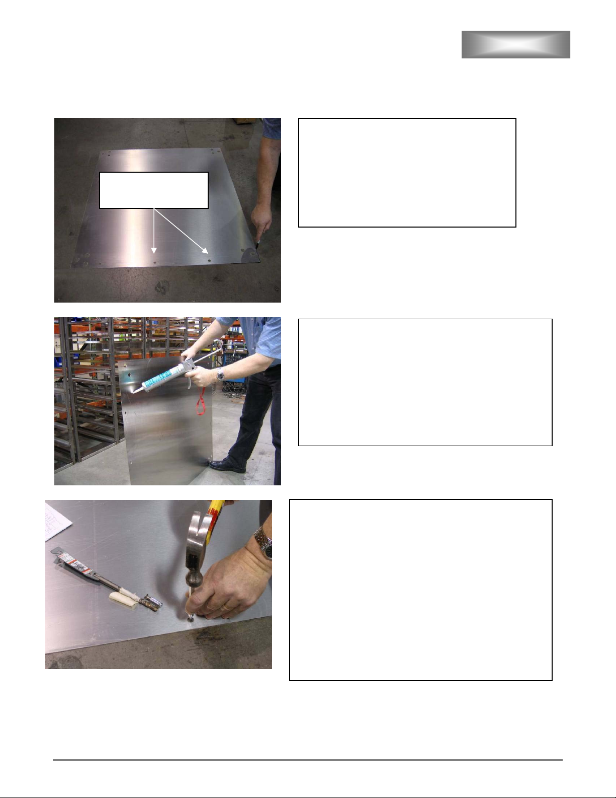
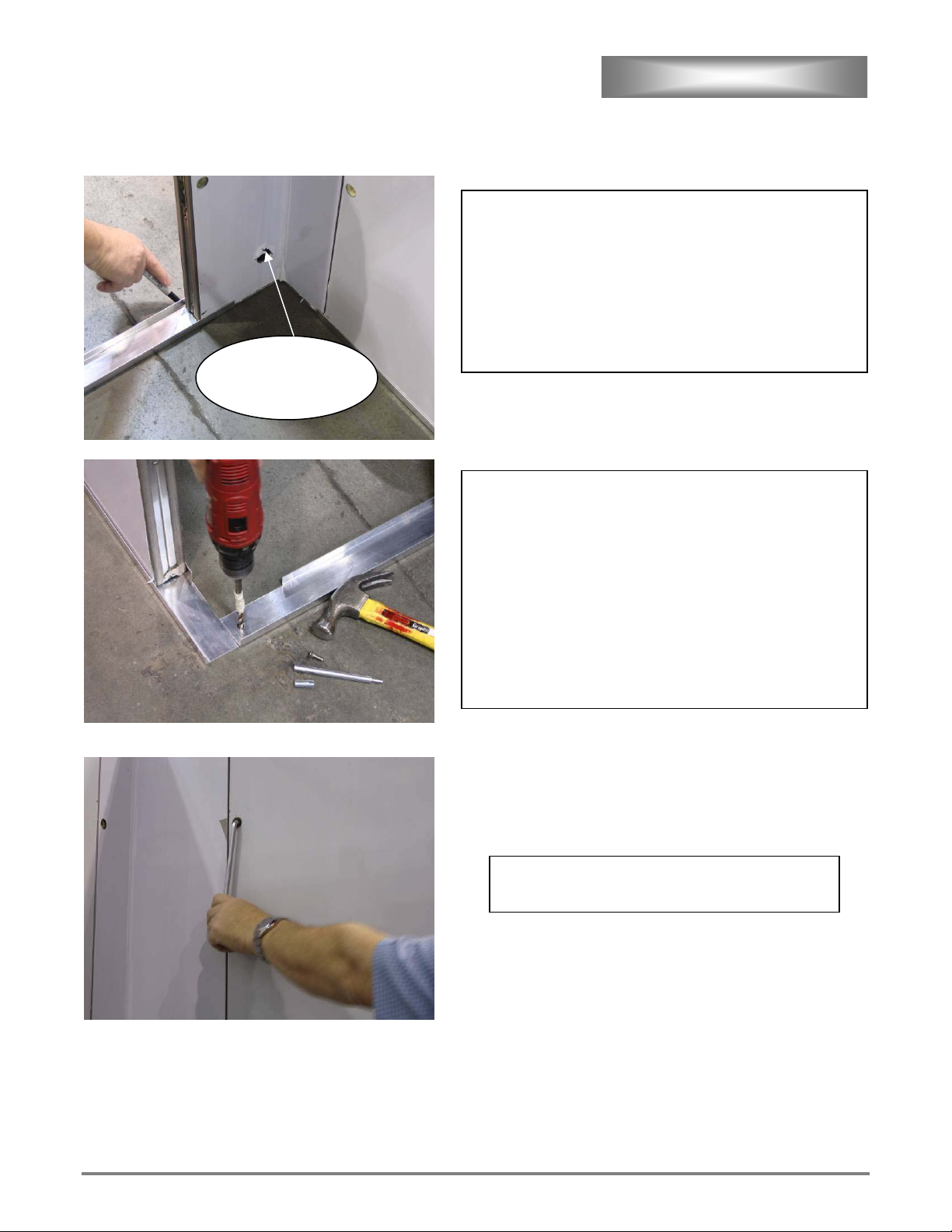
NOTE: ON UNITS WITH FLOOR ONLY!
One good blow is better then many small taps when installing anchors.
Drill holes with rotary drill and install anchors in front row
(and middle row if applicable). Drill 10MM diameter hole
1 ½” deep and remove all dust from hole. Do not drill too
deep. Install anchor with provided insert tool.
Note: If concrete subfloor has additional
layer of softer leveling slag and anchors
do not hold, a longer anchor bolt may be
necessary.
Do not install anchors at edges or corners at this time.
Place floor adhesive onto floor and spread with provided
trowel. Seal bottom with a good continuous bead along
edge before setting into final resting position. Apply
weight to floor while adhesive sets.
Note: Row of 3/8” holes is front of
floor. Countersunk sides of holes go up.
Place floor onto prepared surface and mark
position. Take into consideration drain location.
Note: Tile that may come loose
over time should be removed.
Countersunk sides of
holes go up.
ETL File E8138 Rev. B2006
12
ASSEMBLY CONT’D
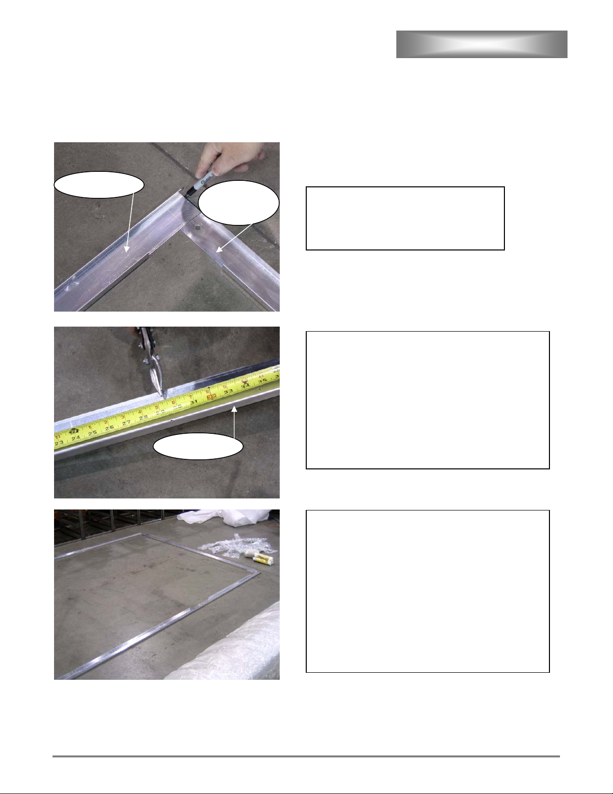
Note: Units without Stainless Floor start here
.
Place wall base channels as pictured. Outside
dimensions should match Specification
Sheet. Mark outside edge with non
permanent marker.
Optional: Seal base channels with small amount of
silicone to stop leaks from developing at bottom of unit.
Press base channel to floor.
Note: Recheck dimensions to insure
wall panels fit into track. Once
silicone dries, base channels are hard
to move. See Spec. Sheet.
See wall panel location Chart 1 for panel placement.
Each proofer is supplied with enough track to install a
120” deep proofer.
Holes in side channel indicate cutting points for base
channels. Cut side channels short enough to leave front
corners exposed.
You may need both channel pieces depending on the
size of the proofer.
No base channel on door side of proofer.
Rear Base
Channel
Side Chanel
Side Chanel
ETL File E8138 Rev. B2006
13
ASSEMBLY CONT’D
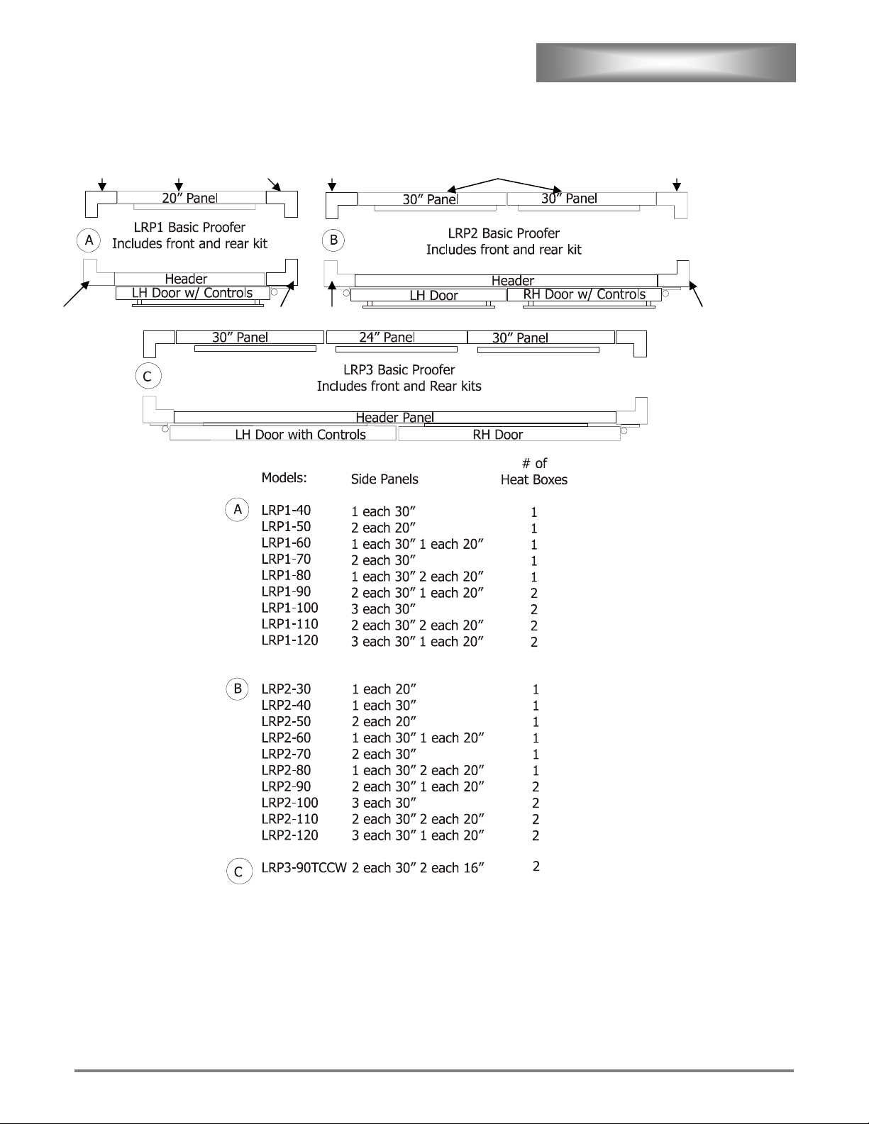
Chart 1,
Panel locations
Ceiling Panels should match side wall panels.
Example: On a LRP2-30 you should have 1 20” ceiling and 2 20” wall panels.
71100-12 15.25” Bumper for Climitizer and 20” Panels
71100-13 23.5” Bumper for 30” Panels
71100-14 31.5” Bumper for 3 hole doors
71100-15 40” Bumper for 4 hole doors
155-707 155-709 155-706 155-707
155-706-4 155-710
155-709155-705-10 155-710 155-705
ETL File E8138 Rev. B2006
14
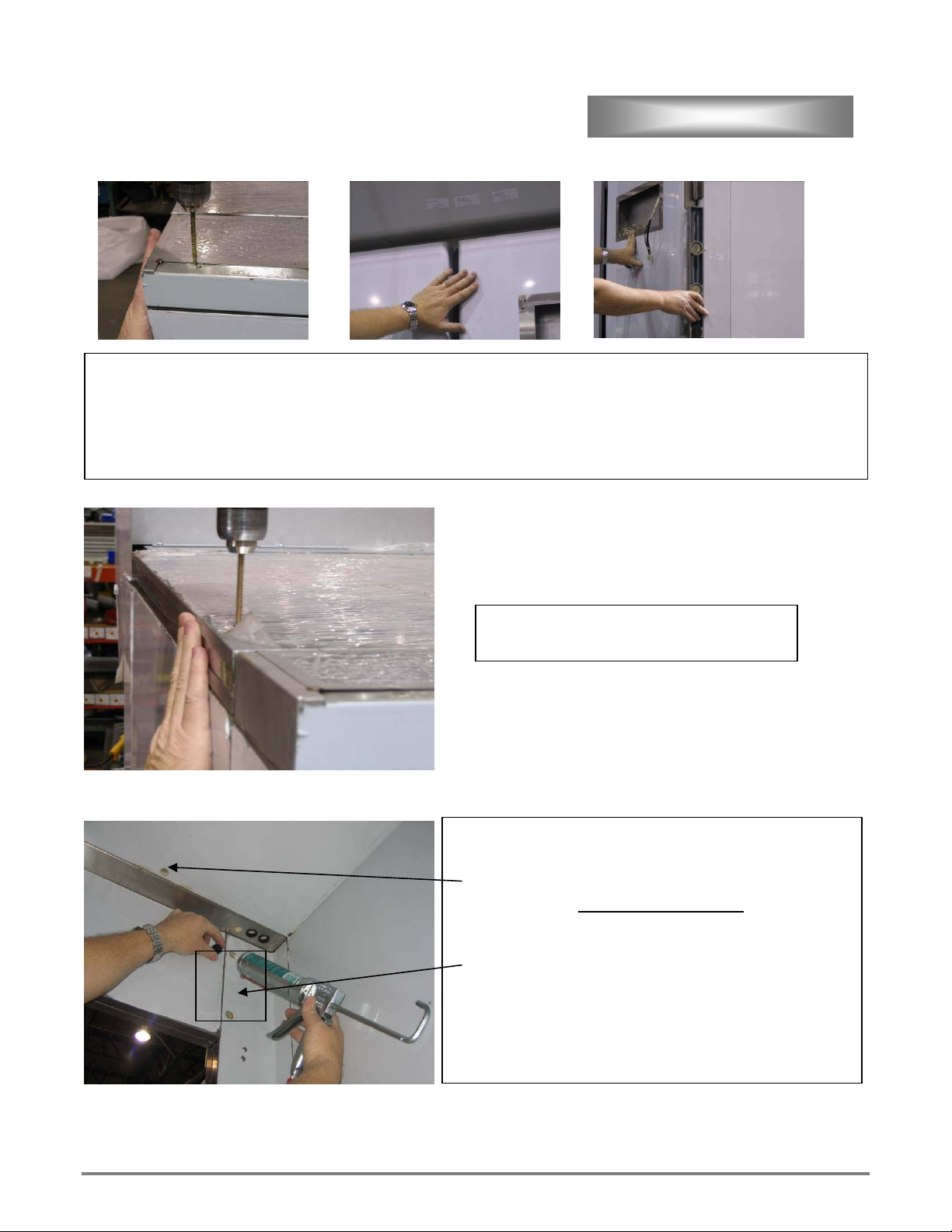
ASSEMBLY CONT’D
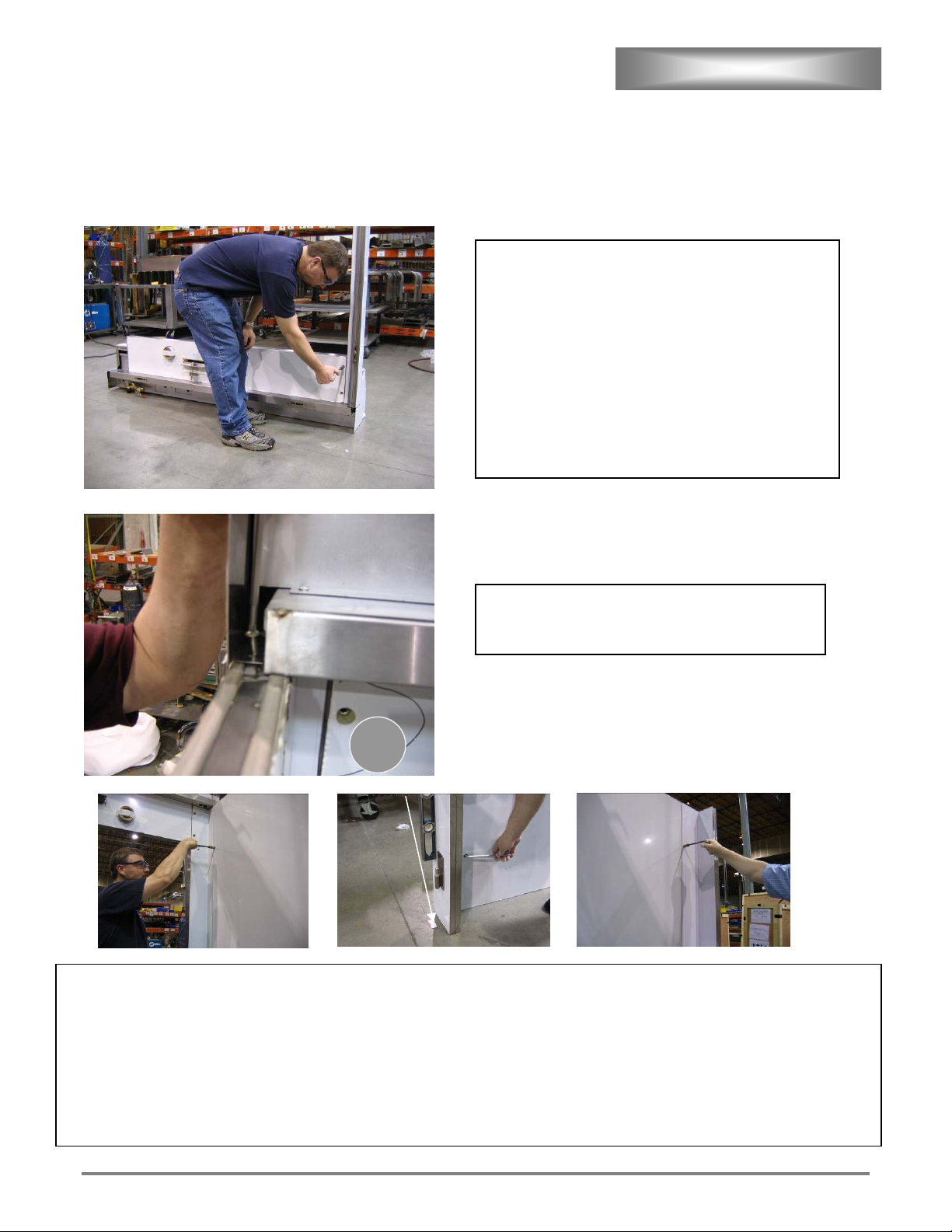
Note: When locking a cam it may be necessary
to first rotate cam all the way back until a
positive click is heard. This will ready the cam
for locking. DO NOT OVER TIGHTEN! Over
tightening will damage the cam.
Once the cam is reset it will not click again until you attempt
to lock the cam into its receiver, or onto a screwdriver shaft.
If cam will not reset or lock, lubricate cam with WD-40® or
equivalent and work cam open and closed until it resets and
locks.
If front corners have two screws installed,
remove two screws from each front corner
panel top. These screws will later be reused
to secure the valance.
Place header assembly on floor upside down.
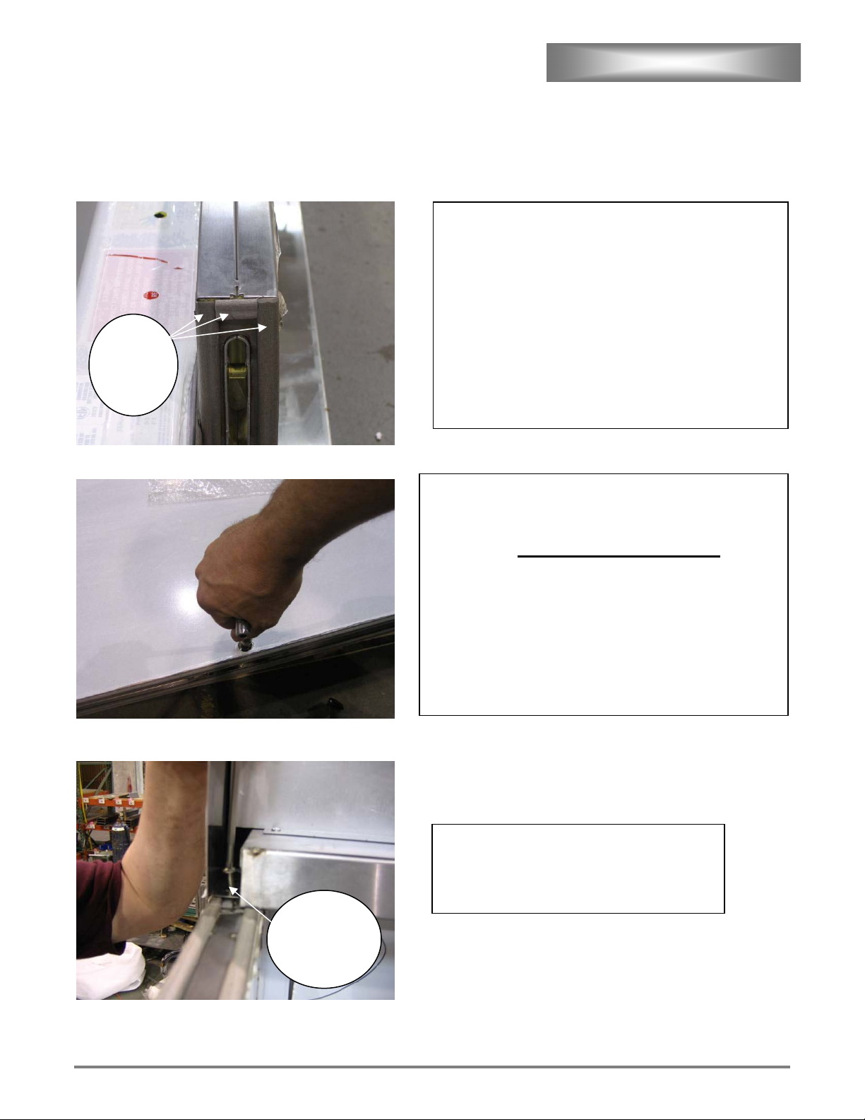
Note: When installing Panel
Assemblies inspect to insure gasket
material is installed along all edges.
Header panel requires gasket material as shown. If gasket
is missing moisture will migrate into panel sections.
All three sides pictured have grey gasket material
installed.
Screw
in top of
front
Gasket
on all
three
sides
ETL File E8138 Rev. B2006
15
ASSEMBLY CONT’D
Install Front Corner panel and tighten cams.
Note: Do not over tighten.
A positive click should be felt when cam is locked. If
cam will not click into locked position do not over
tighten. Lube cam and work until cam locks. See note
on previous page.
Flip front assembly over.
Reinstall screw in top of each front corner panel
securing valance.
Note: Check sides for gasket material on all sides!
Install one left and one right side to front. Place front with side panels into base track, then plumb front corners. To plumb place
level on front as pictured in center photo. Cams may need to be repositioned to achieve plumb. Shim (Part #155-249) front to
achieve level, left to right only. Shims, pictured below level, are provided with unit.
See Chart 1 on page 13 for correct panel placements. Continue to add side panels 90º in relation to ground. Keep the front
plumb and level. Shim sides as needed. Allow top of panels to be uneven if necessary to maintain to maintain 90 º angles from
ground. Drain holes on back corners go to bottom back of unit.
Shim Part # 155-249
ETL File E8138 Rev. B2006
16
ASSEMBLY CONT’D
Align front as necessary, then mark rear base channel
position.
Remove rear corners.
Note: Drain holes on back corners go to
bottom back as pictured.
Install remaining panel assemblies maintaining 90º
angles.
Drill holes with rotary drill and install anchors in rear base
channel. Drill 10MM diameter hole 1 ½” deep and remove
all dust from hole. Do not drill too deep. Install anchor with
provided insert tool.
Note: If concrete subfloor has additional
layer of softer leveling slag and anchors
do not hold, a longer anchor bolts may
be necessary.
Drain hole
always goes to
b
ottom
,
b
ac
k
ETL File E8138 Rev. B2006
17
ASSEMBLY CONT’D
Note: Make sure all hinge mounting
screws are tight.
Hang door(s). Use a 30”x 1”x 4” board (as shown) or a
dolly to lift door and move into position.
Make sure both hinges seat and hinge washers are
present.
Hinge
Washe
r
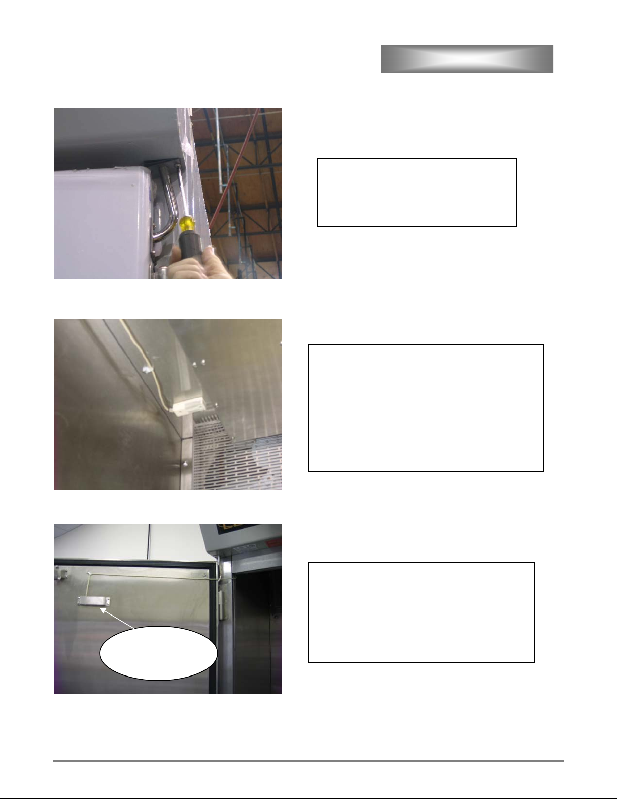
Temp/Humidity
Sensor flat side up
On model # LRP-2 sensor will come preinstalled inside
header.
On all models push connector end through hole in door
and connect to control as pictured.
Plug temperature / humidity sensor into board with flat
side of connector up as pictured.
Plug connectors from control panel into connectors from
door. Verify wire #’s on both sides of connector
correspond.
Check to assure all wires in connecter seat tightly
to
g
ether.
Screw control panel into door using supplied screws.
Bend tabs as necessary to align with center set of
holes.
Bezel may need to be bent slightly to create tight fit to
panel.
Install bezel as shown using supplied screws.
Optional: A small bead of silicone around bezel will
seal bezel.
ETL File E8138 Rev. B2006
18
ASSEMBLY CONT’D
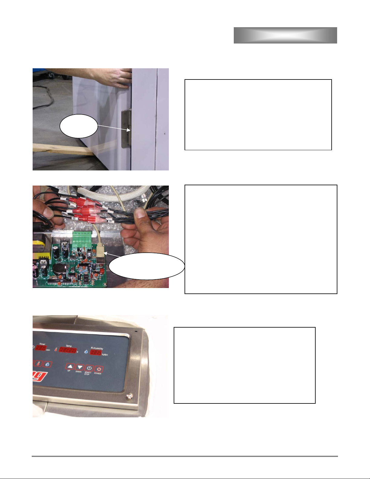
Install door, handles and bumpers onto
door(s).
Install conduit mounting brackets and
gaskets onto valance and door.
Install supplied cable retention clips to door and
inside corner of proofer with door open all the
way and no slack in cable.
Push remaining cable into door
Seal opening in the door with silicone.
To maximize airflow over sensor install sensor 2-3
inches in front of climatizer fan. If more than one
climatizer is utilized install sensor in front of
climatizer closest to controller.
Leave a small amount of slack in cable at sensor end.
Route cable towards hinge side of door and install
supplied cable retention clips keeping slack out of
cable.
Silicone opening
after sensor is
installed
ETL File E8138 Rev. B2006
19
ASSEMBLY CONT’D
Note: Inspect ceiling panels for gasket material on bottom.
Install ceiling panels flush with sides.
Align back corners and install one screw. Recheck door alignment and plumb of front. Shim front with part # 155-249 as
needed to obtain plumb.
Align ceiling panels flush with side and install
remaining 3” hex head ceiling screws.
Peel all vinyl from inside unit.
Fill cam holes with caulk and install plugs.
Check for gaps and caulk header to top seam
and all other
openings.
Note: If unit is a pass through leave out 2 upper
corner plugs in corner without climitizer;
instead, install stiffener plate Part #155-323 in
corners without climatizer installed. Stiffener
plate should join corner and header and be
secured with su
pp
lied stainless steel hardware.
ETL File E8138 Rev. B2006
20
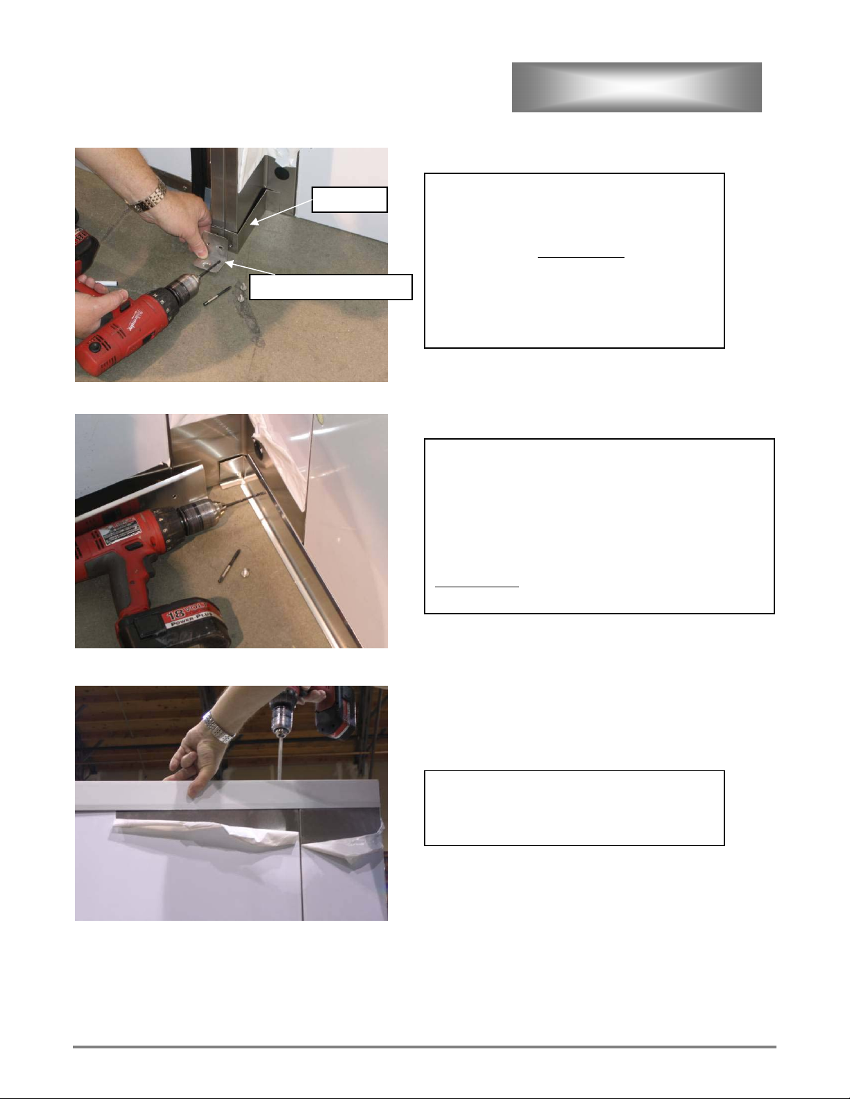
ASSEMBLY CONT’D
Install left and right jam trim, and anchor bracket
to unit. Drill and tap bracket mounting holes.
Shim if needed with 155-377-1.
Secure only with Stainless Steel screws
provided.
Anchor brackets to floor; see page 16 for anchor
instructions.
Caulk base channels to floor inside and out.
Install rear corners behind base molding.
Cut to fit and install base trim over corners.
Drill trim mounting holes with provided drill bit. Lube
holes and tap with provided tap. Secure with provided
Stainless Steel
machine screws.
Install top trim part #155-745 using provided
screws.
Do not over tighten.
155-377 anchor bracke
t
Jam Tri
m
ETL File E8138 Rev. B2006
21
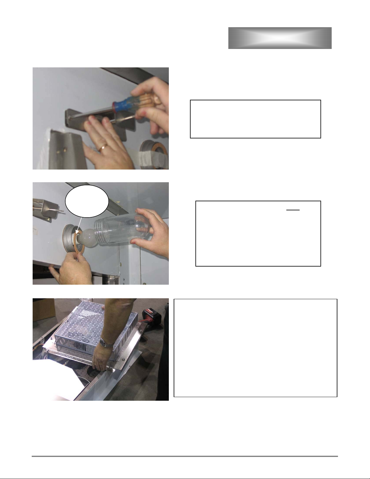
ASSEMBLY CONT’D
Apply caulk to backside of high limit mounting
bracket and install high limit and bracket.
On LRP1 and LRP2 models Install 250V light
bulb, gasket, and globe.
New LRP3 models will have Florescent Lamps
pre-installed.
Note: If 120V bulbs are
installed fuses will blow.
Remove fan guard, cover, and water line from air duct
assembly.
Determine duct location.
Single Door Proofers - Back wall tight to left side.
Double Door Proofers - Left side wall tight to front.
Double Duct Proofers - Mount first duct on left side wall tight
to front. Mount second duct on same side tight to back.
LRP3 Models – Ducts can be mounted on left or right side
determine by drain location.
Remove climatizer mounting screws from applicable corner.
Gasket
must be
installed
 Loading...