

LAVAZZA LB 2801, LB 2800, LB 2811, LB 2810 Maintenance Manual
LB 2800-2801-2810-2811
MAINTENANCE MANUAL FOR
TECHNICAL ASSISTANCE
MANUAL CODE 10066574 / REL. 2.00 / FEBRUARY 2012
LB 2800
Machine code
10080022
LB 2801
Machine code
110080118
LB 2810
Machine code
10080005
LB 2811
Machine code
10080023
Manual code
10066574
Rel. 2.00
Edition 02/2012
www.absoluteaftersales.it
© Copyright LAVAZZA S.p.A.
Tel. 00 39 .011.2348429
Fax 0039.011.23480466
technicalservice@lavazza.it
Certificated n° IT09/0445

Manual code 10066574 / Rel. 2.00 / February 2012
Maintenance manual for technical assistance
T
ABLE OF CONTENTS
1. GENERAL INFORMATIONI . . . . . . . . . . . . . . . . . 1
1.1. Structure of the manual . . . . . . . . . . . . . . . . . . 1
1.1.1. Scope and content . . . . . . . . . . . . . . . . . . . 1
1
.1.2. Messages used . . . . . . . . . . . . . . . . . . . . . . 1
1.1.3. Users . . . . . . . . . . . . . . . . . . . . . . . . . . . . . . 1
1.1.4. Preservation . . . . . . . . . . . . . . . . . . . . . . . . 1
1.2. Designated personnel . . . . . . . . . . . . . . . . . . . 1
1.3. Machine composition . . . . . . . . . . . . . . . . . . . . 2
1.3.1 Models . . . . . . . . . . . . . . . . . . . . . . . . . . . . . 2
1.3.2. Identification data . . . . . . . . . . . . . . . . . . . . . 3
1.3.3. Overall dimensions and weight . . . . . . . . . . 2
1.3.4. Technical specifications . . . . . . . . . . . . . . . 2
1.3.5. External components . . . . . . . . . . . . . . . . . 2
1.3.6. Internal components . . . . . . . . . . . . . . . . . . 3
1.3.6.1. Boiler . . . . . . . . . . . . . . . . . . . . . . . . . . . . . 3
1.3.6.2. Brewing unit . . . . . . . . . . . . . . . . . . . . . . . . 4
1.3.6.3. Automatic water entry system (A.E.A) . . . . 4
1.3.6.4. Flowmeter. . . . . . . . . . . . . . . . . . . . . . . . . . 5
1.3.6.5. Boiler temperature and pressure control . . 5
1.3.6.6. Pumping system. . . . . . . . . . . . . . . . . . . . . 5
1.3.6.7. Valve group . . . . . . . . . . . . . . . . . . . . . . . . 5
1.3.6.8. Electronic control unit . . . . . . . . . . . . . . . . 6
1.3.6.9. Softener . . . . . . . . . . . . . . . . . . . . . . . . . . 6
1.3.7. List of the accessories
supplied with the machine . . . . . . . . . . . . . . 6
2. GENERAL SAFETY STANDARD . . . . . . . . . . . . . 6
2.1. Stop functions . . . . . . . . . . . . . . . . . . . . . . . . . 7
2.2. Safety devices . . . . . . . . . . . . . . . . . . . . . . . . . 7
2.3. Residual risks . . . . . . . . . . . . . . . . . . . . . . . . . . 7
3. HANDLING AND STORAGE . . . . . . . . . . . . . . . . 8
3.1. Handling . . . . . . . . . . . . . . . . . . . . . . . . . . . . . . 8
3.2. Storage . . . . . . . . . . . . . . . . . . . . . . . . . . . . . . . 8
4. DISMANTLING AND DISPOSAL . . . . . . . . . . . . . 8
4.1. Instruction for end of life treatment . . . . . . . . . . 8
5. INSTALLATION AND START UP . . . . . . . . . . . . . 9
5
.1. Unpacking . . . . . . . . . . . . . . . . . . . . . . . . . . . . 9
5.2. Positioning . . . . . . . . . . . . . . . . . . . . . . . . . . . . 9
5.3. Water connection . . . . . . . . . . . . . . . . . . . . . . 10
5.4. Electric connection . . . . . . . . . . . . . . . . . . . . . 10
5.5. Start procedures . . . . . . . . . . . . . . . . . . . . . . . 11
6. RECOMMENDED TOOLS . . . . . . . . . . . . . . . . . 11
7. CONFIGURATION . . . . . . . . . . . . . . . . . . . . . . . 12
7.1. Machine alarms . . . . . . . . . . . . . . . . . . . . . . . 12
7.2. Programming . . . . . . . . . . . . . . . . . . . . . . . . . 12
7.2.1. Programming of coffee doses . . . . . . . . . . 12
7.2.2. Programming of cappuccino doses
(only LB 2800-LB 2810 models) . . . . . . . . 12
7.2.3 Hot water dispensing . . . . . . . . . . . . . . . . 13
7.2.4. Programming of coffee-cappuccino
sequence (only LB 2800-LB 2810 models) . 13
7.2.5. Loading of default data . . . . . . . . . . . . . . . 14
7.2.6. Boiler temperature programming . . . . . . . . 14
7.2.7. Dispensing coffee . . . . . . . . . . . . . . . . . . . 14
7.2.8. Preparation of hot drinks . . . . . . . . . . . . . . 15
7.2.9. Cappuccinatore (only LB 2800-LB 2810
models) . . . . . . . . . . . . . . . . . . . . . . . . . . . 16
7.2.10.Preparing coffee with milk . . . . . . . . . . . . . 16
8. DIAGRAMS . . . . . . . . . . . . . . . . . . . . . . . . . . . . . 17
8.1. Electrical diagram . . . . . . . . . . . . . . . . . . . . . . 17
8.2. Hydraulic diagram . . . . . . . . . . . . . . . . . . . . . 18
9. INSPECTIONS AND MAINTENANCE . . . . . . . . . 19
9.1. Periodic inspections . . . . . . . . . . . . . . . . . . . . 19
9.2. Routine and supplementary maintenance . . . 19
9.2.1. Brewing unit . . . . . . . . . . . . . . . . . . . . . . . 19
9.2.2. Discharge-one-way valve . . . . . . . . . . . . . 19
9.2.3. Replacing the perforator . . . . . . . . . . . . . . 20
9.3. Cleaning . . . . . . . . . . . . . . . . . . . . . . . . . . . . . 20

IV
Manual code 10066574 / Rel. 2.00 / February 2012
Maintenance manual for technical assistance
9.3.1. Cappuccinatore (only LB 2800 - LB 2810
m
odels) . . . . . . . . . . . . . . . . . . . . . . . . . . . 20
9.3.2. Capsule-holder . . . . . . . . . . . . . . . . . . . . . 21
9.3.3. Steam pipe (only LB 2800 - LB 2810
models) . . . . . . . . . . . . . . . . . . . . . . . . . . . 21
9.3.4. Body . . . . . . . . . . . . . . . . . . . . . . . . . . . . . 21
9
.3.5. Steam pipe end (only LB 2800 – LB 2810
models) . . . . . . . . . . . . . . . . . . . . . . . . . . . 21
9.3.6. Brewing unit . . . . . . . . . . . . . . . . . . . . . . . 21
10. TROUBLESHOOTING . . . . . . . . . . . . . . . . . . . 22
10.1. Signalling and solutions to the most common
problems . . . . . . . . . . . . . . . . . . . . . . . . . . . . 22
Manual code 10066574 / Rel. 2.00 / February 2012
1
Maintenance manual for technical assistance
1
. GENERAL INFORMATION
1.1. Structure of the manual
Before any operation is carried out on the machine,the
maintenance technician must carefully read the instruct
ions contained in this publication. The undertaking of
any operation on the machine, without having read and
understood the contents of this manual is prohibited. If
there is any doubt about the correct interpretation of the
i
nstructions, contact Lavazza in order to obtain the necessary clarification.
1.1.1. Scope and content
This manual contains all the information necessary for
the maintenance of the machine, safety instructions,
troubleshooting and diagrams.
All reproduction rights for the present manual are reserved to Luigi Lavazza S.p.A. The reproduction, even partial, of text or images is forbidden. Information contained
here cannot be transmitted to any third parties without
the prior written permission of Lavazza, which has the
exclusive rights to the property.
Lavazza reserves the right to modify features of equipments presented in this publication without prior notice;
it also declines any responsibilities for possible inaccurancies due to misprint.
It is recommended that the Internet site of the Lavazza
Technical Service be checked (at the following address
http://ts.inlavazza.it) to ensure that your manual is the
most recent version available and otherwise to download
an updated copy.
1.1.2. Messages used
Attention
ATTENTION messages indicate a danger, possibly
lethal, for the technician. The operations described
after this message must be carried out carefully and
safely using the personal protective equipment.
Warning
WARNING messages are displayed before procedures that, if not observed, could cause damage to the
machine.
Environment
ENVIRONMENT messages are displayed before procedures that, if not observed, could cause damage
to the environment.
Note
NOTE messages show further information useful for
the maintenance technician.
1.1.3. Users
This manual is designed for technicians qualified to
maintain the machine. Lavazza is not responsible for
damage derived from the failure to follow these rules.
1.1.4. Preservation
In order to be able to guarantee the integrity and utility of
t
his manual the following guidelines should be observed:
- employ this manual in such a way that it remains undamaged and whole;
- do not for any reason, remove, tear, or write over any
part of the manual;
- keep the manual in an area protected from humidity and
heat, in such a way that the quality and legibility of the
publication are not compromised;
- keep the manual close at hand for maintenance staff.
Warning
If this manual is damaged or lost, it is possible to
download another copy from the Lavazza Technical
Service site at the following address: http://ts.inlavazza.it.
1.2. Designated personnel
The machine may be operated only by a qualified technician who has read this manual and moreover who:
- has specific experience in the maintenance of professional coffee machines;
- is able to carry out repairs in case of serious malfunction of the machine / machines shown in this manual;
- is able to understand the technical contents of the manual and to correctly interpret drawings and diagrams
and has knowledge of the safety information described
below;
- has knowledge of the appropriate hygiene, workplace
safety, technology and security measures;
- knows how to act in an emergency, where to find the
personal protective equipment and knows how to use
it.
1
.3. Machine composition
If not expressly indicated in the text, the position numbers of the machine components refer to figures in the
chapters 1.3.5. External components and 1.3.6 Internal
components.
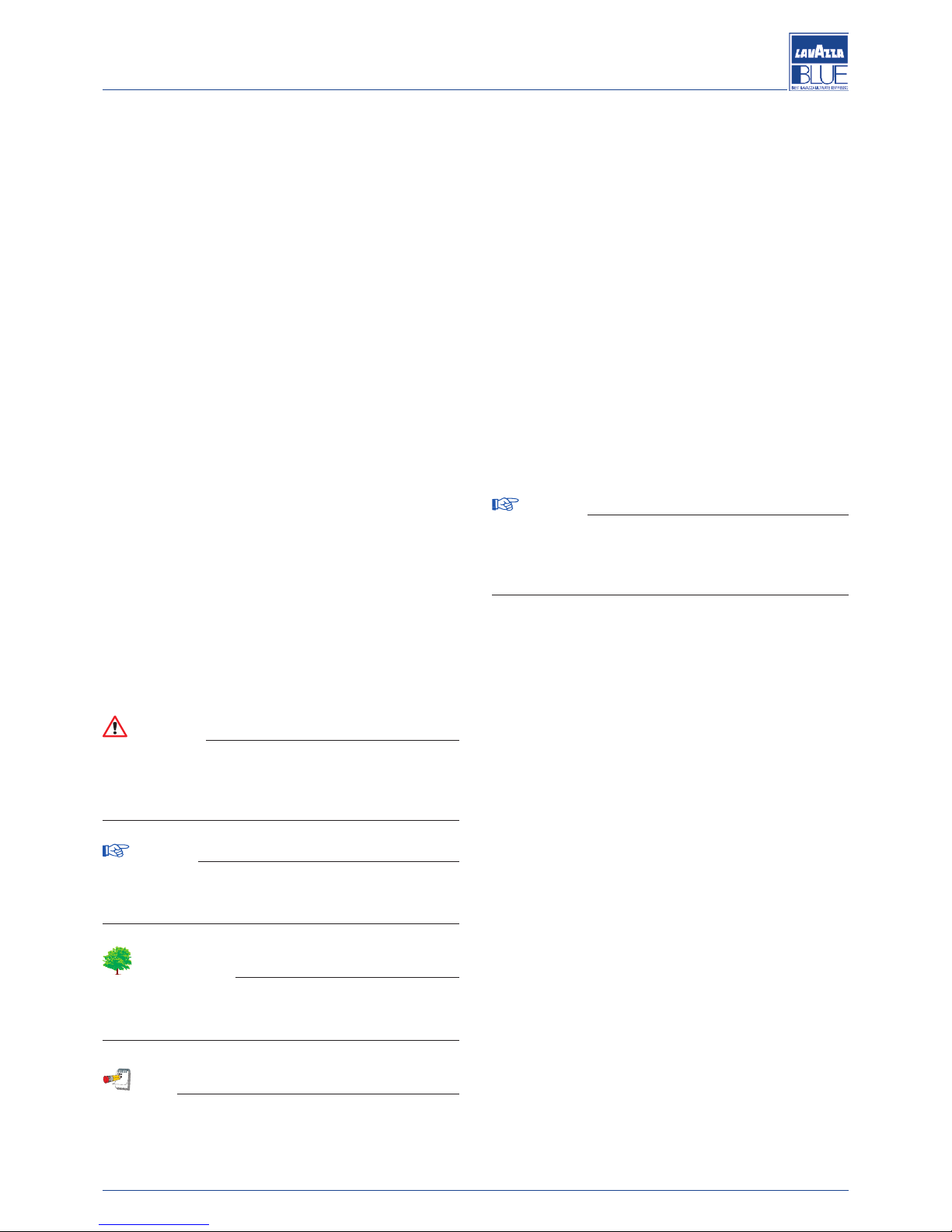
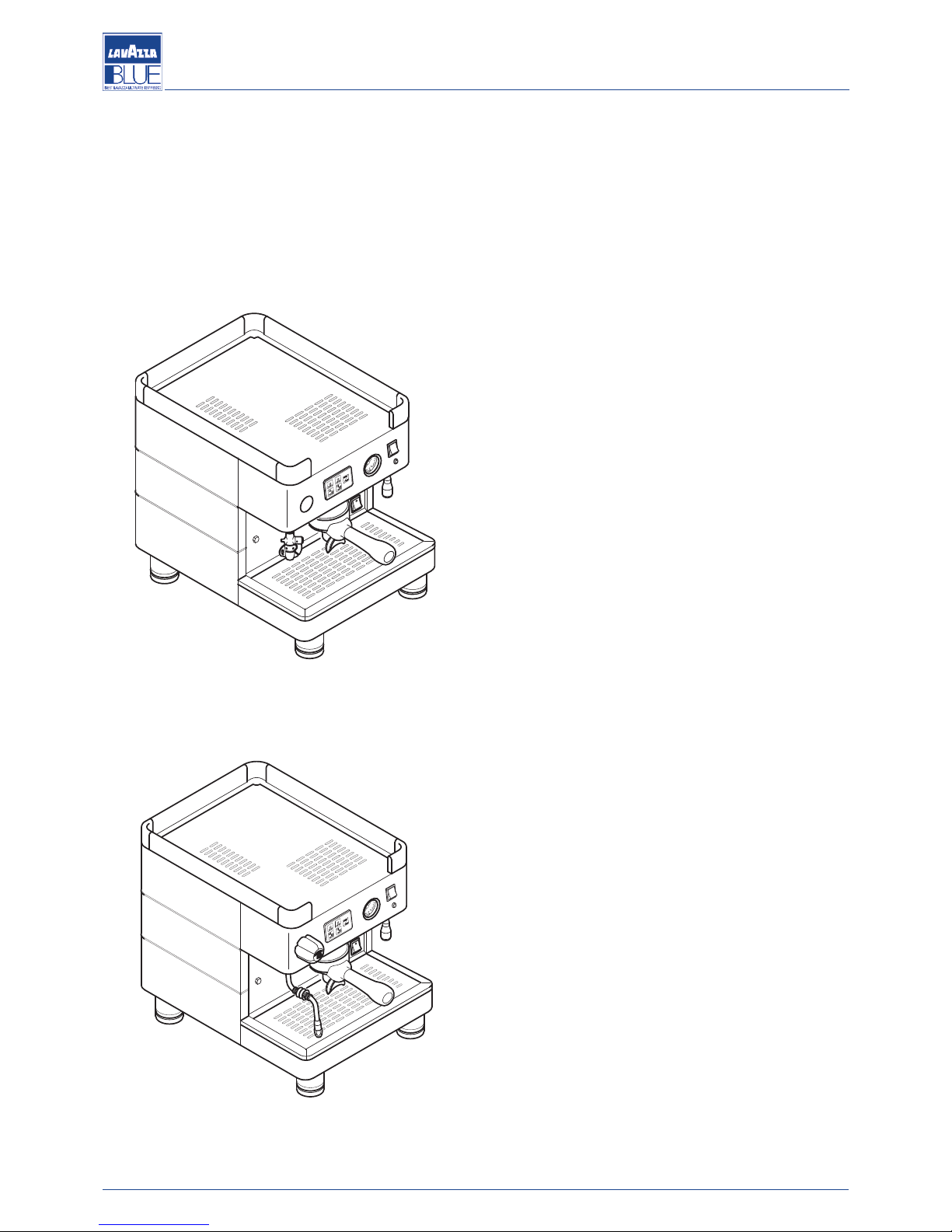
1.3.1. Models
LB 2800 - LB 2810
LB 2801 - LB 2811
1.3.2. Identification data
In the plate the following data of the machine are indicated:
- manufacturer;
- machine model;
- serial number;
-
Lavazza’s product code;
- date of manufacture;
- power supply voltage (V) and frequency (Hz);
- absorbed power (W);
- water mains pressure (MPa).
1.3.3. Overall dimensions and weight
Depth: 435 mm
Width: 322 mm
Height: 470 mm
Weight: 31 kg
1.3.4. Technical specifications
Power supply frequency: 50/60
Boiler capacity (litres): 2
Boiler pressure (bar): 1,4 max
Safety valve calibration (bar): 2
Supply water pressure (bar): 0 - 5 max
Coffee brewing pressure (bar): 8 - 9 max
LB 2800 - LB 2810
Power supply voltage (V): 230
Power consumption (W): 1700
LB 2801 - LB 2811
Power supply voltage (V): 120
Power consumption (W): 1350
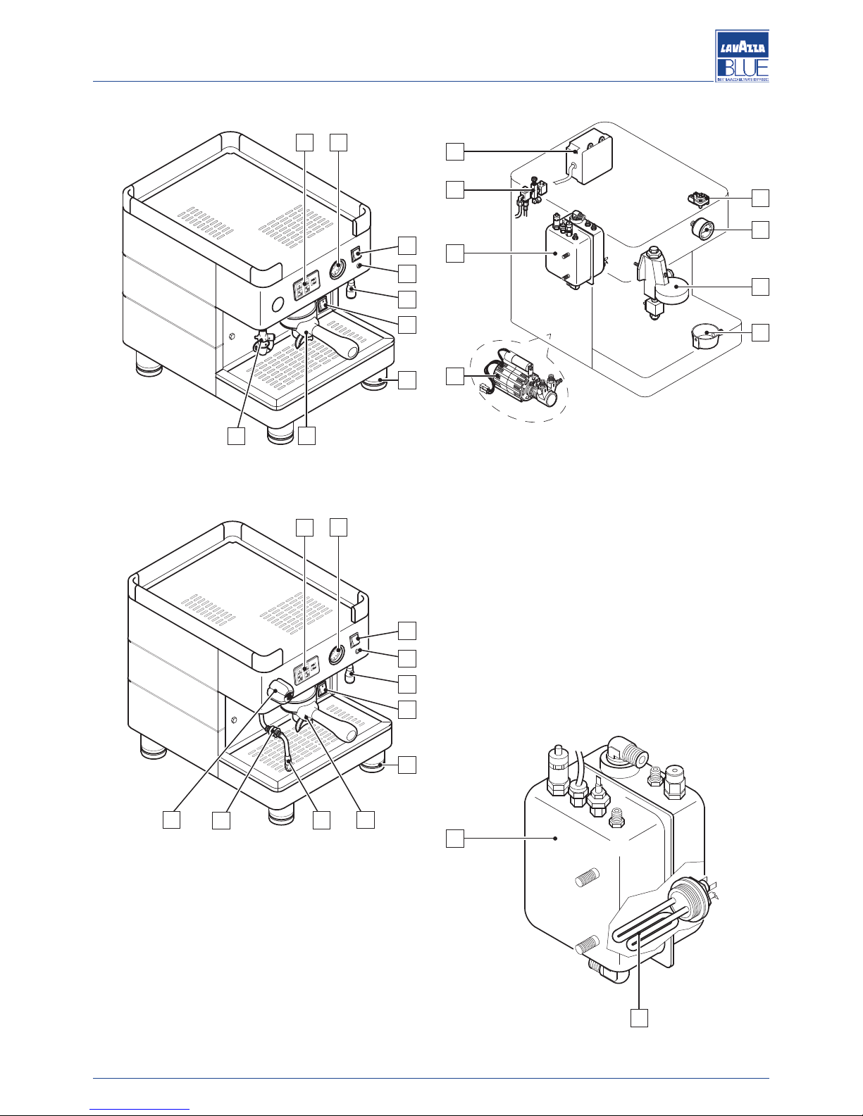
1.3.5. External components
1) Hot water dispensing key
2) Pilot light for boiler heater on
3) Boiler pressure gauge
4) Hot water pipe
5) On/off switch
6) Adjustable foot
7) Coffee spout
8) Keyboard
9) Cappuccinatore
10) Steam pipe
11) Rubber piece
12) Steam knob
55
22
2
2
55
22
22
2
Manual code 10066574 / Rel. 2.00 / February 2012
Maintenance manual for technical assistance
LB 2800 - LB 2810
LB 2801 - LB 2811
1.3.6. Internal components
13) Boiler
14) Control unit
15) Flowmeter
16) Boiler pressure gauge
17) Brewing unit
18) Drain tray
19) Internal power pump
20) Cold water mixer valve
1.3.6.1. Boiler
The boiler (A) is constructed of steel. A heat exchanger
connected to the brewing unit is attached to the boiler.
Water for coffee brewing is taken directly from the heat
exchanger. During brewing, cold water is sent inside of
the exchanger by the pump.
Inside the heat exchanger, cold water and the pre-existing hot water are mixed, thus obtaining optimal water
temperature for coffee infusion. The water is heated into
the boiler by an electrical heating element immersed in
the water (B).
55
22
2
2
55
22
2
2
1
2
4
3
6
8
5
7
9
1
2
4
3
6
8
5
7
11
10
12
16
15
13
14
20
19
18
17
A
B
Manual code 10066574 / Rel. 2.00 / February 2012
3
Maintenance manual for technical assistance
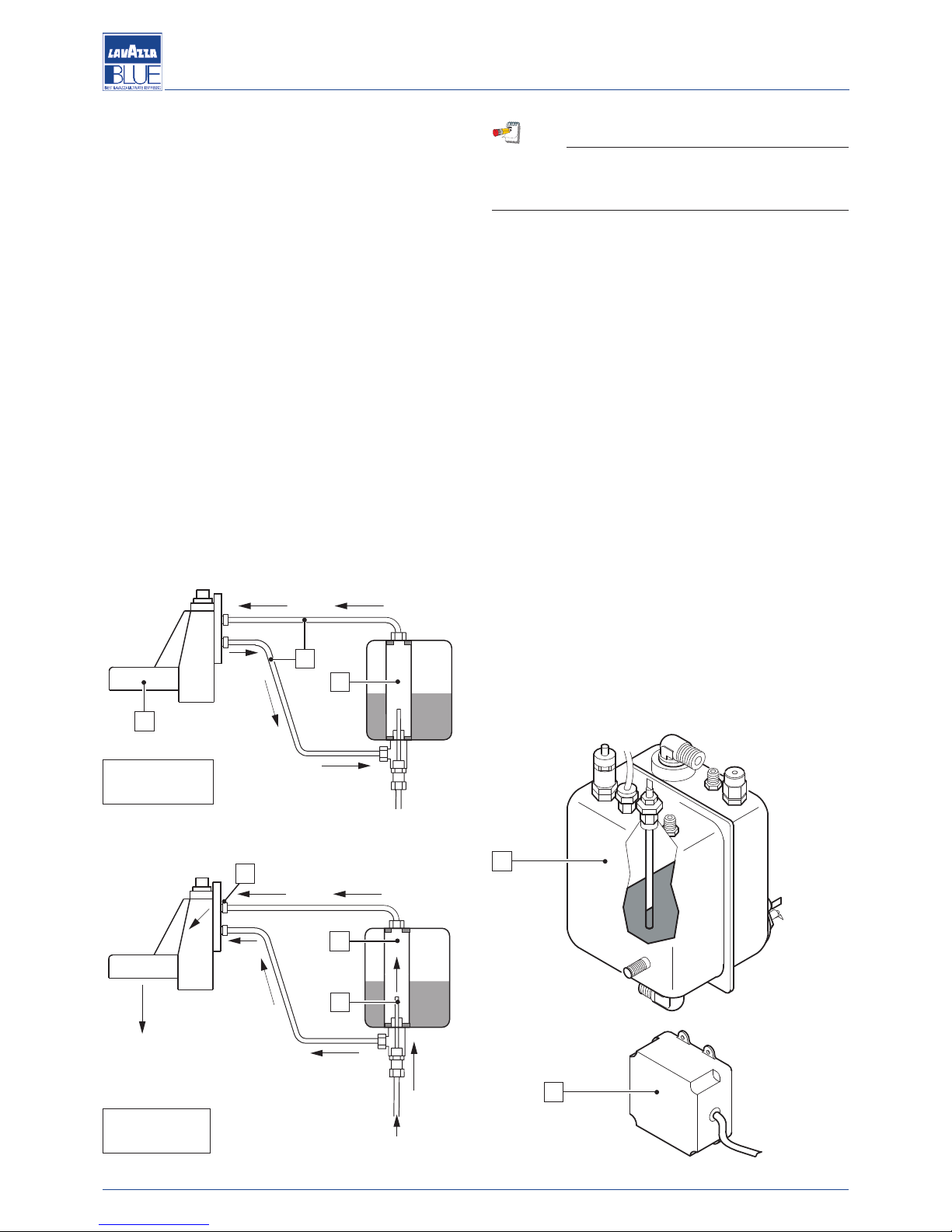
1.3.6.2. Brewing unit
The brewing unit and the heat exchanger are fundamental components to obtain espresso coffee.
Specifically the function of the unit is coffee dispensing.
In this system the brewing unit (1) is heated by a therm
osiphon circuit (2) connected to the heat exchanger
(3). The same water is used for coffee brewing:
- activation of the solenoid valve and the pump allows
cold water to enter the exchanger (3) via the injector
(4);
- heated water is carried to the unit (1) for brewing from
the exchanger (3);
- the pump allows water pressure to be increased up to
8-9 bar for brewing.
In order to increase or decrease the temperature of the
coffee in the cup, water temperature in the boiler must
be changed (see section 6.3.11).
N
ote
I
f the water temperature in the boiler is decreased
but the coffee is still too hot, the reducer (5) supplied
with the machine must be put on the pipe.
1
.3.6.3. Automatic water entry system (A.E.A)
The automatic water entry system checks the water level
in the boiler.
The system is composed of:
- a probe inserted in the boiler (A) which is composed
of a stainless steel rod;
- an electronic control unit (B);
- a pump that, with the AEA solenoid valve, allows the
water flow into the boiler;
- a AEA solenoid valve.
The electronic control unit controls the level of the water
in the boiler.
When this level drops the contact with the probe is interrupted; the control unit sends an impulse to the inlet
solenoid valve and the power pump, which restore the
normal level of water in the boiler.
To avoid possible flooding due to machine malfunctions
or leaks in the water circuit, the electronic control unit is
equipped with a timing device that cuts off the automatic filling after a maximum period of 120 seconds.
3
2
1
Water inlet
Coffee
dispensing
3
4
5
A
B
At resting
position
During
dispensing
4
Manual code 10066574 / Rel. 2.00 / February 2012
Maintenance manual for technical assistance
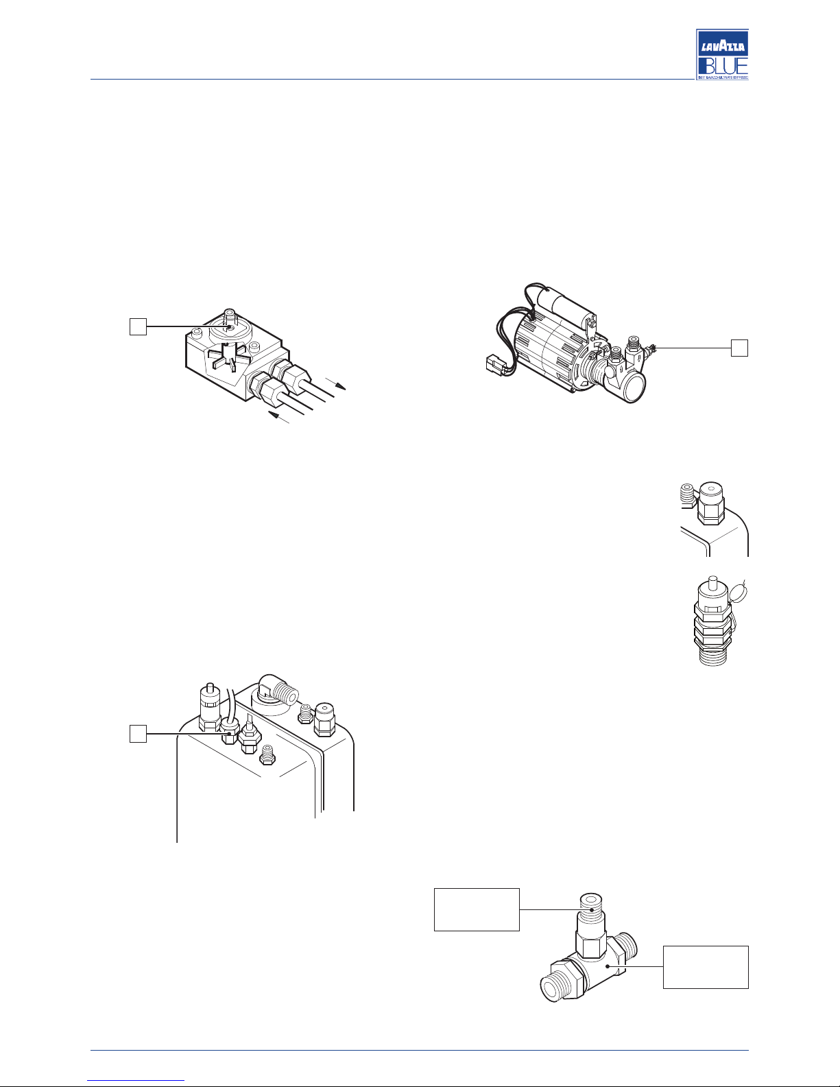
1.3.6.4. Flowmeter
The flowmeter installed on the EVD electronic machines,
measures the quantity of water sent to the brewing unit
for espresso brewing.
The flowmeter generates an electric impulse which is
sent to the electronic control unit.
This impulse is read by the control unit and memorized
d
uring the programming of the dose.
The flashing of the LED (1) indicates that the electrical
impulse has been sent from the flowmeter to the control
unit.
1.3.6.5. Boiler temperature and pressure control
The flowmeter installed on the EVD electronic machines,
measures the quantity of water sent to the brewing unit
for espresso brewing.
The flowmeter generates an electric impulse which is
sent to the electronic control unit.
This impulse is read by the control unit and memorized
during the programming of the dose.
The flashing of the LED (1) indicates that the electrical
impulse has been sent from the flowmeter to the control
unit.
1.3.6.6. Pumping system
It is the component that feeds the machine, raising the
water pressure to 8-9 bars for coffee brewing and automatic filling of the boiler.
To set the pressure rating, proceed as follows:
- select a coffee dispensing key;
- connect a pressure gauge, with bottom scale greater
than 9 bars, to the specific fitting on the water circuit
(see the hydraulic diagram);
-
set the pressure by using the pressure adjusting screw
located in the pump (A) in such a way as to reach a
value between 8 and 9 bars: turning clockwise the
pressure increases, turning anticlockwise the pressure
d
ecreases;
- check the pressure on the pressure gauge.
1.3.6.7. Valve group
The valves serve to ensure safety and proper machine
operation.
Safety valve
The safety valve serves to eliminate the air
in the boiler during the heating of the machine.
Pressure relief valve
The pressure relief valve ensures that the
pressure in the boiler doesn’t exceed 2.2
bars. In case of a malfunction, the capacity
of the valve is likely to eliminate all the excess pressure in the boiler.
Expansion – one-way valve
This device consists of an expansion valve and a oneway valve.
Expansion valve: the cold water sent from the pump to
the heat exchangers is heated. This heating causes an
increase in the volume of the water. To limit pressure increases in the hydraulic circuit, the valve limits the maximum internal pressure in the circuit to 12 bars.
one-way valve: its function is to prevent the backflow of
the water from the exchangers to the hydraulic circuit.
1
X
A
One-way
valve
Expansion
valve
Manual code 10066574 / Rel. 2.00 / February 2012
5
Maintenance manual for technical assistance
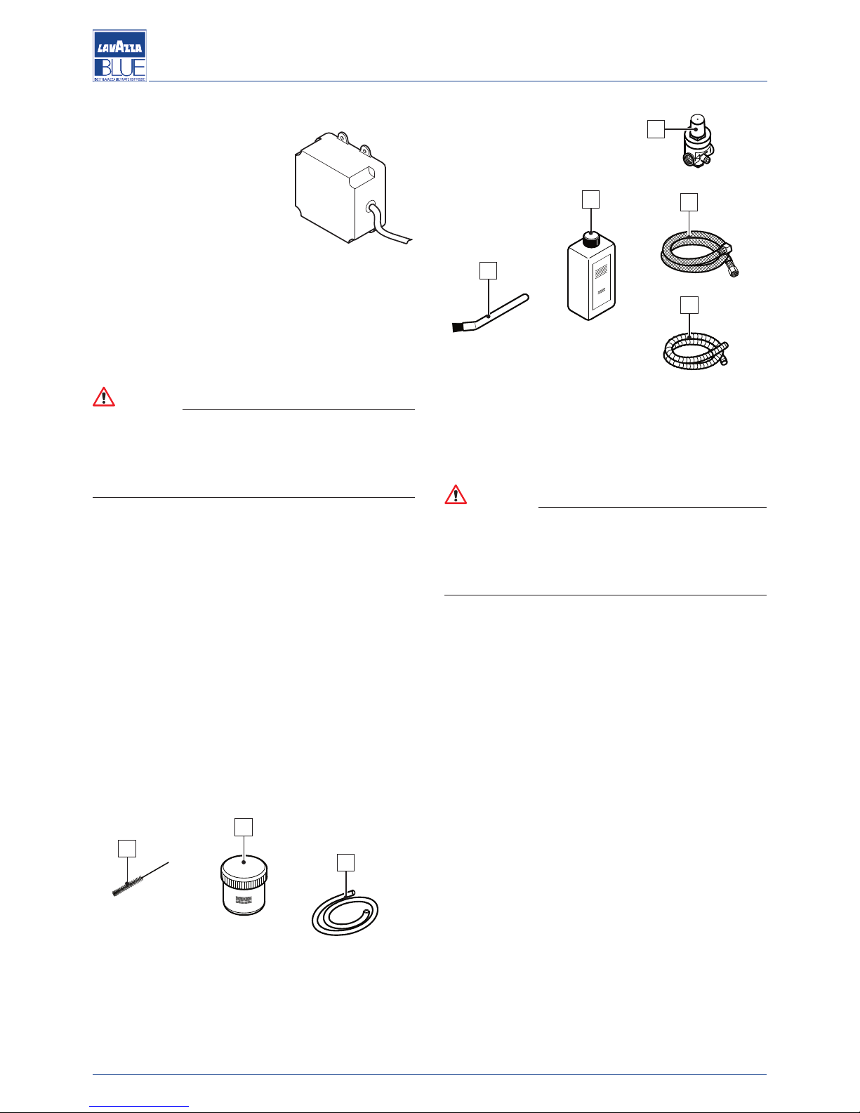
1.3.6.8. Electronic control unit
This unit electronically controls
the coffee dose via the water
flow in the flowmeter and the boiler water filling. It also manages
the operation of the automatic
cappuccinatore. This control unit
c
an be connected to counter systems of the dispensing cycles
via a special interface device.
1.3.6.9. Softener
Tap water contains insoluble salts, which causes buildup of lime scale in the boiler and in other parts of the machine. The softener eliminates or greatly reduces the
presence of these mineral salts.
Attention
The lime scale build-up in the water circuit and boiler prevents the heat exchange and affects the efficient working of the machine. If the boiler is
encrusted with lime scale this may stop the machine
for long periods and therefore void any guarantee.
1.3.7. List of the accessories supplied with the
machine
Booklet: instructions for using the machine.
Accessories:
A) Rifle-type brush
B) Brush with bristles
C Detergent for cappuccinatore
D) Puly caf
E) Silicone pipe
F) Cavoflex pipe
G) Flexible pipe
H) Reducer
2. GENERAL SAFETY STANDARD
Attention
Failure to comply with basic safety rules and precautions could cause accidents during machine
operation and maintenance. During the repair of the
machine all the measures necessary to prevent accident must be used.
The main safety precautions that should be used when
operating the machine are described below. Lavazza
does not foresee every possible situation that could be
potentially dangerous. Warnings in this manual are not
exhaustive. If tools, procedures, working methods or techniques not expressly recommended are used, make
sure that there is no risk of personal injury or injury for
other people.
Adjustments, specifications and illustrations in this manual are based on information available at the moment
of the editing and therefore can change anytime. These
modifications affect maintenance operations to be carried out. Ensure that the updated version of the present
manual is being used.
Power connection must be made in compliance with the
CEI EN 60335-1 and local safety standards in force.
The electric socket connecting the machine must:
- conform with the type of plug installed on the machine,
if it is present;
- be sized in order to comply with the data provided on
the plate on the bottom of the appliance;
- be connected to ground system, efficient and in accordance with the law.
H
B
C
G
F
E
D
A
6
Manual code 10066574 / Rel. 2.00 / February 2012
Maintenance manual for technical assistance
 Loading...