


Table of contents
1General information
2Electrical diagram
3Hydraulic diagram
4Maintenance schedules
Maintenance manual for technical assistance |
TECHNICAL ASSISTANCE |
LB 1000 BLUE FAMILY |
|
Machine code: 80601 |
Tel. 0039 011 2398429 |
Handbook code: 83346 |
Fax 0039 011 23980466 |
Revision: September 2004 |
E-mail: assistenzada@lavazza.it |
Rel: 1.00 |
|
|
|
Use only original spare parts
The manufacturer declines all responsibility if non original spare parts are used
|
“ |
© Copyright LUIGI LAVAZZA S.p.A |
|
|
|
||
“ |
|
“LB 1000 BLUE FAMILY” |
COD. 83346 / REL. 1.00 / SEPTEMBER 2004 |
|
|
|
|

1
General information
1/6
•Preface
•Safety information
•Safety specifications
•Residual risks
•Environmental conditions allowed
•Warehousing
•Scrapping
•Transport
•List of tools necessary for maintenance
|
|
“LB 1000 BLUE FAMILY” |
COD. 83346 / REL. 1.00 / SEPTEMBER 2004 |

1
General information
2/6
Preface
This manual contains information, safety instructions, spare parts and wiring diagrams to carry out the correct maintenance and to solve eventual problems. All rights reserved by Lavazza S.p.A. including the rights to reproduce the text and images of this document or part of it.
The continuous development and improvement of the machine may have caused modifications that are not included in this manual. Read it carefully and keep it at hand for reference.
Before leaving the factory this specific machine's model has been submitted to a strict control in order to guarantee reliability; therefore you should verify that during transportation the dispenser has not incurred structural damages that could compromise its operation and safety.
Some items illustrated in the figures of this manual could be different of those on the machine; some components may be omitted to obtain illustrations.
Keep this manual in an accessible place near maintenance staff.
|
|
“LB 1000 BLUE FAMILY” |
COD. 83346 / REL. 1.00 / SEPTEMBER 2004 |

1
General information
3/6
Safety information
Failure to comply with basic safety rules and precautions could cause accidents during machine operation, maintenance and repair. An accident can often be avoided by recognising potential hazardous situations before they occur. The operator has to pay attention to potential hazards and have training, competences and correct tools to carry out these tasks properly.
The improper use of the machine either during operation or maintenance could be dangerous and cause serious accidents.
Do not operate the machine or carry out maintenance until these instructions have been read and understood.
Safety precautions and warnings are given in this manual and indicated on the machine. If the operator does not pay attention to these warnings he could have an accident with serious consequences for himself and others.
Lavazza S.p.A. does not foresee every possible situation that could be potentially dangerous.
The warnings in this manual and on the machine are not exhaustive.
If tools, procedures, working methods or techniques not expressly recommended by Lavazza S.p.A. are used, make sure that there is no risk of personal injury or injury for other people.
Information, specifications and illustrations of this manual are based on the information available at the moment of editing. Specifications, adjustments, illustrations and other items can change anytime and these modifications can influence the maintenance operation to be performed.
Use only original spare parts
The manufacturer declines any responsibility for the use of uncertified spare parts.
|
|
“LB 1000 BLUE FAMILY” |
COD. 83346 / REL. 1.00 / SEPTEMBER 2004 |

1
General information
4/6
Safety specifications
The following indications cannot completely protect from all dangers which could be incurred while operating the “LB 1000” machine, good sense should be used at all times and only experienced personnel should carry out maintenance, along with measures to prevent accident.
In each section ulterior safety specific prescriptions for different operations are described.
Do not operate the machine or perform ordinary maintenance before having read and understood the instructions in the present manual.
Do not plug the machine into an outlet with a voltage different from that indicated on the label on the bottom of the machine.
Some components of the machine operate at the net tension.
Do not touch electric wires, switches, push buttons etc... with wet hands.
Before proceeding with processing or intervention not scheduled, performed following a different procedure from that one indicated in the manual, consult
Lavazza technical assistance.
Do not position “LB 1000” machine in corrosive or explosive environment or exposed to the atmospheric agents.
Keep the “LB 1000” machine free from extraneous material such as deposits, tools and other objects that could damage the operation and cause harm to people.
Avoid the use of inflammable or toxic solvents, benzene compounds, ether and alcohol for cleaning.
Always keep the manual near authorized maintenance personnel, so that it can be consulted in case of need.
If this manual is lost or damaged, Lavazza will provide a copy.
Structural damages, modifications, tamperings, alterations or improper repairs could compromise the safety of the “LB 1000” machine, this will negate any certification.
Any modifications should be performed exclusively by Lavazza technicians.
Residual risks
The accurate analysis of the risks provided by Lavazza and filed in the technical dossier, has eliminated most of risks related with the use and maintenance of the machine. The users shouls remember to strictly follow the instructions, procedures and recommendations contained in this manual and the safety rules in force, including the use of the protection devices, both integrated in the machine and individual.
|
|
“LB 1000 BLUE FAMILY” |
COD. 83346 / REL. 1.00 / SEPTEMBER 2004 |
1
General information
5/6
Environmental conditions allowed
To guarantee its correct operation, the “LB 1000” machine must be positioned in a place protected from atmospheric agents (rain, hail, snow, fog, dust etc...) with an environmental temperature between 0°C and 32 °C and with relative damp not above 70%.
The working environment must be clean, sufficiently bright and free from explosive or corrosive atmosphere.
Storage / Warehousing
Store the “LB 1000” machine in a place protected from atmospheric agents with temperatures between 0°C and 40°C, possibly in the original packing or by protecting it with nylon sheets to avoid the accumulation of dust.
Demolition / Scrapping
The demolition happens at the end of the working cycle of the machine that in normal conditions of use and maintenance should last more than 10 years.
In case of demolition all the components must be disposed in appropriate dumps following the law in force. Before demolition it is necessary to separate the different parts (plastics or rubber, electric and electronic material etc...).
The section made of plastic, aluminium and steel material may be recycled..
Transport
Loading and unloading operations and in general all handling operation of the
“LB 1000” machine must be done with extreme care. For occasional transport use the original packaging, which will contain and protect the machine.
|
|
“LB 1000 BLUE FAMILY” |
COD. 83346 / REL. 1.00 / SEPTEMBER 2004 |

1
General information
6/6
List of tools necessary for maintenance
1 |
3 mm Hexagonal |
2 |
Tamper torx t10 |
3 |
Long nose pliers. |
4 |
Small flat-tip |
|
key. |
screwdriver. |
|||||||
|
|
recess male key. |
|
|
|
|||
5 |
Plastic hammer; |
6 |
12 mm spanner; |
7 |
15 mm spanner; |
8 |
Cross tip |
|
screwdriver ph2; |
||||||||
|
|
|
|
|
|
|
||
9 |
14 mm spanner; |
10 |
8 mm socket |
11 |
5 mm Hexagonal |
12 |
Large flat-tip |
|
|
|
|
spanner; |
|
key; |
|
screwdriver; |
|
13 |
Pliers for seeger |
14 |
Flat cotter-key |
15 |
7 mm Hexagonal |
16 |
5.5 mm spanner. |
|
ring; |
pusher; |
socket spanner; |
||||||
“LB 1000 BLUE FAMILY” |
|
|
|
COD. 83346 / REL. 1.00 / SEPTEMBER 2004 |
||||
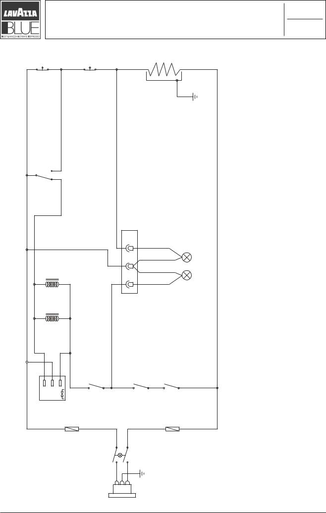
Wiring diagram
T 1 |
T 2 |
|
|
R 1 |
M 4 |
|
|
|
|
|
|
|
CN 1 |
|
|
|
|
|
L 2 |
P2 |
|
|
|
L 1 |
P1 |
|
|
|
|
|
M 1 |
|
M 2 |
M 3 |
Board |
|
|
|
|
TMF |
main |
F |
N |
TMF |
|
Luminous |
switch |
|
|
|
|
gulp raeR |
|
|
“LB 1000 BLUE FAMILY” |
|
|
|
|
2
1/1
L1=GREENLEDMACHINEREADY“LIGHTED” |
L2=ORANGELEDMACHINEINTEMPERATURE“LIGHTED” |
R1=RESISTANCE |
Cn1=CONNECTORS |
|
|
FUSE |
|
PUMPCONTROL |
USEDCAPSULES |
COVER |
STEAM |
TMF=SAFETYTHERMAL |
T1-2=THERMOSTATS |
M1=MICROSWITCHFOR |
M2=MICROSWITCHFOR |
M3=MICROSWITCHFOR |
M4=MICROSWITCHFOR |
COD. 83346 / REL. 1.00 / SEPTEMBER 2004

3
Hydraulic diagram
1/1
Heating unit
Coffee
|
Steam |
|
|
|
|
|
|
Steam valve |
|
Cylinder |
|
|
|
|
|
|
|
Coffee position |
knob |
Open |
|
Close |
|
Coffee valve |
Quick-release |
“0” position |
knob |
Close Close |
|
Open Open |
|
Steam position |
knob |
|
|
||||
“Cof” pos. |
|
|
|
Coffee |
valve |
Steam |
valve |
“Steam”pos. |
|
|
|
|
|
|
|
Dispenser
Air |
Water |
Vibrationdamping unit |
Pump |
Filter |
Air |
Water |
Vibrationdamping unit |
Water tank |
|
|
|
Pump |
|
|
|
|
|
|
|
“LB 1000 BLUE FAMILY” |
COD. 83346 / REL. 1.00 / SEPTEMBER 2004 |
Index of maintenance sheets
4.1Preliminary operations of case maintenance
4.2Hydraulic section maintenance
4.3Electric section maintenance
4.4Heating unit maintenance
4.5Piston unit maintenance
4.6Board frame maintenance
4.7Frame maintenance
4.8Micro switch maintenance
4.9Base maintenance
4
1/1
|
|
“LB 1000 BLUE FAMILY” |
COD. 83346 / REL. 1.00 / SEPTEMBER 2004 |

Preliminary operations of |
|
4.1 |
|
|
|
||||
case maintenance |
|
|
|
|
|
1/9 |
|
||
|
|
|
||
|
|
|
|
|
A
CAUTION
Remove plug from power outlet before any
!maintenance operations!
Never start the machine during maintenance operations.
Slide and remove the water tank, hold from the cover “A” and pull upward
Remove the drop and capsule drawer, catch on the rear side “A” and pull to the external side.
|
|
“LB 1000 BLUE FAMILY” |
COD. 83346 / REL. 1.00 / SEPTEMBER 2004 |
Preliminary operations of |
|
4.1 |
|
|
|
||||
case maintenance |
|
|
|
|
|
2/9 |
|
||
|
|
|
||
|
|
|
|
|
1 |
A |
|

 B
B
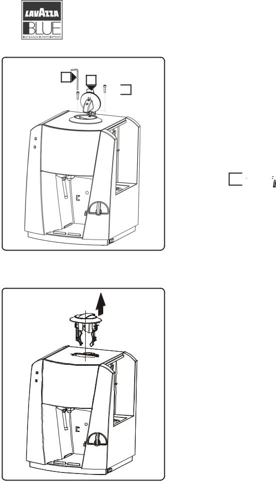
Open the capsule inserting cover “A” and by means of the key “1” unscrew the two fixing screws “B”.
1 


Remove by pulling up the entire capsule inserting unit.
|
|
“LB 1000 BLUE FAMILY” |
COD. 83346 / REL. 1.00 / SEPTEMBER 2004 |

Preliminary operations of |
|
4.1 |
|
|
|
||||
case maintenance |
|
|
|
|
|
3/9 |
|
||
|
|
|
||
|
|
|
|
|
2
Unscrew the 4 screws which fix the upper panel by torx t10 key “2”.
2
A
Remove the upper panel “A” from the seat of the capsule inserting unit and with a light traction pull to the machine rear following the arrow in such a way as to release it from the frame.
|
|
“LB 1000 BLUE FAMILY” |
COD. 83346 / REL. 1.00 / SEPTEMBER 2004 |

Preliminary operations of |
|
4.1 |
|
|
|
||||
case maintenance |
|
|
|
|
|
4/9 |
|
||
|
|
|
||
|
|
|
|
|
Disconnect the earthing cable “A” from the male faston terminal on the rear panel following the figure, now remove the entire panel.

 A
A


 A
A
Slide the micro switch “A” from its seat being careful of the electric connexion.
To replace the micro switch disconnect the two cables of the electric system.
|
|
“LB 1000 BLUE FAMILY” |
COD. 83346 / REL. 1.00 / SEPTEMBER 2004 |

Preliminary operations of |
|
4.1 |
|
|
|
||||
case maintenance |
|
|
|
|
|
5/9 |
|
||
|
|
|
||
|
|
|
|
|
A

 B
B
 To remove the upper frame you have to hold it by B point “A” pull outwards to the rear of machine in direction of the arrow, until the two fixing pins
“B” exit from their seats.
D
C A
B |
E |
|
Make a rotation “A” of about 90° of the upper frame; release the micro switch “C” with relative electric system from the upper frame passing through the hole “D” in the direction of the arrow “E”, slide the upper frame in the direction of the arrow “B” and remove it.
|
|
“LB 1000 BLUE FAMILY” |
COD. 83346 / REL. 1.00 / SEPTEMBER 2004 |

Preliminary operations of |
|
4.1 |
|
|
|
||||
case maintenance |
|
|
|
|
|
6/9 |
|
||
|
|
|
||
|
|
|
|
|
B
Slide out the silicon tube “A” from the capsule holder “B” by passing through the dispenser space.
A

 B
B 
 A
A 

D |
C |
Push on the two hooks “A” right and “B” left in the direction of the arrows, sliding the front panel “C” in the direction “D” of about 1-2 cm. With a combined movement of sliding and traction downwards and some little rotations, remove the entire steam dispenser tube “D”, now extract the front panel.
D 

|
|
“LB 1000 BLUE FAMILY” |
COD. 83346 / REL. 1.00 / SEPTEMBER 2004 |
 Loading...