

LAVAZZA LB 2300, LB 2301, LB 2312, LB 2302, LB 2311 Maintenance Manual For Technical Assistance
LB 2300-2301-2302-2311-2312
MAINTENANCE MANUAL FOR
TECHNICAL ASSISTANCE
MAN UAL COD E 10083445 / REL. 0.00 / APRIL 20 10
L
B 2300 Single cup 230 V
Machine code
10080606
LB 2301 Single cup
230 V Steam
Machine code
10080618
LB 2302 Double cup
230 V Steam
Machine code
10080712
LB 2311 Single cup
120 V Steam
Machine code
10080631
LB 2312 Double cup
120 V Steam
Machine code
10080632
Manual code
10083445
Rel. 0.00
Edition 04/2010
© Copyright LAVAZZA S.p.A.
Tel. 0 03 9. 01 1. 23 98429
Fax 003 9.01 1.23980466
technicalservi ce@la vazza .it
Certificated n° IT09/0445

Index
1. GENERAL INFORMATION . . . . . . . . . . . . . . . . . . . . . . . . . . . . . . . 1
1.1. Designated personnel . . . . . . . . . . . . . . . . . . . . . . . . . . . 1
1.2. Structure of the manual . . . . . . . . . . . . . . . . . . . . . . . . . . 1
1.2.1. Scope and content . . . . . . . . . . . . . . . . . . . . . . . . . . . . . 1
1.2.2. Users . . . . . . . . . . . . . . . . . . . . . . . . . . . . . . . . . . . . . . . . 1
1.2.3. Preservation . . . . . . . . . . . . . . . . . . . . . . . . . . . . . . . . . . . 1
1.2.4. Messages used . . . . . . . . . . . . . . . . . . . . . . . . . . . . . . . . 1
1.2.5. Machine composition . . . . . . . . . . . . . . . . . . . . . . . . . . . 2
1.2.6. Internal components . . . . . . . . . . . . . . . . . . . . . . . . . . . . . 3
1.2.7. Range . . . . . . . . . . . . . . . . . . . . . . . . . . . . . . . . . . . . . . . 4
1.2.8. Machine identification data . . . . . . . . . . . . . . . . . . . . . . . 5
1.2.9. Technical specifications . . . . . . . . . . . . . . . . . . . . . . . . . . 5
1.2.10. Overall dimensions . . . . . . . . . . . . . . . . . . . . . . . . . . . . . 5
1.2.11. List of the accessories supplied with the machine . . . . . 5
2. GENERAL SAFETY RULES . . . . . . . . . . . . . . . . . . . . . . . . . . . . . . 6
2.1. Stop functions . . . . . . . . . . . . . . . . . . . . . . . . . . . . . . . . . 6
2.2. Safety devices . . . . . . . . . . . . . . . . . . . . . . . . . . . . . . . . . 6
2.3. Residual risks . . . . . . . . . . . . . . . . . . . . . . . . . . . . . . . . . 6
3. INSTALLATION . . . . . . . . . . . . . . . . . . . . . . . . . . . . . . . . . . . . . . . . 7
3.1. Unpacking . . . . . . . . . . . . . . . . . . . . . . . . . . . . . . . . . . . . . 7
3.2. Mounting-Positioning . . . . . . . . . . . . . . . . . . . . . . . . . . . . . 7
3.3. Machine positioning . . . . . . . . . . . . . . . . . . . . . . . . . . . . . . 8
4. HANDLING AND STORAGE . . . . . . . . . . . . . . . . . . . . . . . . . . . . . 8
4.1. Handling . . . . . . . . . . . . . . . . . . . . . . . . . . . . . . . . . . . . . . . 8
4.2. Storage . . . . . . . . . . . . . . . . . . . . . . . . . . . . . . . . . . . . . . . 8
5. DISMANTLING . . . . . . . . . . . . . . . . . . . . . . . . . . . . . . . . . . . . . . . . 8
I
Manual code 10083445 / Rel. 0.00 / April 2010
Maintenance manual for technical assistance LB 2300-2301-2302-2311-2312
I

6
. USER MENU . . . . . . . . . . . . . . . . . . . . . . . . . . . . . . . . . . . . . . . . . 9
6
.1. Machine warnings . . . . . . . . . . . . . . . . . . . . . . . . . . . . . . 11
6
.2. Machine programming (service provider) . . . . . . . . . . . . 14
6
.3. Programming commands . . . . . . . . . . . . . . . . . . . . . . . . 15
6.4. Table of programming menu . . . . . . . . . . . . . . . . . . . . . . 16
6.5. Table of service menu . . . . . . . . . . . . . . . . . . . . . . . . . . . 16
6.6. Parameter change . . . . . . . . . . . . . . . . . . . . . . . . . . . . . . 21
6.7 Exiting programming mode . . . . . . . . . . . . . . . . . . . . . . . .21
7. DIAGRAMS . . . . . . . . . . . . . . . . . . . . . . . . . . . . . . . . . . . . . . . . . . .22
7.1. Wiring diagram . . . . . . . . . . . . . . . . . . . . . . . . . . . . . . . . . 22
7.2. Hydraulic diagram . . . . . . . . . . . . . . . . . . . . . . . . . . . . . . 24
8. TROUBLESHOOTING . . . . . . . . . . . . . . . . . . . . . . . . . . . . . . . . . 26
8.1. Test mode . . . . . . . . . . . . . . . . . . . . . . . . . . . . . . . . . . . . 26
8.2 Access to test mode . . . . . . . . . . . . . . . . . . . . . . . . . . . . . 26
8.3. Troubleshooting . . . . . . . . . . . . . . . . . . . . . . . . . . . . . . . . . 30
9. OPERATIONAL LOGIC . . . . . . . . . . . . . . . . . . . . . . . . . . . . . . . . 35
9.1. Reset of used capsule drawer . . . . . . . . . . . . . . . . . . . . . 35
9.2. Reserve for product end . . . . . . . . . . . . . . . . . . . . . . . . . 35
10. RECOMMENDED TOOLS . . . . . . . . . . . . . . . . . . . . . . . . . . . . . . . 36
11. MOUNTING AND DISASSEMBLY OF THE MACHINE
COMPONENTS . . . . . . . . . . . . . . . . . . . . . . . . . . . . . . . . . . . . . . .37
11.1. Upper body . . . . . . . . . . . . . . . . . . . . . . . . . . . . . . . . . . . 37
11.2 GACO gasket replacement . . . . . . . . . . . . . . . . . . . . . . . 41
11.3. Power cord replacement . . . . . . . . . . . . . . . . . . . . . . . . . 42
11.4. Connector compartment . . . . . . . . . . . . . . . . . . . . . . . . . 43
11.5. Steam pipe disassembly . . . . . . . . . . . . . . . . . . . . . . . . . 44
11.6. Steam solenoid valve disassembly . . . . . . . . . . . . . . . . . 44
11.7. Cup warmer plate disassembly . . . . . . . . . . . . . . . . . . . . 46
11.8. Capsule release coil disassembly . . . . . . . . . . . . . . . . . . 47
II
Manual code 10083445 / Rel. 0.00 / April 2010
Maintenance manual for technical assistance LB 2300-2301-2302-2311-2312

III
Manual code 10083445 / Rel. 0.00 / April 2010
Maintenance manual for technical assistance LB 2300-2301-2302-2311-2312
1
1.9. Pump disassembly . . . . . . . . . . . . . . . . . . . . . . . . . . . . . . 47
1
1.10. Turbine disassembly . . . . . . . . . . . . . . . . . . . . . . . . . . . . . 48
1
1.11. Capsule release unit disassembly . . . . . . . . . . . . . . . . . . 50
1
1.12. Capacitive sensor disassembly . . . . . . . . . . . . . . . . . . . . 52
11.13. Transformer disassembly . . . . . . . . . . . . . . . . . . . . . . . . . 53
11.14. Coffee thermostat disassembly . . . . . . . . . . . . . . . . . . . . 55
11.15. Boiler disassembly . . . . . . . . . . . . . . . . . . . . . . . . . . . . . . 56
11.16. Gear motor disassembly . . . . . . . . . . . . . . . . . . . . . . . . . . 57
11.17. Perforator filter disassembly . . . . . . . . . . . . . . . . . . . . . . . 58
11.18. POWER board disassembly . . . . . . . . . . . . . . . . . . . . . . . 63
11.19. CPU board disassembly . . . . . . . . . . . . . . . . . . . . . . . . . . 63
11.20. Keyboard board disassembly . . . . . . . . . . . . . . . . . . . . . . 64
11.21. Display disassembly . . . . . . . . . . . . . . . . . . . . . . . . . . . . . 65
11.22. Assembly and removal of the OETIKER clamps . . . . . . . 66

Maintenance manual for technical assistance LB 2300-2301-2302-2311-2312
Manual code 10083445 / Rel. 0.00 / April 2010
1. GENERAL INFORMATION
1.1. Designated personnel
The machine may be operated only by a qualified technician who has read this manual and, moreover who:
- is able to carry out repairs in case of serious malfunc
tion and who has read this manual and all the infor-
mation relative to safety;
- is able to understand the entire contents of the
manual and to correctly interpret the drawings and
diagrams;
- has knowledge of the appropriate hygiene, workplace safety, technology and security measures;
- has specific experience in the maintenance of vending machines;
- knows how to act in an emergency, where to find the
personal protective equipment and knows how to
use it.
Attention
Before any operation is carried out on the machine, the qualified technician must carefully read
the instructions contained in this publication.
If there is any doubt about the correct interpretation of
the instructions, contact the manufacturer to obtain the
necessary clarification.
1.2.2. Users
This manual is designed for technicians qualified for
the maintenance of the machine.
Attention
The ATTENTION messages indicate a danger,
possibly lethal, for the technician. The operations
described after this message must be carried out
carefully and safely using the personal protective
equipment.
Warning
The WARNING messages are displayed before procedures that, if not observed, could cause damage
to the machine..
Warning
If this manual is damaged or lost, a new copy
should be immediately requested from the manufacturer or authorised distributor of the country
where the machine is used.
1.2.4. Messages used
Environment
The ENVIRONMENT messages are displayed before procedures that, if not observed, could cause
damage to the environment..
Attention
The use of the machine by personnel without the
prerequisites needed is prohibited.
1.2. Structure of the manual
The technician must carefully read the information in
this manual.
1.2.1. Scope and content
This manual can provide the technician with all the
information necessary for the maintenance of the
machine.
Attention
The undertaking of any operation on the machine,
without having read and understood the contents
of this manual is prohibited.
The manufacturer is not responsible for damage derived from the failure to follow this rule.
1
.2.3. Preservation
In order to be able to guarantee the integrity and utility
of this manual the following guidelines should be
observed:
- employ this manual in such a way that it remains
undamaged and whole;
- do not for any reason, remove, tear, or write over any
part of the manual;
- keep the manual in an area protected from humidity
and heat, in such a way that the quality and legibility
of the publication are not compromised.
Note
The NOTE messages show further information useful for the maintenance technician.
1
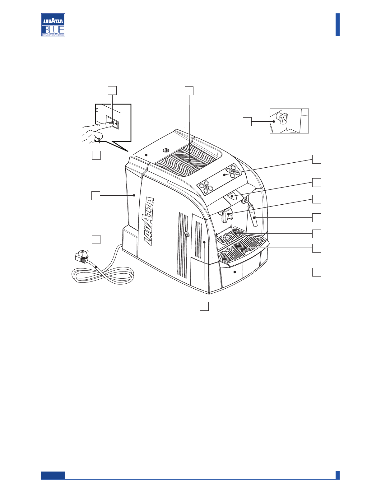
1.2.5. Machine composition
Note: if not expressly indicated in the text, the position numbers of the machine parts are referred to this figure.
1 Control panel
2 Capsule loading tray
3 Steam/hot water pipe (according to the model)
4 Coffee dispensing spout (the dispensing spout allows brewing 1 or 2 coffees according to the model)
5 Cup support (small cups)
6 Cup support (mugs)
7 Used capsule drawer and drip tray
8 Service area access door
9 Power cord
10 Cup warmer plate (according to the model)
11 On/off switch
12 Water tank
13 Water tank lid
1
9
8
10
2
Manual code 10083445 / Rel. 0.00 / April 2010
Maintenance manual for technical assistance LB 2300-2301-2302-2311-2312
4
11
12
13
2
4
3
5
6
7

1.2.6. Internal components
1 Steam solenoid valve
2 Pressure relief valve
3 Power board
4 On/off switch
5 Safety fuses
6 Connection for power cord
7 IRDA for programming
8 RS232 connector for programming
9 Connector for payment systems
10 Coupling for water tank
11 Capacitive sensor
3
Manual code 10083445 / Rel. 0.00 / April 2010
Maintenance manual for technical assistance LB 2300-2301-2302-2311-2312
12 Gear motor
13 Pump
14 Boiler
15 Capsule release coil
16 CPU board
17 Noise filtera
18 Safety thermostats
19 Water solenoid valve
20 Flowmeter
12
13
1
3
5
4
6
7
8
9
16
1
5
14
11
1
15
17
18
19
20
2
10
WITH STEAM
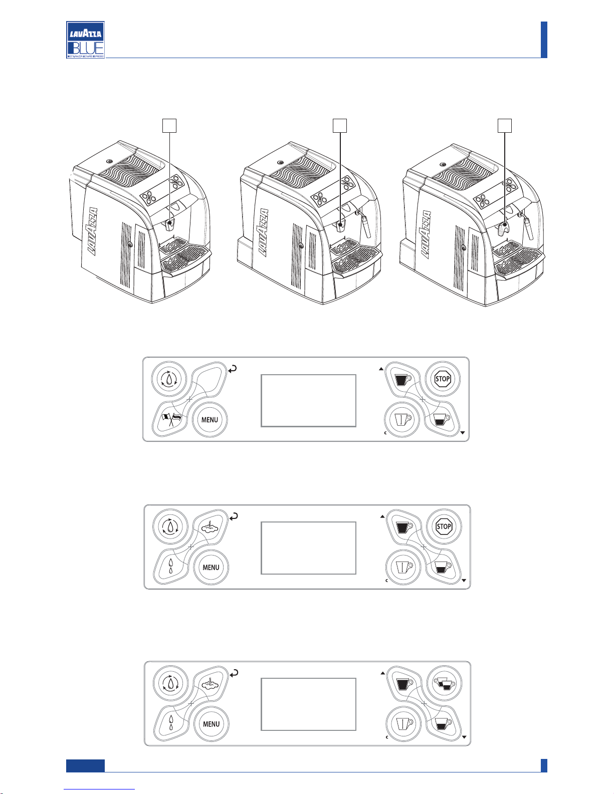
1.2.7. Range
4
Manual code 10083445 / Rel. 0.00 / April 2010
Maintenance manual for technical assistance LB 2300-2301-2302-2311-2312
Dispensing spout for 2 products (C)
Steam/hot water pipe
Dispensing spout for 1 product (B)
Steam/hot water pipe
Dispensing spout for 1 product (A)
DOUBLE CUP
WITH STEAM
SINGLE CUP
WITH STEAM
A
B
C
SINGLE CUP
Manual code 10083445 / Rel. 0.00 / April 2010
Maintenance manual for technical assistance LB 2300-2301-2302-2311-2312
5
1.2.8. Machine identification data
In the plate the following identification data of the
m
achine are indicated:
1.2.9. Technical specifications
Power supply voltage:
230 V~, 50 Hz
120 V~, 60 Hz
Power
Total: 1570 W
1100 W Coffee/hot water dispensing
470 W Additional for steam dispensing
Safety system:
Thermostat
Water level sensor:
Capacitive sensor
Pump:
Ulka brand with alternate piston and thermal
protector 100°C
48 W, 230V, 50 Hz, Type EP5 ca. 13-15 bar
Pressure relief valve:
Opens at 13-14 bar about
Water filter:
In the tank
Consumption:
During heating phase- about 6,8 A
Weight:
10,5 kg
Water tank capacity:
4 litres
Capsule container capacity:
Max. 20
-
Manufacturer;
- Machine name;
- Serial number;
- Power supply voltage (V) and frequency (Hz);
- Power consumption (W);
- Water mains pressure (MPa).
Note
In case of contact with authorized service centres,
please indicate the model and serial number.
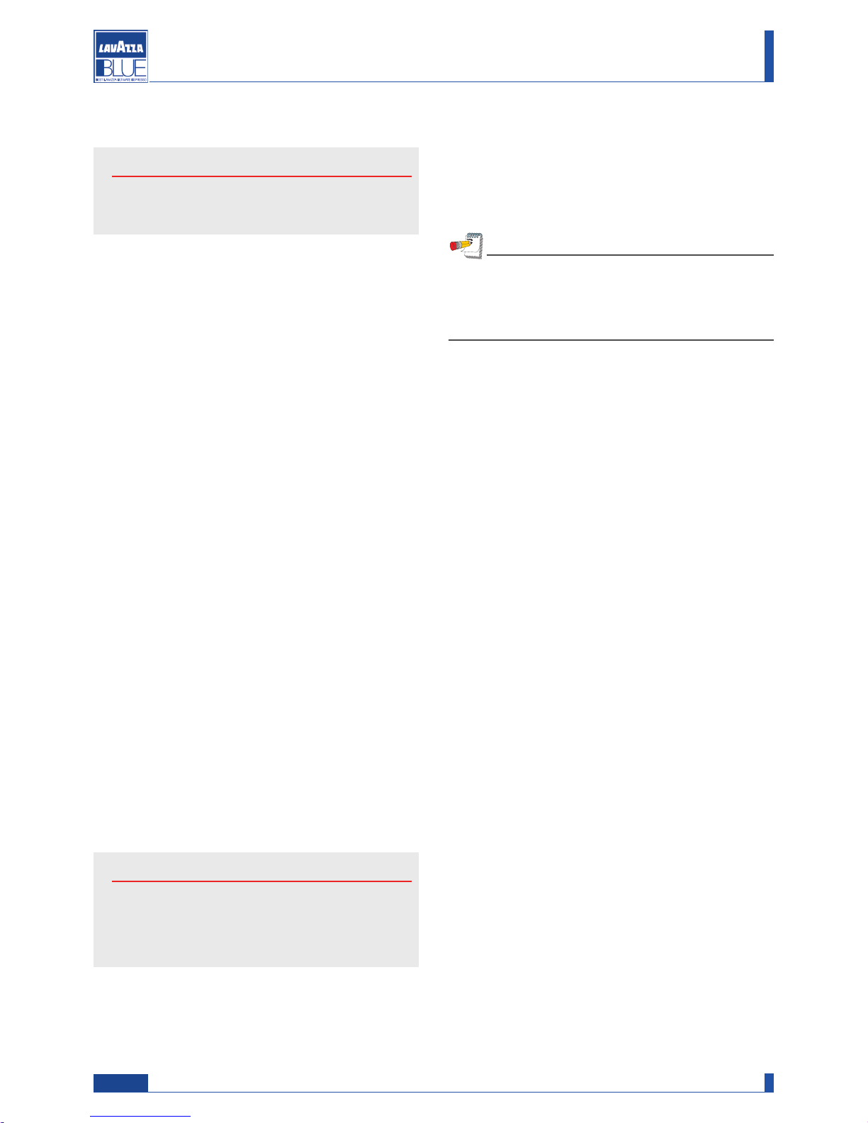
391
327
473
O
perating conditions:
Minimum temperature: 10°C
Maximum temperature: below 40°
M
aximum humidity: below 95%
Brewing temperature:
about 73°C - 83°C
1.2.10. Overall dimensions
Deep: 473 mm
Width: 327 mm
Height: 391 mm
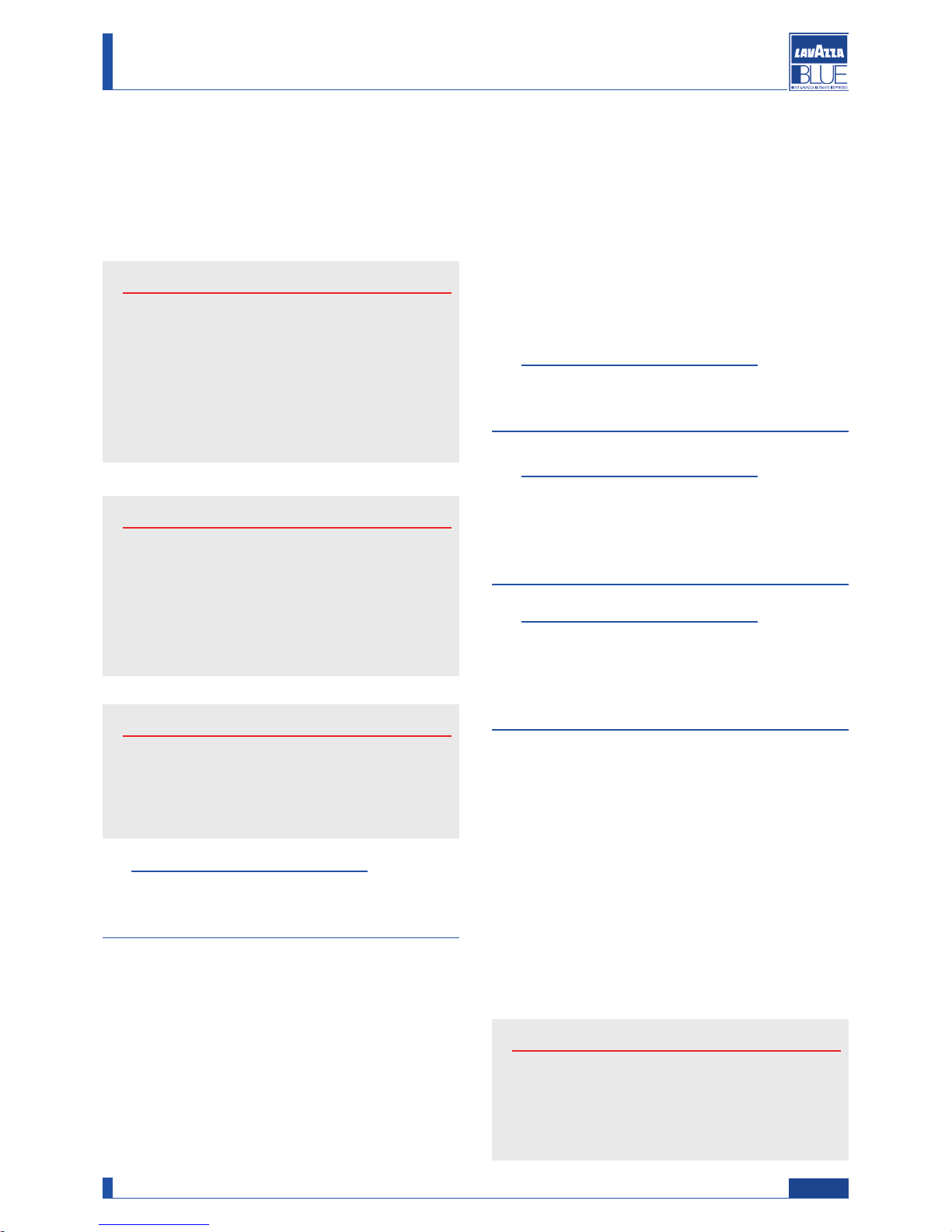
1.2.11. List of the accessories supplied with
the machine
Booklet: Instructions for using the
machine.
Water hardness test: Quick test to determine the hardness of the water used to prepare beverages; this is a very
important test to set the hardness of the water used by the
machine.
Key for water tank access: prevents
access to water tank by unauthorised personnel.
BRITA INTENZA filter
2. GENERAL SAFETY RULES
Attention
During the repair of the machine all the normal
safety protections, designed to avoid accidents
are disabled. Adopt all the measures necessary
to avoid accidents.
• Power connection should be made in compliance
with local standards in force.
• The electric socket connecting the machine should:
- conform to the type of plug installed on the machine;
- comply with the data provided on the plate placed on
the bottom of the apparatus;
- be connected to ground.
• The electric parts of the machine must not:
- enter into contact with any type of liquid: danger of
electric shock and/or fire;
- be manipulated by humid or wet hands;
- be tampered with.
• It is forbidden:
- To use the machine near flammable substances
and/or explosives and/or in an atmosphere with any
risk of fire;
- To use spare parts not advised by the manufacturer;
- Carry out any type of technical modification not covered in the normal procedures of diagnosis and repair.
• Before carrying out any operation on the machine
ensure that the plug is disconnected from the current
and that the machine has cooled.
• Maintenance operations on the machine should be
carried out by a single person; if a second person
must intervene, this person should be advised of the
potential hazards relevant to the operation underway.
• In case of fire use carbon dioxide (CO2) extinguishers. Do not use water or powder extinguishers.
Attention
Read the entire manual carefully and the follow
ing general safety rules..
2.1. Stop functions
To stop the machine turn the main switch to “0” (OFF).
2.2. Safety devices
Two Klixon thermostats with manual reset avoid any
overheating of the boiler.
2.3. Residual risks
In this chapter are illustrated the risks that the user may
incur in if he doesn’t comply with the specific safety
rules (as described in this booklet).
The appliance must be connected to ground
If it is not done, the appliance can become a source of
dangerous electrical discharges as it is no longer able
to discharge electricity to earth.
Do not use running water for washing
The use of pressurised water directly on the machine
can seriously damage electrical appliances. Never use
water jets to wash any part of the appliance.
Be careful with the hot water pipe
During use the hot water pipe may overheat, thus
becoming a source of danger. Handle this part carefully. Never direct steam or hot water jets directly on
parts of the body.
Do not work on the machine when it is powered
Before carry out any maintenance or repair on the
machine you must turn it off by means of the main network switch, or better yet, disconnecting the connection terminals in the network. Never remove any body
panels when the machine is supplied with electrical
power.
Note
The machines described in this publication, are
designed in compliance with the specific European
standards in force and therefore have measures of
protection in all the potentially hazardous parts.
Maintenance manual for technical assistance LB 2300-2301-2302-2311-2312
Manual code 10083445 / Rel. 0.00 / April 2010
6
Use of the appliance
This espresso coffee machine is an appliance for prof
essional use only. Any other type of use is considered
incorrect and therefore dangerous. Never allow children or incapacitated persons to use the machine..
Attention
Non-observance of the above rules can cause
serious harm to people, property or animals.
Never operate the electronic components when
the machine is still supplied with electrical power.
Shut off the machine completely by unplugging it
from the mains before carrying out any operation.
Warning
Do not use any containers that are not suitable for
foodstuffs.
Attention
Burn danger – During hot water and steam
dispensing, do not direct the jets toward others
or yourself. Grasp the pipe, exclusively on the
relevant protectors (12 and 17).
Attention
Any operation taken by the technician on the electronics of the machine when the machine is powered, automatically invalidates any guarantee.
The technician should know that the machine is
electrically connected and act accordingly.
3. INSTALLATION
3.1. Unpacking
O
pen the packaging, taking care not to damage it.
Remove the machine protections and the equipment
contained in the package.
Take the machine out.
Warning
It is prohibited to install the machine outside or in
places where water or steam jets are used.
Warning
The presence of magnetic fields or proximity with
electric machines which generate disturbances,
may cause malfunctions in the electronic control of
the machine.
Warning
With temperatures approaching 0°C there is the risk
of freezing internal parts of the machine which contain water. Do not use the machine under these conditions.
3.2. Mounting-Positioning
For the correct operation of the machine, the following
advice is given:
- environmental temperature: 10°C ÷ 40°C;
- maximum humidity: 90%;
- the area must be ready for the installation of the
machine;
- the place where the machine is installed should be
flat, solid and still; the surface must not have an incli-
nation of more than 2°;
- the area should be sufficiently illuminated, ventilated,
hygienic and equipped with a readily available power
outlet.
Attention
Sufficient space must be allowed to access the
machine and the plug, to allow the user to move
freely and to be able to immediately leave the
area in an emergency.
7
Maintenance manual for technical assistance LB 2300-2301-2302-2311-2312
Manual code 10083445 / Rel. 0.00 / April 2010

3.3. Machine positioning
Warning
Check that the surface prepared for the machine
installation, has dimensions and sturdiness suitable
to safely support the machine.
N
ote
For a correct ergonomic use of the machine, place
it on a working surface not lower than one meter
from the floor.
4. HANDLING AND STORAGE
4.1. Handling
During handling and transport, the machine must
remain in a vertical position according to the directions
on the packaging. Carry out lifting and positioning with
care. Do not shake the machine.
4.2. Storage
The machine should be stored according to the following conditions:
- minimum temperature: above 4°C;
- maximum temperature: below 40°C;
- maximum humidity: below 95%.
The machine is packaged in cardboard and polystyrene.
5. DISMANTLING
E
nvironment
Disposal of machine components after dismantling,
should be carried out with respect for the environment, avoiding pollution of the soil, water and air.
Any operation should comply with local legislation
in force.
8
Manual code 10083445 / Rel. 0.00 / April 2010
Maintenance manual for technical assistance LB 2300-2301-2302-2311-2312
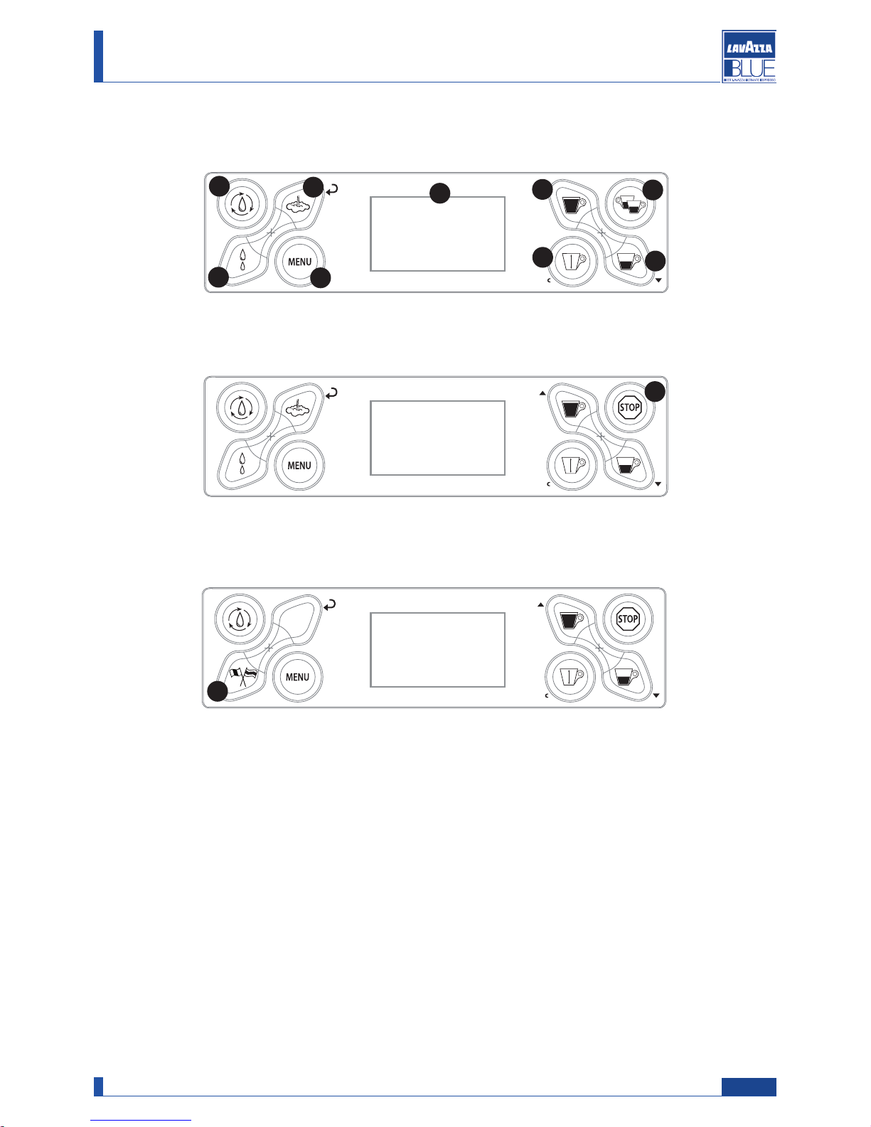
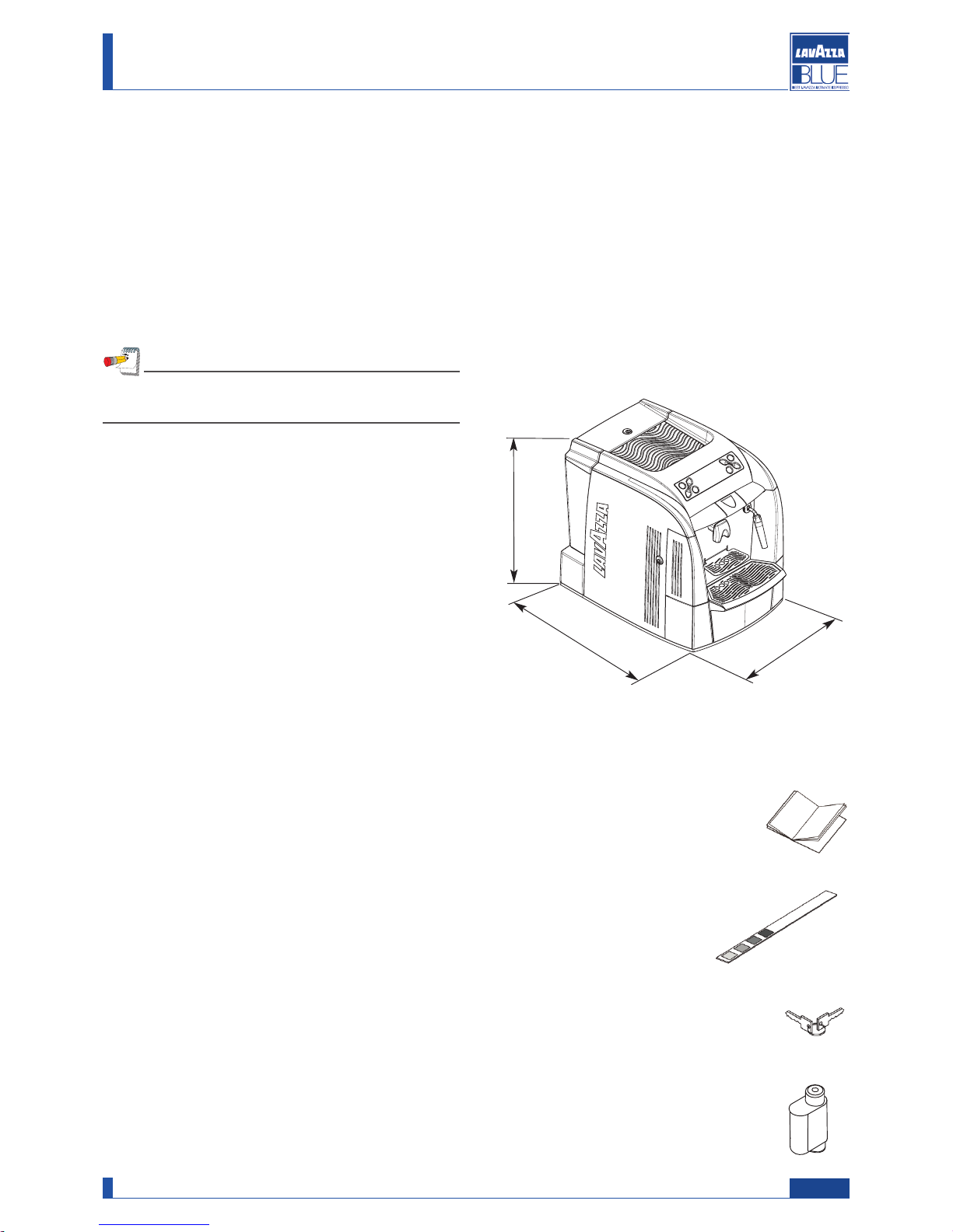
6. USER MENU
WITH STEAM
DOUBLE CUP
WITH STEAM
SINGLE CUP
WITH STEAM
SINGLE CUP
77
88
99
66
1100
1111
22
11
44
33
55
9
Manual code 10083445 / Rel. 0.00 / April 2010
Maintenance manual for technical assistance LB 2300-2301-2302-2311-2312

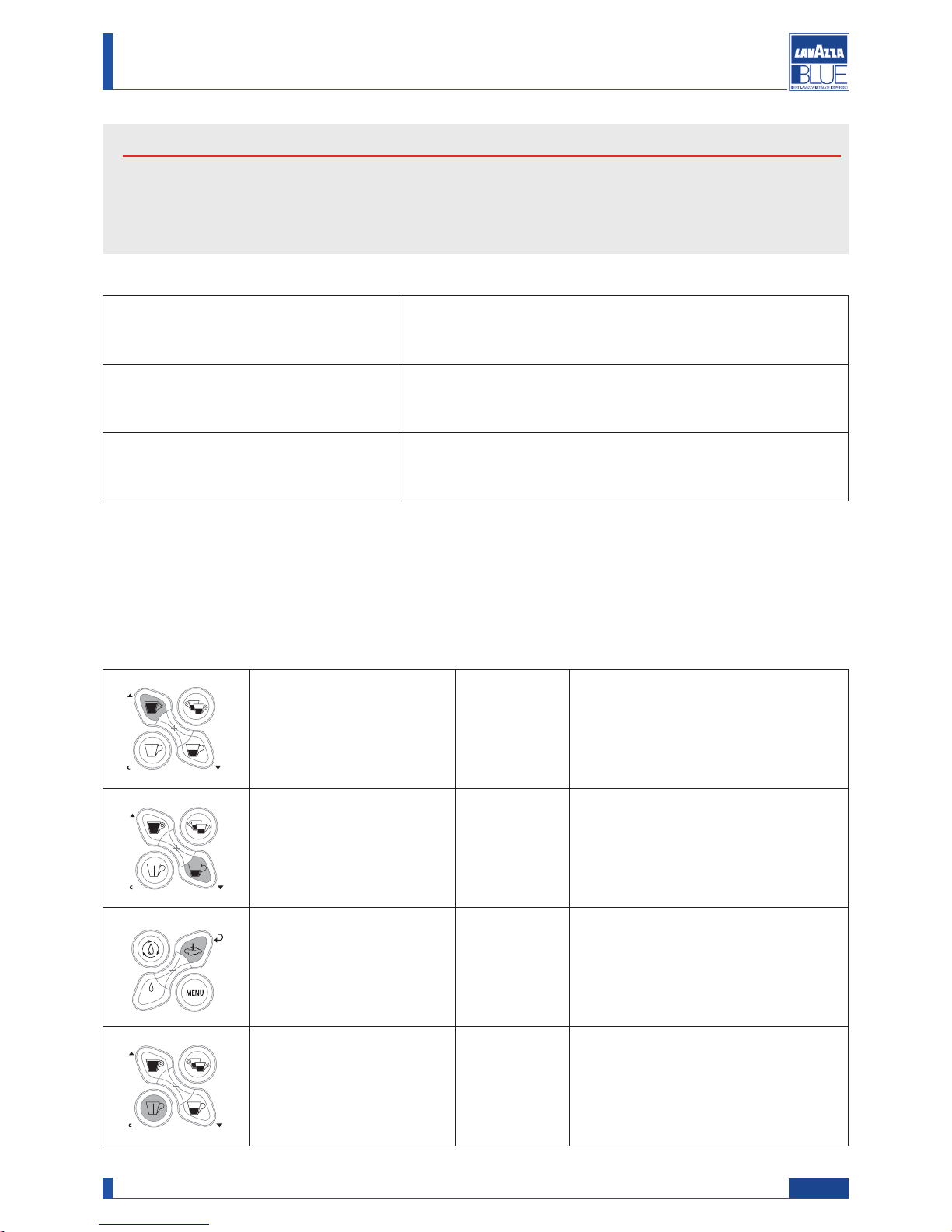
Press the MENU button (8) to access the QUICK MENU that allows the following operations:
- Change the language
- Activate/deactivate the cup warmer (according to the model)
- Wash the brew unit
- Set the rinse cycles
- Descale the machine
- Activate/deactivate the stand-by mode (to activate the energy saving mode)
BUTTON DESCRIPTION
0
1) Hot water dispensing
Press this button for 1 second and the machine immediately dispenses hot water.
0
2) Steam dispensing
Press this button for 1 second and the machine immediately dispenses steam.
03) Manual dispensing
button
Press this button to dispense a quantity of product that the user can manually
control (the user must stop the dispensing by pressing again the button).
04) Long coffee button
Press this button and the machine dispenses a long coffee (dose programmed by
the service provider).
05) Espresso button
Press this button and the machine dispenses an espresso coffee (dose programmed by the service provider).
06) Double espresso Press this button and the machine dispenses a double espresso.
07) Rinse Press this button for 1 second to carry out a rinse cycle of the internal circuits.
08) MENU Press this button for 1 second to display the user menu.
09) LCD display
Displays the machine status and alarm signals, and guides the user to operate the
machine.
10) Stop Press this button to stop coffee or steam/hot water dispensing.
11) Language Press this button for 1 second to display messages in the desired language.
10
Manual code 10083445 / Rel. 0.00 / April 2010
Maintenance manual for technical assistance LB 2300-2301-2302-2311-2312
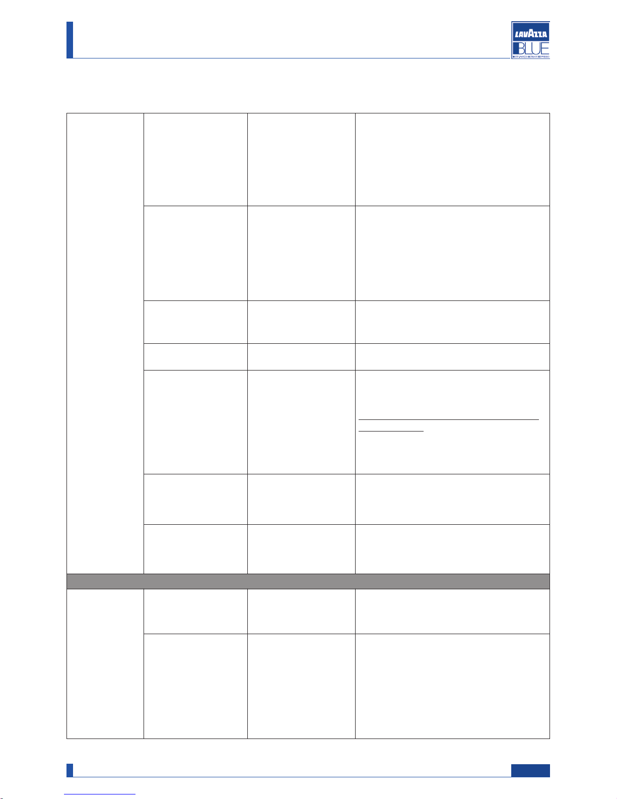
BUTTON DESCRIPTION
0
2) Enter/Confirm Press the button to select the function or confirm the command.
06) Page UP
Press the button to change function or parameter.
08) ESC Press the button to exit the function.
09) Page DOWN Press the button to change function or parameter.
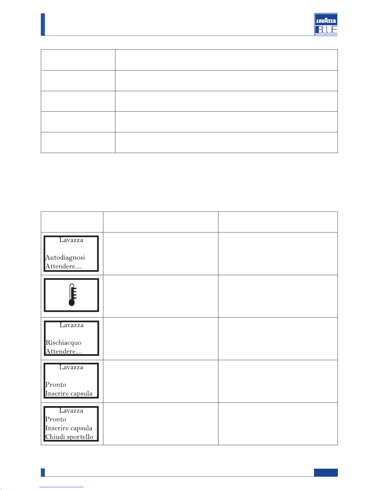
DISPLAY MEANING ACTIONS
The machine is checking the components. Wait for the check to conclude automatically.
The machine is warming up Wait for this step to conclude automatically.
The machine is performing the circuit
rinse cycle with fresh water.
Wait for the rinse cycle to end automatically.
The machine is ready to brew coffee. It is possible to dispense the coffee/product.
The capsule loading tray has been opened.
Place a capsule in the tray and close it.
Close the tray without the capsule.
6.1. Machine warnings
11
Manual code 10083445 / Rel. 0.00 / April 2010
Maintenance manual for technical assistance LB 2300-2301-2302-2311-2312
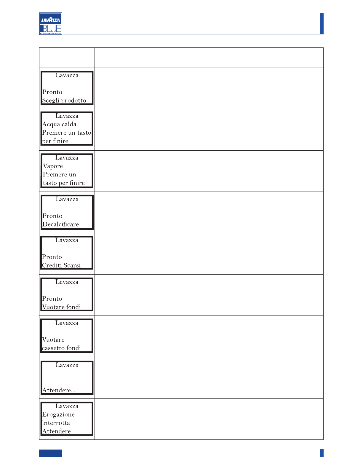
DISPLAY MEANING ACTIONS
The tray has been closed with a capsule
inside.
Dispense the product.
The machine is dispensing hot water.
Stop the dispensing by pressing the hot
water button.
The machine is dispensing steam.
Stop the dispensing by pressing the steam
button.
The machine signals that a descaling cycle
has to be carried out.
Start the descaling cycle.
The machine is alerting the user that credits for product brewing have almost run
out.
Request assistance from the service provider to acquire new credits.
Indicates that the used capsule drawer
should be emptied, though further products
can still be dispensed.
With the machine stopped and switched
on, remove the used capsule drawer and
empty it.
Indicates that the used capsule drawer
must be emptied because further products
may not be dispensed.
With the machine stopped and switched
on, remove the used capsule drawer and
empty it.
The used capsule drawer has been removed following a machine warning.
Empty the used capsule drawer and wait
for the following message "insert drawer"
to appear.
The machine has interrupted the brewing
cycle.
An alarm signal has been triggered, stopping the brewing cycle.
Contact the service provider, if necessary.
12
Manual code 10083445 / Rel. 0.00 / April 2010
Maintenance manual for technical assistance LB 2300-2301-2302-2311-2312
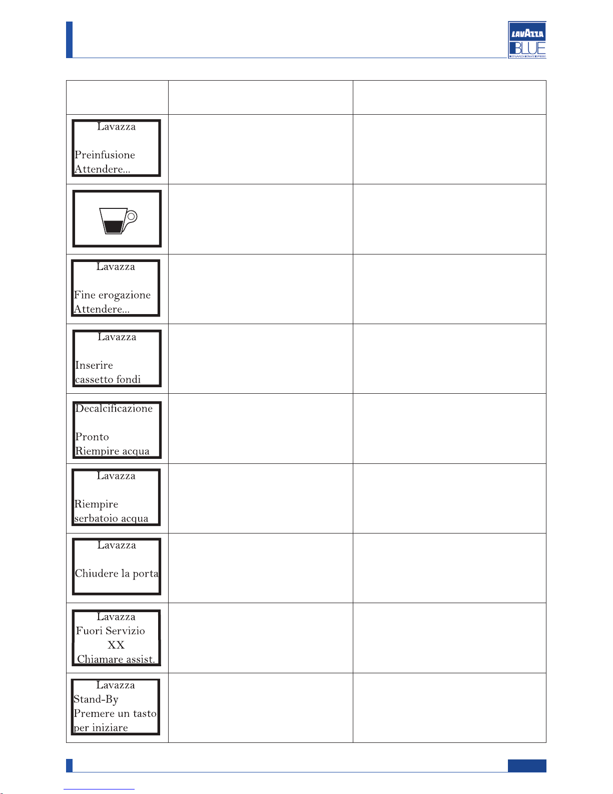
DISPLAY MEANING ACTIONS
The machine is performing the pre-infusion cycle and stops brewing the product.
Wait for the product brewing to restart automatically.
The machine has started the product brewing cycle.
Wait for the brewing automatically or
manually to end.
End brewing, the machine is being returned to the ideal conditions for the next
brewing cycle.
The used capsule drawer has been
removed from its seat.
Insert the used capsule drawer.
The machine alerts that the water tank
should be filled though further product
can still be dispensed.
Fill the water tank.
The water tank is empty. Fill the water tank.
The front service door is open.
Close the door. If the door is closed and
the warning persists, request assistance.
There is a machine malfunction. Refer to the notes on chap. 8.3.
The machine is in energy saving mode.
Press any button or open the capsule loading tray to activate the machine.
13
Manual code 10083445 / Rel. 0.00 / April 2010
Maintenance manual for technical assistance LB 2300-2301-2302-2311-2312

DISPLAY MEANING ACTIONS
The machine is filling the hydraulic circuit.
Wait for this operation to be successfully
completed.
The descaling filter must be replaced.
Request assistance from the service provider.
6.2. Machine programming (service provider)
To access the programming menu carry out the following:
Turn the machine off using the on/off switch.
Turn the machine on using the on/off switch and while
the hourglass shows up, keep pressed the steam button
until the menu appears.
Attention
These menus are PASSWORD protected.
14
Manual code 10083445 / Rel. 0.00 / April 2010
Maintenance manual for technical assistance LB 2300-2301-2302-2311-2312
Attention
The chosen PASSWORD (default 0000), should be changed during the first machine start up in such away
to prevent unauthorised access.
It is possible to change the password using either the service or the programming menu.
Programming menu Access to the programming menu (the password is requested)
Service menu Access to the service menu (the password is requested)
Exit Exits the programming menu
“Page up/change” button
This button
allows :
- Scrolling the pages within a menu
- Changing the parameters when they
are made editable using the “OK”
button
“Page down/change” button
This button
allows :
- Scrolling the pages within a menu
- Changing the parameters when they
are made editable using the “OK”
button
“OK” (ENTER) button
This button
allows :
- Selecting the displayed function
- Making changeable a parameter/value
- Confirm the parameter/value when it
is made editable
“ESC” button
This button
allows :
Exiting without changing the edited or
selected parameter.
6.3. Programming commands
The buttons of the control panel have different functions when the programming or service menu are entered.
15
Manual code 10083445 / Rel. 0.00 / April 2010
Maintenance manual for technical assistance LB 2300-2301-2302-2311-2312

1. Programming menu Press ENTER to access the programming menu
Password Enter password
Set value
Default: 0000
Enter the previously stored password (4 digits)
for accessing the password function
1.1.
Identification
1.1.1. Admin/affiliate PIN
Default 00000
Identifies the Service Provider or Administratorʼs
code: Numerical value between 0 and 65535
1.1.2. Model (Read only) Identifies the machine model.
1.1.3. Version
(Read only) Identifies the version of the machineʼs software.
1.1.4. Point of sale
Default 00000
Identifies the point of sale: Numerical value between 0 and 65535. Enter the selected number.
This number will then be
displayed.
1.2.
Setup
1.2.1.
Standard temperature
Default: 100°C
Boiler operating temperature (in degrees centigrade) when the machine is ready to be used.
Range: 90° - 105°.
1.2.2.Progr.dose
1.2.2.1.Short prod.dose
Default: 140
Quantity for espresso coffee (this is a numerical
parameter with no physical correspondent, e.g. cc).
1.2.2.2.Long prod. Dose
Default 173
Quantity for long coffee (this is a numerical parameter with no physical correspondent, e.g. cc).
1.2.2.3.Free prod.dose
Default 615
Maximum amount of manually dispensed product
(this is a numerical parameter with no physical correspondent, e.g. cc).
1.2.2.2.Double dose
prod.dose
Default 210
Quantity for double espresso coffee (this is a
numerical parameter with no physical correspondent, e.g. cc).
1.2.3.Pre-infusion
Default: Media
Pre-infusion time
No, Short, Medium, Long
1.2.4.Filter coffee
Default: No
“Yes” enables the filter coffee function. Filter
coffee can only be brewed by pressing “ESC”.
The filter operation is not available.
1.2.5.
Descaling
1.2.5.1. Water hardness
Default: 3
Values 0-4. “0” disables descaling checks. With
hardness 1, 2, 3 and 4, descaling checks are
activated and an alarm signal will appear after
240, 180, 120 or 60 litres of water that have
been treated. (Values from 5 to 9 will not be
accepted)
1.2.5.2. Descal.warning
Default: Yes
“Yes” enables display of the descaling alarm
signal.
1.2.6.
Filter warning
Default: No
“Yes” enables display of the filter replacement
alarm signal. When enabled, the alarm signal
appears after approximately 60 litres of water
have been treated, or in any event after 60 days.
6.4. Table of programming menu
16
Manual code 10083445 / Rel. 0.00 / April 2010
Maintenance manual for technical assistance LB 2300-2301-2302-2311-2312
1.2.
Setup
1.2.7.Credits 1.2.7.1.Credit check
(Read only)
Yes: the machine checks the remaining credits.
N
o: The machine does not check remaining credit.
1.2.7.2.Credit warning
Default: Yes
“Yes” enables
- display of the credit alarm signal when the
preset minimum number of credits is reached;
- display of the "no credit" alarm signal
when the credits have been run out
1.2.7.3.Load credits
Default: 000
Number of credits added.
Value: 0-255
1.2.8.Language
Default: Italian
Select language
1.2.9.Grounds delay
Default: 5
Time, in seconds, after which the machine
resets used capsule counter (with the used
capsule drawer removed)
this delay applies only if the relevant alarm
signal is shown.
After this time the warning or the alarm
signal is cancelled.
Values: 0 - 255 seconds
1.2.10. Contrast
Default: 35
To set the display contrast
Values: 20 - 50
1.2.11 Brightness
Default: 150
To set the display brightness
Values: 30 - 255
1.3. Stand-by
1.3.1. Activate?
Default: No
“Yes” enables energy saving mode.
1.3.2.
Stand-by delay
Default: 60
- When the machine is in standby mode, it
switches off automatically after the defined
time has elapsed following the last use.
- When the machine is in standby mode, the
boiler temperature is reduced after the defined time has elapsed
Values: 5 - 240 Minutes
17
Manual code 10083445 / Rel. 0.00 / April 2010
Maintenance manual for technical assistance LB 2300-2301-2302-2311-2312
 Loading...