

LAVAZZA LB 2800, LB 2810, Blue LB 2800, Blue LB 2810 Maintenance Manual
LB 2800 - LB 2810
MAINTENANCE MANUAL FOR
TECHNICAL ASSIST ANCE
MAN UAL COD E 10066574 / REL. 0.0 0 / MA RCH 2009
LB 2800
Machine code
10080022
LB 2810
Machine code
10080005
Manual code
10066574
Rel. 0.00
Edition 03/2009
© Copyright LAVAZZA S.p.A.
Tel. 0 03 9 .01 1 .2 3 984 2 9
Fa x 00 39 .0 11 .2 39 80 46 6
te chn ic a lserv ice @la vazza.it

Table of contents
1. GENERAL INFORMATION . . . . . . . . . . . . . . . . . . . . . . . . . . . . . . . 1
1.1. Designated personnel . . . . . . . . . . . . . . . . . . . . . . . . . . . 1
1.2. Structure of the manual . . . . . . . . . . . . . . . . . . . . . . . . . . 1
1.2.1. Scope and content . . . . . . . . . . . . . . . . . . . . . . . . . . . . . . 1
1.2.2. Users . . . . . . . . . . . . . . . . . . . . . . . . . . . . . . . . . . . . . . . . 1
1.2.3. Preservation . . . . . . . . . . . . . . . . . . . . . . . . . . . . . . . . . . . 1
1.2.4. Messages used . . . . . . . . . . . . . . . . . . . . . . . . . . . . . . . . . 1
1.2.5. Machine composition . . . . . . . . . . . . . . . . . . . . . . . . . . . . 2
1.2.6. Internal components . . . . . . . . . . . . . . . . . . . . . . . . . . . . . 3
1.2.7. Main components . . . . . . . . . . . . . . . . . . . . . . . . . . . . . . . 4
1.2.7.1. Boiler . . . . . . . . . . . . . . . . . . . . . . . . . . . . . . . . . . . . . . . . 4
1.2.7.2. Delivery group . . . . . . . . . . . . . . . . . . . . . . . . . . . . . . . . . . 4
1.2.7.3. Automatic Water Entry (A.E.A) . . . . . . . . . . . . . . . . . . . . . 5
1.2.7.4. Volumetric dosing device . . . . . . . . . . . . . . . . . . . . . . . . . 5
1.2.7.5. Checking boiler temperature/pressure . . . . . . . . . . . . . . . 5
1.2.7.6. Pumping system . . . . . . . . . . . . . . . . . . . . . . . . . . . . . . . . 6
1.2.7.7. Valve group . . . . . . . . . . . . . . . . . . . . . . . . . . . . . . . . . . . . 6
1.2.7.8. Electronic control unit . . . . . . . . . . . . . . . . . . . . . . . . . . . 6
1.2.7.9. Softener . . . . . . . . . . . . . . . . . . . . . . . . . . . . . . . . . . . . . . 6
1.2.8. Machine identification data . . . . . . . . . . . . . . . . . . . . . . . 7
1.2.9. Technical specifications . . . . . . . . . . . . . . . . . . . . . . . . . . 7
1.2.10. Overall dimensions . . . . . . . . . . . . . . . . . . . . . . . . . . . . . . 7
2. GENERAL SAFETY RULES . . . . . . . . . . . . . . . . . . . . . . . . . . . . . . 7
2.1. Stop functions . . . . . . . . . . . . . . . . . . . . . . . . . . . . . . . . . 8
2.2. Safety devices . . . . . . . . . . . . . . . . . . . . . . . . . . . . . . . . . 8
2.3. Residual risks . . . . . . . . . . . . . . . . . . . . . . . . . . . . . . . . . . 8
I
Manual code 10066574 / Rel. 0.00 / March 2009
Maintenance manual for technical assistance - LB 2800 - LB 2810
I

Maintenance manual for technical assistance - LB 2800 - LB 2810
Manual code 10066574 / Rel. 0.00 / March 2009
II
3
. INSTALLATION . . . . . . . . . . . . . . . . . . . . . . . . . . . . . . . . . . . . . . . . 9
3
.1. Unpacking . . . . . . . . . . . . . . . . . . . . . . . . . . . . . . . . . . . . . 9
3
.2. Mounting-Positioning . . . . . . . . . . . . . . . . . . . . . . . . . . . . . 9
3
.3. Machine positioning . . . . . . . . . . . . . . . . . . . . . . . . . . . . . 10
3.4. Water connection . . . . . . . . . . . . . . . . . . . . . . . . . . . . . . . 11
3.5. Electric connection . . . . . . . . . . . . . . . . . . . . . . . . . . . . . . 12
3.6. Machine start up . . . . . . . . . . . . . . . . . . . . . . . . . . . . . . . . 12
4. HANDLING AND STORAGE . . . . . . . . . . . . . . . . . . . . . . . . . . . . . 13
4.1. Handling . . . . . . . . . . . . . . . . . . . . . . . . . . . . . . . . . . . . . . 13
4.2. Storage . . . . . . . . . . . . . . . . . . . . . . . . . . . . . . . . . . . . . . . 13
5. ACCESSORIES INCLUDED . . . . . . . . . . . . . . . . . . . . . . . . . . . . . 13
6. DISMANTLING . . . . . . . . . . . . . . . . . . . . . . . . . . . . . . . . . . . . . . . 13
6.1. Instructions for end of life treatment . . . . . . . . . . . . . . . . 14
7. PROGRAMMING . . . . . . . . . . . . . . . . . . . . . . . . . . . . . . . . . . . . . . 14
7.1. Programming coffee doses . . . . . . . . . . . . . . . . . . . . . . . . 14
7.2. Programming cappuccino doses . . . . . . . . . . . . . . . . . . . 15
7.3. Programming hot water doses . . . . . . . . . . . . . . . . . . . . . 15
7.4. Programming the coffee-cappuccino sequence . . . . . . . 16
7.5. Loading default data . . . . . . . . . . . . . . . . . . . . . . . . . . . . . 16
7.6. Programming boiler temperature . . . . . . . . . . . . . . . . . . . 17
7.7. Coffee dispensing . . . . . . . . . . . . . . . . . . . . . . . . . . . . . . . 17
7.8. Preparation of hot beverages . . . . . . . . . . . . . . . . . . . . . . 18
7.9.
Cappuccinatore . . . . . . . . . . . . . . . . . . . . . . . . . . . . . . . . . 18
8. PROBLEMS, CAUSES AND SOLUTIONS . . . . . . . . . . . . . . . . . . 20
9. CHECKS AND MAINTENANCE . . . . . . . . . . . . . . . . . . . . . . . . . . 26
9.1. Replacement of the perforator . . . . . . . . . . . . . . . . . . . . . 27
10. CLEANING . . . . . . . . . . . . . . . . . . . . . . . . . . . . . . . . . . . . . . . . . . . 28
11. WIRING DIAGRAM . . . . . . . . . . . . . . . . . . . . . . . . . . . . . . . . . . . . 30
12. HYDRAULIC DIAGRAM . . . . . . . . . . . . . . . . . . . . . . . . . . . . . . . . 31
Maintenance manual for technical assistance - LB 2800 - LB 2810
Manual code 10066574 / Rel. 0.00 / March 2009
1
1. GENERAL INFORMATION
1
.1. Designated personnel
The machine may be operated only by a qualified
technician who has read this manual and, moreover
who:
- is able to carry out repairs in case of serious malfunc
tion and who has read this manual and all the infor-
mation relative to safety;
- is able to understand the entire contents of the
manual and to correctly interpret the drawings and
diagrams;
- has knowledge of the appropriate hygiene, workplace safety, technology and security measures;
- knows how to act in an emergency, where to find the
personal protective equipment and knows how to
use it.
Attention
Before any operation is carried out on the machine, the qualified technician must carefully read
the instructions contained in this publication.
If there is any doubt about the correct interpretation of
the instructions, contact the manufacturer to obtain the
necessary clarification.
1.2.2. Users
This manual is designed for technicians qualified for
the maintenance of the machine.
Attention
The ATTENTION messages indicate a danger,
possibly lethal, for the technician. The operations
described after this message must be carried out
carefully and safely using the personal protective
equipment.
Warning
The WARNING messages are displayed before procedures that, if not observed, could cause damage
to the machine.
Warning
If this manual is damaged or lost, a new copy
should be immediately requested from the manufacturer or authorised distributor of the country
where the machine is used.
1.2.4. Messages used
Environment
The ENVIRONMENT messages are displayed before procedures that, if not observed, could cause
damage to the environment.
Attention
The use of the machine by personnel without the
prerequisites needed is prohibited.
1.2. Structure of the manual
The technician must carefully read the information in
this manual.
1.2.1. Scope and content
This manual can provide the technician with all the
information necessary for the maintenance
of the machine.
Attention
The undertaking of any operation on the machine,
without having read and understood the contents
of this manual is prohibited.
The manufacturer is not responsible for damage derived from the failure to follow this rule.
1
.2.3. Preservation
In order to be able to guarantee the integrity and utility
of this manual the following guidelines should be
observed:
- employ this manual in such a way that it remains
undamaged and whole;
- do not for any reason, remove, tear, or write over any
part of the manual;
- keep the manual in an area protected from humidity
and heat, in such a way that the quality and legibility
of the publication are not compromised.
Note
The NOTE messages show further information useful for the maintenance technician.
5
2
2
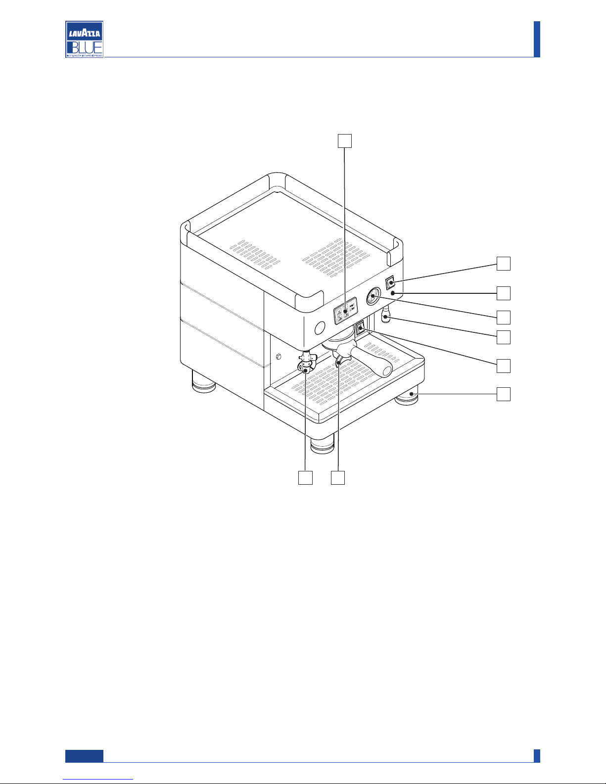
1 Push button panel
2 Hot water dispensing push button
3 Boiler heating element indicator light working
4 Boiler pressure gauge
5 Hot water dispensing nozzle
6 Machine main switch
7 Adjustable foot
8 Coffee dispensing spout
9 Cappuccinatore
2
3
7
6
4
9
1
8
5
2
Manual code 10066574 / Rel. 0.00 / March 2009
Maintenance manual for technical assistance - LB 2800 - LB 2810
1.2.5. Machine composition
Note: if not expressly indicated in the text, the position numbers of the machine parts are referred to this figure.
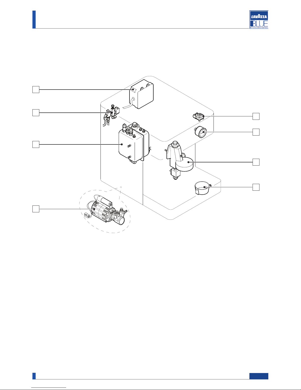
1.2.6. Internal components
1 Boiler
2 Electronic control unit
3 Volumetric dosing device
4 Boiler pressure gauge
5 Dispensing assembly
6 Drain tub
7 Internal motor pump
8 Cold water mixing tap
4
6
7
1
5
8
3
2
3
Manual code 10066574 / Rel. 0.00 / March 2009
Maintenance manual for technical assistance - LB 2800 - LB 2810
1.2.7. Main components
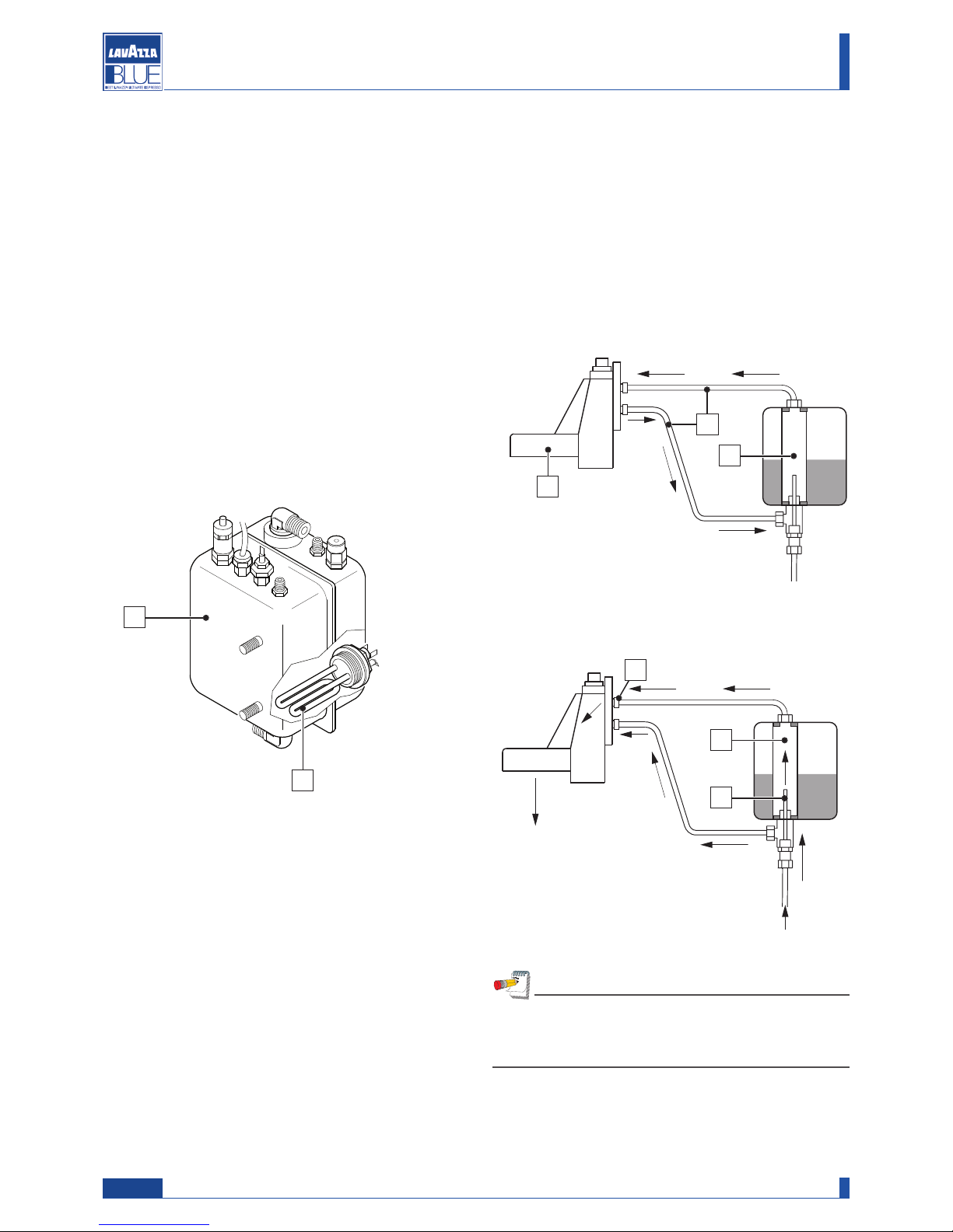
1.2.7.1. Boiler
The boiler is made of steel (A), to which is assembled
the heat exchanger which in turn is connected to the
dispensing group. Water for coffee delivery is taken
d
irectly from the heat exchanger.
D
uring delivery, cold water is sent to the inside of the
exchanger by means of the pump. Inside the heat
exchanger, cold water and the pre-existing hot water
are mixed, thus obtaining optimal water temperature
for coffee infusion.
The water is heated in the boiler by means of an electrical heating element immerged in the water (B).
A
- from the exchanger (3) the water is carried to the
g
roup duct (1) for delivery;
-
the pump allows the increase of the pressure of the
water flow up to 8-9 bar for delivery.
To increase of decrease the temperature of the coffee
i
n the cup, you must adjust the temperature of the
water in the boiler (see related paragraph).
At rest
In delivery
3
5
WWaatteerr
iinnlleett
CCooffffeeee
ddeelliivvee rryy
1
2
4
Manual code 10066574 / Rel. 0.00 / March 2009
Maintenance manual for technical assistance - LB 2800 - LB 2810
B
3
4
1.2.7.2. Delivery group
The delivery group and the heat exchanger are the fundamental components in obtaining espresso coffee.
Specifically, the purpose of the group is to dispense
the coffee.
This system includes heating of the dispensing assembly (1) through thermosiphon circulation (2) connected
to the heat exchanger (3). The same water is used for
dispensing coffee:
- activation of the solenoid valve and the pump allow
cold water to enter the exchanger (3) through the
injector (4);
Note
After lowering the temperature of the water in the
boiler, if the coffee is still too hot, you will need to
insert the choke provided on the upper pipe (5).
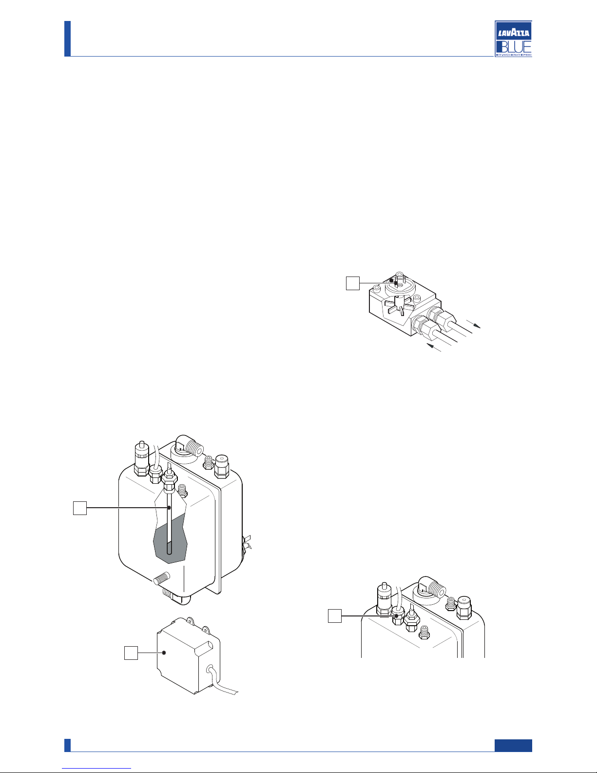
1.2.7.3. Automatic Water Entry (A.E.A)
The Automatic Water Entry system is for checking the
b
oiler level.
It is composed of:
- probe inserted in the boiler (A), composed of a stain-
less steel rod;
- electronic control unit (B);
- a pump which, along with the AEA solenoid valve,
allows water to flow into the boiler.
- AEA solenoid valve.
The electronic control unit controls the level of water in
the boiler. When the level drops, the contact with the
probe is broken. The control unit sends an impulse to
the inlet solenoid valve and to the motor pump, which
are activated to restore the normal level of water in the
boiler.
To avoid possible flooding due to machine malfunctions or leaks in the hydraulic circuit, the electronic
control unit includes a timing device that cuts off automatic filling after a maximum operating time of 120
seconds.
B
1.2.7.4. Volumetric dosing device
The volumetric dosing device installed on the EVD
e
lectronic machines serves the purpose of measuring
the quantity of water sent to the espresso delivery
group.
The dosing device generates an electrical impulse
which is sent to the electronic control unit. This impulse is read by the control unit and memorized during the
programming of the dose.
The flashing of the LED (1) indicates that the electrical
impulse has been sent from the dosing device to the
control unit.
1
1.2.7.5. Checking boiler temperature/pressure
The temperature (and as a result the pressure) in the
boiler is controlled by a special NTC sensor located on
the boiler (X).
This sensor constantly sends information to the electronic control unit, which in turn activates or deactivates the heating element by means of a power triac.
The default temperature is set in the factory at 120°C.
If you want to change this value, you can do so by
means of the procedure described in the chapter
“Programming of boiler temperature”.
Manual code 10066574 / Rel. 0.00 / March 2009
Maintenance manual for technical assistance - LB 2800 - LB 2810
5
A
X
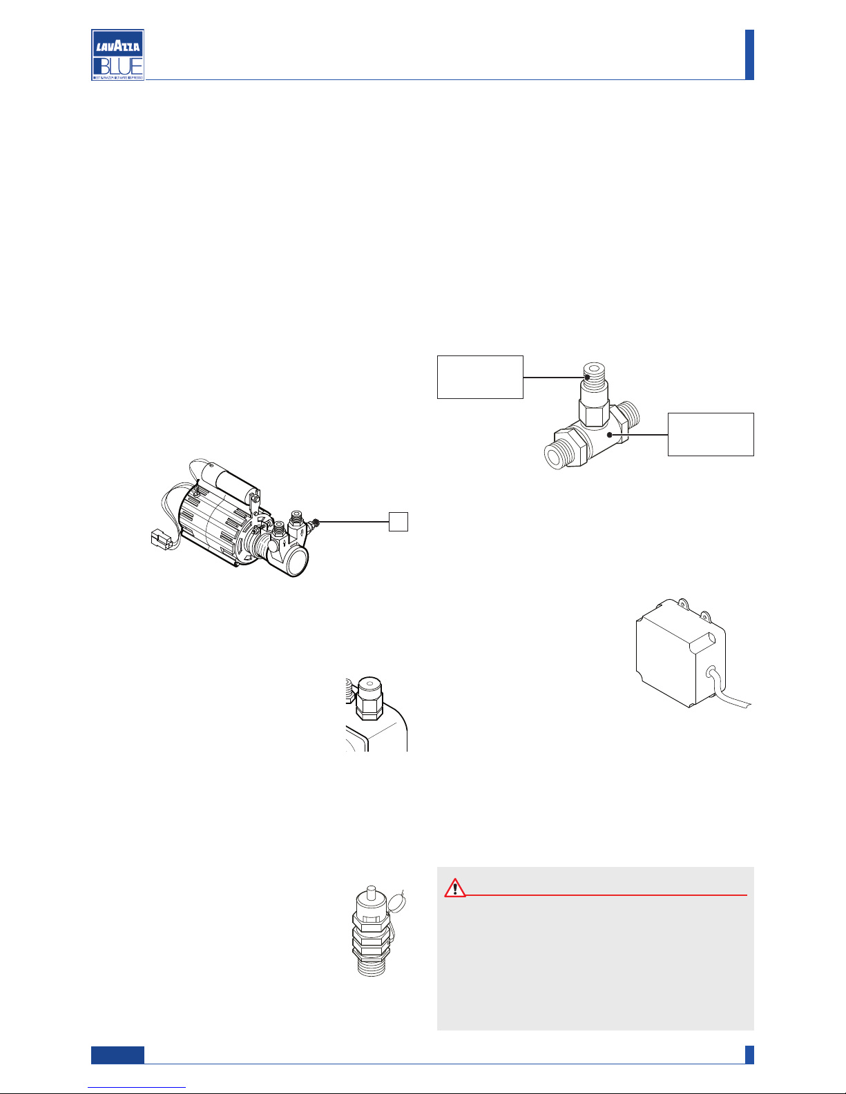
1.2.7.6. Pumping system
This is a component that feeds the machine, raising the
w
ater pressure to 8-9 bar for delivery of the coffee and
automatic filling of the boiler.
To adjust operating pressure proceed as follows:
- press a coffee delivery key;
-
connect a pressure gauge with an end of scale of
more than 9 bar to the connection on the plumbing
circuit (see plumbing diagram);
- Adjust the pressure by turning the screw located on
the pump (1) so as to obtain a pressure of between 8
and 9 bar. Tightening the screw increases the pressu-
re, and loosening it reduces the pressure;
- check the pressure using the pressure gauge.
1.2.7.7. Valve group
The valves are devices whose purpose is
to ensure the safety and proper operation
of the machine.
Negative pressure valve
The negative pressure valve eliminates the air in the
boiler during the machine’s warm-up phases.
Safety or pressure relief valve
The pressure relief valve guarantees that
the pressure in the boiler does not go
above 2 bar. If there is a malfunction, the
capacity of the valve is such that it can eliminate all the excess pressure from the
boiler.
Expansion - non-return valve
This is a valve consisting of an expansion valve and a
n
on-return valve.
- Expansion valve: the cold water sent from the pump
to the heat exchanger is heated.
T
his heating causes an increase in the volume of
water. To limit pressure increases in the hydraulic circuit, the valve limits the maximum internal pressure of
the circuit to 12 bar.
- Non-return valve: its function is that of preventing the
backflow of water from the exchanger in the hydraulic circuit.
Expansion
valve
Non-return
valve
6
Manual code 10066574 / Rel. 0.00 / March 2009
Maintenance manual for technical assistance - LB 2800 - LB 2810
1
Attention
The build-up of lime scale in the hydraulic circuit
and boiler inhibit thermal exchange, thus compromising proper operation of the machine.
Heavy incrustation in the boiler may cause long
machine shutdowns and in any case invalidate
any guarantee.
1.2.7.8. Electronic control unit
Its purpose is to electronically control the coffee dose
by means of the water flowing through the dosing device and to check the filling of the water in the boiler.
Furthermore, it also controls operation of the automatic cappuccinatore.
This control unit is set up to be
connected to the delivery
accounting systems by means
of a specific interface device.
1.2.7.9. Softener
Mains water contains insoluble salts, which cause the
build-up of lime scale deposits in the boiler and in
other parts of the machine. The softener makes it possible to eliminate or substantially reduce the presence
of these mineral salts.
Maintenance manual for technical assistance - LB 2800 - LB 2810
Manual code 10066574 / Rel. 0.00 / March 2009
7
1.2.8. Machine identification data
In the plate the following identification data of the
m
achine are indicated:
1.2.9. Technical data
Power supply voltage (V): 120 - 230 - 240
Boiler capacity (lt): 2
Frequency (Hz): 50 / 60
Power (W): model 120V (1270 W)
model 230V (1570 W)
model 240V (1710 W)
Boiler pressure (bar): 1,4 Max
Safety valve calibration (bar): 2
Supply water pressure (bar): 0 - 5 Max
Coffee dispensing pressure (bar): 8 - 9
Net weight (Kg): 31
Operating range: +5 +50 °C
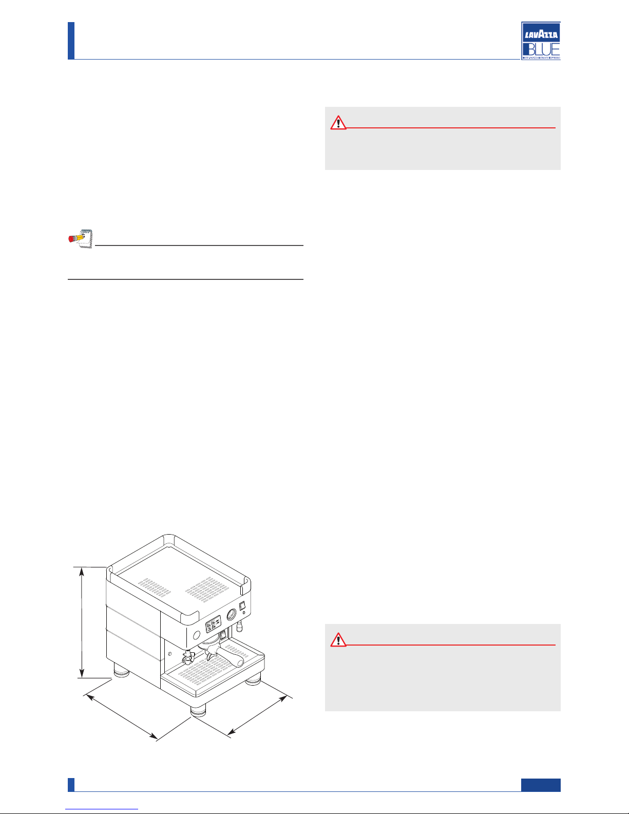
1.2.10. Overall dimensions
-
Manufacturer;
- machine name;
- serial number;
- power supply voltage (V) and frequency (Hz);
- power consumption (W);
- water mains pressure (MPa).
5
2
2
2. GENERAL SAFETY RULES
Attention
During the repair of the machine all the normal
safety protections, designed to avoid accidents
are disabled. Adopt all the measures necessary
to avoid accidents.
Note
In case of contact with authorized service centres,
please indicate the model and serial number.
• Power connection should be made in compliance
with local standards in force.
• The electric socket connecting the machine should:
- conform to the type of plug installed on the machine;
- comply with the data provided on the plate placed on
the bottom of the apparatus;
- be connected to ground.
• The electric parts of the machine must not:
enter into contact with any type of liquid: danger of
electric shock and/or fire;
- be manipulated by humid or wet hands;
- be tampered with.
• It is forbidden:
- To use the machine near flammable substances
and/or explosives and/or in an atmosphere with any
risk of fire;
- To use spare parts not advised by the manufacturer;
- Carry out any type of technical modification not
covered in the normal procedures of diagnosis and
repair.
• Before carrying out any operation on the machine
ensure that the plug is disconnected from the current
and that the machine has cooled.
• Maintenance operations on the machine should be
carried out by a single person; if a second person
must intervene, this person should be advised of the
potential hazards relevant to the operation underway.
• In case of fire use carbon dioxide (CO2) extinguishers. Do not use water or powder extinguishers.
Attention
Read the entire manual carefully and the follow
ing general safety rules.
470
322
435
 Loading...