

Page 1
Page 2
Table of contents
1 General information
2 Electrical diagram
3 Hydraulic diagram
4 Maintenance schedules
Maintenance manual for technical assistance
LB 1000 BLUE FAMILY
Machine code:
80601
Handbook code: 83346
Revision: September 2004
Rel: 1.00
Use only original spare parts
The manufacturer declines all responsibility
if non original spare parts are used
TECHNICAL ASSISTANCE
Tel. 0039 011 2398429
Fax 0039 011 23980466
E-mail: assistenzada@lavazza.it
“
“
“LB 1000 BLUE FAMILY”
© Copyright LUIGI LAVAZZA S.p.A
OD. 83346 / REL. 1.00 / SEPTEMBER 2004
C
Page 3
General information
• Preface
• Safety information
• Safety specifications
• Residual risks
• Environmental conditions allowed
• Warehousing
• Scrapping
1
1/6
• Transport
• List of tools necessary for maintenance
“LB 1000 Blue Family” Rel. 00 settembre 2004
“
“LB 1000 BLUE FAMILY”
2
OD. 83346 / REL. 1.00 / SEPTEMBER 2004
C
Page 4

Preface
1
General information
This manual contains information, safety instructions, spare parts and wiring
diagrams to carry out the correct maintenance and to solve eventual problems.
All rights reserved by Lavazza S.p.A. including the rights to reproduce the text
and images of this document or part of it.
The continuous development and improvement of the machine may have
caused modifications that are not included in this manual. Read it carefully and
keep it at hand for reference.
Before leaving the factory this specific machine's model has been submitted to
a strict control in order to guarantee reliability; therefore you should verify that
during transportation the dispenser has not incurred structural damages that
could compromise its operation and safety.
2/6
Some items illustrated in the figures of this manual could be different of those
on the machine; some components may be omitted to obtain illustrations.
Keep this manual in an accessible place near maintenance staff.
“LB 1000 Blue Family”
“
“LB 1000 BLUE FAMILY”
Rel. 00 settembre 2004
2
OD. 83346 / REL. 1.00 / SEPTEMBER 2004
C
Page 5
Safety information
Failure to comply with basic safety rules and precautions could cause
accidents during machine operation, maintenance and repair. An accident can
often be avoided by recognising potential hazardous situations before they
occur. The operator has to pay attention to potential hazards and have training,
competences and correct tools to carry out these tasks properly.
The improper use of the machine either during operation or maintenance could
be dangerous and cause serious accidents.
Do not operate the machine or carry out maintenance until these instructions
have been read and understood.
Safety precautions and warnings are given in this manual and indicated on the
machine. If the operator does not pay attention to these warnings he could
have an accident with serious consequences for himself and others.
General information
1
3/6
Lavazza S.p.A. does not foresee every possible situation that could be
potentially dangerous.
The warnings in this manual and on the machine are not exhaustive.
If tools, procedures, working methods or techniques not expressly
recommended by Lavazza S.p.A. are used, make sure that there is no risk of
personal injury or injury for other people.
Information, specifications and illustrations of this manual are based on the
information available at the moment of editing. Specifications, adjustments,
illustrations and other items can change anytime and these modifications can
influence the maintenance operation to be performed.
Use only original spare parts
The manufacturer declines any responsibility for the use of uncertified spare
parts.
“
“LB 1000 BLUE FAMILY”
OD. 83346 / REL. 1.00 / SEPTEMBER 2004
C
Page 6

Safety specifications
The following indications cannot completely protect from all dangers which
could be incurred while operating the “LB 1000” machine, good sense should
be used at all times and only experienced personnel should carry out
maintenance, along with measures to prevent accident.
In each section ulterior safety specific prescriptions for different operations are
described.
Do not operate the machine or perform ordinary maintenance before having
read and understood the instructions in the present manual.
Do not plug the machine into an outlet with a voltage different from that
indicated on the label on the bottom of the machine.
Some components of the machine operate at the net tension.
Do not touch electric wires, switches, push buttons etc... with wet hands.
Before proceeding with processing or intervention not scheduled, performed
following a different procedure from that one indicated in the manual, consult
Lavazza technical assistance.
General information
1
4/6
Do not position “LB 1000” machine in corrosive or explosive environment or
exposed to the atmospheric agents.
Keep the “LB 1000” machine free from extraneous material such as deposits,
tools and other objects that could damage the operation and cause harm to
people.
Avoid the use of inflammable or toxic solvents, benzene compounds, ether and
alcohol for cleaning.
Always keep the manual near authorized maintenance personnel, so that it can
be consulted in case of need.
If this manual is lost or damaged, Lavazza will provide a copy.
Structural damages, modifications, tamperings, alterations or improper repairs
could compromise the safety of the “LB 1000” machine, this will negate any
certification.
Any modifications should be performed exclusively by Lavazza technicians.
Residual risks
The accurate analysis of the risks provided by Lavazza and filed in the technical
dossier, has eliminated most of risks related with the use and maintenance of
the machine. The users shouls remember to strictly follow the instructions,
procedures and recommendations contained in this manual and the safety
rules in force, including the use of the protection devices, both integrated in the
machine and individual.
“
“LB 1000 BLUE FAMILY”
OD. 83346 / REL. 1.00 / SEPTEMBER 2004
C
Page 7

Environmental conditions allowed
To guarantee its correct operation, the “LB 1000” machine must be positioned
in a place protected from atmospheric agents (rain, hail, snow, fog, dust etc...)
with an environmental temperature between 0°C and 32 °C and with relative
damp not above 70%.
The working environment must be clean, sufficiently bright and free from
explosive or corrosive atmosphere.
Storage / Warehousing
Store the “LB 1000” machine in a place protected from atmospheric agents with
temperatures between 0°C and 40°C, possibly in the original packing or by
protecting it with nylon sheets to avoid the accumulation of dust.
Demolition / Scrapping
General information
1
5/6
Transport
The demolition happens at the end of the working cycle of the machine that in
normal conditions of use and maintenance should last more than 10 years.
In case of demolition all the components must be disposed in appropriate
dumps following the law in force. Before demolition it is necessary to separate
the different parts (plastics or rubber, electric and electronic material etc...).
The section made of plastic, aluminium and steel material may be recycled..
Loading and unloading operations and in general all handling operation of the
“LB 1000” machine must be done with extreme care. For occasional transport
use the original packaging, which will contain and protect the machine.
“
“LB 1000 BLUE FAMILY”
OD. 83346 / REL. 1.00 / SEPTEMBER 2004
C
Page 8
General information
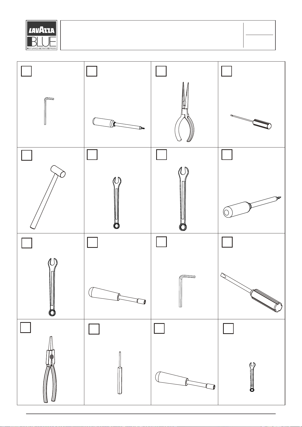
List of tools necessary for maintenance
1
6/6
3 mm Hexagonal
1
key.
Plastic hammer;
5
Tamper torx t10
2
recess male key.
12 mm spanner;
6
Long nose pliers.
3 4
7 8
15 mm spanner;
Small flat-tip
screwdriver.
Cross tip
screwdriver ph2;
14 mm spanner;
9
Pliers for seeger
13
ring;
8 mm socket
10
spanner;
Flat cotter-key
14
pusher;
5 mm Hexagonal
11
key;
7 mm Hexagonal
15
socket spanner;
Large flat-tip
12
screwdriver;
16
5.5 mm spanner.
“
“LB 1000 BLUE FAMILY”
OD. 83346 / REL. 1.00 / SEPTEMBER 2004
C
Page 9
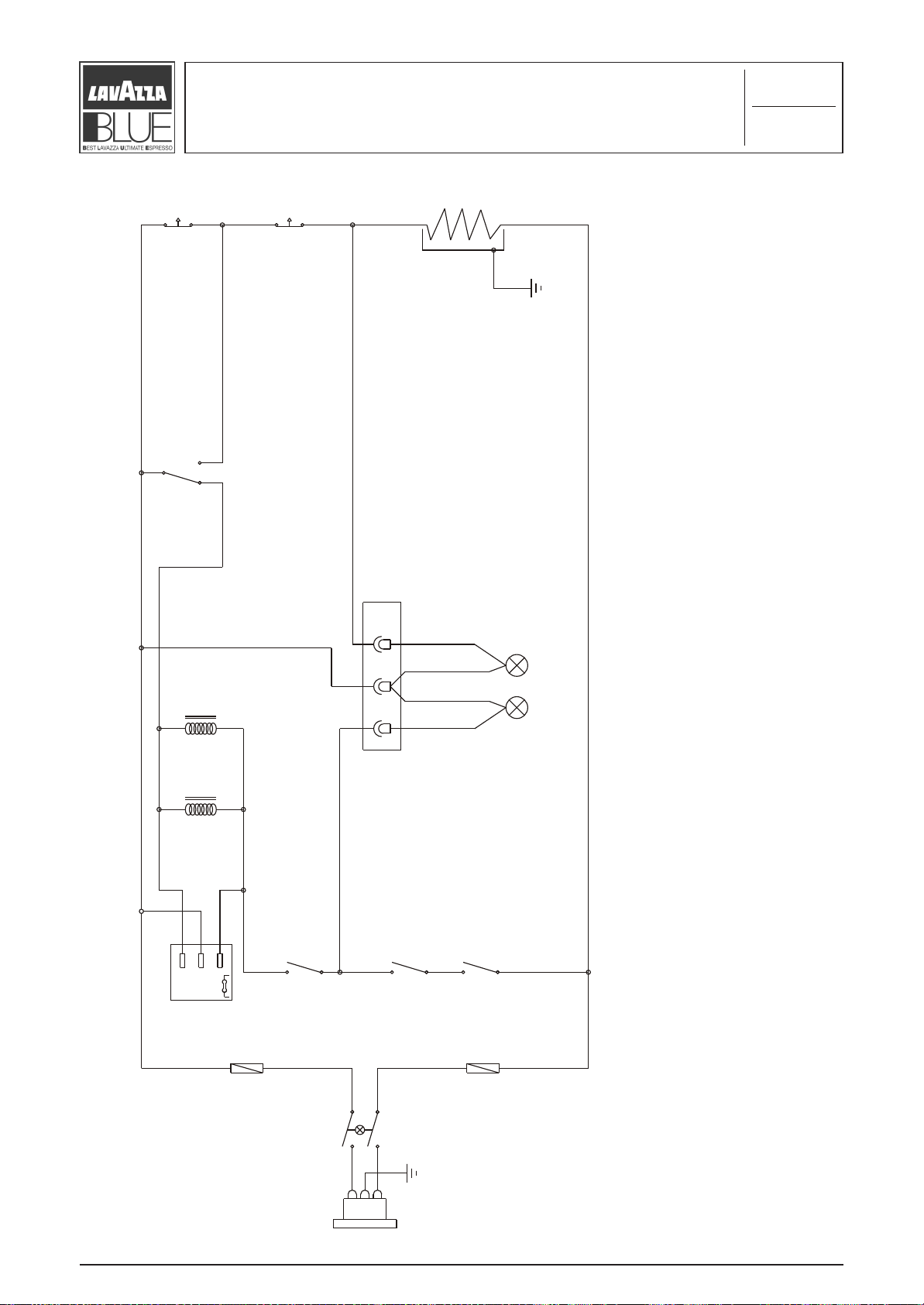
Wiring diagram
2
1/1
T 1
T 2
R 1
”
TED
H
G
I
L
E “
”
UR
T
M 4
A
R
PE
L G TE
M
Y I H D
E
D “
T
I
REA
E
N
H N
I
C I E N
A
S
CN 1
L 2
P2
L 1
H
ED M
D MAC
E
EN L
E
R
=
L1 G
T R
L
N E1
C O
A
E
E
T
IS C
A G
E
R N
C N
ON
O
R S
=
=
n =
2
L
R
C 1
P1
S E
L FU
M 1
Board
M 2
M 3
A
RM
E
H
T
FETY
A
S
F
TMF
Luminous main
N
switch
Re r plu
a
g
TMF
MF=
T
S
L
ULE
S
NTRO
P
O
A
C
R
MI
D
A
E
E
S
P
U
COVE
UMP C
R
R ST
O
FOR
WITCH
ICROS
M
M2=
F
TCH
WI
OS
R
3= MIC
M
O
F
H
T
I C
W
S
O
R
C
= M
4
M
FOR
TS
H
A
C
IT
W
R OS
CROS
I
= THE
M
2
- M T
1
T
M1=
“LB 1000 Blue Family” Rel. 00 settembre 2004
“
“LB 1000 BLUE FAMILY”
8
OD. 83346 / REL. 1.00 / SEPTEMBER 2004
C
Page 10
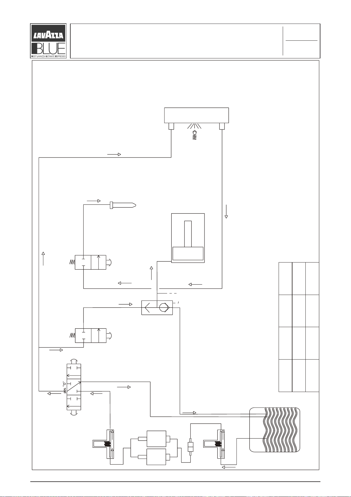
Hydraulic diagram
Heating unit
Coffee
3
1/1
Steam
Steam valve
Coffee valve
Cylinder
Open
Coffee position
knob
“0” position
knob
Close
Close
Quick-release
Steam position
knob
Close
Open Open
“Cof” pos.
Coffee
valve
Steam
valve
“Steam” pos.
Dispenser
“LB 1000 Blue Family” Rel. 00 settembre 2004
“
“LB 1000 BLUE FAMILY”
Air
Water
Vibration damping unit
Pump
Pump
9
Air
Filter
Water
Vibration damping unit
OD. 83346 / REL. 1.00 / SEPTEMBER 2004
C
Water tank
Page 11
Index of maintenance sheets
4.1 Preliminary operations of case maintenance
4.2 Hydraulic section maintenance
4.3 Electric section maintenance
4.4 Heating unit maintenance
4
1/1
4.5 Piston unit maintenance
4.6 Board frame maintenance
4.7 Frame maintenance
4.8 Micro switch maintenance
4.9 Base maintenance
“
“LB 1000 BLUE FAMILY”
OD. 83346 / REL. 1.00 / SEPTEMBER 2004
C
Page 12
Preliminary operations of
4.1
case maintenance
1/9
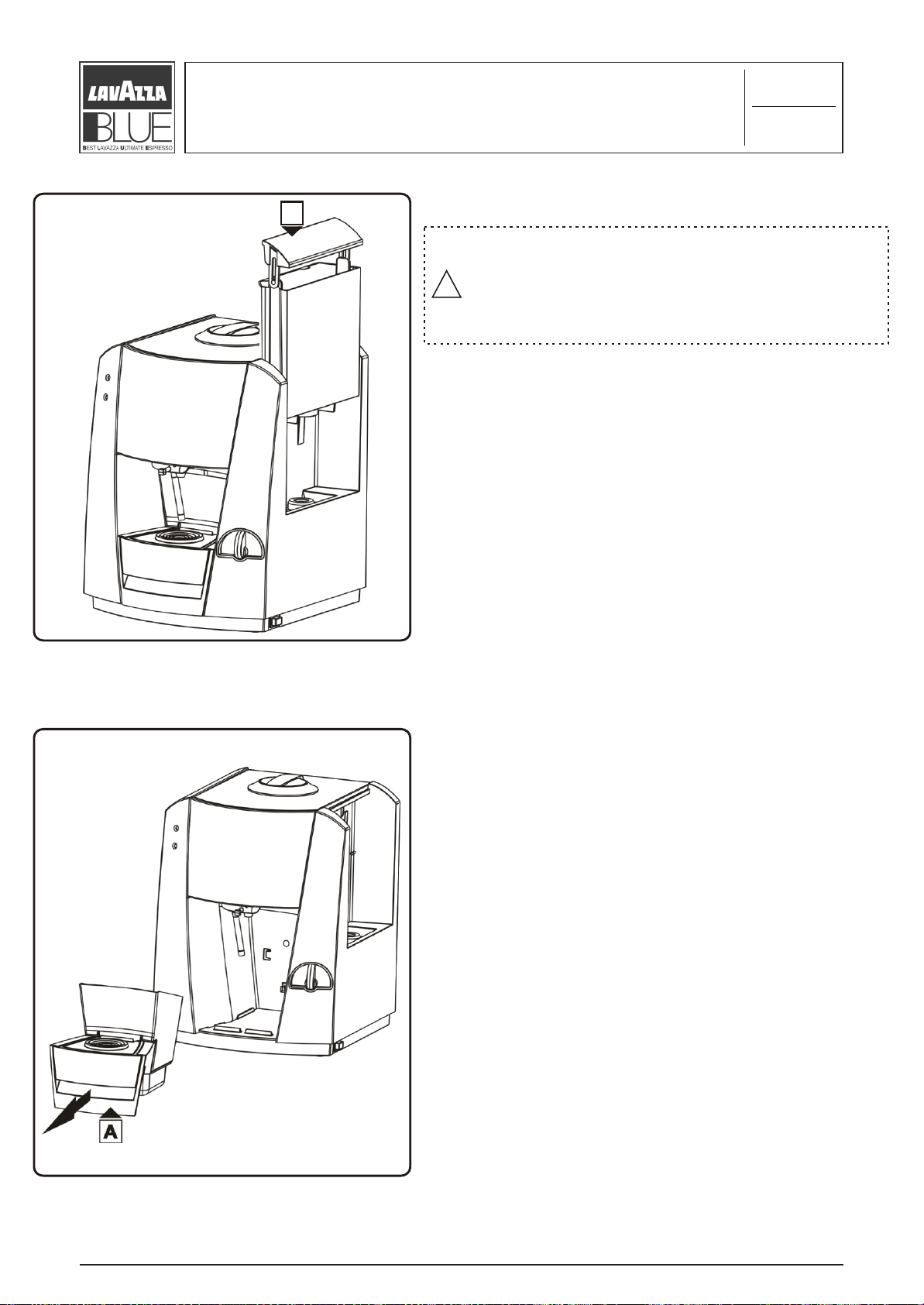
A
CAUTION
Remove plug from power outlet before any
maintenance operations!
!
Never start the machine during maintenance
operations.
Slide and remove the water tank, hold from the cover “A”
and pull upward
Remove the drop and capsule drawer, catch on the rear side
“A” and pull to the external side.
“LB 1000 Blue Family” Rel. 00 settembre 2004
“
“LB 1000 BLUE FAMILY”
11
OD. 83346 / REL. 1.00 / SEPTEMBER 2004
C
Page 13
Preliminary operations of
case maintenance
4.1
2/9
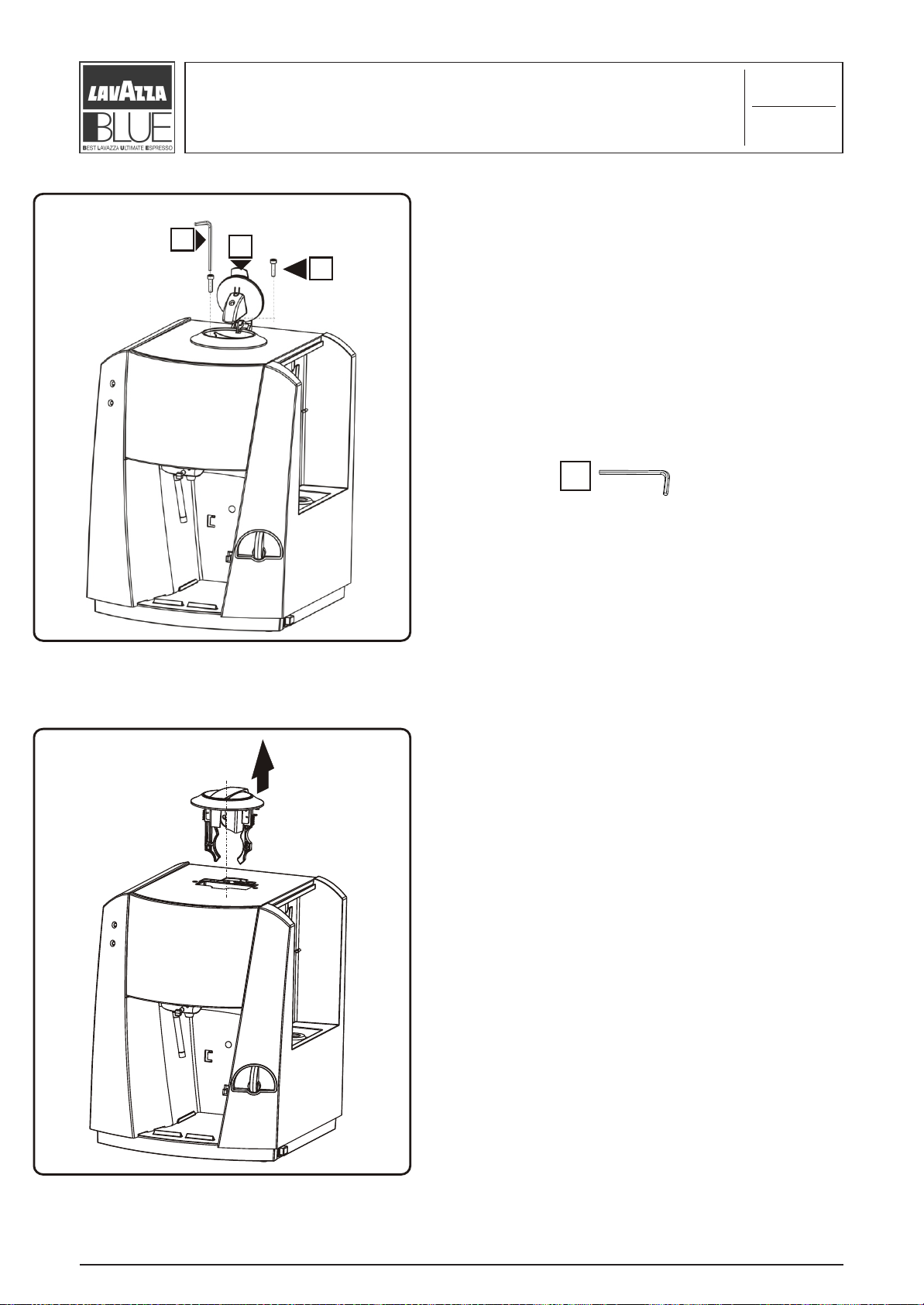
1
A
B
Open the capsule inserting cover “A” and by means of the
key “1” unscrew the two fixing screws “B”.
1
Remove by pulling up the entire capsule inserting unit.
“LB 1000 Blue Family” Rel. 00 settembre 2004
“
“LB 1000 BLUE FAMILY”
12
OD. 83346 / REL. 1.00 / SEPTEMBER 2004
C
Page 14
Preliminary operations of
case maintenance
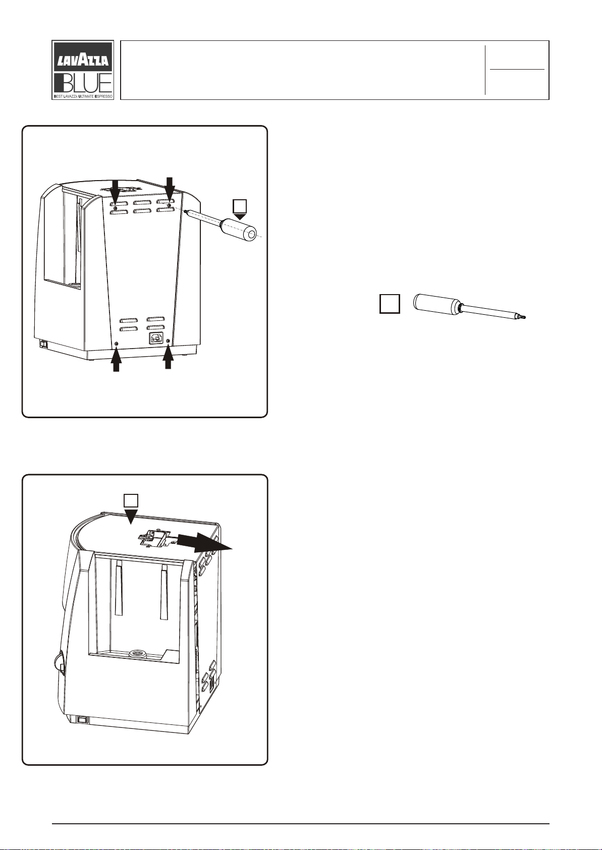
2
Unscrew the 4 screws which fix the upper
panel by torx t10 key “2”.
2
4.1
3/9
A
Remove the upper panel “A” from the seat of the
capsule inserting unit and with a light traction
pull to the machine rear following the arrow in
such a way as to release it from the frame.
“
“LB 1000 BLUE FAMILY”
OD. 83346 / REL. 1.00 / SEPTEMBER 2004
C
Page 15
Preliminary operations of
case maintenance
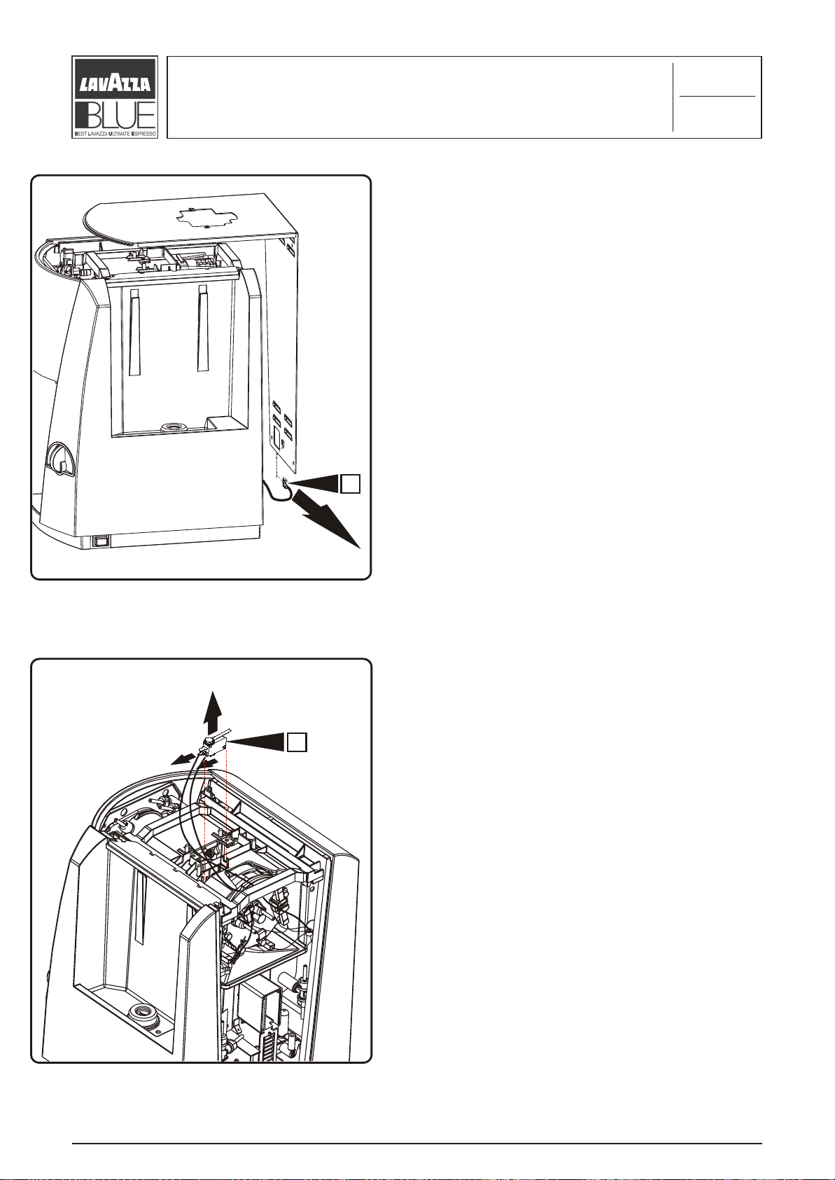
Disconnect the earthing cable “A” from the male
faston terminal on the rear panel following the
figure, now remove the entire panel.
A
4.1
4/9
A
Slide the micro switch “A” from its seat being
careful of the electric connexion.
To replace the micro switch disconnect the two
cables of the electric system.
“LB 1000 Blue Family” Rel. 00 settembre 2004
“
“LB 1000 BLUE FAMILY”
14
OD. 83346 / REL. 1.00 / SEPTEMBER 2004
C
Page 16
Preliminary operations of
4.1
case maintenance
5/9
A
B
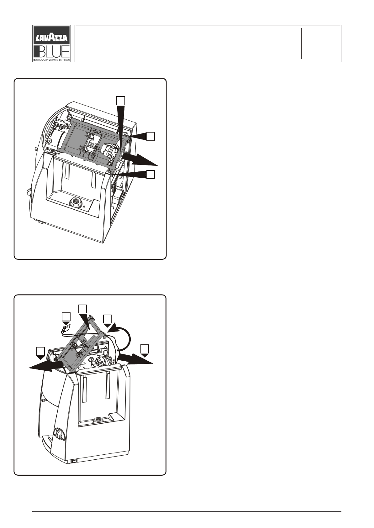
To remove the upper frame you have to hold it by
B
point “A” pull outwards to the rear of machine in
direction of the arrow, until the two fixing pins
“B” exit from their seats.
D
C
B
A
E
Make a rotation “A” of about 90° of the upper
frame; release the micro switch “C” with
relative electric system from the upper frame
passing through the hole “D” in the direction of
the arrow “E”, slide the upper frame in the
direction of the arrow “B” and remove it.
“
“LB 1000 BLUE FAMILY”
OD. 83346 / REL. 1.00 / SEPTEMBER 2004
C
Page 17
B
Preliminary operations of
case maintenance
Slide out the silicon tube “A” from the capsule
holder “B” by passing through the dispenser
space.
4.1
6/9
A
B
A
D
C
Push on the two hooks “A” right and “B” left in
the direction of the arrows, sliding the front
panel “C” in the direction “D” of about 1-2
cm. With a combined movement of sliding and
traction downwards and some little rotations,
remove the entire steam dispenser tube “D”,
now extract the front panel.
D
“
“LB 1000 BLUE FAMILY”
OD. 83346 / REL. 1.00 / SEPTEMBER 2004
C
Page 18

Preliminary operations of
4.1
case maintenance
7/9
B
A
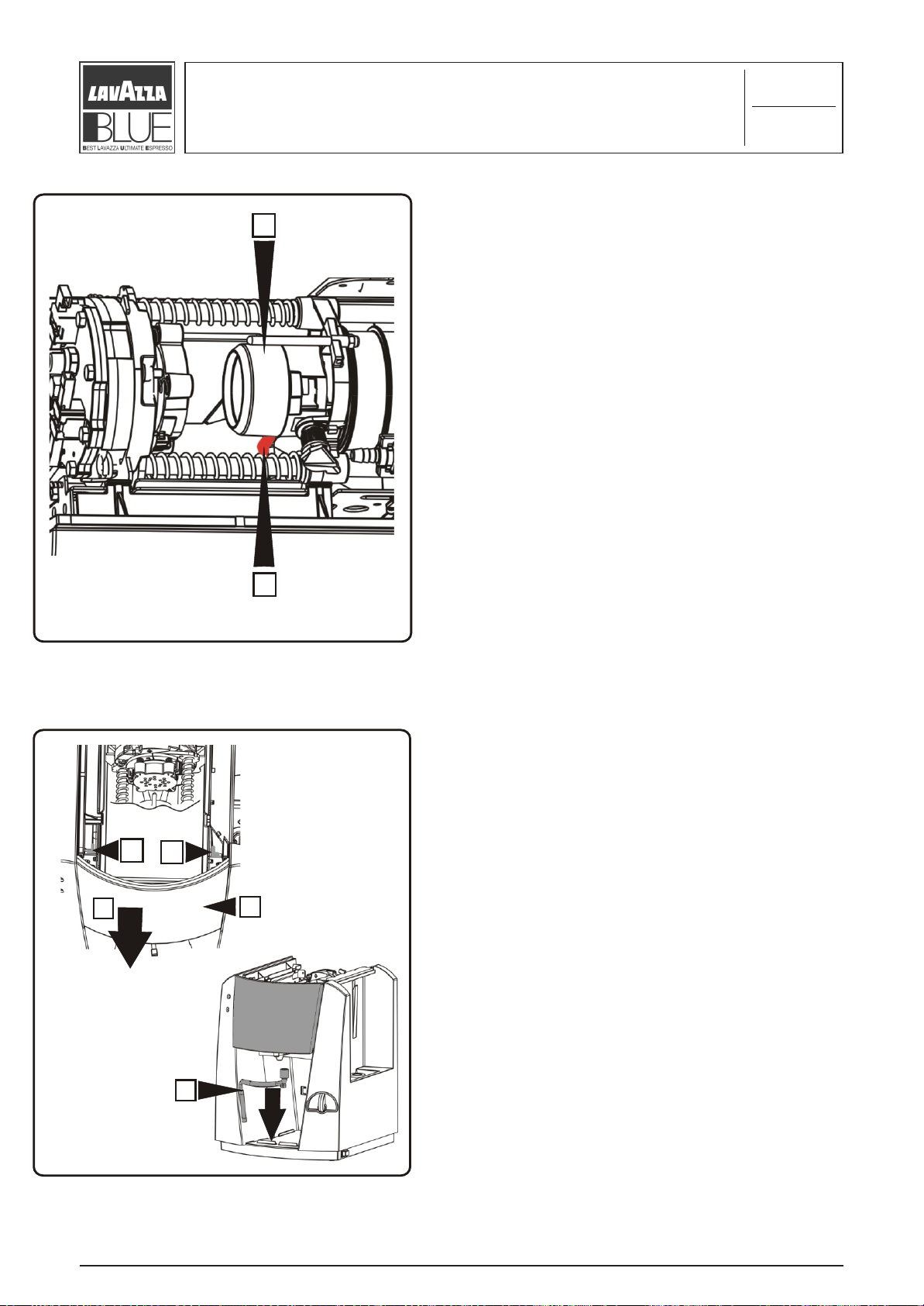
Remove the coffee distributor “A”: use a small
flat-tip screwdriver “4” and with a light traction
lift upwards.
To replace the silicone tube “B” it is
recommended to detach the distributor “A”.
4
4
3
Remove the dispenser cover “A”: use the nose
pliers “3” to release the three hooks, in
sequence “C” - “D” - “E”, and at the same time
pull it downwards towards “F”.
E
D
C
A
F
“
“LB 1000 BLUE FAMILY”
3
OD. 83346 / REL. 1.00 / SEPTEMBER 2004
C
Page 19

Preliminary operations of
4.1
case maintenance
8/9
Remove the coffee knob + joint “A”, levering
with a small flat-tip screwdriver “4” pulling it at
the same time from the handle.
A
4
4
B
C
D
Release the left side panel, hold it by “A” and “B”
points, lift upwards and at the same time
outwards, before removing it completely, it is
necessary to disconnect the two connectors of
A
the electric system “C” (led group) and “D” “led
group power supply).
“LB 1000 Blue Family” Rel. 00 settembre 2004
“
“LB 1000 BLUE FAMILY”
18
OD. 83346 / REL. 1.00 / SEPTEMBER 2004
C
Page 20

Preliminary operations of
case maintenance
Release the right side panel, hold it by “A” and
“B” points, lift upwards and at the same time
outwards, before removing it completely, it is
necessary to disconnect the silicone tube of the
hydraulic system.
B
4.1
9/9
A
A
D
Loosen the tube clip “D” from the right side panel
C
and disconnect the three silicone tubes “A” - “B” “C”.
B
“
“LB 1000 BLUE FAMILY”
OD. 83346 / REL. 1.00 / SEPTEMBER 2004
C
Page 21

4.2
Hydraulic section maintenance
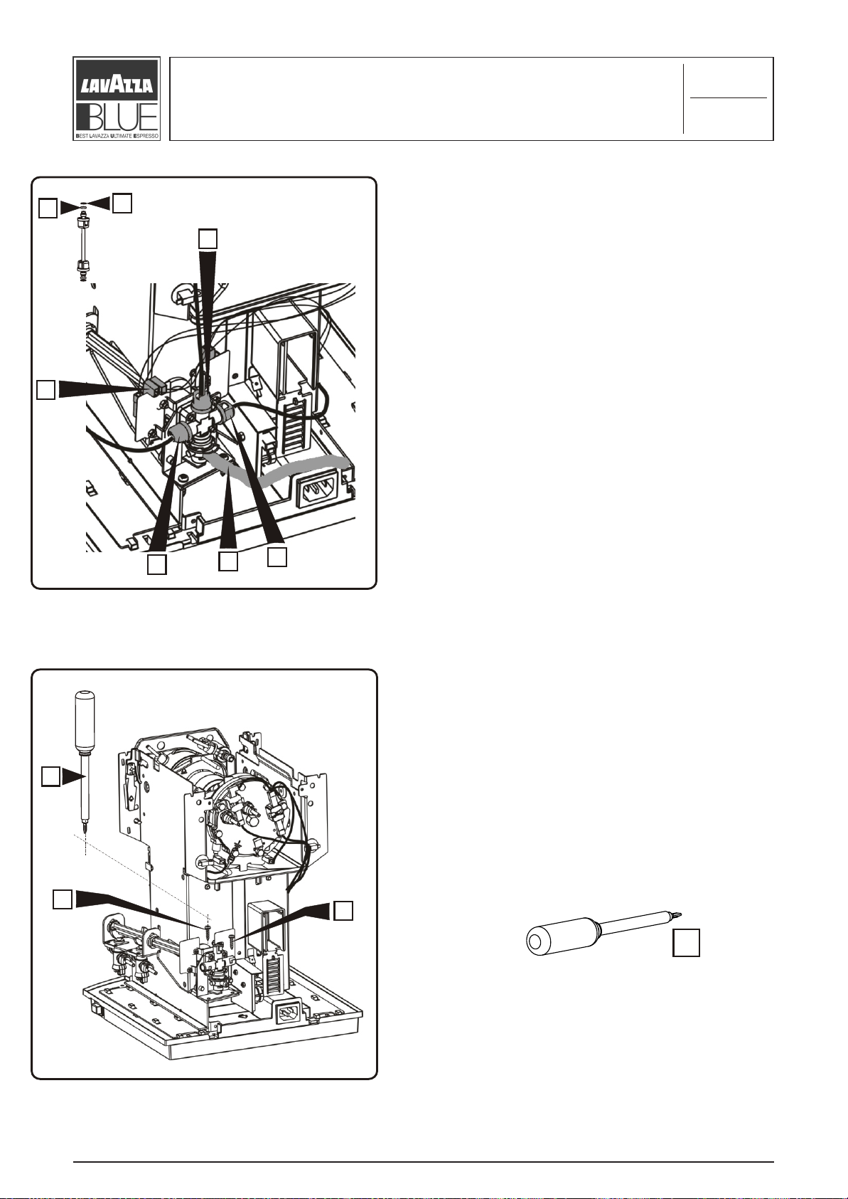
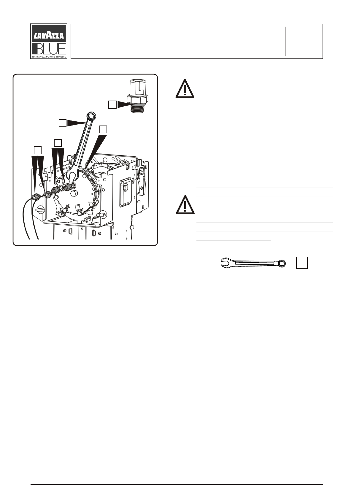
A
1/10
To remove the complete tank valve use a
plastic hammer and operate with care
exclusively on the surface indicated “A” in the
direction of the arrow.
5
5
A
X
X
4
E
D
B
F
After having removed the tank valve “A”
from the panel, if you want to replace the
joint “F” use a small flat-tip screwdriver “4”
levering on “X” points until the upper cover
valve is released and remove the joint “F”.
If you want to detach the dump valve “E D C
B”, take the complete valve “A”, by means
of the pliers “3” remove the valve “C” with
joint “D” and pin “E”, and extract the joint
C
“B”.
3
3
“
“LB 1000 BLUE FAMILY”
4
OD. 83346 / REL. 1.00 / SEPTEMBER 2004
C
Page 22
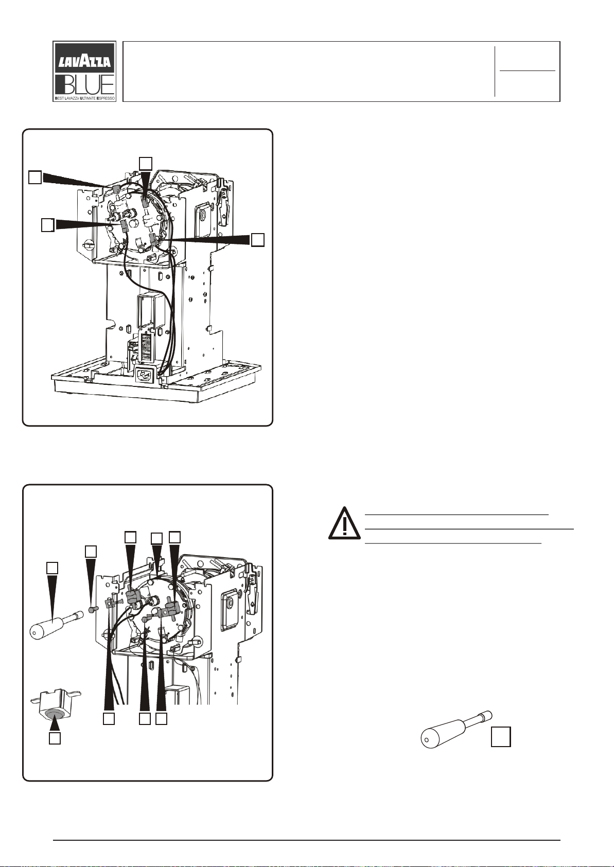
G
4.2
Hydraulic section maintenance
D
E
F
H
G
2/10
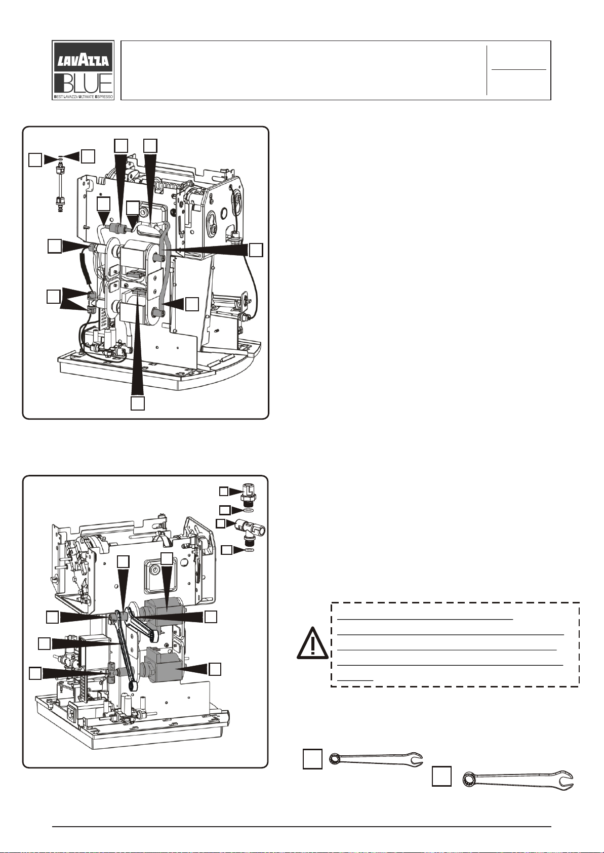
Before removing the electromagnetic pumps you
have to carry out the following operations:
- disconnect the four power faston terminals
“A”;
C
B
- disconnect the two coupling elbows “B” from
the pumps;
- disconnect the two PTFE hydraulic tubes by a
C
B
simple clockwise rotation of the three quick
couplings “C”, each tube is complete of washer
“G” and joint “F”;
- in this phase to replace the aspiration filter “D”
disconnect the silicone tubes “H” and “G”.
A
D
E1
F
To remove the pump “A” use the 12 mm
spanner “6” to clamp the pump tube “B” in
such way that it does not rotate, by means of
15 mm spanner “7” unscrew the connector “D”
B
A
F1
with its joint “E1”; to remove the pump “C”
proceed following the above description with
the only difference that you have to unscrew
the tube union “F” by hand with its joint “F1”.
D
6
Caution: to mount again the
connectors “D” - “F” it is important
7
to apply on it a clamping torque of
MAX 2,5 N x mt so as not to damage
F
C
them.
They have to be tightened until the ring nut
hits the tube and not more. If is possible
tighten by hand without the spanner.
6
“
“LB 1000 BLUE FAMILY”
7
OD. 83346 / REL. 1.00 / SEPTEMBER 2004
C
Page 23

4.2
Hydraulic section maintenance
D
A
C
3/10
Remove the pumps “A” and “B” sliding them
from the four support rubber “C” and “D” in the
direction indicated.
Note: slide before from the support “C” and then
“D”.
B
B
A
To remove the pump support bracket “A”,
unscrew the 4 screws “B” using a cross tip
8
screwdriver ph2 “8”.
“
“LB 1000 BLUE FAMILY”
OD. 83346 / REL. 1.00 / SEPTEMBER 2004
C
Page 24
4.2
Hydraulic section maintenance
Before removing the vibration damping unit, you
have to disconnect the hydraulic connections:
remove the two coupling elbows “A” and the two
PTFE tubes unscrewing the couplings “B”, each
tube contains washer and joint.
A
4/10
ABB
Remove the entire vibration damping unit “A”
unscrewing the two fixing screw “B” by means of a
A
cross tip screwdriver ph2 “8”.
8
B
“
“LB 1000 BLUE FAMILY”
8
OD. 83346 / REL. 1.00 / SEPTEMBER 2004
C
Page 25
Hydraulic section maintenance
4.2
5/10
E
D
C
Before removing the dispenser it is necessary to
carry out the following operations in this order:
- disconnect the power faston terminal “A” from
the dispenser;
A
- disconnect the silicone tube “B” from the
dispenser connector;
- disconnect the three PTFE hydraulic tube by a
simple clockwise rotation of the three quick
couplings “C”, each tube is complete of washer
“E” and joint “D”.
C
B
C
8
Unscrew the two fixing screws “A” by means of
a cross tip screwdriver ph2 “8”.
A
A
“
“LB 1000 BLUE FAMILY”
8
OD. 83346 / REL. 1.00 / SEPTEMBER 2004
C
Page 26
4.2
Hydraulic section maintenance
A
C
B
D
4
6/10
To remove the entire dispenser “A” carry out
the following operations:
Using the pliers “3” take the shaft “B” fixed to
the bracket “C” and at the same time levering
with a flat-tip screwdriver “4” until the
dispenser slides from the shaft “B” in the
direction “D”.
3
3
4
A
“LB 1000 Blue Family” Rel. 00 settembre 2004
“
“LB 1000 BLUE FAMILY”
25
OD. 83346 / REL. 1.00 / SEPTEMBER 2004
C
Page 27
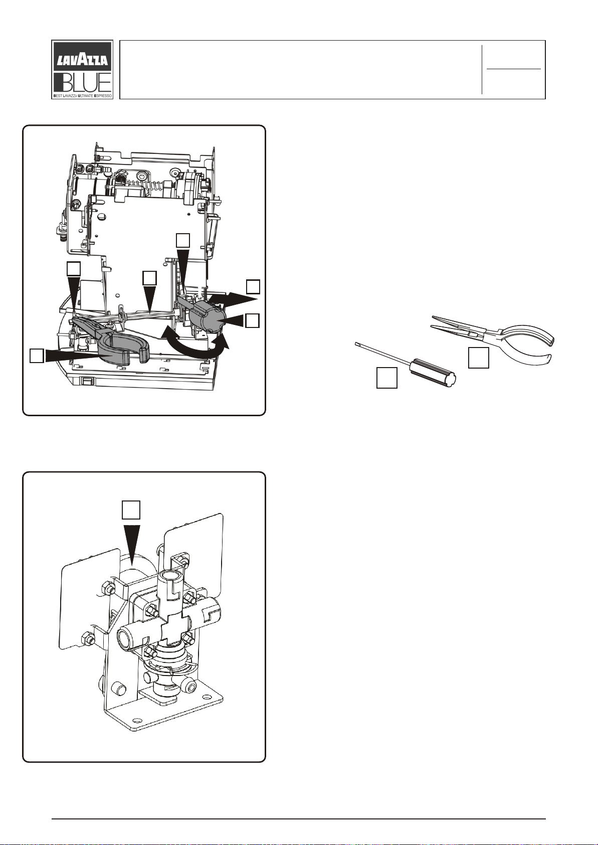
A
A
Hydraulic section maintenance
Remove by hand the two clamps “A”.
4.2
7/10
D
B
F
G
Remove the two valves “B” and “C” and
disconnect them from the relative PTFE hydraulic
tubes “D” - “E”- “F” - “G”. If you want to
disconnect only the tubes “F” - “G” slide
beforehand the valve “B” in such a way as make
the operation easier.
E
C
“
“LB 1000 BLUE FAMILY”
OD. 83346 / REL. 1.00 / SEPTEMBER 2004
C
Page 28

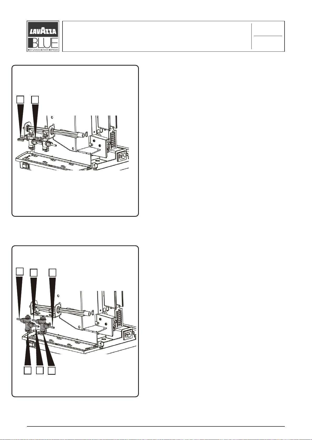
Hydraulic section maintenance
4.2
8/10
4
To remove the dispenser shaft “A” slide the
bushing “B” from its seat levering with a
small tip screwdriver “4” and use a pliers “3”
to simplify the operation.
3
3
A
B
4
“
“LB 1000 BLUE FAMILY”
Now remove completely the bushing “B” and
the shaft “A”.
OD. 83346 / REL. 1.00 / SEPTEMBER 2004
C
Page 29
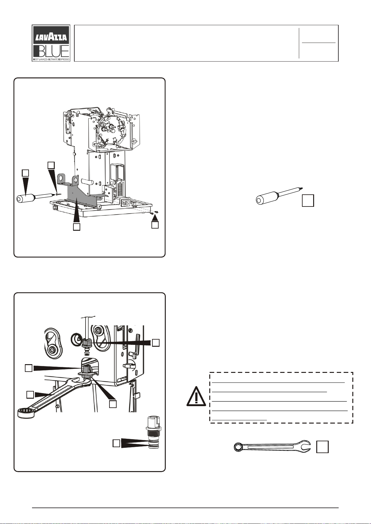
4.2
Hydraulic section maintenance
B
8
9/10
To remove the retainer “A” unscrew the 3 screws
“B” by means of a cross tip screwdriver ph2 “8”.
8
A
B
Remove the steam tube connector “A”.
Disconnect the PTFE hydraulic tube by a
simple clockwise rotation of the coupling
“B” each tube contains washer and joint,
B
unscrew the stop nut “C” using a 14 mm
spanner “9”, the connector “A” has two
joints “D”.
A
Caution: to remount the connector
“A” it is important to apply a
9
C
clamping torque of MAX 2,5 N X mt
on the nut “C” so as not to damage
the connector.
D
“
“LB 1000 BLUE FAMILY”
9
OD. 83346 / REL. 1.00 / SEPTEMBER 2004
C
Page 30
4.2
Hydraulic section maintenance
C
7
X
B
A
10/10
Caution: before performing this
operation verify that the machine is not
hot so as to avoid burning!
Keep the unit steady by hand on the point “X” to
avoid rotation, disconnect the PTFE hydraulic
tubes by a simply clockwise rotation of the two
quick couplings “A”, each tube contains washer
and joint; unscrew the two heating connectors
“B” with joint “C” by means of the 15 mm
spanner “7”.
Caution: to remount the connector
“B” it is important to apply it a
clamping torque of MAX 2,5 N x mt so
as not to damage them.
They have to be tightened until the
ring nut hits the heating plate and not
more. If possible tighten by hand
without the spanner.
7
“
“LB 1000 BLUE FAMILY”
OD. 83346 / REL. 1.00 / SEPTEMBER 2004
C
Page 31
4.3
Electric section maintenance
A
A
A
A
1/2
To replace the thermostats with the
assembled unit, beforehand disconnect them
from the 4 faston terminals “A” of the
electric system.
10
Caution: before performing this
operation verify that the machine is
A
C
D
E
CXD
B
not hot so as to avoid burning!
Keep the unit steady by hand on the point
“X” to avoid rotation, remove with the
other hand the thermostats “A” and “B”
loosening the two screws “C” by means of
8 mm hexagonal socket spanner “10”,
which fix the brackets “D”.
To remount the thermostat apply on the
lower side “E” coat silicone pulp to the
thermal conductivity.
10
“
“LB 1000 BLUE FAMILY”
OD. 83346 / REL. 1.00 / SEPTEMBER 2004
C
Page 32

Electric section maintenance
4.3
2/2
A
B
To replace the thermal fuses “A” and “B” loosen
the fixing screw “C” for thermal fuse support “D”
and disconnect the thermal fuse from the two
cables “E”.
C
Termofusibile
“E”
“
“LB 1000 BLUE FAMILY”
D
“E”
OD. 83346 / REL. 1.00 / SEPTEMBER 2004
C
Page 33
Heating unit maintenance
4.4
1/6
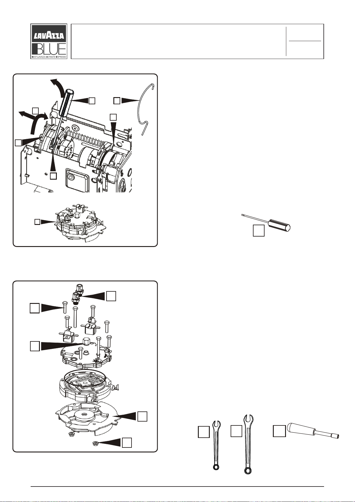
4
C
A
B
A
B
It is possible to disassemble the unit section per
X
section. To disassemble the heating unit “A”
disconnect beforehand all the electric (faston
terminals) and hydraulic connections of the
heating unit, after that, release the spring “B”,
levering with a small flat-tip screwdriver “4”,
now keeping the unit steady with one hand,
approximately on the “X” point, rotate the
heating unit “A” with the other hand in the
direction of the arrow “C” . At this point it is
completely removed.
4
A
C
B
D
E
To disassemble the heating unit completely
perform the following operations:
Unscrew the two nuts “D” by means of a 8 mm.
hexagonal socket spanner “10” and remove the
lower plate “E”.
Unscrewing the screws “A” by the 8 mm
hexagonal socket spanner “10”, it is possible to
remove the thermostat brackets, the
thermostats, the thermal fuse support, the
earthing male faston terminal and the washer.
Unscrew the two connectors “B” by means of
the 15 mm spanner “7”;
Unscrew the heating clamping nut “C” using the
12 mm spanner “6”.
6
7
10
“
“LB 1000 BLUE FAMILY”
OD. 83346 / REL. 1.00 / SEPTEMBER 2004
C
Page 34

A
Heating unit maintenance
Caution: the unit “A” can be also slid before the
complete heating unit is removed.
To remove the injection group “A” from the
assembled unit rotate it with one hand in the
direction of the arrow.
4.4
2/6
A
C
B
By means of the proper tool “A” exert a downward
pressure on the presser capsule “B” until the
stroke end signalled by the exit of the points “C”.
“
“LB 1000 BLUE FAMILY”
OD. 83346 / REL. 1.00 / SEPTEMBER 2004
C
Page 35

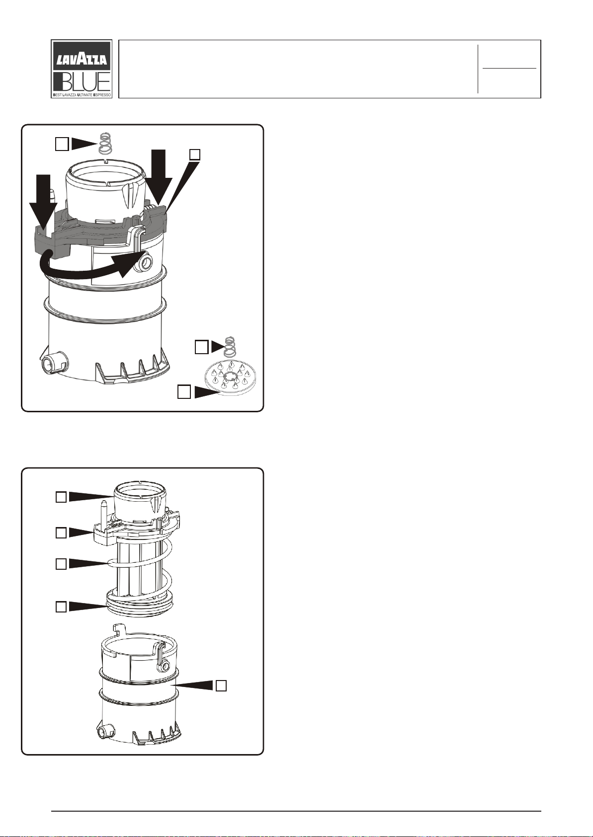
Heating unit maintenance
Keeping steady the upper part, rotate it the lower
ring “A” in a clockwise direction until the stroke
end as shown in the figure.
4.4
3/6
A
B
F
H
A
C
D
E
G
Now you can disassemble the capsule presser
completely removing in this order :
- capsule presser “A” with 4 springs “B”;
- puncher “C”;
- joints “D-E”;
- spring “F”;
- joint “G”;
- valve “H”;
- ring “”I”.
I
“
“LB 1000 BLUE FAMILY”
OD. 83346 / REL. 1.00 / SEPTEMBER 2004
C
Page 36

Heating unit maintenance
4.4
4/6
C
B
D
To remove the release valve “A” pull it from the
fixing seat “D” in the direction of the arrow and
disconnect the PTFE hydraulic tubes with a simply
clockwise rotation of the two quick couplings “B”,
each tube is equipped with washer and joint, and
the silicone tube “C”.
A
A
“
“LB 1000 BLUE FAMILY”
OD. 83346 / REL. 1.00 / SEPTEMBER 2004
C
Page 37

4.4
Heating unit maintenance
A
5/6
Valid until the serial number 36.499
Remove the assembled piston. With one hand
turn the unit in the direction of the arrow “A”
until the complete release “B” at this point you
can slide the unit through the rear side.
B
“
“LB 1000 BLUE FAMILY”
OD. 83346 / REL. 1.00 / SEPTEMBER 2004
C
Page 38

4.4
Heating unit maintenance
Valid from the serial number 36.500 onwards
A
6/6
Remove the assembled piston. With one hand
turn the unit in the direction of the arrow “A”
until the complete release “B” at this point you
can slide the unit through the rear side.
B
“
“LB 1000 BLUE FAMILY”
OD. 83346 / REL. 1.00 / SEPTEMBER 2004
C
Page 39

Piston unit maintenance
Valid until the serial number 36.499
A
To remove the assembled piston unscrew
using a 5 mm hexagonal key “11” the two
fixing screws “A”
4.5
1/10
11
11
B
A
Slide the unit support plate “A” and the two
springs for column “B”.
“
“LB 1000 BLUE FAMILY”
OD. 83346 / REL. 1.00 / SEPTEMBER 2004
C
Page 40

11
Piston unit maintenance
Valid from the serial number 36.500 onwards
A
To remove the assembled piston unscrew
using a 5 mm hexagonal key “11” the two
fixing screws “A”
4.5
2/10
11
A
Remove by hand the piston “A” from the
support “B”.
B
“
“LB 1000 BLUE FAMILY”
OD. 83346 / REL. 1.00 / SEPTEMBER 2004
C
Page 41

4.5
Piston unit maintenance
A
3/10
Valid until the serial number 36.499
Remove by hand the support plate +
columns unit “A”.
A
“
“LB 1000 BLUE FAMILY”
Remove by hand the cylinder “A” with
piston and joint.
OD. 83346 / REL. 1.00 / SEPTEMBER 2004
C
Page 42
Piston unit maintenance
4.5
4/10
B
A
To remove the spring “B” release it from
the three puncher pins “C” rotating in a
counter clockwise direction.
Make a pressure by hand on the cylinder
cap “A” and at the same time turn in
counter-clockwise direction until its
complete release.
B
C
Valid from the serial number 36.500 onwards
A
B
C
Remove by hand the piston “A” with
the cap “B”, spring “C” and joint “D”
D
E
from the cylinder “E”.
“
“LB 1000 BLUE FAMILY”
OD. 83346 / REL. 1.00 / SEPTEMBER 2004
C
Page 43

4.5
Piston unit maintenance
A
3
5/10
Valid until the serial number 36.499
Remove the piston “A” from the cylinder “B”
using the pliers “3” hold as shown in the figure
and pull towards yourself until its complete
extraction, the piston is equipped with a joint
“C”.
B
C
“
“LB 1000 BLUE FAMILY”
A
OD. 83346 / REL. 1.00 / SEPTEMBER 2004
C
Page 44

Piston unit maintenance
Valid from the serial number 36.500 onwards
4.5
6/10
A
C
Remove by hand the cap “A” making an
upwards pressure in the zone “B” in such way
as to release it from the connector “C”, now it
should be completely released and you can
remove it from the top.
B
You can also remove the spring “D” and the
joint “E”.
A
D
E
“
“LB 1000 BLUE FAMILY”
OD. 83346 / REL. 1.00 / SEPTEMBER 2004
C
Page 45

4.5
Piston unit maintenance
A
7/10
Valid until the serial number 36.499
12
X
Y
Remove the front capsule holder “A”.
Beforehand levering with a large flat-tip
screwdriver “12” on the hooking zones “X” and
“Y” until the release and turn it by hand in the
“B” position until its complete release, now you
can remove it pulling it from the top.
B
“
“LB 1000 BLUE FAMILY”
OD. 83346 / REL. 1.00 / SEPTEMBER 2004
C
Page 46

Piston unit maintenance
4.5
8/10
B
A
C
Valid until the serial number 36.499
Remove the puncher “A” with the spring “B” and
the joint “C”; to remove the spring “B” from its
seat rotate it by hand in ae counter-clockwise
direction in such way to release it from the
three fixing pins “D”.
B
D
D
D
13
Using the nose pliers “13” remove the seeger
ring “A”.
A
“
“LB 1000 BLUE FAMILY”
13
OD. 83346 / REL. 1.00 / SEPTEMBER 2004
C
Page 47

4.5
Piston unit maintenance
A
B
C
9/10
Valid until the serial number 36.499
Make a pressure by hand on the support pin
capsule holder from side “A” until you can
release the spring “B” from its seat “C”
always by hand.
B
X
Remove the pin “A” with its spring “B”, lock
14
5
the piston “C” in a vice and making a light
pressure on the “X” point by the cotter key
pusher “14” and the hammer “5” until the pin
exits from the opposite side of 2-3 cm, after
that remove it completely by hand.
A
C
“
“LB 1000 BLUE FAMILY”
5
OD. 83346 / REL. 1.00 / SEPTEMBER 2004
C
14
Page 48

4.5
Piston unit maintenance
A
B
C
10/10
Valid until the serial number 36.499
At this point you have removed the pin with
its spring “A”, the rear capsule holder “B”
and the piston support “C”.
A
B
3
15
Remove the lock pin “A”. Unscrew the nut
“B” by means of the 7 mm hexagonal socket
spanner “15” keeping steady the pin “A” with
the pliers “3”.
3
15
“
“LB 1000 BLUE FAMILY”
OD. 83346 / REL. 1.00 / SEPTEMBER 2004
C
Page 49

Board frame
maintenance
4
4.6
1/1
Open the support board cover “A” levering with
the small flat-tip screwdriver “4” and remove
the board “B” now you can disconnect from the
board the three electric contacts “C”.
B
C
Disconnect the earthing faston terminal from
the frame “D” and the electric contact from the
micro switch of the drawer “E”.
D
4
E
D
A
A
Remove the frame “A”. Pushing the frame from
the rear side in the direction of the “x” arrow,
press down alternatively the fin “B” and “D”
Y
X
using a flat-tip screwdriver “12”, slide the
frame in the “X” direction, now you can
remove it lifting it to the top in the “Y”
direction.
12
“
B
“LB 1000 BLUE FAMILY”
12
OD. 83346 / REL. 1.00 / SEPTEMBER 2004
C
Page 50

Frame maintenance
4.7
1/1
A
4
Removing the dispenser unit “A”. Using a
small flat-tip screwdriver “4” levering on the
four fin “B” alternatively until their release
from the frame and then remove the
compartment “A” sliding it in the arrow
direction.
B
4
A
B
X
C
A
X
8
C
Remove from the frame the two hooks “A” and
“B”, unscrew the two screws “C” by means of a
cross tip screwdriver ph2 “8” and make a
pressure on the hook on the surface indicated
by the “X” to extract it completely.
“
“LB 1000 BLUE FAMILY”
8
OD. 83346 / REL. 1.00 / SEPTEMBER 2004
C
Page 51

Micro switch
maintenance
4.8
1/2
Removing the board drawer “A”. Using a large
flat-tip screwdriver “12”, unhook, by a light
pressure, the two frame fixing hooks “B”.
A
Now the frame is empty of components.
12
A
B
12
“
“LB 1000 BLUE FAMILY”
OD. 83346 / REL. 1.00 / SEPTEMBER 2004
C
Page 52

Micro switch
maintenance
4.8
2/2
16
B
8
To disassemble the dispenser compartment you
have to carry out the following operations:
Remove the micro switch “A” from the
compartment “B” unscrewing the two fixing
A
D
C
screws “C” by means of a cross tip screwdriver
ph2 “8” and 5,5 mm spanner “16” for the nuts
“D”. Unscrew the fixing screw “E” using the
screwdriver “8” remove the spring “F” the came
for micro adjustment “G” and the spring “H”.
8
H
F
G
E
8
16
“
“LB 1000 BLUE FAMILY”
OD. 83346 / REL. 1.00 / SEPTEMBER 2004
C
Page 53

4.9
Base maintenance
1/2
4
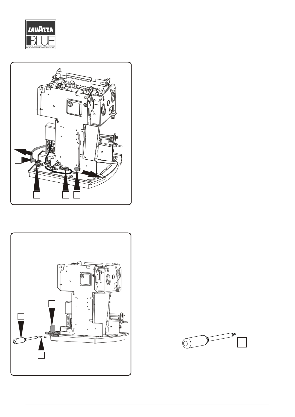
Remove the connector for the power cord “A”
from seat “B” levering with a small flat-tip
screwdriver “4”, and disconnect the three
power faston terminals “C”, after this you can
remove it.
A
C
B
4
B
Disassembling the base. Unscrew the fixing
screw “A” with a cross tip screwdriver ph2 “8”
and using a small flat tip screwdriver “4”
4
A
8
C
levering on the retaining hooks “B”.
8
4
“
“LB 1000 BLUE FAMILY”
OD. 83346 / REL. 1.00 / SEPTEMBER 2004
C
Page 54

4.9
Base maintenance
2/2
A
B
Remove the 4 power faston terminals “A” from
the main switch “B” now you can detach the
switch from the upper base “C”.
C
B
“
“LB 1000 BLUE FAMILY”
OD. 83346 / REL. 1.00 / SEPTEMBER 2004
C
 Loading...