

Page 1
Page 2

THIS EQUIPMENT COMPLIES WITH FCC REQUIREMENTS
This device complies with Part 15 of the FCC Rules. Operation is subject to
the following two conditions: (1) this device may not cause harmful
interference, and (2) this device must accept any interference received,
including interference that may cause undesired operation.
WARNING: Changes or modifications to this product not expressly approved by
the party responsible for compliance could void the user’s authority to operate this
equipment.
NOTE: This equipment has been tested and found to comply with the limits,
pursuant to Part 15 of the FCC Rules. These limits are designed to provide
reasonable protection against harmful interference in a business installation. This
equipment generates, uses, and can radiate radio frequency energy and, if not
installed and used in accordance with the instructions, may cause harmful
interference to radio communications. However, there is no guarantee that
interference will not occur in a particular installation. If this equipment does cause
harmful interference to radio or television reception, which can be determined by
turning the equipment off and on, the user is encouraged to try to correct the
interference by one or more of the following measures:
- Reorient or relocate the receiving antenna.
- Increase the separation between the equipment and receiver.
- Connect the equipment into an outlet on a circuit different from that to which
the receiver is connected.
- Consult the dealer or an experienced radio TV technician for help.
This Class A digital apparatus complies with Canadian ICES-003.
Cet appariel numerique de la classe A est conforme a la norme NMB-003 du
PURSUANT OF PART-15
Canada.
Lathem Time Corporation
200 Selig Drive, SW,
Atlanta, GA 30336
www.lathem.com
Copyright © 2017 Lathem Time Corporation. All rights reserved.
Revised 04-26-2018
Document number: USG0114A
Page 3

Contents
Welcome 1
Package Contents ......................................................................... 4
Install the PC700 Series Clock ..................................................... 5
PayClock Online 8
Adding a PC700 series clock ........................................................ 8
Step 1 - Adding the PC700 series clock ..................................... 8
Step 2 - Connect the Clock to PayClock Online......................... 9
Changing settings at the Clock ................................................... 10
How do I change the time zone? .............................................. 10
How do I disable daylight savings? .......................................... 11
How do I change the displays time format? ............................. 11
Changing settings from PayClock ............................................... 11
How do I change the time zone? .............................................. 11
How do I disable daylight savings? .......................................... 12
How do I change the displays time format? ............................. 12
How do I disable PIN entry for all employees? ........................ 12
How do I disable Badge entry for all employees? .................... 13
How do I disable amount entry for all employees? .................. 13
How do I disable transfers for all employees? ......................... 14
Using the PC700 Series Clock 15
PC700 Series Clock Idle Screen................................................. 16
Employee Transactions using Badges ....................................... 16
Clocking IN/Out ........................................................................ 16
Department Transfers .............................................................. 16
Amount Entries ......................................................................... 17
Viewing Totals .......................................................................... 17
Employee Transactions using a PIN ........................................... 17
Clocking IN/Out ........................................................................ 17
Department Transfers .............................................................. 18
Amount Entries ......................................................................... 18
Viewing Totals .......................................................................... 18
Supervisor Transactions ............................................................. 19
Viewing Punches ...................................................................... 19
Contents • iii
Page 4

Adding Punches ....................................................................... 19
Viewing Totals .......................................................................... 20
Send Message ......................................................................... 20
Override Lockout ...................................................................... 21
Settings - Set/Change PIN ....................................................... 21
Settings - View/As s ign Badge .................................................. 22
Administrator Functions .............................................................. 23
Sync Now ................................................................................. 24
Device Information ................................................................... 24
Network Setup - Clock Settings................................................ 24
Date/Time Setup - Date ............................................................ 26
Error Log ................................................................................... 27
Relay Settings .......................................................................... 28
Test Connection ....................................................................... 28
Reset .................................................................................... 29
Troubleshooting the PC700 Series Clock 30
General Troubleshooting ............................................................ 30
PC700 Series Troubleshooting ................................................... 30
Appendix A – Testing the Connection to PayClock
Online 32
Appendix B - Bell Relay Connections 34
Appendix C - Access Relay Connections 39
Appendix D - Add/Edit/Delete Bell Events 41
Glossary of Terms 43
Index 45
iv • Contents
Page 5

Welcome
Reliability, functionality and ease of use are trademarks of the
PayClock clocks. With the PC700 clock, employees can use a badge
or PIN to punch in and out, view messages or benefit time balances
– it’s that simple. In addition, the PC700 contains an on-board relay
which can be used to control bells/signaling devices, or security
access.
The PayClock software and PC700 series clocks are the perfect
solution for businesses that want to track employee time and
automate payroll.
The clock utilizes a powerful Windows CE based appli c ation and a
touch-panel display for inputting data by employees, supervisors or
administrators. The clock validates that the employee is in the
database before recording the transaction.
The clock offers a large color LCD touch-panel that displays
employee information along with an audio prompt. Upon a
successful transaction, the display will show the employee’s name,
total worked time, In / Out status and an audio/text prompt.
The PC700 series clocks is used with the PayClock Online product.
The PayClock Online product is in the cloud with the clock
communicating with PayClock Online over the internet.
The PC700 clock can be connected directly into a wall Ethernet jack
or to a wireless network for communications with the PayClock time
and attendance software.
Welcome • 1
Page 6

Clock Features and Specifications
• Windows CE 6.0 - The power of embedded Windows CE to
provide fast and dependable operation.
• LCD Color Touch-Panel - Use the large easy to read touch-
panel for set up and data entry.
• On-Board Relay - The on-board relay can be used to control
bells/signal devices, or security access.
• The PC700 clock has an integrated antenna and is
compliant with the IEEE 802.11a/b/g standard. It supports
WEP, WPA and Open authentication.
• PC700 series Idle Screen - Easy to read time/date screen
will display after 2 minutes of inactivity on the clock.
• User friendly design - Large easy to read touch-panel.
• Comprehensive support agreements minimize technical
difficulties.
• Numerous Accessory options further enhance the
functionality of your PC700 series clock.
Accessories
Accessories are offered to further enhance your PayClock system.
Visit http://shop.lathem.com to purchase additional accessories like
the ones listed below.
• Badges
• Badge Racks
Getting Help
You can access the help desk and answers to your issues in several
different ways. In addition to resources within the PayClock
software, assistance may be accessed online, via email, via
telephone, or through your dealer .
PayClock Help
The Online Help allows you to search through an index of help topics
to locate the answer you need.
2 • Welcome
Page 7

Troubleshooting
For answers to Frequently Asked Questions, refer to the
Troubleshooting section of this User Guide.
Online and Email Support
Lathem.com provides access to numerous support resources. Visit
the following link: http://kb.lathem.com
for additional help or to submit
a question. You should receive a reply within 24 hours.
Telephone Support
The help desk is available between the hours of 8am and 6pm ET
Monday through Friday. Please call (800) 224-1877 to speak with
our help desk.
Welcome • 3
Page 8
Package Content s
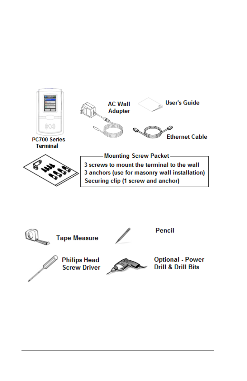
Please verify that your package includes ALL of the following items.
If your package is missing an item, please call our help desk at (800)
224-1877.
Recommended Installation Tools
4 • Welcome
Page 9
Install the PC700 Series Clock
Step 1: Select a site to install your clock that will be convenient to
employees clocking in and out. When deciding where the clock will
be installed, keep in mind that an 115vAC power outlet should be
within reach of the mounting location as well as a connection to the
network (LAN).
Note: It is recommended to install and mount the clock before
installing the PayClock software. With the clock powered up and
connected to the network (LAN), the software will search for it on the
network and automatically configure the clock.
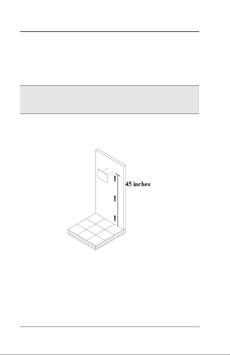
Step 2: After selecting the appropriate installation site, use masking
tape to hold the included Mounting Template onto the wall. Drill holes
using the template as a guide. Note: the bottom of the clock should
be about 45 inches from the floor.
Remove the Template from the wall and install the included
mounting screws. Ins ta ll t he three larger scr ews, leav i ng
approximately 3/16 inch of the screws exposed. Do not tighten all
the way. Retain the smaller screw for later.
Note: For sheetrock walls, drill a 3/16” diameter hole through each of
the four screw locations; each approx 1-1/2” deep. Install the plastic
“anchors” included in the mounting screw packet.
Welcome • 5
Page 10
Master
Step 3: Network Connection – Wi-Fi or Wired
Wi-Fi Connection: With the power adapter connected and the clock
mounted to the wall follow these steps to configure the Wi-Fi
connection. Note: The Wi-Fi option is enabled by default.
• From the PC700 touchpad press the Admin button. Enter the
administrator password and press Enter.
• The Administrator Main Menu screen will display.
• Press Network Setup. The Network Setup screen will
display.
• Press WiFi. The PC700 will check to see if there are any Wi-
Fi connections within range and display them in a list. Note:
Make sure the WiFi Enabled is set to Yes.
• Select the desired Wi-Fi connection from the list.
• The Enter Passcode screen will disp lay with a keypad.
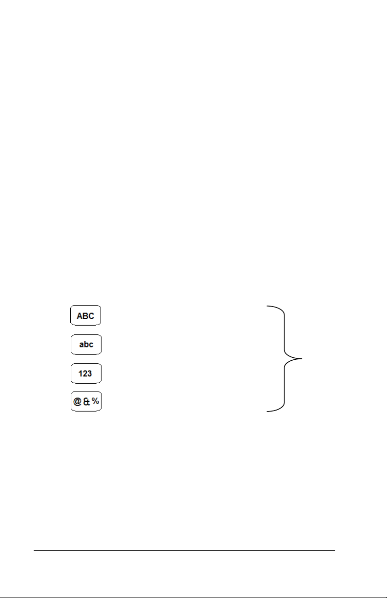
• Using the master buttons to select upper case letters, lower
case letters, numbers or symbols enter the passcode for the
wireless network. Note: You may need to contact your
network administrator for the wireless passcode information.
Use this button for upper case letters.
Use this button for lower case letters.
Buttons
Use this button for numbers.
Use this button for symbols.
• Press OK. A confirmation m essage will disp lay when the
PC700 is connected, press OK.
• When finished press the back button unti l you have
returned to the home screen.
6 • Welcome
Page 11
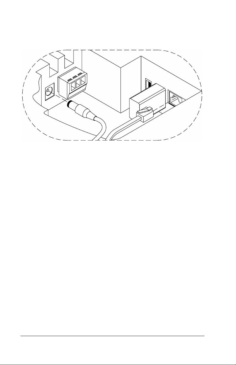
Wired Connection: Plug the RJ45 network cable into the Ethernet
port and the Power Adapter plug into the Power Adapter port which
is in the compartment on the back of the clock. See drawing below.
Insert the small “L”-shaped security bracket into the slot at the
bottom-rear of the clock, so that the tab with the hole points
downward.
Hang the clock on the wall, align ing the three k e yholes on the rear of
the enclosure with the three protruding screw heads, and then
pressing downward on the clock housing until it lowers onto the
screws.
Screw the small Screw into the hole of the tab from the small “L”shaped bracket at the bottom of the enclosure. This will fasten the
clock to the wall, and keep it from being easily removed.
When finished, plug the power adapter into an AC wall outlet.
You are now ready to sync the PC700 clock once it is set up in the
PayClock Online software
Welcome • 7
Page 12

PayClock Online
The PayClock Online product is in the cloud and communicates with
the clock over the internet.
Adding a PC700 series clock
Adding a PC700 series clock to PayClock Online is a 2-step process.
Add the clock in PayClock Online first and then from the clock
connect to the hosted database.
Step 1 - Adding the PC700 series clock
The PC700 series clock must be added to PayClock Online first
otherwise the connection will fail.
• Log into PayClock Online and go to Clocks>Manage Clock s
in the navigation list.
• Click New and the Select Clock Type window will open.
• Select PC700 from the drop-down list and click OK.
• The clock properties will display on the right.
• Then enter a name for the clock under Device Nickname.
• From the General tab enter the serial number of the clock.
Note: Enter the serial number exactly as it shows on the
label on the clock.
• Click Save.
8 • PayClock Online
Page 13

Step 2 - Connect the Clock to PayClock Online
The PC700 series clock must be added to PayClock Online before
attempting this step. The clock must be powered up and connected
to the network with access to the internet.
• At the PC700 press the Admin button. Enter the
administrator PIN and press Enter.
• Press Sync Now, the clock will connect over the internet to
PayClock Online.
• After connecting the data will be downloaded to the clock
and it will be ready for use.
• When complete a gree n ico n
display ident ifying it is to the internet.
• The clock will be operational and ready for use.
will show on the clock’s
PayClock Online • 9
Page 14

Changing settings at the Clock
The default settings that can be changed by the administrator at the
clock or the PayClock Online software are:
• Time Zone: The time zone is set to Eastern Time.
• Daylight Savings Time: Daylight savings is turned on.
• Time Format: The display will show the hours in a 12-hour
(AM/PM) format.
The default settings that can only be changed through the PayClock
Online software are:
• PIN Entry: PIN entry is turn on.
• Badge Entry: Badge entry is turned on.
• Allow Amounts: Amount entry is turned on.
• Maximum days to store registrations on clock: Is set to 90
days.
• Send Date/Time on poll or update: Is turned on.
• Send worked hours and benefit time after poll: Is turned on.
How do I change the time zone?
• From the clock touchpad press the Admin button. Enter the
administrator password (PIN) and press the Enter button.
• The Administrator Main Menu screen will display.
• Press Date/Time Setup. The Date Setup screen will display.
• Press the Time Zone button. The Choose Time Zone screen
will display.
• Using the up and down arrow keys select the desired time
zone and click OK.
• When finished press the back button unti l you have
returned to the default screen.
10 • PayClock Online
Page 15

How do I disable daylight savings?
• From the clock touchpad press the Admin button. Enter the
administrator password (PIN) and press the Enter button.
• The Administrator Main Menu screen will display.
• Press Date/Time Setup. The Date Setup screen will display.
• Under Daylight Save Time press Off.
• The screen will refresh with the newly selected option.
• When finished press the back button unti l you have
returned to the default screen.
How do I change the displays time forma t ?
• From the clock touchpad press the Admin button. Enter the
administrator password (PIN) and press the Enter button.
• The Administrator Main Menu screen will display.
• Press Date/Time Setup. The Date Setup screen will display.
• Under Time Display Format press either the 12HR or 24HR.
• The screen will refresh with the newly selected option.
• When finished press the back button unti l you have
returned to the default screen.
Changing settings from PayClock
How do I change the time zone?
• Log into PayClock Online and go to Clocks>Manage Clocks
in the navigation list.
• Select the desired clock from the list and click on the
Settings tab.
• Under Time Zone select the desired time zone.
• Click Save.
PayClock Online • 11
Page 16

• The clock will update itself at the next update interval.
How do I disable daylight savings?
• Log into PayClock Online and go to Clocks>Manage Clocks
in the navigation list.
• Select the desired clock from the list and click on the
Settings tab.
• Under Daylight Saving Time select Off.
• Click Save.
• The clock will update itself at the next update interval.
How do I change the displays time forma t ?
• Log into PayClock Online and go to Clocks>Manage Clocks
in the navigation list.
• Select the desired clock from the list and click on the
Settings tab.
• Under Time Format select the desired format.
• Click Save.
• The clock will update itself at the next update interval.
How do I disable PIN entry for all empl oyees?
The clock will display “Not Authorized” if an employee tries to use a
PIN.
• Log into PayClock Online and go to Clocks >Man age C loc ks
in the navigation list.
• Select the desired clock from the list and click on the
Settings tab.
• Under Validation Types uncheck the PIN Entry option.
12 • PayClock Online
Page 17

• Click Save.
• The clock will update itself at the next update interval.
How do I disable Badge entry for all employees?
The clock will display “Not Authorized” if an employee presents a
badge.
• Log into PayClock Online and go to Clocks>Manage Clocks
in the navigation list.
• Select the desired clock from the list and click on the
Settings tab.
• Under Validation Types uncheck the Badge Entry option.
• Click Save.
• The clock will update itself at the next update interval.
How do I disable amount entr y for all employees?
The Enter Amounts button will not display on the clocks touchpad
when Allow Amounts is disabled.
• Log into PayClock Online and go to Clocks>Manage Clocks
in the navigation list.
• Select the desired clock from the list and click on the
Settings tab.
• Under Features uncheck the Allow Amounts option.
• Click Save.
• The clock will update itself at the next update interval.
PayClock Online • 13
Page 18

How do I disable transfers for all employees?
The Transfers Depts. button will not display on the clocks touchpad
when Allow Transfers is disabled
• Log into PayClock Online and go to Clocks>Manage Clocks
in the navigation list.
• Select the desired clock from the list and click on the
Settings tab.
• Under Features uncheck the Allow Transfer option.
• Click Save.
• The clock will update itself at the next update interval.
14 • PayClock Online
Page 19
Using the PC700 Series Clock
The clock will be ready to be used after downloading the employees.
The clock allows employees, supervisors and administrators to
perform certain functions such as punching In and Out.
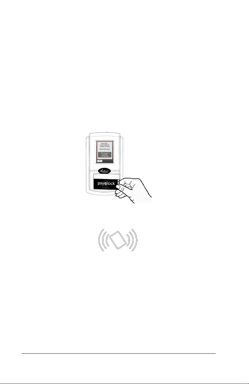
To punch, move the badge over the badge reader symbol below the
illuminated oval target area on the front of the clock.
When the badge is near the clock; a confirmation beep will sound, a
text message will appear, a custom audio message may be played,
and the oval target area will turn either green or red indicating a good
or bad transaction.
The clock will display an error message if you scan a badge that has
not yet been assigned to a specific employee in PayClock.
Notice: The clock utilizes an internal antenna to read the employee
badges. Make sure these badges are stored at least 6” away from
the clock when not in use to avoid accidental badge reads.
Using the PC700 Series Clock • 15
Page 20
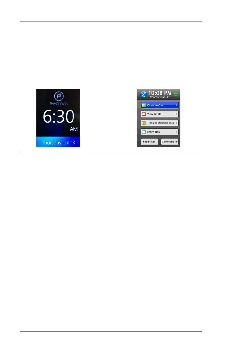
Idle Screen
Home Screen
PC700 Series Clock Idle Screen
The clocks display will change to an idle screen when there is no
activity for 2 minutes. While in idle screen mode the day of the week,
time and date will display in large easy to ready characters. The
clock is fully functional while the screen is idle and the display will
exit idle mode when a badge is presented or the screen is tapped or
when the clock is updated.
Employee Transactions using Badges
Employees can record transactions or view total information by
presenting a badge.
Clocking IN/Out
• Move the badge over the badge reader symbol below the
illuminated oval target area on the front of the clock.
• When the badge is in close to the clock a confirmation beep
will sound, a text message will appear, a custom audio
message may be played, and the oval target area will turn
either green or red indicating a good or bad transaction.
Department Transfers
• Press the Transfer Depts. button on the touch-pad of the
clock.
• Move the badge over the badge reader symbol below the
illuminated oval target area on the front of the clock.
16 • Using the PC700 Series Clock
Page 21

• When the badge is in close to the clock a confirmation beep
will sound, and the list of available departm ents will dis play.
• Press the button for the desired department. A confirmation
screen will display showing the showing the department into
which the employee transferred.
Amount Entries
• Press the Enter Amounts button on the touch-pad of the
clock.
• Move the badge over the badge reader symbol below the
illuminated oval target area on the front of the clock.
• When the badge is in close to the clock a confirmation beep
will sound. The Enter Amt. screen will displa y.
• Using the numeric key pad enter the value for the amount
and press Enter. A confirmation screen will display showing
the showing the amount entered for the employee.
Viewing Totals
• Press the View Totals button on the touch-pad of the clock.
• Move the badge over the badge reader symbol below the
illuminated oval target area on the front of the clock.
• When the badge is in close to the clock, a confirmation beep
will sound, and the employee’s grand totals for the pay
period and any benefit time will display.
Employee Transactions using a PIN
Employees can record transactions or view total information by using
the touch-panel on the clock.
Clocking IN/Out
• Press the Clock In/Out button on the touch-pad of the clock.
• The Enter PIN screen will display. Using the numeric key
pad enter the employee’s PIN number and press Enter.
Using the PC700 Series Clock • 17
Page 22

• A confirmation beep will sound, a text message will appear,
a custom audio message may be played, and the oval target
area will turn either green or red indicating a good or bad
transaction.
Department Transfers
• Press the Transfer Depts. button on the touch-pad of the
clock.
• The Enter PIN screen w i ll d is p lay. Using the numeric key
pad enter the employee’s PIN number and press Enter.
• A confirmation beep will sound and the list of available
departments will displa y.
• Press the button for the desired department. A confirmation
screen will display showing the showing the department into
which the employee transferred.
Amount Entries
• Press the Enter Amounts button on the touch-pad of the
clock.
• The Enter PIN screen will display. Using the numeric key
pad enter the employee’s PIN number and press Enter.
• A confirmation beep will sound. The Enter Amt. screen will
display.
• Using the numeric key pad enter the value for the amount
and press Enter.
• A confirmation screen will display showing the showing the
amount entered for the employee.
Viewing Totals
• Press the View Totals button on the touch-pad of the clock.
• The Enter PIN screen will display. Using the numeric key
pad enter the employee’s PIN number and press Enter.
• A confirmation beep will sound and the employee’s grand
totals for the pay period and any benefit time will display.
18 • Using the PC700 Series Clock
Page 23

Supervisor Transactions
Supervisors have the ability at the clock to view and edit employee
punches, add new employees, send messages and override shift
lockouts. To set up an employee as a supervisor, in PayClock Online
set the desired employees Access Profile to “Supervisor”.
Note: Some supervisor functions require that the clock have an
active connection to the internet.
To enter supervisor mode at the clock, press the Supervisor button.
The Enter PIN screen will display.
• Using the numeric key pad enter the supervisors PIN
number and press Enter or move the supervisors badge over
the badge reader symbol below the illuminated oval target
area on the front of the clock.
• The Select an Employee screen will display.
Viewing Punches
At the clock press the Supervisor button. The Enter PIN screen will
display.
• Using the numeric key pad enter the supervisors PIN
number and press Enter or move the supervisors badge over
the badge reader symbol below the illuminated oval target
area on the front of the clock.
• At the Select an Employee screen, press the button of the
desired employee.
• Press View / Edit Punches. The Punches screen will display.
• Use the left, right, up or down arrows to scroll through the
punch information.
• When finished press the
screen.
button to return to the default
Adding Punches
This supervisor function requires that the clock have an active
connection to the internet.
At the clock press the Supervisor button. The Enter PIN screen will
display.
Using the PC700 Series Clock • 19
Page 24

• Using the numeric key pad enter the supervisors PIN
number and press Enter or move the supervisors badge over
the badge reader symbol below the illuminated oval target
area on the front of the clock.
• At the Select an Employee screen, press the button of the
desired employee.
• Press View / Edit Punches. The Punches screen will display.
• Use the left or right arrows to select the desired date and
press the +Punch button.
• Using the up and down arrows set the desired hour and
minute and then click OK.
• At the confirmation screen select Yes to add the pu nch. The
added punch will display on the screen and will be added to
the timecard.
• When finished press the
screen.
button to return to the default
Viewing Totals
At the clock press the Supervisor button. The Enter PIN screen will
display.
• Using the numeric key pad enter the supervisors PIN
number and press Enter or move the supervisors badge over
the badge reader symbol below the illuminated oval target
area on the front of the clock.
• At the Select an Employee screen press, the button of the
desired employee.
• Press View Totals, the employee’s grand totals for the pay
period and any benefit time will display.
• When finished press the
screen.
button to return to the default
Send Message
At the clock press the Supervisor button. The Enter PIN screen will
display.
20 • Using the PC700 Series Clock
Page 25

• Using the numeric key pad enter the supervisors PIN
number and press Enter or move the supervisors badge over
the badge reader symbol below the illuminated oval target
area on the front of the clock.
• At the Select an Employee screen, press the button of the
desired employee.
• Press Send Message. Select to send a sound message or a
text message.
• Using the up and down arrows select the desired sound or
text message.
• At the confirmation screen select Yes and OK. On the next
punch, the employee will receive the sound or text message.
• When finished press the
screen.
button to return to the default
Override Lockout
At the clock press the Supervisor button. The Enter PIN screen will
display.
• Using the numeric key pad enter the supervisors PIN
number and press Enter or move the supervisors badge over
the badge reader symbol below the illuminated oval target
area on the front of the clock.
• At the Select an Employee screen, press the button of the
desired employee.
• Press Override Lockout.
• At the confirmation screen select Yes to have the next punch
for the employee ignore the shift lockout.
• When finished press the
screen.
button to return to the default
Settings - Set/Change PIN
This supervisor function requires that the clock have an active
connection to the internet.
At the clock press the Supervisor button. The Enter PIN screen will
display.
Using the PC700 Series Clock • 21
Page 26

• Using the numeric key pad enter the supervisors PIN
number and press Enter or move the supervisors badge over
the badge reader symbol below the illuminated oval target
area on the front of the clock.
• At the Select an Employee screen, press the button of the
desired employee.
• Press Settings. The Change Settings screen will display.
• Press the Set/Change PIN button. The PIN Settings screen
will display.
Change PIN
• Press the Change PIN button and using the numeric key pad
enter the new PIN for the selected employee and press
Enter.
• At the confirmation screen select Yes to change the PIN.
• When finished press the
screen.
button to return to the default
Delete PIN
• Press the Delete PIN button.
• At the confirmation screen select Yes to delete the PIN.
• When finished press the
screen.
button to return to the default
Disable PIN Entry
• Press the Disable PIN Entry option.
• You know PIN entry is disabled when there is a check in
the box.
• When finished press the
screen.
button to return to the default
Settings - View/Assign Badge
This supervisor function requires that the clock have an active
connection to the internet.
22 • Using the PC700 Series Clock
Page 27

At the clock press the Supervisor button. The Enter PIN screen will
display.
• Using the numeric key pad enter the supervisors PIN
number and press Enter or move the supervisors badge over
the badge reader symbol below the illuminated oval target
area on the front of the clock.
• At the Select an Employee screen, press the button of the
desired employee.
• Press Settings. The Change Settings screen will display.
• Press the View/Assign Badge button. The Badge Settings
screen will display.
Change Badge
• Press the Change Badge b utton . Present the badge when
prompted.
• At the confirmation screen select Yes to change the Badge.
• When finished press the
screen.
button to return to the default
Disable Badge Entry
• Press the Disable Badge Entry option.
• You know Badge entry is disabled when there is a check
in the box.
• When finished press the
screen.
button to return to the default
Administrator Functions
The clock has one administrator. The administrator function allows
you to review the device information, set up the network
communications, set the time / date, review an error log and reset
the clock to the factory defaults.
To enter administrator mode at the clock, press the Admin button.
The Enter PIN screen will display.
• Using the numeric key pad enter the administrator PIN
number and press Enter.
Using the PC700 Series Clock • 23
Page 28

• The Administrator Main Menu screen will display.
Sync Now
This menu item allows you to force an update from PayClock Online.
To enter administrator mode at the clock, press the Admin button.
The Enter PIN screen will display.
• Using the numeric key pad enter the administrator PIN
number and press Enter.
• The Administrator Main Menu screen will display.
• Press Sync Now, the clock will download the latest changes
from PayClock Online.
Device Information
This menu item displays information and allows you to check for
updates to the firmware. To check for updates:
To enter administrator mode at the clock, press the Admin button.
The Enter PIN screen will display.
• Using the numeric key pad enter the administrator PIN
number and press Enter.
• The Administrator Main Menu screen will display.
• Press Device Information. The Device Information screen
will display.
• Press the Check for Updates button. Please be patient this
may take a few minutes.
• When finished press the center of the screen and then press
the back button until you have returned to the default
screen.
Network Setup - Clock Settings
This menu allows you to manually configure the network
communication settings between the clock and PayClock Online.
To enter administrator mode, at the clock press the Admin button.
The Enter PIN screen will display.
• Using the numeric key pad enter the administrator PIN
number and press Enter.
24 • Using the PC700 Series Clock
Page 29

• The Administrator Main Menu screen will display.
• Press Network Setup. The Network Setup screen will
display.
• If you want to set the clock’s IP address as a “Static” IP turn
off DHCP by pressing the OFF button. The screen will
refresh and more buttons will become active.
• Press the IP Address button. The IP Address screen will
display.
• Using the numeric key pad enter the IP address you want to
assign to the clock and press OK.
• Press the Subnet Mask button. The Subnet Mas k screen will
display.
• Using the numeric key pad enter the address you want to
assign to the clock and press OK.
• Press the Gateway button. The Default Gateway screen will
display.
• Using the numeric key pad enter the address you want to
assign to the clock and press OK.
• When finished press the back button unti l you have
returned to the default screen.
Network Setup - WiFi
This option is used to select and connect to a WiFi access point.
• From the PC700 touchpad press the Admin button. Enter the
administrator password and press Enter.
• The Administrator Main Menu screen will display.
• Press Network Setup. The Network Setup screen will
display.
• Press WiFi. The PC700 will check to see if there are any Wi-
Fi connections within range and display them in a list. Note:
Make sure the WiFi Enabled is set to Yes.
• Select the desired Wi-Fi connection from the list.
• The Enter Passcode screen will display with a keypad.
• Using the master buttons to select upper case letters, lower
case letters, numbers or symbols enter the passcode for the
Using the PC700 Series Clock • 25
Page 30

wireless network. Note: You may need to contact your
network administrator for the wireless passcode information.
• Press OK. A confirmation m essage will disp lay when the
PC700 is connected, press OK.
• When finished press the back button unti l you have
returned to the home screen.
Date/Time Setup - Date
This menu allows you to manually configure the time zone, DST and
how the hours will display on the clock.
Date/Time Setup - Time Zone
This menu allows you to manually configure the time zone on the
clock.
To enter administrator mode at the clock, press the Admin button.
The Enter PIN screen wi ll display.
• Using the numeric key pad enter the administrator PIN
number and press Enter.
• The Administrator Main Menu screen will display.
• Press Date/Time Setup. The Date Setup screen will display.
• Press the Time Zone button. The Choose Time Zone screen
will display.
• Using the up and down arrow keys select the desired time
zone and click OK.
• When finished press the back button unti l you have
returned to the default screen.
Date/Time Setup - Daylight Saving Time
This menu allows you to manually configure the DST on the clock.
To enter administrator mode at the clock, press the Admin button.
The Enter PIN screen will display.
• Using the numeric key pad enter the administrator PIN
number and press Enter.
• The Administrator Main Menu screen will display.
• Press Date/Time Setup. The Date Setup screen will display.
26 • Using the PC700 Series Clock
Page 31

• Under Daylight Save Time press either the On or Off.
• The screen will refresh with the newly selected option.
• When finished press the back button unti l you have
returned to the default screen.
Date/Time Setup - Time Display Format
This menu allows you to manually configure how the hours will
display on the clock.
To enter administrator mode at the clock press the Admin button.
The Enter PIN screen will display.
• Using the numeric key pad enter the administrator PIN
number and press Enter.
• The Administrator Main Menu screen will display.
• Press Date/Time Setup. The Date Setup screen will display.
• Under Time Display Format press either the 12HR or 24HR.
• The screen will refresh with the newly selected option.
• When finished press the back button unti l you have
returned to the default screen.
Error Log
This menu item displays any errors that the clock may have
experienced.
To enter administrator mode at the clock press the Admin button.
The Enter PIN scree n will display.
• Using the numeric key pad enter the administrator PIN
number and press Enter.
• The Administrator Main Menu screen will display.
• Press Error Log. The Event Log Details screen will display.
• Use the left or right arrow keys to scroll through any errors.
• When finished press the center of the screen and then press
the back button until you have returned to the default
screen.
Using the PC700 Series Clock • 27
Page 32

Relay Settings
This menu allows you to configure how the clock uses the on-board
relay.
To enter administrator mode at the clock press the Admin button.
The Enter PIN screen will display.
• Using the numeric key pad enter the administrator PIN
number and press Enter.
• The Administrator Main Menu screen will display.
• Press Relay Settings. The Relay Setup screen will display.
• Select the Mode.
o Off - The relay is disabled.
o Access - The relay will be used to activate a door strike
allowing employees to enter the facility.
o Signal - The relay will open/close to sound the signaling
device.
• The Schedule button will displa y if Signal is selected. Press
Schedule and enter the bell events. Up to 100 events can be
programmed.
• Select the duration to for the relay. By default, it is set at 5
seconds.
• Use the Test button to activate the on-board relay to test the
connection.
• When finished press the back butto n unti l you have
returned to the default screen.
See Appendix D for steps to add/edit/delete bell events.
Test Connection
This menu allows you to test the clocks connection to the internet
and PayClock Online.
To enter into administrator mode at the clock press the Admin
button. The Enter PIN screen will display.
• Using the numeric key pad enter the administrator PIN
number and press Enter.
• The Administrator Main Menu screen will display.
28 • Using the PC700 Series Clock
Page 33

• Press Test Connection.
• The internet connection, ports and connection to PayClock
Online will be tested.
• When finished press the back button unti l you have
returned to the default screen.
See Appendix A for details on testing the connection.
Reset
Use caution when selecting this menu item. This menu item will reset
the entire clock to the manufacturer default settings.
All settings, administrators, supervisors, employees and data
will be cleared; you cannot recover this information.
To enter administrator mode at the clock press the Admin button.
The Enter PIN screen will display.
• Using the numeric key pad enter the administrator PIN
number and press Enter.
• The Administrator Main Menu screen will display.
• Press Reset. The Clock Reset screen will display.
• Press the Reset Clock button.
• At the confirmation screen press Yes if you are sure you
wish to reset and clear the clock.
• The clock will reboot and restart as if it were a new clock that
had never been used.
WARNING: Use caution when selecting this menu item. This
menu item will reset the entire clock to the manufacturer default
settings. All settings, administrators, supervisors, employees and
data will be cleared; you cannot recover this inf or mation.
Using the PC700 Series Clock • 29
Page 34

Issue
Resolution
Troubleshooting the PC700 Series Clock
If the clock doesn’t communicate with the PayClock Online, try these
suggestions:
General Troubleshooting
• Make sure that all connections are secure and the cable is
intact or the wireless access point is connected.
• Make sure that the network cable is securely connected to
the Ethernet port on the clock.
• Make sure the wireless access point is working.
PC700 Series Troubleshooting
If after going through each item above you are the clock is still not
communicating with PayClock Online, have the network
administrator or IT person make sure there aren’t any issues with the
network.
The terminal isn’t connecting to
PayClock Online.
30 • Troubleshooting the PC700 Series Clock
• Make sure that the clock’s power supply is securely
connected to an electrical outle t.
• Make sure that the power supply is securely connected to
the clock and the unit is powered up.
If your terminal isn’t connecting
to PayClock Online, use the Test
Connection button. See
Appendix A for details.
Page 35
The clock shows “Not Found”
when a badge is presented.
Make sure that the number that
is printed on the badge matches
what was entered in the Badge
Number field in PayClock for the
employee.
A blinking light shows in the
small rectangular opening to the
left of the illuminated oval on the
front of the clock. What does it
mean?
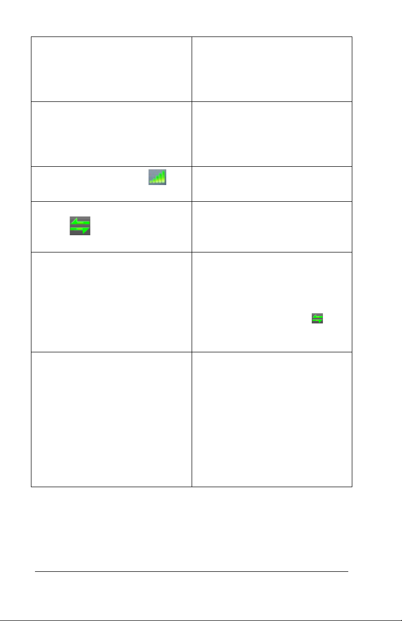
What are the green bars on
the display representing?
What are the double green
arrows
on the display
representing?
Why does the clock show “Punch
Accepted” instead of Punch In or
Out when an employee
punches?
How do I disable the idle screen
on the clock?
This blinking light represents the
wired connection to the network
(LAN). If the light is not blinking
there isn’t a connection to the
network (LAN).
This represents the WiFi signal
strength.
This represents that the clock is
connected to the internet and
PayClock Online.
The clock lost the connection to
the internet, so it displa ys Punch
Accepted. The clock must have a
connection to the internet to
determine if a punch is In or Out.
Check to see if the arrow
icon
is displaying at the top of the
screen.
While the idle screen doesn’t
affect the operation of the clock
some users may wish to disable
the feature. To disable the idle
screen, press the Admin button
and enter 528436 then press
Enter. Press OK to the
confirmation message “Idle
Screen Mode: Off”. Note: to
reactivate the idle screen simply
enter the 528436 code again.
Troubleshooting the PC700 Series Clock • 31
Page 36

Appendix A – Testing the Connection to PayClock Online
Important
This tool has been designed to assist you in the event the clock fails to
connect to PayClock Online. Even with this tool it may be necessary to
involve your IT department or someone familiar with your network if you
have connection issues.
The PC700 series clock has a function that will allow the user to test the
connection to PayClock Online. This test will verify the internet
connection, access to the internet through the required ports and the
connection to the PayClock Online service.
With the clock powered up and connected to the network, tap the Admin
button and enter the administrator PIN.
• The Administrator Menu screen will display.
• Tap Test Connection.
Test 1 - Internet connection test.
Pass = The test cycle will move to the port test.
Fail – What should I do if this test fails?
• Does another device successfully connect to the internet?
Such as a laptop(wired/wifi) or a smartphone(wifi).
• Does the clock show an IP address?
• Go to Admin>Network Setup
• If no IP Address shows contact your IT department for
assistance.
32 • Appendix A – Testing the Connection to PayClock Online
Page 37

Test 2 – Ports used by the clock will tested.
Pass = The test cycle will move to the PayClock Online service
test.
Fail – What should I do if this test fails?
• Open the listed port(s) to traffic.
• Contact your IT department to open the listed port(s) to traffic.
Test 3 – PayClock Online Service used by the clock will tested.
Pass = The test cycle will display a summary of the test.
Fail – What should I do if this test fails?
• Open the listed port(s) to Inbound / Outbound traffic.
• Contact your IT department to open the listed port(s) to traffic.
Notes
The internet test will attempt to ping www.google.com
. If ping is disabled
on the network a false test result could be displayed and may require you
to involve your IT department or someone familiar with your network.
It may be necessary to involve your IT department or someone familiar
with your network if there is a failure with the Ports or PayClock Online
Services test which requires changes to the network / firewall settings.
Appendix A – Testing the Connection to PayClock Online • 33
Page 38
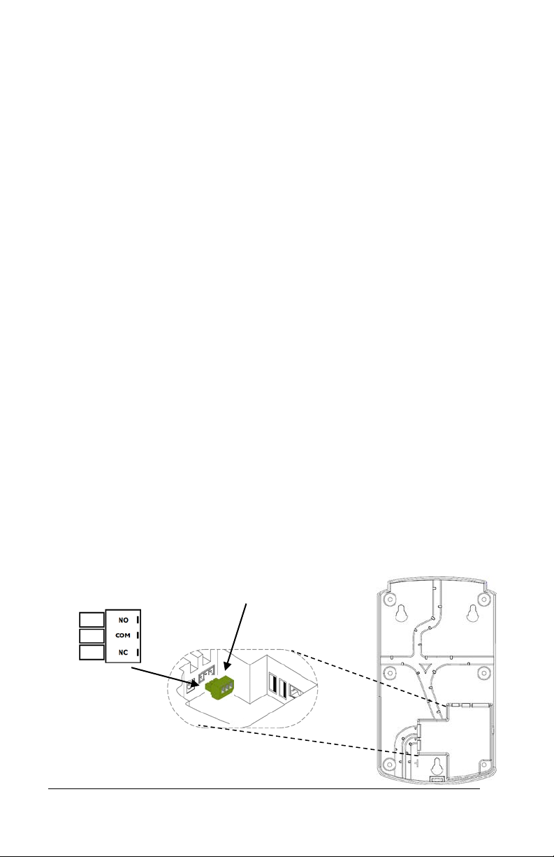
Appendix B - Bell Relay Connections
The PC700 has a built-in relay that can control bells or door access.
Relay Specifications
• Type: Dry Contact Closure
• Rating: 2 amps at 24VDC or 120VAC
• Contacts: NO-Normally Open, COM Common, NC Normally
Closed
Bell Relay Connections
When you are connecting to a signaling device make sure you have
the following skills:
• Understand basic wiring principles and techniques
• Can interpret wiring diagram s
• Have circuit wiring experien ce
Note: The wiring must be installed in accordance with national and
local electrical codes.
To connect the signaling device
Unplug the relay screw clock connector.
34 • Appendix B - Bell Relay Connections
Page 39
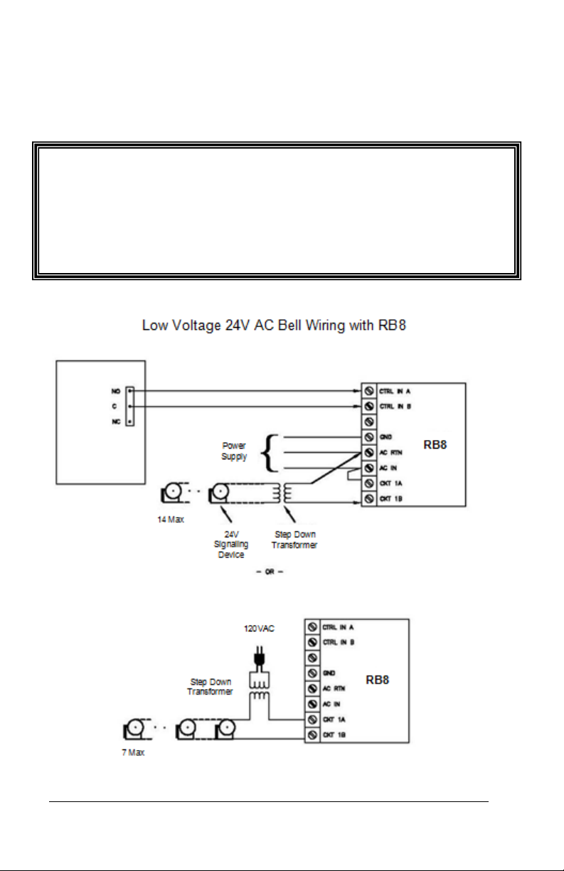
Important! Relay contacts provide no power for signaling devices. The
PC700
Connect the wires from the signaling device to the screw clocks.
Plug the clock connector into the socket on the PC700. Only one (1)
wire should be inserted into the clock block positions NO and COM,
all wire splices should be done externally. See the following
diagrams for details.
relay is a dry contact closure rated 2 amps at 24VDC or 120 VAC.
Connecting a device or series of devices that draw more than the rated
amperage from the clock will result in serious damage! It is
recommended to use the optional RB8 Relay Booster Box to control
devices that require more than 2 amps.
Appendix B - Bell Relay Connections • 35
Page 40
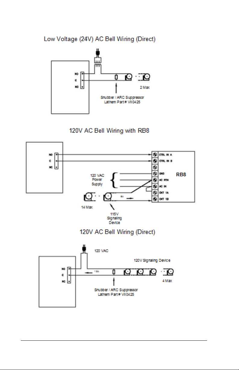
PC700
PC700
PC700
36 • Appendix B - Bell Relay Connections
Page 41
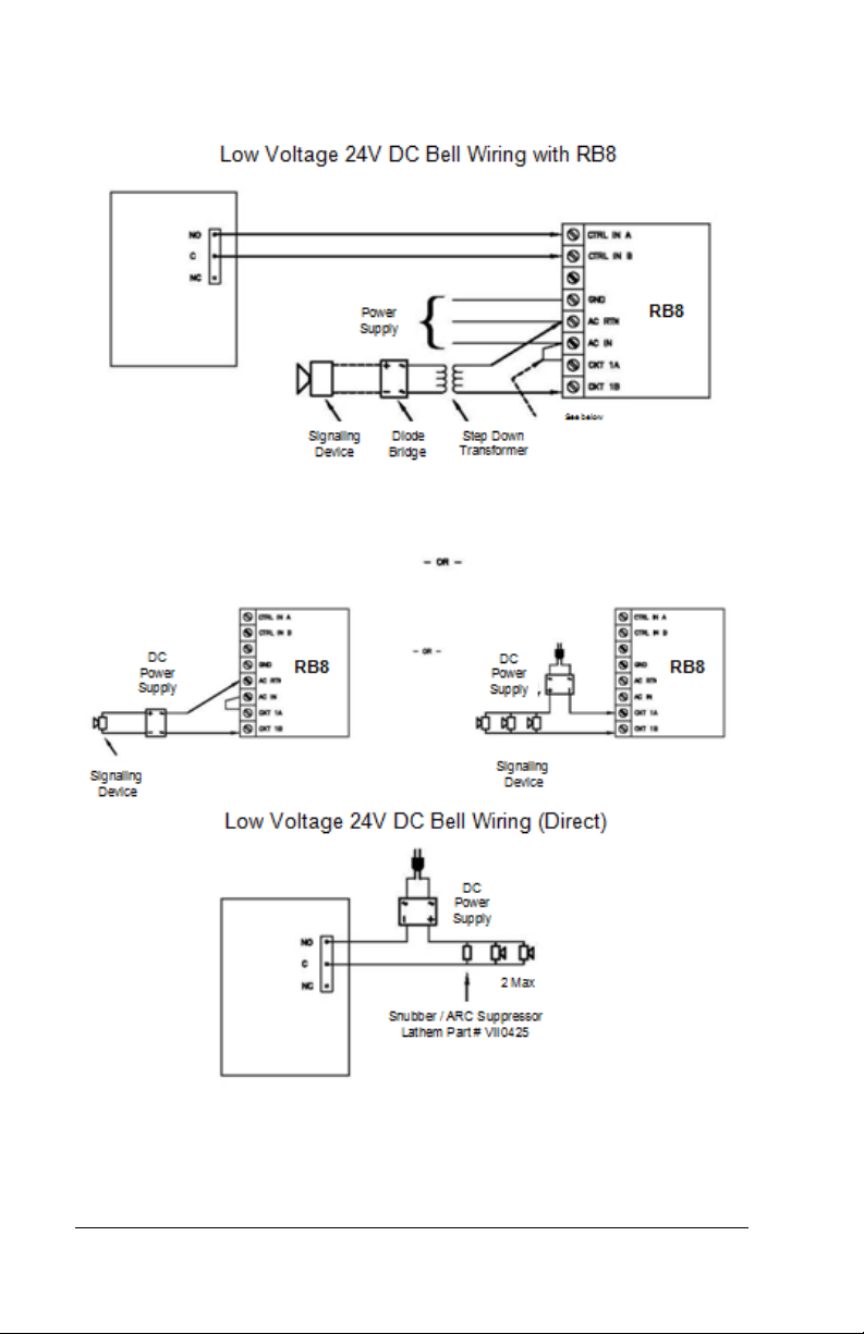
PC700
PC700
Appendix B - Bell Relay Connections • 37
Page 42
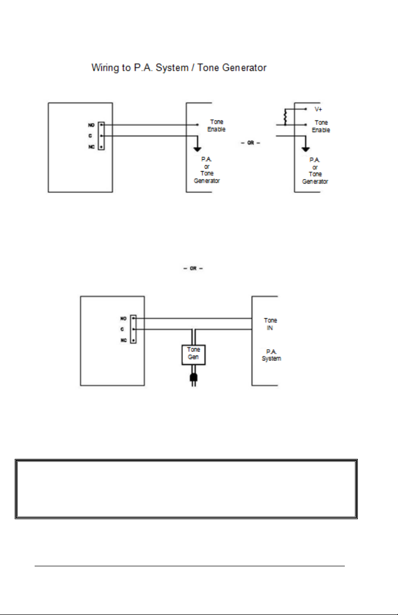
Important! Connecting the PC700 to a public address (PA) system
PC700
PC700
requires the use of an external Tone G enera tor . Contact your PA
supplier to acquire an appropriate Tone Generator for your system.
38 • Appendix B - Bell Relay Connections
Page 43
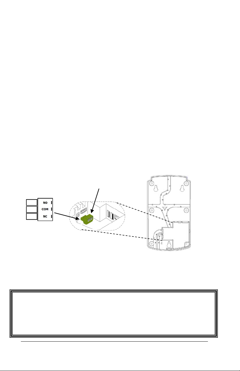
Important! Relay contacts provide no power. The relay is a dry contact
Appendix C - Access Relay Connections
When you are connecting to a door access device make sure you
have the following skills:
• Understand basic wiring principles and techniques
• Can interpret wiring diagram s
• Have circuit wiring experien ce
Note: The wiring must be installed in accordance with national and
local electrical codes.
Connecting the PC700 to a Door Strike
Unplug the relay screw clock connector.
Connect the wires from the door access device to the screw clocks.
Plug the clock connector into the socket on the PC700. Only one (1)
wire should be inserted into the clock block positions NO and COM,
all wire splices should be done externally. See the following
diagrams for details.
closure rated 2 amps at 24VDC or 120 VAC. Connecting a door strike
that draws more than the rated amperage from the clock will result in
serious damage! It is recommended to use the optional RB8 Relay
Booster Box for a door strike that requires more than 2 amps.
Appendix C - Access Relay Connections • 39
Page 44
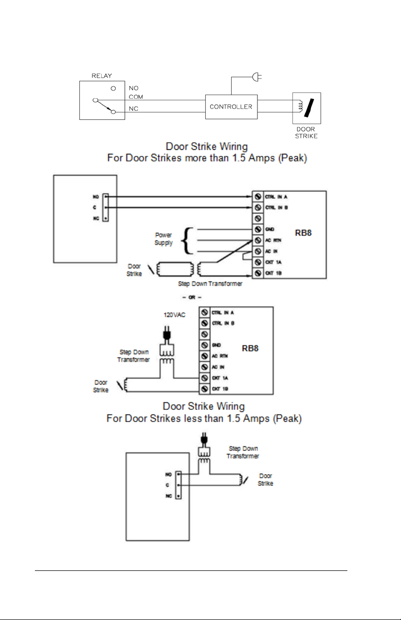
Wiring for Door Access Control System
PC700
PC700
40 • Appendix C - Access Relay Connections
Page 45

Appendix D Add/Edit/Delete Bell
Events
Up to 100 events can be programmed. Events consist of the time
and the day of week the event will activate the relay.
Adding a Bell Event
• From the PC700 touchpad press the Admin button. Enter the
administrator PIN and press Enter.
• From the Administrator Main Menu press Relay Settings.
• The Relay Settings screen will display.
• Press Signal under the Mode Settings. The button will
change to blue identifying it’s enabled.
• Press Schedule under Signal Events. The Signal Event
Schedule screen will display.
• Press +Event. The Edit Event screen will display.
• Using the up and down arrow keys select the desired hour,
minute and AM/PM for the bell event.
• Press the buttons for the desired days of the week, a check
will display in the box identifying the da y is selected.
• Press OK to save the event. The programmed event will
display in the list.
• Continue adding the desired events.
• When finished press the back button unti l you have
returned to the home screen.
Appendix D - Add/Edit/Delete Bell Events • 41
Page 46

Editing a Bell Event
• From the PC700 touchpad press the Admin button. Enter the
administrator PIN and press Enter.
• From the Administrator Main Menu press Relay Settings.
• The Relay Settings screen will display.
• Press Schedule under Signal Events. The Signal Event
Schedule screen will display with all the schedule events.
• Select the desired Event. The Edit Event screen will display.
• Make the needed changes for the event.
• Press OK to save the changes. The edited programmed
event will display in the list.
• When finished press the back button unti l you have
returned to the home screen.
Deleting a Bell Event
• From the PC700 touchpad press the Admin button. Enter the
administrator PIN and press Enter.
• From the Administrator Main Menu press Relay Settings.
• The Relay Settings screen will display.
• Press Schedule under Signal Events. The Signal Event
Schedule screen will display with all the schedule events.
• Select the desired Event. The Edit Event screen will display.
• Press the Delete Event button. Press Yes at the confirmation
message.
• The programmed event will be removed from the list.
• When finished press the back button unti l you have
returned to the home screen.
42 • Appendix D - Add/Edit/Delete Bell Events
Page 47

Glossary of Terms
Administrator
The PC700 series clock has one administrator, the administrator
function allows you review the device information, set up the network
communications, set the time / date, review an error log and reset
the clock to the factory defaults.
Supervisor
An employee configured as a supervisor will have the ability at the
clock to view and edit employee punches, add new employees, send
messages and override shift lockouts.
Glossary of Terms • 43
Page 48

Page 49

Index
A
Add the terminal from
PayClock 8
Administrator Functions 23
I
Install the PC700 Series
Terminal 5
P
Package Contents 4
PC700 Series Terminal Idle
Screen 16
S
Supervisor Transactions 19
Sync Now 24
C
Changing settings from
PayClock Online 11
E
Employee transactions using
a PIN 17
Employee transactions using
badges 16
F
Features & Specifications 2
G
Getting Help 2
T
Troubleshooting 30
U
Using the PC700 Series
Terminal 15
W
Wi-Fi Connection 6
PC600 User's Guide Index • 45
Page 50

One-Year Limited Warranty
Lathem warrants the hardware products described in this guide against
defects in material and workmanship for a period of one year from date of
original purchase from Lathem or from an authorized Lathem reseller. The
conditions of this warranty and the extent of the responsibility of Lathem
Time Corporation (“Lathem”) under this warranty are listed below.
1. This warranty will become void when service performed by anyone
other than an approved Lathem warranty service dealer results in
damage to the product.
2. This warranty does not apply to any product which has been subject to
abuse, neglect, or accident, or which has had the serial number altered
or removed, or which has been connected, installed, adjusted, or
repaired other than in accordance with instructions furnished by Lathem.
3. This warranty does not cover dealer labor cost for removing and
reinstalling the machine for repair, or any expendable parts that are
readily replaced due to normal use.
4. The sole responsibility of Lathem under this warranty shall be limited to
repair of this product, or replacement thereof, at the sole discretion of
Lathem.
5. If it becomes necessary to send the product or any defective part to
Lathem or any authorized service dealer, the product must be shipped
in its original carton or equivalent, fully insured with shipping charges
prepaid. Lathem will not assume any responsibility for any loss or
damage incurred in shipping.
6. WARRANTY DISCLAIMER AND LIMITATION OF LIABILITY: Except
only the limited express warranty set forth above, the products are sold
with no expressed or implied warranties of any kind, and the implied
warranties of merchantability and fitness for a particular purpose are
hereby expressly disclaimed. No warranties are given with respect to
products purchased other than from Lathem or an authorized Lathem
reseller and any such products are purchased "as is, with all faults." In
no event will Lathem be liable for any direct, indirect, special, incidental
or consequential damages arising out of or in connection with the
delivery, use or inability to use, or performance of this product. In the
event any limited remedy given herein shall be deemed to have failed of
its essential purpose, Lathem's maximum liability shall be to refund the
purchase price upon return of the product.
7. Proof of date of purchase from Lathem or an authorized Lathem reseller
is required for warranty service on this product.
8. This Warranty grants specific legal rights. Additional legal rights, which
may vary by locale, may also apply.
9. Should any difficulties arise with the performance of this product during
warranty, or with any Lathem authorized service centers, contact
Lathem Time.
Page 51

Page 52

 Loading...