

Page 1

TECHNICAL INSTRUCTIONS
DAYTONA
1-POWER
ENGLISH
383033GB Pag. 1 November 2003
Page 2

TABLE OF CONTENTS
INTRODUCTION…………………………….………………………………………………………………. Pag. 6
- INTRODUCTION AND GENERAL INSTRUCTIOS
- INSTRUCTIONS FOR INSTALLATION
- SPECIAL INSTRUCTIONS FOR USE AND MAINTENANCE
GENERAL CHARACTERISTICS………………………………….……………………………………….Pag. 7
DAYONA 1-POWER MACHINE KEYPAD……………………………………………………………..…. Pag. 7
MACHINE FUNCTION MESSAGES………………………………………………………….…………... Pag. 8
MESSAGE OF MACHINE DOOR POSITIONING
1) MESSAGE OF GROUNDS BIN OUT OF POSITION
2) MESSAGE OF FULL GROUNDS BIN
3) MESSAGE OF COFFEE BOILER HEATING TEMPERATURE NOT REACHED
4) MESSAGE OF STEAM BOILER HEATING TEMPERATURE NOT REACHED
5) MESSAGE OF MANUAL GROUP CLEANING
6) MESSAGE OF MILKER CLEANING
STARTING UP PROCEDURE ………………………………………………………………………….… Pag. 9
MILK BOX HOLDER ASSEMBLY…………………………………………………………………………. Pag. 11
MACHINE DISPENSING…………………………………………………………………………………. Pag. 12
1) STANDARD MACHINE
2) MACHINE WITH WAITERS’ CARD
3) SELF MACHINE
4) SELF MACHINE WITH CREDIT CARD
5) SELF MACHINE WITH COIN MECHANISM
6) SELF MACHINE WITH CREDIT CARD + COIN MECHANISM
DISPENSING BY MEANS OF DECAFFEINATED COFFEE DOOR………………………………….. Pag. 16
CONTINUOUS DISPENSING………..……………………………………………………………………. Pag. 16
STEAM DISPENSING…………………………………………………………………………………… Pag. 16
HOT WATER DISPENSING…..…………………………………………………………………………… Pag. 17
SMART CARD FUNCTIONS………………………………………………………………………….. Pag. 17
1) WAITERS’ SMART CARD
2) OWNER’S SMART CARD
3) TECHNICIAN’S SMART CARD
4) SMART CREDIT CARD
5) READING-WRITING SMART CARD
AUTOMATIC WASHING CYCLE PROCEDURE……………………………………………………… Pag. 19
1) COFFEE GROUP AUTOMATIC TIMED WASHING
2) GROUP-MILKER AUTOMATIC WASHING WITH DETERGENT
2.1) GROUP WASHING
2.2) MILKER WASHING
DOSE PROGRAMMING PROCEDURE……………………………………………………………… Pag. 23
1) BEVERAGE NAME PROGRAMMING
1.1) DECAFFEINATED DOOR FUNCTION
1.2) MOTOR PUMP FUNCTION DURING FILTER COFFEE CYCLE OR LATTE MACCHIATO
1.3) GRIND TIME PROGRAMMING
1.4) PRE-INFUSION TIME PROGRAMMING
1.5) PRE-INFUSION TIME PROGRAMMING FOR FILTER COFFEE CYCLE
1.6) PAUSE PROGRAMMING DURING FILTER COFFEE CYCLE
1.7) COFFEE WATER DOSE PROGRAMMING
1.8) WATER DOSE PROGRAMMING FOR EXTRA WATER VOLUME
1.9) PROGRAMMING OF STEAMED MILK DISPENSING TIME BEFORE COFFEE
1.10 PROGRAMMING THE PAUSE TIME BETWEEN THE PRE STEAMED MILK AND PRE FOAMED MILK
DELIVERY.
1.11) PROGRAMMING OF FOAMED MILK DISPENSING TIME BEFORE COFFEE
1.12) PROGRAMMING OF PAUSE TIME BETWEEN MILK AND COFFEE DISPENSING
1.13) PROGRAMMING OF STEAMED MILK DISPENSING TIME AFTER COFFEE
1.14) PROGRAMMING THE PAUSE TIME BETWEEN THE POST STEAMED MILK AND POST FOAMED MILK
DELIVERY.
1.15) PROGRAMMING OF FOAMED MILK DISPENSING TIME AFTER COFFEE
1.16) PRICE PROGRAMMING OF A SET UP DOSE
1.17) CONTROL OF DELIVERIES OF PROGRAMMED DOSES
1.18) PROGRAMMING MENU FUNCTION FOR TWO CUPS
2) PROGRAMMING OF HOT WATER DOSE FOR TEA
2.1) PROGRAMMING HOT WATER DOSE FOR TEA
383033GB Pag. 2 November 2003
Page 3

2.2) PRICE PROGRAMMING OF A SET UP DOSE
3) STEAM DISPENSING PROGRAMMING
3.1) STEAM DISPENSING TIME PROGRAMMING
3.2) PRICE PROGRAMMING OF A SET UP DOSE
SYSTEM TEMPERATURE INFORMATION PROCEDURE.…………………………………………...Pag. 28
INFORMATION PROCEDURE AND DISPENSING RESET…………………………………………... Pag. 28
1) READ DOSE COUNTER
2) WAITER DOSE RESET
SMART CARD CREDIT CHARGE PROCEDURE ………..…………………………………………… Pag. 30
SYSTEM PROGRAMMING…………………………………………………………………………………Pag. 33
1) MACHINE PARAMETERS
1.1) LANGUAGE SELECTION PROGRAMMING
1.2) MACHINE TYPE CONFIGURATION PROGRAMMING
1.3) SERIAL DOOR FUNCTION
1.4) COFFEE GROUNDS NUMBER PROGRAMMING
1.5) AUTOMATIC CLEANING FUNCTION
1.5.a) WATER DOSE PROGRAMMING FOR AUTOMATIC CLEANING
1.5.b) START TIME PROGRAMMING OF AUTOMATIC CLEANING AFTER THE LAST COFFEE
1.5.c) TIME PROGRAMMING BETWEEN ONE CLEANING CYCLE AND THE NEXT
1.6) PROGRAMMING RINSE AFTER MILK DOSE.
1.6a) PROGRAMMING RINSE AFTER MILK DOSE.
1.7) AUTOMATIC RINSE MILKER MACHINE IN STAND-BY.
1.7a) START TIME PROGRAMMING OF AUTOMATIC MILKER RINSE AFTER THE LAST DOSE MILK BASED.
1.7b) TIME PROGRAMMING BETWEEN ONE MILKER RINSE CYCLE AND THE NEXT.
1.8) M1 TOOLS WORKING TIME PROGRAMMING FOR MAINTENANCE
1.9) WATER FILTER LITRE PROGRAMMING
1.10) GROUP CYCLE NUMBER PROGRAMMING FOR MAINTENANCE
1.11) GROUP CYCLE NUMBER PROGRAMMING FOR MANUAL GROUP CLEANING MESSAGE
1.12) PROGRAMMING BLOCKED DELIVERIES MESSAGE OF GROUP CLEANING
1.13) DOSE NUMBER PROGRAMMING FOR MILKER CLEANING MESSAGE
1.14) PROGRAMMING OF TIME OUT MESSAGE OF MILKER CLEANING
1.15) PROGRAMMING BLOCKED DELIVERIES MESSAGE OF MILKER CLEANING
1.16) COFFEE TEMPERATURE UNIT PROGRAMMING
1.17) CURRENCY DECIMAL NUMBER PROGRAMMING
1.18) MINIMUM CURRENCY UNIT PROGRAMMING
1.19) MAXIMUM CREDIT PROGRAMMING OF THE CREDIT CARD
1.20) COFFEE BOILER TEMPERATURE PROGRAMMING
1.21) STEAM BOILER TEMPERATURE PROGRAMMING
1.22) PROGRAMMING OF STEAM BOILER HEATING TIME AT EACH WATER FILLING UP
1.23) PROGRAMMING THE TIME-OUT BETWEEN ONE MILK-BASED DELIVERY AND THE NEXT.
1.24) PROGRAMMING TIME ADDITIONAL DOSE
1.25) PROGRAMMING OF TEMPERATURE DRAIN STOP OF STEAM BOILER
1.26) SEQUENTIAL HEATING FUNCTION OF COFFEE AND STEAM BOILERS
1.27) PROGRAMMING BUTTON N°16 FUNCTION
1.28) PROGRAMMING TEMPERATURE PROBE TYPE
1.29) PROGRAMMING MAXIMUM HIGER MOTOR IMPULSES
1.30) PROGRAMMING HIGER MOTOR STAND-BY POSITION IMPULSES
1.31) PROGRAMMING HIGER MOTOR DELIVERY POSITION IMPULSES
1.32) PROGRAMMING MAXIMUM LOWER IMPULSES
1.33) PROGRAMMING LOWER MOTOR STAND-BY POSITION IMPULSES
1.34) PROGRAMMING LOWER MOTOR EXPELLING POSITION IMPULSES
2) GROUP CLEANING PROGRAMMING
2.1) WATER DOSE PROGRAMMING FOR AUTOMATIC CLEANING WITH DETERGENT
2.2) PAUSE TIME PROGRAMMING DURING AUTOMATIC CLEANING WITH DETERGENT
2.3) PROGRAMMING OF CYCLE NUMBER
3) MILKER CLEANING PROGRAMMING
3.1) MILKER CLEANING TIME PROGRAMMING
4) SET-UP ENCODER
5) GROUP MANUAL MOVEMENTS
6) TEST ACTUATORS
7) SYSTEM DATA RESET INFO
7.1) RESET OF TOTAL DISPENSING NUMBER CARRIED OUT BY SELECTION BUTTONS
7.2) READING RESET OF AUTOMATIC GROUP CLEANING NUMBER WITH DETERGENT
7.3) READING RESET OF MILKER CLEANING NUMBER
7.4) READING RESET OF CYCLE NUMBER CARRIED OUT BY THE COFFEE GROUP
7.5) READING RESET OF M1 TOOLS WORKING TIME
7.6) READING RESET OF WATER LITRE NUMBER REGENERATED BY THE WATER FILTER
383033GB Pag. 3 November 2003
Page 4

7.7) READING RESET OF TOTAL CYCLE NUMBER CARRIED OUT BY THE COFFEE GROUP
8) ALARM DATA MEMORY
9) SMART CARD PROGRAMMING
9.1) DEVICE CODE DISPLAY AND MODIFICATION
9.2) WAITER’S CARD CREATION
9.2) WAITER’S CARD NUMBER ENABLE / DISABLE
9.3) OWNER’S CARD CREATION
9.4) CREDIT CARD CREATION
9.5) CREDIT CHARGE
9.6) TECHNICIAN’S CARD CREATION
10) PARAMETERS PRESET
11) FILES MANAGER
12) UPDATE SOFTWARE
13) HISTORY HIGER MOTOR
14) HISTORY LOWER MOTOR
ALARM MESSAGES – MACHINE SHUTDOWN…………………………………………………………...Pag. 64
1) GROUP MOVEMENT BOARD ALARM
2) TIME OUT IMPULSES, UPPER PISTON MOTOR
3) TIME OUT IMPULSES, LOWER PISTON MOTOR
4) TOO MUCH COFFEE ALARM
5) UPPER MOTOR ERROR ALARM
6) LOWER MOTOR ERROR ALARM
7) STEAM BOILER FILLING ALARM
8) STEAM BOILER MINIMUM LEVEL ALARM
9) VOLUME METER ALARM
10) WATER SOFTENER ALARM
11) TOOLS MAINTENANCE ALARM
12) COFFEE BOILER TEMPERATURE ALARM (TOO HIGH)
13) COFFEE BOILER TEMPERATURE ALARM (TOO LOW)
14) STEAM BOILER TEMPERATURE ALARM (TOO HIGH)
15) STEAM BOILER TEMPERATURE ALARM (TOO LOW)
16) FAULTY DATA ALARM
17) GROUP MAINTENANCE ALARM
18) MACHINE SHUTDOWN ALARM
19) INTERVENTION OF STEAM BOILER SAFETY THERMOSTAT
20) INTERVENTION OF STEAM BOILER SAFETY PROBE
21) MANUAL GROUP CLEANING MESSAGE
22) MILKER CLEANING MESSAGE
23) MILKER CLEANING MESSAGE WITH BLOCKED DELIVERIES
24) GROUP CLEANING MESSAGE WITH BLOCKED DELIVERIES
MACHINE COMPONENTS CALIBRATING……………………………………………………………… Pag. 71
1) CALIBRATING OF COFFEE BOILER EXPANSION VALVE
2) COFFEE DISPENSING PRESSURE CALIBRATING (PUMP PRESSURE)
3) COFFEE GRINDING DEGREE CALIBRATING
4) CALIBRATING OF COFFEE OUTLET FLOW ADJUSTMENT
5) DECANTER FUCNTION TO STOP THE RETURN OF THE MILK FLOW
6) COLD – HOT WATER MIX FLOW ADJUSTMENT FOR TEA.
BODY DISASSEMBLY PROCEDURE……………………………………………….…………………… Pag. 73
BOILER DRAINING PROCEDURE……………………………………………………………………….. Pag. 74
SPECIAL MAINTENANCE…………..…………………………………………………………………….. Pag. 74
CONTROL UNIT LEGEND….……………………………………………………………………………...Pag. 75
TABLE LEGEND …………………………………………………………………………………………….Pag. 76
383033GB Pag. 4 November 2003
Page 5

EU / UE
DICHIARAZIONE DI CONFORMITA’ – KONFORMITÄTSERKLÄRUNG
DECLARATION OF CONFORMITY – DECLARATION DE CONFORMITE
Noi, Wir, We, Nous
La Pavoni S.p.A.- Via Privata Gorizia, 7
20098 San Giuliano Milanese (MI)
dichiariamo sotto nostra responsabilità, che il prodotto
erklären in alleiniger Verantwortung, daß das Produckt
declare under our sole responsibility that the product
déclarons sous notre seule responsabilité que le produit
(Nome, tipo o modello, Nr. lotto, del campione o della serie, eventuali fonti e numero pezzi)
(Bezeichnung Typ oder Modell, Los-, Chargen- oder Seriennummer, möglichst Herkunft und Stückzahl)
(Name, type or model, lot, batch or serial number, possible sources and number of items)
(Nom, type ou modèle, no de lot, d’échantillons ou de série, éventuellement sources et nombre
d’éxemplaires)
DAYTONA 1 – 2 POWER
al quale si riferisce questa dichiarazione, è conforme alla(e) norma(e) o ad altro(i) documento(i) della
normativa
auf das sich diese Erklärung bezieht, mit der/den folgenden Norm(en) oder normativen Dokument(en)
übereinstimmt
to which this declaration relates is in conformity with the following standard(s) or other normative
document(s)
auquel se référre cette déclaration est conforme à la (aux) norme(s) ou autre(s) document(s) normatif(s)
73/23 CE 97/23/CE 89/336 CE
(Intestazione e/o numero e data della pubblicazione della(e) Norma(e) o altro(i) documento(i) della
Normativa)
(Titel und/oder Nummer sowie Ausgabedatum der Norm(en) oder der anderen normativen Dokument(en))
(Title and/or number and date of issue of the standard(s) or other normative document(s))
(Titre et/ou no et date de publications de la (des) norme(s) ou autre(s) document(s) normatif(s))
Conformemente alle disposizioni della(e) Direttiva(e): Gemäss den Bestimmungen der Richtlinie(n):
following the regulations of the Directive(s): conformément aux dispositions de(s) Directive(s):
(se applicabile) (falls zutreffend) (if applicable) (le cas échéant)
89/392 CE
San Giuliano Milanese La Pavoni S.p.A.
15/06/2003 Il Procuratore
Dr. Eugenio Pennè
383033GB Pag. 5 November 2003
Page 6

INTRODUCTION AND GENERAL INSTRUCTIONS
Thoroughly read the instructions contained in this booklet because it gives important information regarding safety for installation, use and maintenance.
Keep this booklet in a safe and accessible place for further consultation.
This machine must be used only for the purpose it was designed:
dispensing coffee, cappuccino and pouring hot water
Any other use is to be considered inappropriate and therefore dangerous.
The manufacturer declines all responsibility for damage caused by any improper, incorrect and unreasonable use of the machine.
The use of any electric appliance implies the observance of some fundamental rules.
More specifically:
- do not touch the appliance with your hands or feet wet or damp
- do not use the appliance with bare feet
- do not pull the power cord to disconnect the plug from the power socket
- do not leave the appliance exposed to the weather (rain, sun, frost)
- do not let children or untrained persons use the appliance.
Before carrying out any cleaning and maintenance, disconnect the appliance from the power supply, pulling the plug from the power socket and turning off
the main switch.
In case of failure or malfunction turn the machine off and do not attempt to carry out any repairs or direct operations on the machine.
All repairs must be carried out in a LA PAVONI Authorised Service Centre, using original spare parts only.
Failure to comply with the above recommendations will compromise the safety of the machine and the warranty conditions.
If this machine is no longer used, we recommend that it is made inoperative by disconnecting the power cord and water tube from the power supply, and all
potentially dangerous parts are made harmless, especially to protect children who might use the machine for their games.
INSTRUCTIONS FOR INSTALLATION
Installation must be carried out according to the manufacturer’s instructions.
An incorrect installation can cause damage to persons, animals or things; the manufacturer declines all responsibility for such situation.
After unpacking check that the machine is not damaged.
If in doubt, do not use the machine and contact a LA PAVONI Authorised Service Centre.
All packing materials (plastic wrapping, polystyrene, nails, etc.) are potentially dangerous and must be kept out of children’s reach and disposed of in a safe
manner for the environment.
Before connecting the machine to the power supply make sure that the rating information of the machine correspond to that of the power supply: if the
power socket is not compatible with the plug of the machine (if supplied), replace the socket with a proper one, ensuring that the size of the cable is suitable
for the absorbed power of the machine. If you replace the power cord, use an H07RN-F cord again.
Make sure that the voltage rating of the machine corresponds to that of the power supply, and that the power supply is adequate to additional power
absorption of the machine.
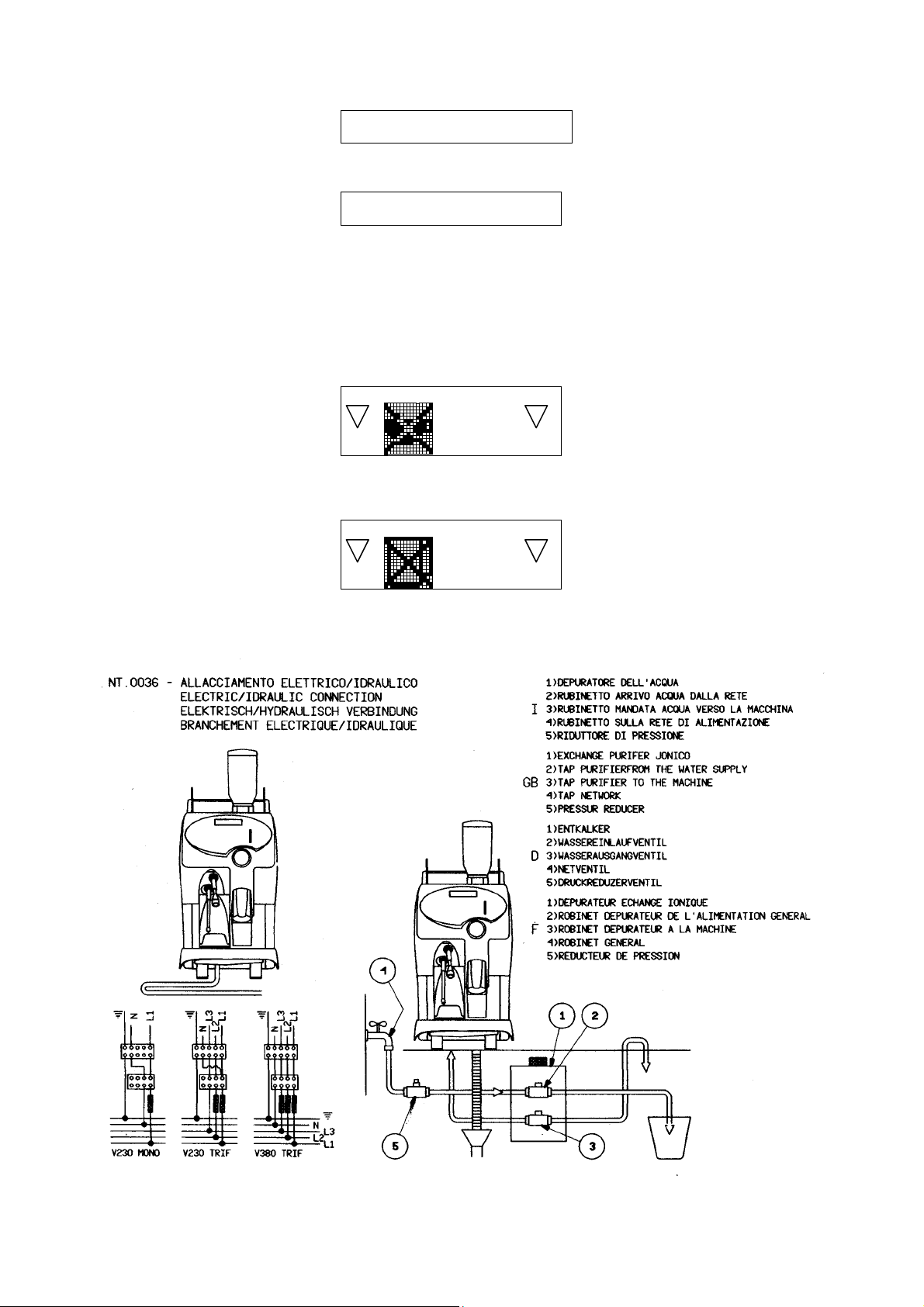
After installing the main switch and fuses (see annex), connect the power cord of the machine to the main switch according to the attached electrical
diagram.
The use of adapters, multiple power boards and extension cords is not recommended.
If it is absolutely necessary, then use only single or multiple adapters and extension cords which comply with current safety regulations, ensuring also that
the electricity load capacity of the single adapters and extension cords and the maximum power rating of the multiple adapters is suitable.
The electrical safety of this machine can be guaranteed only if correctly connected to an efficient earth circuit as indicated by current electrical safety
regulations.
It is necessary to check this fundamental safety prerequisite, and in case of doubt, ask a professionally qualified technician to check the circuit.
The manufacturer declines all responsibility for any damage caused by failure to earth the machine.
In order to avoid any dangerous overheating, we recommend that the power cord be fully unwound.
The power cord of this machine must not be replaced by customers.
In case of damage to the cord, contact exclusively a LA PAVONI Authorised Service Centre.
Do not leave the machine connected unnecessarily.
Turn off the main switch of the machine when not in use.
Do not cover the ventilation openings of the machine.
Place the machine at an adequate distance from walls, objects, etc.
The machine must be connected to a system with a water pressure, which is not greater than 5 bar. (Kg/cm
If the pressure is greater, a pressure reducer must be installed.
Install a water softener above the machine.
2
).
SPECIAL INSTRUCTIONS FOR USE AND MAINTENANCE
For a correct functioning of the machine it is fundamental to comply with the manufacturer’s instructions, having qualified personnel to carry out ordinary
maintenance and to check all safety devices.
Avoid exposing hands or other parts of the body to the coffee dispensing spouts or to the hot water nozzle. The water from the nozzle is very hot and can
cause severe burns.
The water nozzle is very hot and therefore must be handled with care, holding it in the appropriate point.
Do not use the machine without water.
Do not leave the machine in rooms where the temperature is below zero °C or 32 °F without having first drained the boiler and the hydraulic circuit.
A softener needs to be used where the water is very hard and where the calcareous scaling is particularly extensive.
In any case, regularly check the boiler even where the water is not very hard, and if necessary, have the resistors and tubing descaled by specialised
technicians.
Failure to clean La Pavoni S.p.A. machines daily, especially for brewing unit and milk frother, using approved cleaning products and following
specified cleaning procedure will result in void warranty and service contract.
383033GB Pag. 6 November 2003
Page 7

GENERAL CHARACTERISTICS
Number of coffee dispensing groups 1
Number of grinders 1
Decaffeinated door 1
Automatic cappuccino nozzle 1
Hot water dispenser 1
Maximum quantity of coffee dispensed per hour 180
Width (mm) 360
Machine height (mm) 710
Machine height with hopper (mm) 840
Depth (mm) 580
Net weight (Kg) 30
Coffee boiler capacity (lt) 2
Steam boiler capacity (lt) 2
Boiler resistor (W) Coffee
Steam
Voltage (V)
Brewer group resistor PTC (W) 70
Materials used:
- Copper for boiler
- Copper for hydraulic tubes
- Nickel-plated brass for connections.
- Reinforced silicone for the flexible feed tube.
- Aluminium with stainless steel lining for the brewing group.
- Aluminium for the grinder.
- Other accessories in food plastic which are in contact with the ground coffee or drink.
- Aluminium bodywork
- ABS plastic for controls area.
- Stainless steel and ABS plastic for working area and cups tray.
230V-1+N – 50/60Hz
230V-3 – 50/60Hz
200V-1+N – 50/60Hz
200V-3 – 50/60Hz
400V-3+N – 50/60Hz
DAYTONA 1-POWER MACHINE KEYPAD
2000
2000
383033GB Pag. 7 November 2003
Page 8
MACHINE FUNCTION MESSAGES
1) Message of machine door positioning
This message is displayed with the following symbol
Cause
: open door. The reed does not touch the magnet on the door.
: shutdown of the machine functioning.
Result
Solution
2) Message of grounds bin out of position
This message is displayed with the following symbol
Cause
Result
Solution
3) Message of full grounds bin
This message is displayed with the following symbol
Cause
Result
Solution
: close the machine door.
: grounds bin out of position. The reed does not touch the magnet on the bin.
: shutdown of coffee-based dispensing keys.
: put the grounds bin into its housing.
: full grounds bin. The number of coffee grounds in the bin has reached the value set in the programming stage.
: shutdown of coffee-based dispensing keys.
: remove the grounds bin and empty it; put the bin back in when the display shows the following symbol
4) Message of coffee boiler heating temperature not reached
This message is displayed with the following symbol
Cause: the coffee boiler has not reached the set up heating temperature
Result: shut down of coffee based dispensing.
Solution: wait until the boiler has reached the set up heating temperature.
5) Message of steam boiler heating temperature not reached
This message is displayed with the following symbol
Cause: the steam boiler has not reached the set up heating temperature
Result: shut down of milk based dispensing and hot water and steam dispensing
Solution: wait until the boiler has reached the set up heating temperature.
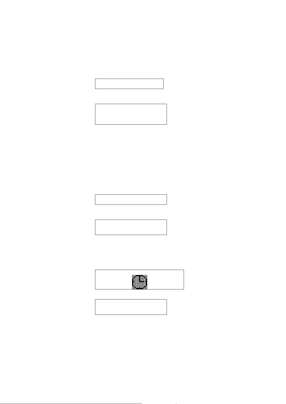
6) Message of manual group cleaning
This message is displayed with the following symbol
: the number of set group cycles has been reached
Cause
Result
: according to the type of machine set up, the results are:
a) coffee-based deliveries are disabled after 10 deliveries from display of the message
b) the relevant icon is displayed without blocking machine functioning
Solution
7) Message of milker cleaning
This message is displayed with the following symbol
Cause
Result
a) milk-based doses are disabled after 10 deliveries from display of the message
b) milk-based deliveries are disabled when the timeout set after the last milker delivery has elapsed
c) the relevant icon is displayed without blocking machine functioning
: carry out manual group cleaning.
: the number of set milker dispensing has been reached, or the set time after the last miler dispensing is over
: according to the type of machine set up, the results are:
383033GB Pag. 8 November 2003
Page 9
STARTING UP PROCEDURE
After having connected the machine to the water and electric networks, turn the switch on (see diagram). The display
shows:
LA PAVONI
REV. X.XXX
Where REV. X.XXX indicates the version of the inserted version.
After a few seconds the display shows:
SELECT LANGUAGE
ENGLISH
Press the key N°13 (1x) or N°14 (2x) to display the available languages
Press the key N°16 (3.4.5…X) to confirm the chosen language, the display shows:
OFF
Press the key N°11( ON/OFF ), the display shows:
WARNING:
If the language choice procedure is not displayed, keep the machine in OFF mode; it is absolutely
necessary to carry out PARAMETERS PRESET procedure. See system-programming chapter.
STEAM BOILER FILLING UP
During this stage the steam boiler is being filled up.
WARNING:
The solenoid valve of the steam nozzle automatically opens to release the air inside the boiler.
When the steam boiler has been filled up, the display shows:
STEAM BOILER FILLING UP
PRESS KEY N°1
AT DISPENSING
During this stage the coffee boiler is being filled up
WARNING:
The upper piston of the coffee group positions itself inside the brewing chamber, and the coffee boiler starts filling up.
When the coffee spout starts dispensing water, press the key dose N° 1 to confirm that the filling up has been carried
out. When the coffee boiler has been filled up, the display shows:
COFFEE STEAM
BOILER BOILER
XXX°C
Where:
- XXX °C indicates the temperature of the coffee boiler
- YYY ° C indicates the temperature of the steam boiler
WARNING:
YYY°C
During this stage the solenoid valve of the steam nozzle will stay open until the temperature of 95°C is
reached. This will release the air from the boiler and generate steam.
When the set up temperature of both boilers has been reached, all beverage buttons will be operative and the display
shows:
SELECT DRINK
For machine configurations: Standard or Self
383033GB Pag. 9 November 2003
Page 10
INSERT CARD
For machine configurations: waiters’ card or Self with credit card
INSERT COINS
0000
For machine configuration: Self with coin mechanism
WARNING:
a) For Self-configuration the key N° 11 (ON/OFF) is only enabled for ON function.
To turn the machine in OFF mode, insert the smart card and either press the key N°11 (ON/OFF), or open the
machine door, or use the main switch (see diagram).
b) In case of temporary voltage drop, the machine will be automatically turned back to the stage previous to the voltage
drop.
c) The display shows:
SELECT DRINK
Where the displayed icon indicates that the set up heating temperature in the coffee boiler has not been reached yet, and
therefore coffee based dispensing is not enabled; or:
SELECT DRINK
Where the displayed icon indicates that the set up heating temperature in the steam boiler has not been reached yet, and
therefore milk based dispensing and hot water and steam dispensing are not enabled.
Wait until the boiler has reached the set up heating temperature.
383033GB Pag. 10 November 2003
Page 11

MILK BOX HOLDER ASSEMBLY
The machine is supplied complete with milk box holder assembly to be fixed to the machine left side, in case the
refrigerating unit is not being used.
See drawings to fix the milk box holder
383033GB Pag. 11 November 2003
Page 12

MACHINE DISPENSING
1) STANDARD MACHINE
The display shows:
SELECT DRINK
The arrows turned downwards indicate the enabled buttons
Press the desired selection button, the display shows:
XXXXXXXX
Where XXXXXXXXX is the name of the selected drink, while the arrows indicate the key N°13 (1x) and the key N°14
(2x). Press the key “1x” to confirm single cup dispensing, press the key “2x” to confirm double cup dispensing.
Extra foamed milk function.
Extra milk function enables to dispense extra foamed milk in the following way:
- Press any milk-based key and keep it pressed, after 2 seconds foamed milk will start being dispensed.
- Releasing the pressed key, dispensing will stop.
WARNING:
a) If you want to change the type of displayed selection, press the desired selection button again, before confirming the
dispensing by means of the key buttons “1x” o “2x”.
b) If dispensing is not confirmed after 30’’ time-out, the display will cancel the chosen selection.
c) If the selection button you have pressed immediately enables the dispensing cycle, it means that the chosen
selection is activated only for a single cup.
d) Pressing any key during dispensing can stop the selected dose.
In case of a milk-based dose, press twice to stop dispensing; press once to stop milk dispensing, and once to stop
coffee dispensing; the sequence depends on the type of dispensing.
2) MACHINE WITH WAITERS’ CARD
The display shows:
INSERT CARD
Insert the smart card into the proper slit, the display shows in order:
SELECT DRINK
CARD N° XX
WAITER XX
Where N°XX indicates the number of the inserted waiters’ card, while the arrows turned downwards indicate the enabled
buttons.
Press the desired selection button, the display shows:
XXXXXXXX
Where XXXXXXXXX is the name of the selected drink, while the arrows indicate the key N°13 (1x) and the key N°14
(2x). Press the key “1x” to confirm single cup dispensing, press the key “2x” to confirm double cup dispensing.
At this point you can take the smart card out
Extra foamed milk function.
Extra milk function enables to dispense extra foamed milk in the following way:
- Press any milk-based key and keep it pressed, after 2 seconds foamed milk will start being dispensed.
- Releasing the pressed key, dispensing will stop.
383033GB Pag. 12 November 2003
Page 13

WARNING:
a) Dispensing is enabled only when the smart card is inserted.
b) The number of carried out dispensing is saved in the counter relevant to the inserted card.
c) If you want to change the type of displayed selection, press the desired selection button again, before confirming
dispensing by means of the key buttons “1x” o “2x”.
d) If dispensing is not confirmed after 30’’ time-out, the display will cancel the chosen selection.
e) If the selection button you have pressed immediately enables the dispensing cycle, it means that the chosen
selection is activated only for a single cup.
f) Pressing any key during dispensing can stop the selected dose.
In case of a milk-based dose, press twice to stop dispensing; press once to stop milk dispensing, and once to stop
coffee dispensing; the sequence depends on the type of dispensing.
3) SELF MACHINE
The display shows:
SELECT DRINK
The arrows turned downwards indicate the enabled buttons.
Press the desired selection button, the display shows:
XXXXXXXX
Where XXXXXXXXX is the name of the selected drink.
WARNING:
a) On-Off button is enabled only when the smart card is inserted
b) Extra milk function is not enabled
c) Steam function is not foreseen and not enabled
d) Decaffeinated function is not foreseen and not enabled
e) Continuous dispensing is not enabled
f) Pressing any key during dispensing can stop the selected dose.
In case of a milk-based dose, press twice to stop dispensing; press once to stop milk dispensing, and once to stop
coffee dispensing; the sequence depends on the type of dispensing.
4) SELF MACHINE WITH CREDIT CARD
The display shows:
INSERT CARD
Insert the smart card into the proper slit, the display shows the message:
SELECT DRINK
alternated with the message
CREDIT XXXXX
Where XXXXX indicates the residual credit of the inserted card.
The arrows turned downwards indicate the enabled buttons.
Place a cup under the delivery spout.
Press the desired selection button, the display shows:
XXXXXXXX
383033GB Pag. 13 November 2003
Page 14

Where XXXXXXXX is the name of the selected drink.
ATTENZIONE:
a) On-Off button is enabled only when the smart card is inserted
b) If you press a selection button before inserting the smart card, the display shows the cost of the selected drink.
c) Extra milk function is not enabled
d) Steam function is not foreseen and not enabled
e) Decaffeinated function is not foreseen and not enabled
f) Continuous dispensing is not enabled
g) The selected dose cannot be stopped.
WARNING:
To disable the functioning of the machine with credit card, proceed as follows:
Turn the machine ON.
Insert the owner or technician’s smart card into the proper slit.
Press the key N°9, the display shows:
FREE DRINKS
XXXXXXXX
Where XXXXXXX indicates:
ENABLED (Self-configuration: the machine dispenses free drinks)
DISABILITATO (Coin mechanism: the machine dispenses drinks against payment)
Press the key N°13 (1x) or N°14 (2x) to modify the level mode.
Press the key N° 12 (gost1) to return to the previous environment and/or exit.
Press the key N°16 (3.4.5…X) to confirm, the display shows:
SELECT DRINK
WARNING:
The following configurations are available: self with credit card + self with coin mechanism. In this case the
display shows: “INSERT COINS” alternated with “INSERT CARD”.
5) SELF MACHINE WITH COIN MECHANISM
The display shows:
INSERT COINS
0000
Alternated with the message:
SELECT DRINK
Where “00000” indicates the money amount inserted in the machine.
The arrows turned downwards indicate the enabled buttons.
Place a cup under the coffee spout, insert coins, press the desired button, the display shows:
XXXXXXXX
Where XXXXXX is the name of the selected dose.
WARNING:
a) On-Off button is enabled only when the smart card is inserted
b) When pressing the selection button before inserting coins, the display shows the cost of the selected drink.
c) The credit will not be returned and will be available for the next selection.
d) To get the coins back before having selected the dose, press the relevant button of the coin mechanism.
e) Extra milk function is not enabled.
f) Steam function is not foreseen and not enabled.
g) Decaffeinated function is not foreseen and not enabled.
h) Continuous dispensing is not enabled.
i) The selected dose cannot be stopped.
WARNING:
To disable the coin mechanism, proceed as follows:
Turn the machine ON
Insert the owner or technician’s smart card into the proper slit.
383033GB Pag. 14 November 2003
Page 15

Press the key N°9, the display shows:
FREE DRINKS
XXXXXXXX
Where XXXXXXX indicates:
ENABLED (Self-configuration: the machine dispenses free drinks)
DISABLED (Coin mechanism: the machine dispenses drinks against payment)
Press the key N°13 (1x) or N°14 (2x) to modify the level mode.
Press the key N° 12 (gost1) to return to the previous environment and/or exit.
Press the key N°16 (3.4.5…X) to confirm, the display shows:
SELECT DRINK
6) SELF MACHINE WITH CREDIT CARD + COIN MECHANISM
The following configurations are available: self with credit card + self with coin mechanism.
In this case the display shows:
INSERT COINS
0000
alternated with:
INSERT CARD
For further information, see the following paragraphs.
383033GB Pag. 15 November 2003
Page 16
DISPENSING BY MEANS OF DECAFFEINATED COFFEE DOOR
The display shows:
SELECT DRINK
Open the decaffeinated door, pour in the powdered coffee, close the door.
The display shows:
SELECT DRINK
Where indicates that the selected dose will be dispensed without the activation of the grinders.
WARNING:
a) If the decaffeinated door is not closed, or if the dose button is not selected, the machine will automatically cancel this
function after 20’’. The coffee group will carry out a cleaning cycle of the chamber, the display shows:
b) This function is not enabled for self machine, for self machine with credit card, for self machine with coin
mechanism, and for self with credit card + coin mechanism.
CONTINUOUS DISPENSING
The display shows:
SELECT DRINK
Press the continuous key N°16 (3.4.5…X) as many times as the number of doses you want to dispense by means of the
continuous dispensing function, maximum value is 5; the display shows:
SELECT DRINK
X
Where X
WARNING:
a) If you want to stop the automatic continuous cycle just press the continuous button N°16 (3.4.5….X).
b) This function is not enabled for the decaffeinated cycle.
c) This function is not enabled for self machine, for self machine with credit card, for self machine with coin
mechanism, and for self with credit card + coin mechanism.
Put the steam nozzle into the drink you want to heat up. Press the key N°9 to start and stop dispensing.
The display shows:
WARNING:
a) Handle the steam nozzle with caution because it could cause burns, due to high temperature.
b) The steam message will not be displayed in case another dispensing is being carried out.
c) Steam cannot be dispensed simultaneously with hot water.
d) This function is not enabled for self machine, for self machine with credit card, for self machine with coin
mechanism, and for self with credit card + coin mechanism.
indicates the number of cycles the machine will automatically carry out for the dose you will select.
STEAM DISPENSING
STEAM
383033GB Pag. 16 November 2003
Page 17

HOT WATER DISPENSING
Place the decanter under the hot water spout. Press the key N°10 to start the hot water dose. Dispensing will be
automatically stopped once the programmed dose is reached.
The display shows:
HOT WATER
WARNING:
a) Handle the hot water spout with caution because it could cause burns, due to high temperature.
b) The hot water message will not be displayed in case another dispensing is being carried out.
c) Hot water cannot be dispensed simultaneously with steam.
d) Pressing the key N°10 can stop the dose, which is being dispensed.
SMART CARD FUNCTIONS
The machine is enabled to work in the various use procedures with or without the smart card according to the desired
operation, and to the type of machine configuration.
The available smart cards are:
1) Waiters’ Smart card Card number 1-25
2) Owner’s Smart card Card number P
3) Technician’s Smart card Card number T
4) Smart credit card Card number C
5) Reading-writing Smart card Card number LS
WARNING:
a) Waiter, owner, technician and credit cards can be created on the machine control panel (see chapter system
programming, smart card programming)
b) Owner, waiter and credit cards can be converted into smart cards with other functions
c) Technician’s cards cannot be converted into any other smart card
Smart card functions:
1) Waiters’ smart card
It is possible to set maximum 25 waiters’ cards for each single machine. This card is enabled to the following functions:
1.1) In case of machine configuration: Standard, Self, Self with credit card and Self with coin mechanism:
a) Automatic washing cycles
b) Total info
1.2) In case of machine configuration with waiters’ card:
a) Dispensing
b) Automatic washing cycles
c) Reading of dispensed drinks carried out by the same card
2) Owner’s smart card
It is possible to set an infinite number of owner’s cards. This card enables the following functions:
a) Dispensing
b) Disable the functioning with coin mechanism and credit card
c) Automatic washing cycles
d) Reading of dispensed drinks carried out by waiters’ cards
e) Reading of total dispensed drinks
f) Reading of alarm data memory
g) Reset of dispensing carried out by waiters’ cards
h) Reset of total dispensing
i) Reset of water softener alarm
j) Dose programming
k) Setting of waiters’ card, owner’s card, and credit card
WARNING:
d) Dispensing carried out with this card is not counted
e) Linked remote control systems (Interface I/O, coin mechanism) are disabled.
383033GB Pag. 17 November 2003
Page 18

3) Technician’s smart card
It is possible to set an infinite number of technician’s cards. This card enables all the machine functions:
WARNING:
a) Dispensing carried out with this card is not counted
b) Linked remote control systems (Interface I/O, coin mechanism) are disabled
c) Grounds bin reed and machine door are disabled.
4) Smart credit card
It is possible to set an infinite number of cards with credit. This card enables dispensing in case the machine has been
set as “self with credit card”.
5) Reading-writing Smart card
This card enables to read all machine data, and transfer them to another machine or read them by means of a P.C.
WARNING:
a) Wait at least 2” before removing the card from its proper slit; during this time the display shows a card icon. If the
card is removed during this stage, the card might suffer irreparable damages.
b) If you use a card having a card code different from the machine code, the card can no longer been used after two
failures.
383033GB Pag. 18 November 2003
Page 19

AUTOMATIC WASHING CYCLE PROCEDURE
1) COFFEE GROUP AUTOMATIC TIMED WASHING
A timed washing cycle of the brewing chamber is automatically carried out 15’ after the last dispensed drink and every
180’ when the machine is in stand-by mode.
The display shows:
AUTOMATIC CLEANING
WARNING:
a) The timed washing cycle is not enabled for self machine, for self machine with credit card, for self machine with coin
mechanism, and for self machine with credit card + coin mechanism.
b) The parameters of water quantity and activation time of automatic washing are modifiable (see chapter: machine
data configuration).
2) AUTOMATIC TIMED RINSE OF THE CAPPUCCINO MAKER.
This is a brewing chamber washing cycle, which is carried out by the machine automatically 10 minutes after the last
dose based milk and every 3 hours.
WARNING:
You can change the interval time before the automatic wash switches on (see machine parameter management chapter).
3) GROUP-MILKER AUTOMATIC WASHING WITH DETERGENT
To enter the automatic washing mode with detergent, proceed as follows:
Turn the machine ON.
Insert the Smart Card into the proper slit.
Press the key N° 12 (gost1), the display shows:
SELECT CLEANING
T1 GROUP CLEANING
T2 MILKER CLEANING
The arrows turned downwards indicate the keys enabled to choose the type of washing:
Press the key N°1 to start group washing
Press the key N°2 to start milker washing
WARNING:
a) Before starting milker washing, remove the milk infeed pipe from the milk carton and carefully read the washing
procedure.
b) The access to this function is enabled by means of the smart card only for Self-service configurations
3.1. GROUP WASHING
It is advisable to carry out this type of washing at the end of each working day.
The display shows:
GROUP CLEANING
PLEASE WAIT
The group moves to the tablet ejecting position and the display shows:
GROUP CLEANING
Open the door and clean
Open the machine door
NT.0017
383033GB Pag. 19 November 2003
Page 20

and by using the special brush supplied, clean the group pistons and the brewing chamber.
WARNING: if you move the ejector in order to optimise manual cleaning, remember to put it back to its ejection position.
Close the door, the display shows:
GROUP CLEANING
PLEASE WAIT
The group is brought to its rest position, the display shows:
GROUP CLEANING
Insert detergent
Open the decaffeinated door nor the machine (for Self-service configurations), insert the detergent tablet and close the
decaffeinated door, the display shows:
GROUP CLEANING
Washing will automatically start; when the washing cycle is over, the display shows:
SELECT DRINK
WARNING:
a) The washing cycle is disabled after 30’’ time-out in any stage before inserting the detergent, except when the
machine door is open
b) The washing cannot be interrupted after the detergent has been inserted.
c) If the washing cycle is interrupted by any type of operation unrelated to the washing cycle, when the machine
functioning is set back again, the washing cycle will be automatically activated.
d) The hot water parameters and activation times of the washing cycle are modifiable (see chapter: group-washing
procedure).
e) The cleaning cycle can also be activated by keeping a dose key (T1-T8) pressed for about 3 seconds, if previously
configurated as “GROUP CLEANING” (see chapter beverage name programming).
The display shows:
GROUP CLEANING
Open the front door and clean
Repeat the same procedures to carry out the washing cycle.
2.2) MILKER WASHING
It is advisable to carry out this type of washing at the end of each working day
WARNING:
Before starting automatic milker washing, proceed as follows:
a) remove the milk infeed pipe from the milk carton.
b) Put the milk infeed pipe into a glass of cold water. If you use a detergent it must be liquid, no-foaming and food-type.
The display shows:
MILKER CLEANING
When the washing cycle is over, the display shows:
SELECT DRINK
383033GB Pag. 20 November 2003
Page 21

WARNING:
a) The washing cycle cannot be interrupted.
b) If the washing cycle is interrupted with any type of operation unrelated to the washing cycle, when the machine
functioning is set back again, the washing cycle will automatically be activated.
c) At the end of each working day the milker should be dismantled and cleaned by hand. To dismantle the milker,
remove the cover of the coffee-milker spout (see diagram).
d) The plunged tube needs to be periodically cleaned, therefore we suggest dismantling the two parts of the
tube(1-2) and carefully clean them, as well as the bulkhead (3) fixed on the side of the machine, by means
of the supplied brush.
WARNING:
When the washing is over, check that the milker infeed pipes are correctly connected; see below diagram:
NT.0030
383033GB Pag. 21 November 2003
Page 22

e) The cleaning cycle can also be activated by keeping a dose key (T1-T8) pressed for about 3 seconds, if previously
configurated as “MILKER CLEANING” (see chapter beverage name programming).
The display shows:
MILKER CLEANING
When the cleaning cycle is over, the display shows:
SELECT DRINK
383033GB Pag. 22 November 2003
Page 23

DOSE PROGRAMMING PROCEDURE
To enter programming mode, proceed as follows.
Insert the owner or technician’s smart card into the proper slit ,with machine ON or OFF.
Press the key N°16 (3.4.5…X) for 5 seconds, the display shows:
DOSE PROGRAMMING
SELECT BUTTON
WARNING:
a) During selection key programming, it is possible to choose another selection key, remaining in the same
programming level, if the selection key is enabled to this function
b) When the technician’s smart card is inserted the machine can be programmed even in OFF mode.
c) After 30’’ time-out, any type of mode and/or programming environment will be abandoned.
1) BEVERAGE NAME PROGRAMMING
Press a selection button, the display shows:
DOSE PROGRAMMING
SELECT NAME
TY XXXXX
Where:
T Y indicates the number of the selected button.
XXXXX indicates the name of the selected button.
Press the key N°13 (1x) or N°14 (2x) to modify the level mode.
Press the key N°16 (3.4.5…X) to confirm the modification carried out and shift to the next level
Press the key N°15 (gost2) to shift to the next level without saving the modifications carried out.
Press the key N° 12 (gost1) to return to the previous environment and/or exit.
The available choices are the following:
COFFEE-BASED DRINKS MILK-BASED DRINKS FILTER DRINKS
Kaffee creme Schnaps Cappuccino Caffè latte Pot Decanter
Espresso Kaennchen Macchiato Renversè Jug Becher
Coffee Lutz Latte macchiato Cafè au lait Filter Kaffee
Kaffee Fertig Milchkaffee Cafè chauffeur
Black coffee Grosser brauner Café 2 Espressi
Ristretto Kleiner brauner 2 Ristretti 2 Cafés
Schale Verlaengerter
Entkoffeiniert Melange ONLY-MILK DRINKS NO DRINK
Koffeinfrei Schuemli Lait chaud Latte Disabled
Fruehestueck Cafè petit dèjeuner Milk Milch
SERVICES
Sans cafèine
espresso
WARNING:
a) Depending on the type of chosen drink, the necessary programming levels will be activated to set the drink.
b) If the chosen drink refers to “FILTER DRINKS”, the coffee group cycle will be automatically modified so that ground
coffee is not pressed. Besides, additional programming levels are activated, enabling to optimise the infusion of the
selected drink.
c) If the selected name is not enabled, the button will not be enabled to dispensing.
d) If the selected name refers to “SERVICES”, the button is enabled to group or milker cleaning function (see par.
automatic cleaning cycle procedure).
Sans cafèine
caffè
Group cleaning Milker cleaning
383033GB Pag. 23 November 2003
Page 24

Descriptions of the levels of programming doses
1.1) Decaffeinated door function
This level will not be displayed for only milk drinks
DOSE PROGRAMMING
DECAFFEINATED
XXXXXXXX
Where XXXXXXX indicates:
ENABLED (the selected dose button is enabled to the use of the door to insert decaffeinated coffee)
DISABLED (the selected dose button is not enabled to the use of the door to insert decaffeinated coffee)
WARNING:
This programming level is not enabled for self machine, self with credit card and self with coin mechanism
1.2) Motor pump function during filter coffee cycle or latte macchiato
This level will be displayed only for filter drinks or for milk-based drinks
DOSE PROGRAMMING
MOTOR PUMP
XXXXXXXX
Where XXXXXXX indicates:
ENABLED (the selected dose will be dispensed by means of the motor pump)
DISABLED (the selected dose will be dispensed without the activation of the motor pump, only by using
the pressure of the hydraulic network)
WARNING:
This function is enabled in order to allow dispensing of filter drinks without using the motor pump and obtain an infusion
similar to that of percolators, that is without pressure.
1.3) Grind time programming
This level will not be displayed for only-milk drinks.
DOSE PROGRAMMING
GRIND TIME M1 XX s
GRIND TIME M2 XX s
Where XX s indicates the time in seconds during which the grinder will be activated.
WARNING:
To check the set up grind time and therefore the corresponding coffee quantity, proceed as follows:
a) Open the machine door.
b) Remove the coffee chute, disassembling the components according to the procedure shown in the picture
383033GB Pag. 24 November 2003
Page 25

c) Place a paper cup at the exit of the grinder chute to collect the coffee that will be ground.
d) Press the dose button you are programming.
e) Weigh the ground coffee obtained.
To ease the procedure, we suggest removing the upper piston, or taking out the coffee chute and directly taking the
ground coffee from the coffee outlets of the grinders.
1.4) Pre-infusion time programming
This level will not be displayed for filter and only-milk drinks.
DOSE PROGRAMMING
PRE – INFUSION X.X s
Where X.X s indicates the time in seconds necessary to wet coffee in the brewing chamber before dispensing.
1.5) Pre-infusion time programming for filter coffee cycle
This level will be displayed for filter drinks only.
DOSE PROGRAMMING
PRE – INFUSION X.X CC
Where X.X CC indicates the water quantity in cm3 necessary to wet coffee in the brewing chamber before dispensing.
1.6) Pause programming during filter coffee cycle
This level will be displayed only for filter drinks
DOSE PROGRAMMING
PAUSE XX s
Where XX s indicates the pause time in seconds carried out by the coffee group cycle after pre-infusion cycle.
WARNING: This function has been enabled to optimise the infusion of filter drinks.
1.7) Coffee water dose programming
This level will not be displayed for only milk drinks
DOSE PROGRAMMING
INFUSION XX CC
Where XX CC indicates the water quantity in cm3 of the selected dose.
1.8) Water dose programming for extra water volume
This level will be displayed only for coffee-based and filter-based drinks.
DOSE PROGRAMMING
EXTRA WATER VOLUME XX CC
Where XX CC indicates the water quantity in cm3 dispensed by means of the by-pass solenoid valve
WARNING:
The extra water dose (by-pass) is equivalent to the amount of water dispensed by the by-pass solenoid valve
simultaneously with the coffee group solenoid valve during the final dispensing stage. The amount of water set up in the
previous programming level remains the same.
1.9) Programming of steamed milk-dispensing time before coffee
This level will not be displayed for filter-based and coffee-based drinks
STEAMED MILK PRE XX s
Where XX s indicates the time in seconds during which steamed milk will be dispensed before the coffee dose.
383033GB Pag. 25 November 2003
Page 26

1.10) Programming the pause time between the PRE steamed milk and PRE foamed milk delivery.
This level will not be displayed for coffee and filter based drinks.
DOSE PROGRAMMING
PAUSE MILK PRE XX
Where XX s indicates the time in seconds of the pause between the PRE steamed milk and PRE foamed milk delivery.
PLEASE NOTE:
This function has been enabled to allow the hot milk and the frothy milk to stratify before the coffee is dispensed.
1.11) Programming of foamed milk-dispensing time before coffee
This level will not be displayed for filter-based and coffee-based drinks
DOSE PROGRAMMING
FOAMED MILK PRE XX s
Where XX s indicates the time in seconds during which foamed milk will be dispensed before the coffee dose.
1.12) Programming of pause time between milk and coffee dispensing
This level will not displayed for filter-based and coffee-based drinks.
DOSE PROGRAMMING
MILK-COFFEE PAUSE XXs
Where XX s indicates the pause time in seconds passing between milk and coffee dispensing.
WARNING:
This function has been implemented to allow steamed and foamed milk to stratify before coffee dispensing.
1.13) Programming of steamed milk-dispensing time after coffee
This level will not be displayed for filter-based and coffee-based drinks
DOSE PROGRAMMING
STEAMED MILK POST XX s
Where XX s indicates the time in seconds during which steamed milk will be dispensed after coffee doses.
1.14) Programming the pause time between the POST steamed milk and POST foamed milk delivery.
This level will not be displayed for coffee and filter based drinks.
DOSE PROGRAMMING
PAUSE MILK POST XX s
Where XX s indicates the time in seconds of the pause between the POST steamed milk and POST foamed milk
delivery.
PLEASE NOTE:
This function has been enabled to allow the hot milk and the frothy milk to stratify before the coffee is dispensed.
1.15) Programming of foamed milk-dispensing time after coffee
This level will not be displayed for filter-based and coffee-based drinks
DOSE ROGRAMMING
FOAMED MILK POST XX s
Where XX s indicates the time in seconds during which foamed milk will be dispensed after the coffee dose.
1.16) Price programming of a set up dose
DOSE PROGRAMMING
DOSE PRICE XXXXX
Where XXXXXXX indicates the dose price given to the selection button that is being programmed.
383033GB Pag. 26 November 2003
Page 27

1.17) Control of deliveries of programmed doses
DOSE PROGRAMMING
DOSE TEST
Press a dose key to carry out one delivery and check the previously set values
1.18) Programming menu function for two cups
This level will not be enabled for only milk-based drinks.
DOSE PROGRAMMING
X2 XXXXXXXXXX
Where XXXXXXX indicates:
ENABLED (the dose button is enabled to single and double dispensing (X1 e/o X2)).
DISABLED (the dose button is only enabled to single dispensing)
WARNING:
a) When the function 2X is enabled, the above menu is displayed again to set up the doses for two cups.
b) This programming level is not enabled for self machine, self with credit card, self with coin mechanism, self with
credit card + coin mechanism.
2) PROGRAMMING OF HOT WATER DOSE FOR TEA
Press hot water button, the display shows:
2.1) Programming hot water dose for tea
DOSE PROGRAMMING
HOT WATER
WATER XXX.X
where XXX.X indicates the time in seconds during which hot water will be dispensed; the value varies between 0-120s;
10s are the standard set up value.
Press the key N°13 (1x) or N°14 (2x) to modify the level mode.
Press the key N°16 (3.4.5…X) to confirm the modification carried out and shift to the next level
Press the key N°15 (gost2) to shift to the next level without saving the modifications carried out.
Press the key N° 12 (gost1) to return to the previous environment and /or exit.
2.2) Price programming of a set up dose
DOSE PROGRAMMING
DOSE PRICE XXXXX
where XXXXX indicates the dose price given to the selection button that is being programmed.
WARNING:
If the dose is programmed to zero, the button is disabled.
3) STEAM DISPENSING TIME PROGRAMMING
Press the hot water key, the display shows:
3.1) Steam dispensing time programming
DOSE PROGRAMMING
STEAM TIME
XXX
383033GB Pag. 27 November 2003
Page 28

where XXX indicates the time in seconds during which steam will be dispensed; the value varies between 0-255s; 255s
are the standard set up value.
Press the key N°13 (1x) or N°14 (2x) to modify the level mode.
Press the key N°16 (3.4.5…X) to confirm the modification carried out and shift to the next level
Press the key N°15 (gost2) to shift to the next level without saving the modifications carried out.
Press the key N° 12 (gost1) to return to the previous environment and /or exit.
3.2) Price programming of a set up dose
DOSE PROGRAMMING
DOSE PRICE XXXXX
where XXXXX indicates the dose price given to the selection button that is being programmed.
WARNING:
If the dose is programmed to zero, the button is disabled.
SYSTEM TEMPERATURE INFORMATION PROCEDURE
To enter the environment of info temperature system, proceed as follows:
Turn the machine ON or OFF.
Press the key N° 15 (gost2), the display shows:
INFO TEMPERATURE SYSTEM
COFFEE TEMPERA. XX°Z
STEAM TEMPERA.YY°Z
Where:
XX°C indicates the temperature of the coffee boiler, and Z indicates the unit expressed in ° Centigrade or ° Fahrenheit
YY°C indicates the temperature of the steam boiler, and Z indicates the unit expressed in ° Centigrade or ° Fahrenheit
WARNING:
a) The system temperatures will be displayed for 5”.
b) This function is enabled without the use of the smart card
INFORMATION PROCEDURE AND DISPENSING RESET
To enter the information environment and dispensing reset, proceed as follows:
Turn the machine ON
Insert the smart card into the proper slit
Press the key N°15 (gost2), the display shows:
DISPENSING INFO
DOSE READING
Press the key N°16 (3.4.5…X) to confirm entering the environment
Press the key N°13 (1x) or N°14 (2x) to display the available environments
Press the key N° 12 (gost1) to exit the environment
The display shows:
DISPENSING INFO
DOSE READING
DISPENSING INFO
WAITERS’ DOSE
RESET
383033GB Pag. 28 November 2003
Page 29

WARNING:
a) Dispensing info environment of the waiters’ card reset is only enabled by means of machine configuration “waiters”.
b) Dispensing info environment of the waiters’ card reset is only enabled by means of the owner or technician’s card.
Descriptions of information environments and dose reset:
1) READ DOSE COUNTER
1.1) In case of machine configuration: standard, self, self with credit card, self with coin mechanism, self with credit
card + coin mechanism, the display shows:
DISPENSING INFO
READ DOSE COUNTER
Press N°16 (3.4.5…X) to confirm entering the environment, the display shows:
DISPENSING INFO
TOTAL TAKINGS
XXXXXXXX
Where XXXXXXXX indicates the total takings of the machine
WARNING:
The total takings will be calculated if a selling price has been set for each dose
Press the key N° 16 (3.4.5…X) to confirm entering the next environment, the display shows:
DISPENSING INFO
READ DOSE COUNTER
SELECT BUTTON
Press the key dose whose number of drinks you want to display; the display shows:
DISPENSING INFO
READ DOSE COUNTER
XXXXX
1X YY 2X ZZ ♥ JJ
Where: “XXXX” indicates the name of the selected button
1X YY indicates the number of single cup dispensed drinks
2X ZZ indicates the number of double cup dispensed drinks
♥ JJ indicates the number of decaffeinated dispensed drinks
1.2) In case of machine configuration with waiters’ card, the display shows:
DISPENSING INFO
READ DOSE COUNTER
Press the key N°16 (3.4.5…X) to confirm entering the environment, the display shows:
DISPENSING INFO
READ DOSE COUNTER
WAITER 1
Where 1 indicates the number of the waiter’s card.
Press the key N°13 (1x) or N°14 (2x) to change the number of the waiter’s card or the machine total T
Press the key N° 12 (gost1) to exit the environment.
Press the key N°16 (3.4.5…X) to confirm, the display shows:
DISPENSING INFO READ
DOSE COUNTER WAITER Y
TOTAL TAKINGS
XXXXXXXX
383033GB Pag. 29 November 2003
Page 30
Where Y indicates:
from 1 to 25 the waiter’s number
T all the waiters.
Where XXXXXXXX indicates the total takings made by the relevant waiter 1-25 or by all the waiters T.
WARNING:
The total takings will be calculated if a selling price has been set for each dose
Press the key N° 16 (3.4.5…X) to confirm entering the next environment, the display shows:
DISPENSING INFO READ
DOSE COUNTER WAITER 1
Press the key dose whose number of drinks you want to display; the display shows:
DISPENSING INFO READ
DOSE COUNTER WAITER 1
XXXXX
1X YY 2X ZZ ♥ JJ
Where: “XXXX” indicates the name of the selected button
1X YY indicates the number of single cup dispensed drinks
2X ZZ indicates the number of double cup dispensed drinks
♥ JJ indicates the number of decaffeinated dispensed drinks
Press the key (gost1) to return to the level enabling to select the card number.
WARNING:
a) If the waiters’ card is inserted, it is not possible to display info about other cards.
b) If the owner or technician’s card is inserted, info about each waiter card or of all the waiters’ key can be displayed.
2) WAITER DOSE RESET
The display shows:
DISPENSING INFO
WAITER DOSE REST
Press the key N°16 (3.4.5…X) to display the next level, the display shows:
DISPENSING INFO
DOSE RESET
WAITER’S CARD N° XX
Where XX indicates the number of the waiter’s card you want to reset.
Press the key N°13 (1x) or N°14 (2x) to display the number of the desired waiter’s card.
Press the key N°16 (3.4.5…X) to confirm the number of the waiter’s card.
Press the key N° 12 (gost1) to exit the environment.
The display shows:
WAITER’S CARD RESET N°XX
After 3” the display shows:
DISPENSING INFO
DOSE RESET
WAITER’S CARD N° XX
Repeat the above procedures to reset the other waiters’ cards.
383033GB Pag. 30 November 2003
Page 31

SMART CARD CREDIT CHARGE PROCEDURE
This procedure is enabled only for the following machine configurations: self with credit card, self with credit card + coin
mechanism.
To enter the credit charge environment, proceed as follows:
Turn the machine in ON mode
Insert the owner or technician’s smart card into the proper slit.
Press the key N°16 (3.4.5…X), the display shows:
SYSTEM PROGRAMMING
CREDIT CHARGE
Press the key N°16 (3.4.5…X) to confirm entering the environment.
The display shows:
SYSTEM PROGRAMMING
CREDIT CHARGE
INSERT SMART CARD
Remove the technician or owner’s card, and insert the card where you want to programme the credit.
Once the card to be programmed has been inserted, the display will automatically show the machine device code:
SYSTEM PROGRAMMING
CARD CODE
XXXX
X
Insert the code relevant to the card to be programmed.
To insert the card code, proceed as follows:
The blinking X
Press the key N°13 (1x) or N°14 (2x) to modify the figure.
Press the key N°16 (3.4.5…X) to confirm the modification.
Press the key N°15 (gost2) to enter the next level without saving the modification carried out.
Press the key N° 12 (gost1) to return to the previous environment and/or exit.
After having modified the first figure and confirmed the operation, the display shows:
Where the blinking X
Repeat the above operations for all the other figures.
Once the card code has been entered, the display shows:
a)
Where:
XXXXXXX indicates the residual card credit
YYYYYYY indicates the value that can be added to the card
Press the key N°13 (1x) or N°14 (2x) to modify the value to be credited.
Press the key N°16 (3.4.5…X) to confirm the modification.
Press the key N°15 (gost2) to enter the next level without saving the modification carried out.
Press the key N° 12 (gost1) to return to the previous environment and/or exit.
The display shows:
number indicates the first figure of the code to be modified:
SYSTEM PROGRAMMING
CARD CODE
XX
XXX
number indicates the second figure to be modified, etc. etc.
SYSTEM PROGRAMMING
CREDIT CHARGE
CURRENT CREDIT XXXXXXX
ADD YYYYYYY
SYSTEM PROGRAMMING
CARD CODE
FUCNTION OVER
383033GB Pag. 31 November 2003
Page 32

Remove the created credit card, the display shows:
SYSTEM PROGRAMMING
INSERT CARD
XXXXXXXX
Where XXXXXXXX indicates:
TECHNICIAN if the card inserted to enable the programming of the waiter’s card was the technician’s
OWNER if the card inserted to enable the programming of the waiter’s card was the owner’s.
Insert the requested card, the display shows:
SYSTEM PROGRAMMING
CREDIT CHARGE
WARNING:
The value that can be inserted is determined by the difference between the maximum programming value of the card
(value that is fixed in the environment “system programming, machine parameters”) and the residual credit of the
inserted card.
b)
CREDIT CHARGE
CARD CODE
NOT VALID
This message is displayed if the inserted card code does not correspond to that of the inserted card.
Remove the card to be reprogrammed, the display shoes:
CREDIT CHARGE
INSERT CARD
XXXXXXXX
Where XXXXXXXX indicates
TECHNICIAN if the card inserted to enable the programming of the waiter’s card was the technician’s
OWNER if the card inserted to enable the programming of the waiter’s card was the owner’s.
Insert the requested card, the display shows:
SYSTEM PROGRAMMING
CREDIT CHARGE
Repeat the procedure.
WARNING:
After 4 (four) failed attempts the card can no longer be used
c)
SYSTEM PROGRAMMING
BROKEN CARD
This message is displayed if one has repeatedly tried to programme the card and a wrong card code has been entered.
The card can no longer be used.
Press the key N°16 (3.4.5…X), the display shows:
SYSTEM PROGRAMMING
SMART CARD PROGRAMMING
383033GB Pag. 32 November 2003
Page 33
SYSTEM PROGRAMMING
To enter the system-programming environment, proceed as follows:
Turn the machine OFF.
Insert the owner or technician’s smart card into the proper slit.
Press the key N°16 (3.4.5.), the display shows:
SYSTEM PROGRAMMING
MACHINE PARAMETERS
Press the key N°13 (1x) or N°14 (2x) to display the available environments.
Press the key N°16 (3.4.5…X) to confirm entering the desired environment.
Press the key N° 12 (gost1) to return to the previous environment and/or exit.
SYSTEM PROGRAMMING
PROGRAMMING
GROUP CLEANING
SYSTEM PROGRAMMING
PROGRAMMING
MILKER CLEANING
SYSTEM PROGRAMMING
SET-UP ENCODER
SYSTEM PROGRAMMING
GROUP MANUAL MOVEMENTS
SYSTEM PROGRAMMING
TEST ACTUATORS
SYSTEM INFORMATION
RESET DOSES COUNTER
SYSTEM DATA
SYSTEM PROGRAMMING
ALARM DATA MEMORY
SYSTEM PROGRAMMING
SMART CARD PROGRAMMING
SYSTEM PROGRAMMING
PRESET CONFIGURATION DATA
SYSTEM PROGRAMMING
FILE MANAGER
SYSTEM PROGRAMMING
UPDATE SOFTWARE
SYSTEM PROGRAMMING
HISTORY HIGER MOTOR
SYSTEM PROGRAMMING
HISTORY LOWER MOTOR
Descriptions of the machine programming environments:
1) MACHINE PARAMETERS
Only the technician’s card is enabled to enter this environment.
The display shows:
383033GB Pag. 33 November 2003
Page 34

SYSTEM PROGRAMMING
MACHINE PARAMETERS
Press the key N°16 (3.4.5…X) to display the available levels.
Press the key N°13 (1x) or N°14 (2x) to modify the level mode.
Press the key N°16 (3.4.5…X) to confirm the modification and shift to the next level
Press the key N°15 (gost2) to shift to the next level without saving carried out the modifications.
Press the key N° 12 (gost1) to return to the previous environment and/or exit.
1.1) Language selection programming
MACHINE PARAMETERS
LANGUAGE
XXXXXXX
Where XXXXXX indicates the type of set up language: Italian, English, German, and French.
1.2) Machine type configuration programming
MACHINE PARAMETERS
MACHINA CONFIGURATION
XXXXXXX
Where XXXXXX indicates:
STANDARD (the machine works without the use of waiters’ smart card)
WAITERS’ CARD (the machine works with the use of waiters’ smart card only)
SELF (the machine works as Self Service version)
SELF with Credit card (the machine works with the use of the smart credit card)
SELF Credit card +COIN MECHANISM
(the machine works with the use both of the smart credit card and coin mechanism)
1.3) Serial door function
MACHINE PARAMETERS
SERIAL
XXXXXXXX
Where XXXXXX indicates:
Disabled (the machine works without connected peripheral)
I/O HARTWALL (the machine works with connected interface I/O)
RM5Coin Box (the machine works with connected standard coin mechanism)
Change Giver Executive (the machine works with Executive protocol to run external devices, not sold by la Pavoni
for instance change giver coin mechanism)
1.4) Coffee grounds number programming
MACHINE PARAMETERS
GROUNDS NUMBER XX
Where XX indicates the set up grounds number, variable value between 0-100, 60 set up standard value.
WARNING:
XX (The machine works with the use of coffee grounds bin; when the set up grounds number is
reached, the relevant message “grounds bin full” will be displayed)
00 (The machine works without the use of coffee grounds bin; direct grounds discharge installed)
1.5) Automatic cleaning function
MACHINE PARAMETERS
AUTO CLEANING
XXXXXXXX
Where XXXXXXX indicates:
ENABLED (the machine automatically carries out coffee group cleaning)
DISABLED (the machine does not carry out coffee group cleaning automatically)
If automatic cleaning is activated, the following programming levels are displayed:
383033GB Pag. 34 November 2003
Page 35

1.5.a) Water dose programming for automatic cleaning
MACHINE PARAMETERS
AUTO CLEANING
WATER XX CC
Where XX CC indicates set up water quantity, which will be dispensed; variable value between 0-300CC; 70cc set up
standard value.
1.5.b) Start time programming of automatic cleaning after the last coffee
MACHINE PARAMETERS
AUTOMATIC CLEANING
T.O. AFTER COFFEE XX min
Where XX min indicates set up time in minutes passed between the last drink dispensed and the first automatic cleaning
cycle; variable value between 0-255’; 15’ set up standard value.
1.5.c) Time programming between one cleaning cycle and the next
MACHINE PARAMETERS
AUTO CLEANING
T.O. REPETITION XX min
Where XX min indicates the set up time in minutes passed between the first automatic washing and the next one;
variable value between 0-255’; 180’ set up standard value.
1.6) Programming rinse after milk dose.
RINSE AFTER MILK DOSE
XXXXXXXX
Where XXXXXXX indicates:
ENABLED (the machine automatically carries out a rinse after milk dose)
DISABLED (the machine does not carry out a rinse after milk automatically)
- If this parameter is enabled, a rinse at end of every dose milk based starts automatically.
- The start of the cleaning may be changed by programming a time pause , the following programmation livel will be displayed :
1.6a) Programming pause rinse after milk dose.
RINSE AFTER MILK DOSE
PAUSE AFTER MILK SEC.
XXX
Where Sec. XXX indicates the time in seconds of the pause between the end of milk dose and the start of rinse.
variable value between 3” - 10” ; 3” set up standard value.
1.7) Automatic rinse milker machine in stand-by .
RINSE AFTER MILK STAND-BY
XXXXXXXX
Where XXXXXXX indicates:
ENABLED (the machine automatically carries out coffee milker rinsing)
DISABLED (the machine does not carry out milker rinsing automatically)
If automatic cleaning is activated, the following programming levels are displayed:
383033GB Pag. 35 November 2003
Page 36

1.7.a) Start time programming of automatic milker rinse after the last dose milk based.
RINSE AFTER MILK STAND-BY
PAUSE XX MIN
Where XX min indicates set up time in minutes passed between the last drink milk based dispensed and the first
automatic rinsing cycle; variable value between 1'-10’; 10' set up standard value.
1.7.b) Time programming between one milker rinse cycle and the next.
RINSE AFTER MILK STAND-BY
REPETITION XX MIN
Where XX min indicates the set up time in minutes passed between the first automatic milker rinsing and the next one;
variable value between 1'-180' ; 180’ set up standard value.
1.8) M1 tools working time programming for maintenance
MACHINE PARAMETERS
TOOLS WORKING TIME 1
XXX
Where M1 XXX h indicates the time in hours of set up functioning for the grinder tools M1 ; variable value between 0-
999; 300 set up standard value.
1.9) Water filter litre programming
MACHINE PARAMETERS
WATER FILTER LITRES
XXXX
Where XXXX indicates the set up number of water filter litres; variable value between 0-15000; 5000 set up standard
value.
WARNING:
XXXX (The machine works with the water filter; when the set up number of litres has been reached,
the relevant message to renew the water filter is displayed)
00 (The machine works without counting water filter litres)
1.10) Group cycle number programming for maintenance
MACHINE PARAMETERS
GROUP CYCLES
XXXX
Where XXXX indicates the set up number of group cycles; variable value between 0-65000
WARNING:
10000 (The number of group cycles is enabled; when the set up number of cycles has been reached,
the relevant message to verify the group is displayed).
00 (The machine works without counting the number of group cycles).
If you set up a value higher than zero, the display shows:
MACHINE PARAMETERS
MACHINE SHUTDOWN
XXXX
Where XXXX indicates:
YES (the machine shuts down when the set up number of cycles has been reached).
NO (the machine does not shut down when the set up number of cycles has been reached).
383033GB Pag. 36 November 2003
Page 37

1.11) Group cycle number programming for manual group cleaning message
MACHINE PARAMETERS
GROUP CLEANING ALARM
XXXX
Where XXXX indicates the programmed group cycle number; variable value between 0-10000; 0 set up standard value.
WARNING:
XXXX (The machine will display the message manual group cleaning when the set up cycle number has been
reached)
0 (The machine works without counting the group cycle number)
1.12) Programming blocked deliveries message of group cleaning
This programming level is displayed, if a value higher than zero is inserted in the programming of the dispensing number
message of group cleaning, the display shows:
MACHINE PARAMETERS
GROUP CLEANING ALARM
STOP DRINK
XXXX
Where XXXX indicates:
ENABLED a) coffee-based deliveries are disabled after 10 deliveries from display of the message
DISABLED b) the message is displayed without disabling deliveries
1.13) Dispensing number programming for milker cleaning message
MACHINE PARAMETERS
MILKER CLEANING ALARM
CYCLES XXXX
Where XXXX indicates the programmed number of milk-based dispensing; variable value between 0-10000; 0 set up
standard value.
WARNING:
XXXX (The machine will display the message manual milker cleaning when the programmed dispensing
number has been reached)
0 (The machine works without counting the milker dispensing number)
1.14) Programming of time out message of milker cleaning
MACHINE PARAMETERS
MILKER CLEANING ALARM
TIME X min.
Where X min. indicates the programmed time in min.; variable value between 0-60; 0 set up standard value.
WARNING:
XXXX (The machine will display the message manual milker cleaning when the time set after the last milker
dispensing is running out)
0 (The machine works without counting the time out)
1.15) Programming blocked deliveries message of milker cleaning
This programming level is displayed, if a value higher than zero is inserted in the programming of the dispensing number
message of milker cleaning, the display shows:
MACHINE PARAMETERS
MILKER CLEANING ALARM
STOP DRINK
XXXX
Where XXXX indicates:
ENABLED a) milk-based doses are disabled after 10 deliveries from display of the message
b) milk-based deliveries are disabled when the timeout set after the last milker delivery has elapsed
DISABLE the message is displayed without disabling deliveries
383033GB Pag. 37 November 2003
Page 38

1.16) Coffee temperature unit programming
MACHINE PARAMETERS
TEMPERATURE UNIT
X
Where X indicates:
°C (the machine works with temperature unit expressed in ° Centigrade).
°F (the machine works with temperature unit expressed in ° Fahrenheit).
1.17) Currency decimal number programming
MACHINE PARAMETERS
DECIMAL PRICES X
Where X indicates the decimal number to display one price; variable value between 0-3 (1=decimal, 2= hundredth, 3 =
thousandth); set up standard value 0.
1.18) Minimum currency unit programming
MACHINE PARAMETERS
SCALE OF PRICES X
Where X indicates the value of the minimum currency unit that is being used; variable value between 1-65500; set up
standard value 50.
1.19) Maximum credit programming of the credit card
MACHINE PARAMETERS
CARD MAXIMUM CREDIT
XXXXX
Where X indicates the maximum credit value that can be programmed on the credit card; variable value between 0infinite; set up standard value 50.000.
1.20) Coffee boiler temperature programming
MACHINE PARAMETERS
COFFEE TEMPERAT. XX °Y
Where XX indicates the set up coffee boiler temperature and °Y indicates the unit expressed in ° Centigrade or °
Fahrenheit; variable value between 75-95 °C; 90°C set up standard value.
1.21) Steam boiler temperature programming
MACHINE PARAMETERS
STEAM TEMPERAT. XXX °Y
Where XXX indicates the set up steam boiler temperature and °Y indicates the unit expressed in ° Centigrade or °
Fahrenheit; variable value between 110-124 °C; 122 °C set standard value.
1.22) Programming of steam boiler heating time at each water filling up
MACHINE PARAMETERS
STEAM HEATER TIME
XX SEC
Where XX SEC indicates the time during which the heating of the steam boiler is automatically activated every time
water is filled up into the steam boiler to reset the standard level; variable value between 0-15 “; 8” set up standard value.
WARNING:
This function has been implemented to avoid that the cold water, which is filled to reset the level, may cause the boiler
temperature to drop.
383033GB Pag. 38 November 2003
Page 39

1.23) Programming the Time-Out between one milk-based delivery and the next.
This level is enabled only for milk-based doses.
MACHINE PARAMETERS
WAITING TIME
MILK DOSE A-B XX min.
Where XX min. indicates the Time-Out in minutes between one milk-based dose and the next. Once it has elapsed, it will
automatically increase the quantity of milk for the next dose.
PLEASE NOTE:
The milk lengthening programming parameter will only be displayed if you enter a number over zero.
1.24) Programming the milk lengthening time.
This level is enabled only for milk-based drinks.
MACHINE PARAMETERS
ADDITIONAL MILK XX s
Where XX s indicates the milk lengthening time in seconds of the first dose, which will be delivered as soon as the Timeout has elapsed, between one milk-based dose and the next, in order to obtain deliveries of the same volume.
PLEASE NOTE:
This level will be displayed only if you enter a number over zero in the Time-out programming parameter between one
milk-based delivery and the next.
1.25) Programming of temperature drain stop of steam boiler
Where XX indicates the steam boiler temperature and °Y indicates the unit in ° Centigrade or ° Fahrenheit; variable value
between 0-95 °C; 95°C set up standard value.
WARNING:
This function has been implemented to open the steam nozzle solenoid valve and release air from the boiler during the
programming stage. The solenoid valve will remain excited until the set up temperature has been reached.
1.26) Sequential heating functions of coffee and steam boilers
Where XXXXXXX indicates:
ENABLED (the machine carries out a sequential heating of coffee-steam boilers with priority to the coffee
boiler).
DISABLED (the machine carries out simultaneous, rather than sequential, heating).
1.27) Programming Button N°16 function
Where XXXXXXX indicates:
CONTINUOUS (the N°16 button is enabled for continuous dispensing function, maximum value is ( see
Continuous dispensing Paragraph)
GRINDER SHIFT (the N°16 button is enabled for grinder change function , ( see Grinder Change Function
Paragraph)
1.28) Programming temperature probe type .
Where XXXXXXX indicates:
100K (the machine is enabled for 100k probes , old version)
3K3 (the machine is enabled for 3k probes , new version)
MACHINE PARAMETERS
DRAIN TEMPERAT. XX °Y
MACHINE PARAMETERS
SEQUEN. HEATING
XXXXXXXX
MACHINE PARAMETERS
BUTTON N°16 FUNCTION
XXXXXXXX
MACHINE PARAMETERS
TEMPERATURE PROBE TYPE
XXXX
383033GB Pag. 39 November 2003
Page 40

ATTENTION:The software default value is 3k3. Is necessary to shift 100k in machines equipped wiht the old probes.
1.29) Programming maximum higer motor impulses
MACHINE PARAMETERS
MAX. H. MOT.IMPULS.
XXX
In this parameter, set the number of pulses corresponding to the maximum stroke of the upper motor, that you have
previously noticed in the Manual Movements. (see position 2 on NT 0068)
1.30) Programming higer motor stand-by position impulses
MACHINE PARAMETERS
H.MOT. STAND-BY POSIT.IMPUL.
XXX
In this parameter, set the number of pulses which will stop the upper motor stroke when moving to stand-by position.
The default value is 20, i.e. the piston will stop its stroke 20 pulses before the mechanical end.
(see position 3 on NT 0068)
1.31) Programming higer motor delivery position impulses
MACHINE PARAMETERS
H.MOT. DELIVERY POSIT.IMPUL.
XXX
In this parameter, set the number of pulses which will stop the upper motor stroke when moving to dispensing position.
For instance, if the maximum stroke is 575 pulses, you will set 555 pulses: the piston will stop its stroke 20 pulses before
the mechanical end. (see position 4 on NT 0068)
1.32) Programming maximum lower impulses
MACHINE PARAMETERS
MAX. L. MOT.IMPULS.
XXX
In this parameter, set the number of pulses corresponding to the maximum stroke of the lower motor, that you have
previously noticed in the Manual Movements. (see position 2 on NT 0068)
1.33) ) Programming lower motor stand-by position impulses
MACHINE PARAMETERS
L.MOT. STAND-BY POSIT.IMPUL.
XXX
In this parameter, set the number of pulses which stops the lower motor stroke when moving to stand-by position.
The default value is 20, i.e. the piston will stop its stroke 20 pulses before the mechanical end.
(see position 3 on NT 0068)
1.34) Programming lower motor expelling position impulses
MACHINE PARAMETERS
L. MOT. EXPELLING POSIT.IMPUL.
XXX
383033GB Pag. 40 November 2003
Page 41

In this parameter, set the number of pulses which will stop the upper motor stroke when moving to expelling position.
For instance, if the maximum stroke value is 552, you will set 532 pulses: the piston will stop its stroke 20 pulses before
the mechanical end. (see position 4 on NT 0068)
2) GROUP CLEANING PROGRAMMING
Only the technician’s card can enter this programming level
The display shows:
SYSTEM PROGRAMMING
GROUP CLEANING
PROGRAMMING
Press the key N°16 (3.4.5…X) to display the available levels.
Press the key N°13 (1x) or N°14 (2x) to modify the level mode.
Press the key N°16 (3.4.5…X) to confirm the modification and shift to the next level
Press the key N°15 (gost2) to shift to the next level without saving carried out modifications.
Press the key N° 12 (gost1) to return to the previous environment and/or exit.
2.1) Water dose programming for automatic cleaning with detergent
GROUP CLEANING PROG.
WATER VOLUME XXX CC
Where XX CC indicates the water quantity in cm3 set up for cleaning; variable value between 0-3000 CC; 300 CC set up
standard value.
WARNING:
This programming level sets the water quantity, which will be dispensed at every stage of the cleaning cycle, except
when the detergent is being wet.
2.2) Pause time programming during automatic cleaning with detergent
GROUP CLEANING PROG.
PAUSE XX s
Where XX s indicates the pause time in seconds carried out by the coffee group cycle after inserting the detergent;
variable value between 0-60 s; 30 s set up standard value.
WARNING:
This programming level sets the pause time between the stages of the washing cycle; this function has been
implemented to optimise the action of the detergent.
2.3) Programming of cycle number
GROUP CLEANING PROG.
REPETITIONS X
Where X indicates the number of the cycles carried out by the group during the cleaning cycle, variable value between 25; 2 set up standard value.
WARNING:
This programming level sets the number of cleaning cycles of the brewing chamber. During this stage the coffee group
dispenses water with the opening of the group signal solenoid valve; this function has been implemented to optimise the
washing of the group solenoid valve
3) MILKER CLEANING PROGRAMMING
Only the technician’s card can enter this programming level
The display shows:
SYSTEM PROGRAMMING
MILKER CLEANING
PROGRAMMING
Press the key N°16 (3.4.5…X) to display the available levels.
Press the key N°13 (1x) or N°14 (2x) to modify the level mode.
Press the key N°16 (3.4.5…X) to confirm the modification and shift to the next level.
Press the key N°15 (gost2) to shift to the next level without saving carried out modifications.
Press the key N° 12 (gost1) to return to the previous environment and/or exit.
383033GB Pag. 41 November 2003
Page 42

3.1) Milker cleaning time programming
MILKER CLEANING
PROGRAMMING
CLEANING TIME XX s
Where XX s indicates the Milker cleaning time in seconds; variable value between 1-120 s; 60 s set up standard value.
WARNING:
During Milker cleaning the solenoid valve opens at signals; this function has been implemented to optimise Milker
cleaning.
4) SET-UP ENCODER
Only the technician’s card can enter this programming level
The display shows:
SYSTEM PROGRAMMING
SET-UP ENCODER
Press the key N°16 (3.4.5…X) to confirm the operation.
Press the key N° 12 (gost1) to return to the previous environment and/or exit.
The display shows:
GROUP MANUAL MOVEMENTS
HIGHER MOTOR XXX
MOTOR EXPELLER
LOWER MOTOR XXX
Where XXX indicates the impulses of the upper and lower motor.
Press the keys:
N°1 to move the upper piston
N°3 to move the lower piston
Please Note: this function allows to read the maximum strokes of the two pistons:
- starting from stand-by position, move the lower and upper motors to their mechanical ends of stroke (see
position 1-2 on NT 0068).
- the maximum stroke of each piston is shown in the display by the related number of pulses.
5) GROUP MANUAL MOVEMENTS
Please Note : This function will be displayed only after having set the encoder
Only the technician’s card can enter this programming level
The display shows:
SYSTEM PROGRAMMING
GROUP MANUAL MOVEMENTS
Press the key N°16 (3.4.5…X) to confirm the operation.
Press the key N° 12 (gost1) to return to the previous environment and/or exit.
The display shows:
GROUP MANUAL MOVEMENTS
HIGHER MOTOR
MOTOR EXPELLER
LOWER MOTOR
Press the keys:
N°1 to move the upper piston
N°2 to move the expeller
N°3 to move the lower piston
WARNING:
Once the desired movement has been completed, by pressing the same button, the opposite movement is carried out.
383033GB Pag. 42 November 2003
Page 43

6) TEST ACTUATORS
Access enabled with technical card.
The display shows:
SYSTEM PROGRAMMING
TEST ACTUATORS
Press key No. 16 (3.4.5…X) to confirm the operation.
Press key No. 12 (gost1) to return to the previous programming environment and/or exit.
The display shows:
TEST ACTUATORS
Press the key activating the actuator that you wish to check. (See the key reference table)
Press the previously pressed key again to stop the activated actuator from working.
PLEASE NOTE:
- you can activate more than one actuator at the same time.
- once a time-out of 10 seconds has elapsed, the activated actuators will be automatically interrupted.
383033GB Pag. 43 November 2003
Page 44

7) SYSTEM DATA RESET INFO
The owner and technician’s cards can enter this programming level
The display shows:
SYSTEM PROGRAMMING
SYSTEM DATA
RESET INFO
Press the key N°16 (3.4.5…X) to confirm entering the environment.
Press the key N°13 (1x) or N°14 (2x) to display the available environments
Press the key N° 12 (gost1) to return to the previous environment and/or exit.
The display shows:
RESET INFORMATION
TOTAL DOSE RESET
RESET INFORMATION
GROUP CLEANING
XXXX
RESET INFORMATION
MILKER CLEANING
XXXX
RESET INFORMATION
GROUP CYCLES
XXXX
RESET INFORMATION
TOOLS TIME
M1 XXXX h
RESET INFORMATION
SYSTEM DATA
WATER FILTER LITRES
XXXX L
RESET INFORMATION
TOTAL GROUP CYCLES
XXXX L
WARNING:
1) The owner’s card can only enter total dose reset environment and water softener alarm reset.
2) Environments: group cycles, M1 tools time, and water filter litres will be displayed only if values higher than 000
(zero) have been set during the programming stage.
Descriptions of system programming environments of information reset.
7.1) Reset of total dispensing number carried out by selection buttons
RESET INFORMATION
TOTAL DOSE RESET
Press the key N°16 (3.4.5…X) to confirm the reset; the display shows:
INFO RESET
TOTAL DOSE RESET
CONFIRM RESET
Press the key N°16 (3.4.5…X) to confirm reset, the display shows in order:
INFO RESET
DOSE RESET
383033GB Pag. 44 November 2003
Page 45

INFO RESET
TOTAL DOSE RESET
Press the key N° 12 (gost1) to return to the previous environment and/or exit.
7.2) Reading-reset of automatic group cleaning number with detergent
RESET INFORMATION
GROUP CLEANING
XXXX
Where XXXX indicates the number of group cleaning carried out.
Press the key N°16 (3.4.5…X) to display the next level; the display shows:
RESET INFORMATION
GROUP CLEANING
CONFIRM RESET
Press the key N°16 (3.4.5…X) to confirm reset, the display shows:
RESET INFORMATION
GROUP CLEANING
0
Press the key N° 12 (gost1) to return to the previous environment and/or exit.
7.3) Reading-reset of milker cleaning number
RESET INFORMATION
MILKER CLEANING
XXXX
Where XXXX indicates the number of milker cleaning carried out.
Press the key N°16 (3.4.5…X) to display the next level; the display shows:
RESET INFORMATION
MILKER CLEANING
CONFIRM RESET
Press the key N°16 (3.4.5…X) to confirm reset, the display shows:
RESET INFORMATION
MILKER CLEANING
0
Press the key N° 12 (gost1) to return to the previous environment and/or exit.
7.4) Reading-reset of cycle number carried out by the coffee group
RESET INFORMATION
GROUP CYCLES
XXXX
Where XXX indicates the number of group cycles carried out.
Press the key N°16 (3.4.5…X) to display the next level; the display shows:
RESET INFORMATION
GROUP TOTAL CYCLES
CONFIRM RESET
Press the key N°16 (3.4.5…X) to confirm reset, the display shows:
RESET INFORMATION
GROUP TOTAL CYCLES
0
Press the key N° 12 (gost1) to return to the previous environment and/or exit.
383033GB Pag. 45 November 2003
Page 46

7.5) Reading-reset of M1 tools working time
RESET INFORMATION
TOOLS TIME
M1 XXXX h
Where:
M1 XXXX h indicates the working time in hours carried out by the grinder 1
Press the key N°16 (3.4.5…X) to display the next level; the display shows:
RESET INFORMATION
TOOLS TIME
CONFIRM RESET
Press the key N°16 (3.4.5…X) to confirm reset, the display shows:
RESET INFORMATION
TOOLS TIME
M1 0 h
Press the key N° 12 (gost1) to return to the previous environment and/or exit.
7.6) Reading-reset of water litre number regenerated by the water filter
RESET INFORMATION
WATER FILTER LITRES
XXXX L
Where XXX L indicates the total number of litres of the water filter.
Press the key N°16 (3.4.5…X) to display the next level; the display shows:
RESET INFORMATION
WATER FILTER LITRES
CONFIRM RESET
Press the key N°16 (3.4.5…X) to confirm reset, the display shows:
RESET INFORMATION
WATER FILTER LITRES
0
Press the key N° 12 (gost1) to return to the previous environment and/or exit.
7.7) Reading-reset of total cycle number carried out by the coffee group
RESET INFORMATION
TOTAL GROUP CYCLE
XXXX
Where XXX indicates the total cycle number carried out by the group.
WARNING:
a) This value can be reset only by means of a P.C.
b) Machine preset function does not reset the counter.
383033GB Pag. 46 November 2003
Page 47

8) ALARM DATA MEMORY
Only the technician’s card can enter this programming level.
The display shows:
SYSTEM INFORMATION
ALARM DATA MEMORY
Press the key N°16 (3.4.5…X) to display the available levels.
Press the key N°13 (1x) or N°14 (2x) to display alarm data memory.
Press the key N° 12 (gost1) to return to the previous environment and/or exit.
The display shows:
ALARM DATA MEMORY
X YYYYY Z
Where:
X is the alarm number; X=1 latest alarm.
YYYYY is the description of the alarm.
Z is the number of times the alarm occurred in a row (2-255)
Press key No. 16 (3.4.5…X) to memorize the alarm control performed.
ALARM DATA MEMORY
X YYYYY Z
Where:
♦
♦ indicates that the alarm has already been inspected by the technician.
WARNING:
a) The maximum alarm number the machine can save is 10.
b) To reset the alarm data memory, carry out “preset machine” procedure.
The alarms that will be saved in case of breakdown are the following:
1) Upper group motor alarm
2) Lower group motor alarm
3) Steam boiler filling up alarm
4) Boiler minimum level alarm
5) Volumetric meter time-out alarm
6) Coffee boiler temperature alarm
7) Steam boiler temperature alarm
Press the key N° 12 (gost1) to return to the previous environment and/or exit.
9) SMART CARD PROGRAMMING
The display shows:
SYSTEM PROGRAMMING
SMART CARD PROGRAMMING
Press the key N°16 (3.4.5…X) to confirm entering the environment.
Press the key N°13 (1x) o N°14 (2x) to display the available environments.
Press the key N°16 (3.4.5…X) to confirm entering the desired environment.
Press the key N° 12 (gost1) to return to the previous environment and/or exit.
The display shows:
DEVICE CODE
XXXXX
WAITER’S CARD
CREATION
WAITER’S CARD
NUMBER RELEASE
OWNER’S CARD
CREATION
383033GB Pag. 47 November 2003
Page 48

CREDIT CARD
CREATION
SYSTEM PROGRAMMING
CREDIT CHARGE
TECHNICIAN’S CARD
CREATION
NOTE:
- By DEVICE CODE it is meant the numerical code assigned to the machine.
The device code is made up of 5 figures. The machine default device code is 21845.
- By CARD CODE it is meant the numerical code assigned to the card.
The card code is made up of 5 figures. The card default code is 21845.
- By WAITER’S CARD N°XX is meant the number assigned to the waiter’s card.
25 cards are available, except when the same number has been assigned to different waiters.
WARNING:
a) To use cards, the card and the device code have to be the same.
b) If you use one card with a different code, after two failed attempts the card can no longer be used.
c) The technician’s card does not have a device code; therefore it can be used in machines with different device code.
d) If the number of waiter’s cards is over, the programming level of waiter’s card creation cannot be enabled. To enable
it, it is necessary to release one number of the waiter’s card.
e) Programmed smart cards can be converted into smart cards having different functions, except for the technician’s
smart card
Descriptions of the system programming environment of the smart card:
9.1) Device code display and modification
The owner and technician’s cards can enter this programming level.
The display shows:
DEVICE CODE
XXXXX
Where XXXXX is the number of the device code assigned to the machine; the machine default device code is 21845.
Press the key N°16 (3.4.5…X), the display shows:
SYSTEM PROGRAMMING
SMART CARD PROGRAMMING
WARNING:
In case the technician’s card is inserted, by pressing the key N° 16 (3.4.5…X), the display shows:
MODIFY DEVICE CODE
X
XXXX
Where the blinking X
Press the key N°13 (1x) or N°14 (2x) to modify the figure.
Press the key N°16 (3.4.5…X) to confirm the modification.
Press the key N°15 (gost2) to enter the next level without saving the modification.
Press the key N° 12 (gost1) to return to the previous environment and/or exit.
The display shows:
Where the blinking X
Repeat the above operations for all the other figures.
When the modification procedure of the device code is over, the display shows:
indicates the first figure to be modified.
MODIFY DEVICE CODE
XX
XXX
indicates the second figure to be modified.
SYSTEM PROGRAMMING
SMART CARD PROGRAMMING
383033GB Pag. 48 November 2003
Page 49
WARNING:
a) If you modify the device code, you also have to modify the code of the cards enabled to the machine use.
b) If you press the key N° 12 (gost1), you exit the programming level and all modifications carried out will be cancelled.
9.2) Waiter’s card creation
The owner and technician’s cards can enter this programming level.
The display shows:
WAITER’S CARD
CREATION
Press the key N°16 (3.4.5…X) to confirm entering the environment.
The display shows:
INSERT CARD
TO BE CREATED
Take out the owner or technician’s card, and insert the card to be programmed.
When the card to be programmed is inserted, the display will automatically show the machine device code:
CARD CODE
XXXXX
Insert the code relevant to the card to be programmed, (the card code might be different from the device code).
To insert the card code, proceed as follows:
The blinking X number indicates the first figure of the code to be modified:
Press the key N°13 (1x) or N°14 (2x) to modify the figure.
Press the key N°16 (3.4.5…X) to confirm the modification.
Press the key N°15 (gost2) to enter the next level without saving the modification carried out.
Press the key N° 12 (gost1) to return to the previous environment and/or exit.
After having modified the first figure and confirmed the operation, the display shows:
CARD CODE
XXX
XX
Where the blinking X
Repeat the above operations for all the other figures.
WARNING:
a) If the card is new, the card code to be entered is 21845.
b) If the card has already been used in another device, you must necessarily remember the card code previously
programmed; the operator has to remember the programmed code number of the card. Without the card code the
card cannot be used.
Once the card code has been entered, the display shows:
Where XX indicates the available number of the waiter’s card to be assigned to the card itself.
Press the key N°13 (1x) or N°14 (2x) to modify the figure.
Press the key N°16 (3.4.5…X) to confirm the modification.
Press the key N°15 (gost2) to enter the next level without saving the modification carried out.
Press the key N°12 (gost1) to return to the previous environment and/or exit.
WARNING:
a) The number of the available waiter’s cards is 25.
b) If a waiter’s number has already been assigned to one card, it will not be displayed.
c) If all the waiters’ numbers are already taken, the procedure of waiter’s card creation is not enabled.
d) To create new waiters’ cards, first release one waiter’s card number (see relevant procedure), and create the
waiter’s card. Warning: in this case two waiters’ cards with the same number have been created.
Once the number of the waiter’s card has been entered, the display shows:
number indicates the second figure to be modified, etc. etc.
WAITER’S CARD
N° XX
383033GB Pag. 49 November 2003
Page 50

a)
FUNCTION OVER
Take out the waiter’s card, the display shows:
INSERT CARD
XXXXXXXX
Where XXXXXXX indicates
TECHNICIAN if the card inserted to enable the programming of waiter’s card was the technician’s
OWNER if the card inserted to enable the programming of waiter’s card was the owner’s
Insert the requested card, the display shows:
SYSTEM PROGRAMMING
SMART CARD PROGRAMMING
b)
CARD CODE
NOT VALID
This message is displayed if the inserted card code does not correspond to that of the card.
Remove the card to be re-programmed, the display shows:
INSERT CARD
XXXXXXXX
Where XXXXXXX indicates
TECHNICIAN if the card inserted to enable the programming of waiter’s card was the technician’s
OWNER if the card inserted to enable the programming of waiter’s card was the owner’s.
Insert the requested card, the display shows:
SYSTEM PROGRAMMING
SMART CARD PROGRAMMING
Repeat the procedure.
WARNING:
After 4 (four) failed attempts the card can no longer be used
c)
BROKEN CARD
This message is displayed if one has repeatedly tried to programme the card and a wrong code has been entered. The
card can no longer be used.
Press the key N°16 (3.4.5…X), the display shows:
SYSTEM PROGRAMMING
SMART CARD PROGRAMMING
9.3) Waiter’s card number enable / disable
The owner and technician’s card can enter this programming level.
The display shows:
SYSTEM PROGRAMMING
ENABLE/DISABLE WAIT.CARD
Press the key N°16 (3.4.5…X) to confirm entering the environment.
The display shows:
383033GB Pag. 50 November 2003
Page 51

SYSTEM PROGRAMMING
ENABLE/DISABLE WAIT.CARD
N° XX YYYYYYY
Where N° XX indicates the number of the waiter’s card and YYYYYYYY indicates whether the card is free or blocked.
Press the key N°13 (1x) or N°14 (2x) to display the desired card number.
Press the key N°16 (3.4.5…X) to set the state of the card (BLOCKED - FREE) the display shows:
SYSTEM PROGRAMMING
ENABLE/DISABLE WAIT.CARD
N° XX FREE
Press the key N° 12 (gost1), the display shows:
SYSTEM PROGRAMMING
ENABLE/DISABLE WAIT.CARD
WARNING:
a) The number of the available waiter’s cards is 25.
b) The released number allows creating a new waiter’s card. Warning: in this case, it is possible to create a new card
with the same number of an already card existing.
c) If it is carried out the PRESET CONFIGURATION DATE , alls the waiter’s cards previously programmed will not be
reset .
9.4) Owner’s card creation
The owner and technician’s card can enter this programming level.
The display shows:
OWNER’S CARD
CREATION
Press the key N°16 (3.4.5…X) to confirm entering the environment.
The display shows:
INSERT CARD
TO BE CREATED
Remove the technician or owner’s card, and insert the card to be programmed.
Once the card to be programmed has been inserted, the display will automatically show the machine device code:
CARD CODE
XXXX
X
Insert the code relevant to the card to be programmed, (the card code might be different from the device code).
To insert the card code, proceed as follows:
The blinking X
Press the key N°13 (1x) or N°14 (2x) to modify the figure.
Press the key N°16 (3.4.5…X) to confirm the modification.
Press the key N°15 (gost2) to enter the next level without saving the modification carried out.
Press the key N° 12 (gost1) to return to the previous environment and/or exit.
After having modified the first figure and confirmed the operation, the display shows:
Where the blinking X number indicates the second figure to be modified, etc. etc.
Repeat the above operations for all the other figures.
WARNING:
a) If the card is new, the card code to be entered is 21845.
b) If the card has already been used in another device, you must necessarily remember the card code previously
programmed; the operator has to remember the programmed code number of the card. Without the card code the
card cannot be used.
Once the card code has been entered, the display shows:
number indicates the first figure of the code to be modified:
CARD CODE
XX
XXX
383033GB Pag. 51 November 2003
Page 52

a)
FUNCTION OVER
Remove the owner’s card, the display shows:
INSERT CARD
XXXXXXXX
Where XXXXXXX indicates
TECHNICIAN if the card inserted to enable the programming of waiter’s card was the technician’s
OWNER if the card inserted to enable the programming of waiter’s card was the owner’s
Insert the requested card, the display shows:
SYSTEM PROGRAMMING
SMART CARD PROGRAMMING
b)
CARD CODE
NOT VALID
This message is displayed if the inserted card code does not correspond to that of the card.
Remove the card to be re-programmed, the display shows:
INSERT CARD
XXXXXXXX
Where XXXXXXX indicates
TECHNICIAN if the card inserted to enable the programming of the waiter’s card was the technician’s
OWNER if the card inserted to enable the programming of the waiter’s card was the owner’s.
Insert the requested card, the display shows:
SYSTEM PROGRAMMING
SMART CARD PROGRAMMING
Repeat the procedure.
WARNING:
After 4 (four) failed attempts the card can no longer be used
C)
BROKEN CARD
This message is displayed if one has repeatedly tried to programme the card and a wrong code has been entered. The
card can no longer be used.
Press the key N°16 (3.4.5…X), the display shows:
SYSTEM PROGRAMMING
SMART CARD PROGRAMMING
9.5) Credit card creation
The owner and technician’s card can enter this programming level.
The display shows:
CREDIT CARD
CREATION
Press the key N°16 (3.4.5…X) to confirm entering the environment.
The display shows:
INSERT CARD
TO BE CREATED
383033GB Pag. 52 November 2003
Page 53

Remove the technician or owner’s card, and insert the card to be programmed.
Once the card to be programmed has been inserted, the display will automatically show the machine device code:
CARD CODE
XXXX
X
Insert the code relevant to the card to be programmed, (the card code might be different from the device code).
To insert the card code, proceed as follows:
The blinking X number indicates the first figure of the code to be modified:
Press the key N°13 (1x) or N°14 (2x) to modify the figure.
Press the key N°16 (3.4.5…X) to confirm the modification.
Press the key N°15 (gost2) to enter the next level without saving the modification carried out.
Press the key N° 12 (gost1) to return to the previous environment and/or exit.
After having modified the first figure and confirmed the operation, the display shows:
CARD CODE
XXX
XX
Where the blinking X
Repeat the above operations for all the other figures.
WARNING:
a) If the card is new, the card code to be entered is 21845.
b) If the card has already been used in another device, you must necessarily remember the card code previously
programmed; the operator has to remember the programmed code number of the card. Without the card code the
card cannot be used.
Once the card code has been entered, the display shows:
a)
Remove the credit card, the display shows:
Where XXXXXXX indicates
TECHNICIAN if the card inserted to enable the programming of waiter’s card was the technician’s
OWNER if the card inserted to enable the programming of waiter’s card was the owner’s
Insert the requested card, the display shows:
WARNING:
The credit amounts to zero, to insert the credit amount follow the proper procedure (see chapter).
b)
This message is displayed if the inserted card code does not correspond to that of the card.
Remove the card to be re-programmed, the display shows:
Where XXXXXXX indicates
TECHNICIAN if the card inserted to enable the programming of the waiter’s card was the technician’s
OWNER if the card inserted to enable the programming of the waiter’s card was the owner’s.
Insert the requested card, the display shows:
number indicates the second figure to be modified, etc. etc.
SYSTEM PROGRAMMING
FUNCTION OVER
SYSTEM PROGRAMMING
INSERT CARD
XXXXXXXX
SYSTEM PROGRAMMING
SMART CARD PROGRAMMING
SYSTEM PROGRAMMING
CARD CODE
NOT VALID
SYSTEM PROGRAMMING
INSERT CARD
XXXXXXXX
383033GB Pag. 53 November 2003
Page 54
SYSTEM PROGRAMMING
SMART CARD PROGRAMMING
Repeat the procedure.
WARNING:
After 4 (four) failed attempts the card can no longer be used
c)
SYSTEM PROGRAMMING
BROKEN CARD
This message is displayed if one has repeatedly tried to programme the card and a wrong code has been entered. The
card can no longer be used.
Press the key N°16 (3.4.5…X), the display shows:
SYSTEM PROGRAMMING
SMART CARD PROGRAMMING
9.6) Credit charge
The owner and technician’s card can enter this programming level.
The display shows:
SYSTEM PROGRAMMING
CREDIT CHARGE
Press the key N°16 (3.4.5…X) to confirm entering the environment.
The display shows:
SYSTEM PROGRAMMING
CREDIT CHARGE
INSERT SMART CARD
Remove the technician or owner’s card, and insert the card where you want to programme the credit.
Once the card to be programmed has been inserted, the display will automatically show the machine device code:
SYSTEM PROGRAMMING
CARD CODE
XXXX
X
Insert the code relevant to the card to be programmed, (the card code might be different from the device code).
To insert the card code, proceed as follows:
The blinking X
Press the key N°13 (1x) or N°14 (2x) to modify the figure.
Press the key N°16 (3.4.5…X) to confirm the modification.
Press the key N°15 (gost2) to enter the next level without saving the modification carried out.
Press the key N° 12 (gost1) to return to the previous environment and/or exit.
After having modified the first figure and confirmed the operation, the display shows:
Where the blinking X
Repeat the above operations for all the other figures.
WARNING:
a) If the card is new, the card code to be entered is 21845.
b) If the card has already been used in another device, you must necessarily remember the card code previously
programmed; the operator has to remember the programmed code number of the card. Without the card code the
card cannot be used.
Once the card code has been entered, the display shows:
a)
number indicates the first figure of the code to be modified:
SYSTEM PROGRAMMING
CARD CODE
XX
XXX
number indicates the second figure to be modified, etc. etc.
SYSTEM PROGRAMMING
CREDIT CHARGE
383033GB Pag. 54 November 2003
Page 55

CURRENT CREDIT XXXXXXX
ADD YYYYYYY
Where:
XXXXXXX indicates the residual card credit
YYYYYYY indicates the value that can be added to the card
Press the key N°13 (1x) or N°14 (2x) to modify the value to be credited.
Press the key N°16 (3.4.5…X) to confirm the modification.
Press the key N°15 (gost2) to enter the next level without saving the modification carried out.
Press the key N° 12 (gost1) to return to the previous environment and/or exit.
The display shows:
SYSTEM PROGRAMMING
CARD CODE
FUCNTION OVER
Remove the created credit card, the display shows:
SYSTEM PROGRAMMING
INSERT CARD
XXXXXXXX
Where XXXXXXXX indicates:
TECHNICIAN if the card inserted to enable the programming of the waiter’s card was the technician’s
OWNER if the card inserted to enable the programming of the waiter’s card was the owner’s.
Insert the requested card, the display shows:
SYSTEM PROGRAMMING
SMART CARD PROGRAMMING
WARNING:
The value that can be inserted is determined by the difference between the maximum programming value of the card
(value that is fixed in the environment “system programming, machine parameters”) and the residual credit of the
inserted card.
c)
CARD CODE
NOT VALID
This message is displayed if the inserted card code does not correspond to that of the inserted card.
Remove the card to be reprogrammed, the display shoes:
SYSTEM PROGRAMMING
INSERT CARD
XXXXXXXX
Where XXXXXXXX indicates
TECHNICIAN if the card inserted to enable the programming of the waiter’s card was the technician’s
OWNER if the card inserted to enable the programming of the waiter’s card was the owner’s.
Insert the requested card, the display shows:
SYSTEM PROGRAMMING
SMART CARD PROGRAMMING
Repeat the procedure.
WARNING:
After 4 (four) failed attempts the card can no longer be used
c)
SYSTEM PROGRAMMING
BROKEN CARD
383033GB Pag. 55 November 2003
Page 56

This message is displayed if one has repeatedly tried to programme the card and a wrong card code has been entered.
The card can no longer be used.
Press the key N°16 (3.4.5…X), the display shows:
SYSTEM PROGRAMMING
SMART CARD PROGRAMMING
9.7) Technician’s card creation
The technician’s card can enter this programming level.
The display shows:
TECHNICIAN’S CARD
CREATION
Press the key N°16 (3.4.5…X) to confirm entering the environment.
The display shows:
INSERT CARD
TO BE CREATED
Remove the technician or owner’s card, and insert the card to be programmed.
Once the card to be programmed has been inserted, the display will automatically show the machine device code:
CARD CODE
XXXX
X
Insert the code relevant to the card to be programmed, (the card code might be different from the device code).
To insert the card code, proceed as follows:
The blinking X
Press the key N°13 (1x) or N°14 (2x) to modify the figure.
Press the key N°16 (3.4.5…X) to confirm the modification.
Press the key N°15 (gost2) to enter the next level without saving the modification carried out.
Press the key N° 12 (gost1) to return to the previous environment and/or exit.
After having modified the first figure and confirmed the operation, the display shows:
Where the blinking X number indicates the second figure to be modified, etc. etc.
Repeat the above operations for all the other figures.
WARNING:
a) If the card is new, the card code to be entered is 21845.
b) If the card has already been used in another device, you must necessarily remember the card code previously
programmed; the operator has to remember the programmed code number of the card. Without card code the card
cannot be used.
Once the code card has been entered, the display shows:
a)
Take out the technician’s card, the display shows:
Insert the original technician’s card, the display shows:
b)
number indicates the first figure of the code to be modified:
CARD CODE
XXX
XX
FUNCTION OVER
INSERT
TECHNICIAN’S CARD
SYSTEM PROGRAMMING
SMART CARD PROGRAMMING
CARD CODE
NOT VALID
383033GB Pag. 56 November 2003
Page 57

This message is displayed if the inserted card code does not correspond to that of the card.
Take out the card to be re-programmed, the display shows:
INSERT
TECHNICIAN’S CARD
Insert the original card, the display shows:
SYSTEM PROGRAMMING
SMART CARD PROGRAMMING
Repeat the procedure.
WARNING:
After 4 (four) failed attempts the card can no longer be used
c)
BROKEN CARD
This message is displayed if one has repeatedly tried to programme the card and a wrong code has been entered. The
card can no longer be used.
Press the key N°16 (3.4.5…X), the display shows:
SYSTEM PROGRAMMING
SMART CARD PROGRAMMING
10) PARAMETERS PRESET
Only the technician’s card can enter this programming level
The display shows:
SYSTEM PROGRAMMING
PRESET CONFIGURATION DATA
Press the key N°16 (3.4.5…X) .
The display shows:
SYSTEM PROGRAMMING
PLEASE CONFIRM
Press the key N°16 (3.4.5…X) to confirm the operation.
The display shows:
SYSTEM PROGRAMMING
PLEASE CONFIRM
After 5” the display shows:
PRESET CONFIGURATION DATA POWER
OFF AND POWER ON
With this function, all the set up values and machine counters take the default values set up by the manufacturer.
WARNING:
a) By power off and power on, it is meant clearing and giving voltage to the machine.
b) After having carried out “PRESET CONFIGURATION DATA”, when the machine is turned on the starting up stage of
the machine will automatically be carried out (see “STARTING UP” chapter)
c) Press the key N° 12 (gost1) to return to the previous environment and/or exit.
383033GB Pag. 57 November 2003
Page 58

11) FILES MANAGER
Access enabled with the technical card
The display unit displays
SYSTEM PROGRAMMING
FILES MANAGER
Press key 16 (3.4.5…X) to confirm access to the environment.
FILES MANAGER
DOWNLOAD
Press key 13 (1x) or 14 (2x) to display the available functions:
A)
FILES MANAGER
DOWNLOAD
This function can be used to download a new data configuration to the machine with the help of a cardisk.
Press key 16 (3.4.5…X) to confirm access to the operation.
FILES MANAGER
DOWNLOAD
FROM FILE: X
Where X shows the file number from which the new data configuration is to be downloaded.
Four file numbers are available.
Press key 16 (3.4.5…X) to confirm the choice, the display unit will display:
FILES MANAGER
DOWNLOAD
FROM FILE: X
REMOVE SMART CARD
Remove the technical card, the display unit will display:
FILES MANAGER
DOWNLOAD
FROM FILE: X
INSERT CARDISK
Insert the cardisk from which the new data configuration is to be downloaded to the machine.
The display unit displays:
FILES MANAGER
DOWNLOAD
Wait for about 60 seconds for the data download to be finished, the display unit displays:
FILES MANAGER
DOWNLOAD
POWER OFF – POWER ON
Remove the cardisk and power the machine down and then up. The display unit displays:
The operation is complete and the machine is ready for use with a new data configuration.
N.B.:
If the cardisk is removed during downloading the display unit displays :
OFF
383033GB Pag. 58 November 2003
Page 59

FILES MANAGER
DOWNLOAD
POWER OFF – POWER ON
CARDISK ERROR
Power the machine down and then up and repeat the procedure from the start.
B)
FILES MANAGER
LOAD
This function can be used to save a new data configuration on a cardisk, extracting it from the machine.
Press key 16 (3.4.5…X) to confirm access to the operation.
FILES MANAGER
LOAD
ON FILE: X
Where X shows the file number to which a new data configuration is to be loaded.
Four file numbers are available.
Press key 16 (3.4.5…X) to confirm the choice, the display unit will display:
FILES MANAGER
LOAD
ON FILE: X
REMOVE SMART CARD
Remove the technical card, the display unit displays:
FILES MANAGER
LOAD
ON FILE: X
INSERT CARDISK
Insert the cardisk on which a new data configuration is to be saved.
The display unit displays:
FILES MANAGER
LOAD
Wait for about 60 seconds for the data load to be finished, the display unit displays:
FILES MANAGER
LOAD
REMOVE CARDISK
Remove the cardisk, the display unit displays:
FILES MANAGER
LOAD
INSERT TECHNICIAN CARD
Insert the technical card, the display unit displays:
SYSTEM PROGRAMMING
FILES MANAGER
The operation is complete and a new data configuration has been saved on the cardisk.
N.B.:
If the cardisk is removed during the loading operation the display unit will display :
383033GB Pag. 59 November 2003
Page 60

FILES MANAGER
LOAD
INSERT TECHNICIAN CARD
CARDISK ERROR
Insert the technical card and repeat the procedure from the start.
N.B.:
The data configuration that is downloaded or saved is a total configuration of the machine that includes all the following
data:
- dose programming
- total machine parameters
- alarms history
- delivery counts, cleaning, purifier litres, etc.
12) UPDATE SOFTWARE
Access enabled with the technical card
The display unit displays
SYSTEM MANAGER
UPDATE SOFTWARE
This parameter allows to download new software versions into the machine by means of a cyber card ,see the following
instructions to use the cyber card.
TRANSFERRING MACHINE SOFTWARE TO CYBER CARD
In order to use the cyber card, you need to transfer the software version onto it. (only with EEPROM at Mbyte 128).
The software is transferred directly from a machine (Daytona 1 or 2-Power) with the correct software version installed
(from V 3.00 onwards).
To transfer software onto the cyber card, proceed as follows:
In the environment “ SYSTEM MANAGER “ the following parameter has been implemented to program the cyber card
management:
SYSTEM MANAGER
UPDATE SOFTWARE
Press button N°16 (3.4.5…x) to confirm. The display shows:
UPDATE SOFTWARE
DOWLOAD
Press button N°14 (2X) to view “Load”. The following display appears:
UPDATE SOFTWARE
LOAD
Press button N°16 (3.4.5…x) to confirm. The display shows:
UPDATE SOFTWARE
REMOVE SMART CARD
Remove the smart card. The display shows:
UPDATE SOFTWARE
INSERT CYBER CARD
Insert the cyber card . Once it has been identified, the transfer begins and the display shows the following:
383033GB Pag. 60 November 2003
Page 61

UPDATE SOFTWARE
LOAD
The data transfer takes approx. 2 minutes .
Do not use the cyber card if the transfer is interrupted for any reason
When the operation is complete, the display shows the following:
UPDATE SOFTWARE
REMOVE CYBER CARD
The message “Remove Cyber Card " is only displayed in English and cannot be translated into other languages.
N.B. you can rewrite the cyber card and use it for further upgrades.
UPGRADING MACHINE SOFTWARE USING CYBER CARD
In order to upgrade the software in an (Daytona1 or 2-Power) machine , proceed as follows:
The software can be upgraded in two ways:
1 By the System Manager procedure
2 When switching on the machine.
1 UPGRADING SOFTWARE BY SYSTEM MANAGER PROCEDURE
In the environment “ SYSTEM MANAGER “ the following parameter has been implemented to program the cyber card
management:
SYSTEM MANAGER
UPDATE SOFTWARE
Press button N°16 (3.4.5…x) to confirm. The display shows:
UPDATE SOFTWARE
DOWLOAD
Press button N°16 (3.4.5…x) to confirm. The display shows:
UPDATE SOFTWARE
REMOVE SMART CARD
Remove the smart card. The display shows:
UPDATE SOFTWARE
INSERT CYBER CARD
Insert the cyber card. The display shows:
UPDATE SOFTWARE
DOWLOAD
: voltage drop, card removal, etc.
383033GB Pag. 61 November 2003
Page 62

The data transfer takes approx. 4 minutes and 30 seconds .
At the end of the operation, the display shows:
REMOVE CYBER CARD
The message “Remove Cyber Card " is only displayed in English and cannot be translated into other languages.
2 UPGRADING SOFTWARE WHEN SWITCHING ON THE MACHINE.
In order to upgrade software when switching on an Daytona1 or 2-Power machine, proceed as follows:
with the machine off (motherboard not powered), insert the cyber card in the card reader.
Switch on the machine. The display shows:
The software transfer starts automatically without any messages on the display.
The software transfer takes approx. 4 minutes and 30 seconds.
At the end of the operation, the display shows:
MEGAME REV. 3.01
followed by the message:
REMOVE CYBER CARD
The message “Remove Cyber Card" is only displayed in English and cannot be translated into other languages.
The function ends when you remove the cyber card from the card reader.
PLEASE NOTE:
a) The software upgrading operation must always end correctly so that the machine can work properly.
b) If the procedure is interrupted by a drop in voltage or the removal of the cyber card from the card reader, you have to
repeat the operation only in the following way: "upgrading software when switching on the machine".
c) If you use an incorrect cyber card or fail to insert it correctly in the card reader, the display alternates the following
error messages:
ERROR CYBER CARD
FAULTY DATA
WARNING:
Every time that you switch on the machine, any smart -card must be inserted into the slot otherwise the display
will show the following error message:
ERROR CYBER CARD
13) HISTORY HIGER MOTOR
The number of times the upper motor carries out encoder reset is stored in this parameter.
Only the technician’s card can enter this programming level.
The display shows:
SYSTEM PROGRAMMING
HISTORY HIGER MOTOR
Press the key N°16 (3.4.5…X) to confirm the operation.
Press the key N° 12 (gost1) to return to the previous environment and/or exit.
The display shows:
HISTORY HIGER MOTOR
Y XXX
383033GB Pag. 62 November 2003
Page 63

Where:
Y is the reset encoder number; Y=1 latest alarm.
XXX is the number corresponding to the cycle during which encoder reset occurred
14) HISTORY LOWER MOTOR
The number of times the lower motor carries out encoder reset is stored in this parameter.
Only the technician’s card can enter this programming level.
The display shows:
SYSTEM PROGRAMMING
HISTORY HIGER MOTOR
Press the key N°16 (3.4.5…X) to confirm the operation.
Press the key N° 12 (gost1) to return to the previous environment and/or exit.
The display shows:
HISTORY HIGER MOTOR
Y XXX
Where:
Y is the reset encoder number; Y=1 latest alarm.
XXX is the number corresponding to the cycle during which encoder reset occurred
383033GB Pag. 63 November 2003
Page 64

MACHINE SHUTDOWN – ALARM MESSAGES
1) Group movement board alarm.
MOTORS BOARD ALARM
Causes: a power or data transmission failure has occurred between the group movement board and the master board.
Effect: the machine is switched OFF.
Solution: make the following checks:
1) 18Vac power supply entry cabling (connector CN1) defective.
2) transmission cabling (connector CN2) defective.
3) fuse F2 (board stabilisers stage protection) blown or not properly in contact.
2) Time out impulses, upper piston motor
MACHINE OFF
NO H. MOTOR IMP.
Causes: the upper motor encoder has not received impulses for 3 seconds, since the motor is not running
Result: the machine is switched OFF.
Solution: carry out the following controls.
1) Incorrect electric connections
2) Gear motor electric fault
3) Group movement card
4) Master card
5) Turn the machine in OFF mode and then turn it back on with the key N°11 (ON-OFF).
3) Time out impulses, lower piston motor
MACHINE OFF
NO H. MOTOR IMP.
Causes: the lower motor encoder has not received impulses for 3 seconds, since the motor is not running
the motor start has been recognised.
Result: the machine is switched OFF.
Solution: carry out the following controls.
1) Incorrect electric connections
2) Gear motor electric fault
3) Group movement card
4) Master card
5) Turn the machine in OFF mode and then turn it back on with the key N°11 (ON-OFF).
4) Too much coffee alarm
MACHINE OFF
TOO MUCH COFFEE
Causes: the upper piston has positioned itself where the wet seal of the piston gasket in the brewing chamber is not
guaranteed.
Result: the machine is switched OFF.
Solution: carry out the following controls.
1) Reduce coffee quantity
2) Clean the upper piston gasket from any coffee residue
3) Check the upper piston alignment with the brewing chamber
Please Note : before any alarm, the upper piston tries to insert itself into the brewing chamber twice
383033GB Pag. 64 November 2003
Page 65

5) Upper motor error alarm
MACHINE OFF
H. MOTOR ERROR
Causes: a mechanical shutdown occurred to the gear motor or the upper piston encoder is not reading the impulses
correctly
Result: the machine is switched OFF.
Solution: carry out the following controls.
1) Gear motor defective
2) Gear motor not aligned with the brewing chamber
3) Encoder card fault
4) Incorrect electric connections
5) Master card
6) Encoder card fault
7) Turn the machine in OFF mode and then turn it back on with the key N°11 (ON-OFF).
6) Lower motor error alarm
MACHINE OFF
L. MOTOR ERROR
Causes: a mechanical shutdown occurred to the gear motor or the upper piston encoder is not reading the impulses
correctly
Result: the machine is switched OFF.
Solution: carry out the following controls.
8) Gear motor defective
9) Gear motor not aligned with the brewing chamber
10) Encoder card fault
11) Incorrect electric connections
12) Master card
13) Encoder card fault
14) Turn the machine in OFF mode and then turn it back on with the key N°11 (ON-OFF).
7) Steam boiler filling alarm
MACHINE OFF
Cause: the stage of boiler filling has exceeded the maximum time of 3 minutes; the level of the probe (SLC) has not been
reached. HEATING OFF
Result: the heating of the steam boiler is disabled.
Solution: carry out the following controls.
1) level probe (SLC) is dirty, thus isolated from the water (the complete filling of the boiler is checked)
2) no water from mains
3) low water pressure
4) faulty motor pump
5) faulty filler solenoid valve
6) incorrect electric connections (level probe (SLC) cord stopped, the boiler is filled completely).
7) Turn the machine in OFF mode and then turn it back on with the key N°11 (ON-OFF).
8) Steam boiler minimum level alarm
MACHINE OFF
Cause: the water level in the boiler has dropped lower than the safety level (SLS).
Result: the heating of the steam boiler is disabled.
Solution: carry out the following controls.
1) Level probe (SLC) is earthen.
2) No water from mains.
3) Low water pressure.
4) Faulty motor pump.
383033GB Pag. 65 November 2003
Page 66
5) Faulty filler solenoid valve.
6) Incorrect electric connections (safety probe (SLS) cord stopped).
7) Turn the machine in OFF mode and then turn it back on with the key N°11 (ON-OFF).
WARNING:
Selection buttons of milk-based doses, hot water and steam dispensing are disabled.
9) Volume meter alarm
Cause: the volume meter is not sending signals to the control unit within a time-out of 5 seconds.
Result: dispensing continues up to a time-out of 120’’ or until the selected key is pressed.
Solution: carry out the following controls:
1) No water from mains (coffee is not dispensed)
2) Clogged group piston filters (coffee is not dispensed)
3) Faulty group solenoid valve (coffee is not dispensed)
4) Clogged entrance filters (coffee is not dispensed)
5) Clogged or faulty volume meter (coffee is dispensed in continuous mode)
6) Faulty electric connection (coffee is dispensed in continuous mode).
Note: If coffee is dispensed continuously, use the machine as if it were manual: press the desired key to start the dose,
then press the same key to stop the dose being dispensed, after checking the amount in the cup.
WARNING:
If dispensing continues until a time-out of 120”, when dispensing is over, the display shows:
SELECT DRINK
The message signals that a time-out problem of the volume meter occurred.
At the next dose the message will be cancelled, if dispensing is carried out correctly.
10) Water softener alarm
SELECT DRINK
Cause: the volume meter has reached the water litres previously set up (see chapter system programming machine
configuration data).
Result: none.
Solution: renew the softener salts and cancel the alarm following the procedure explained in the chapter system
programming – reset info.
11) Tools maintenance alarm
SELECT DRINK
Cause: the tools have reached the set up working time (see chapter system programming – machine configuration data)
Result: none.
Solution: replace the tools and cancel the alarm following the procedure explained in the chapter system programming
info data reset.
383033GB Pag. 66 November 2003
Page 67

12) Coffee boiler temperature alarm (too high)
SELECT DRINK
Cause: the coffee boiler temperature has reached the maximum value of 105°C
Result: boiler heating is interrupted and the buttons of coffee-based, milk-based and filter drinks are disabled.
Solution: turn off the machine and then turn it back on. If the alarm sets off again, verify:
1) Faulty temperature level
2) Temperature level short circuit
3) Contacts of the electromagnetic switch of the coffee boiler stuck (high temperature in the boiler)
4) Temperature value, set up in the programming stage, too high
5) Software problem (carry out machine preset)
6) Faulty control unit
7) Turn the machine in OFF mode and then turn it back on with the key N°11 (ON-OFF).
13) Coffee boiler temperature alarm (too low)
SELECT DRINK
Cause: the coffee boiler temperature has reached the minimum value of 60°C
Result: boiler heating is interrupted and the buttons of coffee-based, milk-based and filter drinks are disabled.
Solution: turn off the machine and then turn it back on. If the alarm sets off again, verify:
WARNING:
a) If the alarm sets off again, wait until the machine reaches the working temperature
b) If the machine is in OFF mode, the display shows:
OFF
T.O. COFFEE HEATING
It indicates that the heating up stage of the coffee boiler has exceeded 12’ time-out, verify:
1) Faulty temperature level
2) Temperature level stopped
3) Faulty electromagnetic switch
4) Temperature value, set up in the programming stage, too low
5) Too long and too fast dispensing
6) Software problem (carry out machine preset)
7) Faulty control unit
8) Turn the machine in OFF mode and then turn it back on with the key N°11 (ON-OFF).
14) Steam boiler temperature alarm (too high)
SELECT DRINK
Cause: the steam boiler temperature has reached the maximum value of 129°C
Result: boiler heating is interrupted and the buttons of coffee-based, milk-based and filter drinks are disabled.
Solution: turn off the machine and then turn it back on. If the alarm sets off again, verify:
1) Faulty temperature level
2) Temperature level short circuit
3) Contacts of the electromagnetic switch of the coffee boiler stuck (high temperature in the boiler; the steam boiler
safety valve might set in, see alarm description of steam boiler safety valve)
4) Temperature value, set up in the programming stage, too high
5) Software problem (carry out machine preset)
6) Faulty control unit
7) Turn the machine in OFF mode and then turn it back on with the key N°11 (ON-OFF).
383033GB Pag. 67 November 2003
Page 68

15) Steam boiler temperature alarm (too low)
SELECT DRINK
Cause: the steam boiler temperature has reached the minimum value of 105°C
Result: boiler heating is interrupted and the buttons of coffee-based, milk-based and filter drinks are disabled.
Solution: turn off the machine and then turn it back on.
WARNING:
a) If the alarm sets off again, wait until the machine reaches the working temperature
b) If the machine is in OFF mode, the display shows:
OFF
T.O. STEAM HEATING
It indicates that the heating up stage of the coffee boiler has exceeded 12’ time-out, verify:
1) Faulty temperature level
2) Temperature level stopped
3) Faulty electromagnetic switch
4) Temperature value, set up in the programming stage, too low
5) Too long and too fast dispensing of hot water quantity
6) The steam boiler safety thermostat has set in (see alarm description of steam boiler safety thermostat)
7) Software problem (carry out machine preset)
8) Faulty control unit
9) Turn the machine in OFF mode and then turn it back on with the key N°11 (ON-OFF).
16) Faulty data alarm
MACHINE OFF
FAULTY DATA
Faulty data alarm can occur in two cases:
1) Cause: during machine functioning
Result: machine shutdown
Solution:
a) Verify programming data relevant to the operation that is being carried out. They might be varied and therefore
the machine does not recognise the new data.
b) Carry out “PARAMETERS PRESET” procedure (see chapter system programming configuration data preset).
2) Cause: software programming values or data incorrect, data inserted by means of P.C. programming incorrect.
Result: machine shutdown.
Solution:
a) Verify inserted data.
b) Insert new software by means of P.C.
c) Carry out “PARAMETERS PRESET” procedure (see chapter system programming configuration data preset)
17) Group maintenance alarm
SELECT DRINK
Cause: the group has reached the number of programmed cycles (see chapter system programming configuration data
preset).
Result: none.
Solution: check the group and cancel the alarm following the procedure of the chapter system programming reset info
system data.
383033GB Pag. 68 November 2003
Page 69
18) Machine shutdown alarm
MACHINE SHUTDOWN
Cause: the group has reached the number of programmed cycles (see chapter system programming configuration data
preset).
Result: the machine shuts down.
Solution: check the group and cancel the alarm following the procedure of the chapter system programming reset info
system data.
19) Intervention of steam boiler safety thermostat
Cause: Overheating of the steam boiler electric element occurred
Result: the thermostat blocks the supply of the electric element
WARNING:
Before the safety thermostat sets in, the alarm of the steam boiler temperature could set in:
SELECT DRINK
Solution: carry out the following controls:
1) Level probes are both earthen
2) Temperature probe stopped
3) Contacts of the heating electric switch of the coffee boiler are stuck
4) Software problem (carry out machine preset)
5) Faulty central unit
WARNING:
To activate the safety thermostat, it is necessary to press the button placed at the centre of the thermostat itself. The
thermostat is placed on the rear part of the machine between the two boilers.
Cause: the water level in the boiler has dropped lower than the electric element.
Result: the heating is disabled.
Solution: carry out the following controls.
1) level probe (SLC) and safety probe (SLS) are earthen.
2) level probe (SLC) earthen and electromagnetic switch with stuck contacts
20) Intervention of steam boiler safety probe
If the safety probe of the steam boiler sets in, the temperature of the steam boiler could be displayed:
SELECT DRINK
Cause: overpressure in the steam boiler
Result: the 1.7-1.9 bar safety valve opens and releases steam in the upper part of the machine
Solution: carry out the following controls
1) Temperature probe of the steam boiler (see temperature alarm in the steam boiler)
2) Contacts of the electromagnetic switch of the electric element are stuck
383033GB Pag. 69 November 2003
Page 70

21) Manual group cleaning message
When the number of programmed group cycle, the display shows manual group cleaning message
SELECT DRINK
Cause: the number of programmed group cycles has been reached.
Result: the display the relevant icon without shutting down machine functioning.
Solution: carry out manual group cleaning.
22) Milker cleaning message
When the number of dispensing carried out with the milker has been reached or when the programmed time out has run
out, the display shows manual milker cleaning message
Cause: the number of programmed milker dispensing has been reached, or the programmed time out is over.
Result: the display shows the relevant icon without shutting down machine functioning.
Solution: carry out manual group cleaning.
23) Milker cleaning message with blocked deliveries
In case milker cleaning message with deliveries block is enabled, (see machine parameters par.), the display shows:
Cause: the set cycles have reached zero or the time programmed after the last milker delivery has elapsed (see
machine parameters par.)
Result: milk-based doses are disabled
Solution: carry out manual milker cleaning.
24) Group cleaning message with blocked deliveries
In case milker cleaning message with deliveries is enabled, (see machine parameters par.), the display shows:
SELECT DRINK
ATTENTION
ATTENTION
Cause: the set cycles have reached zero (see machine parameters par).
Result: coffee based doses are disabled
Solution: carry out manual group cleaning.
383033GB Pag. 70 November 2003
Page 71
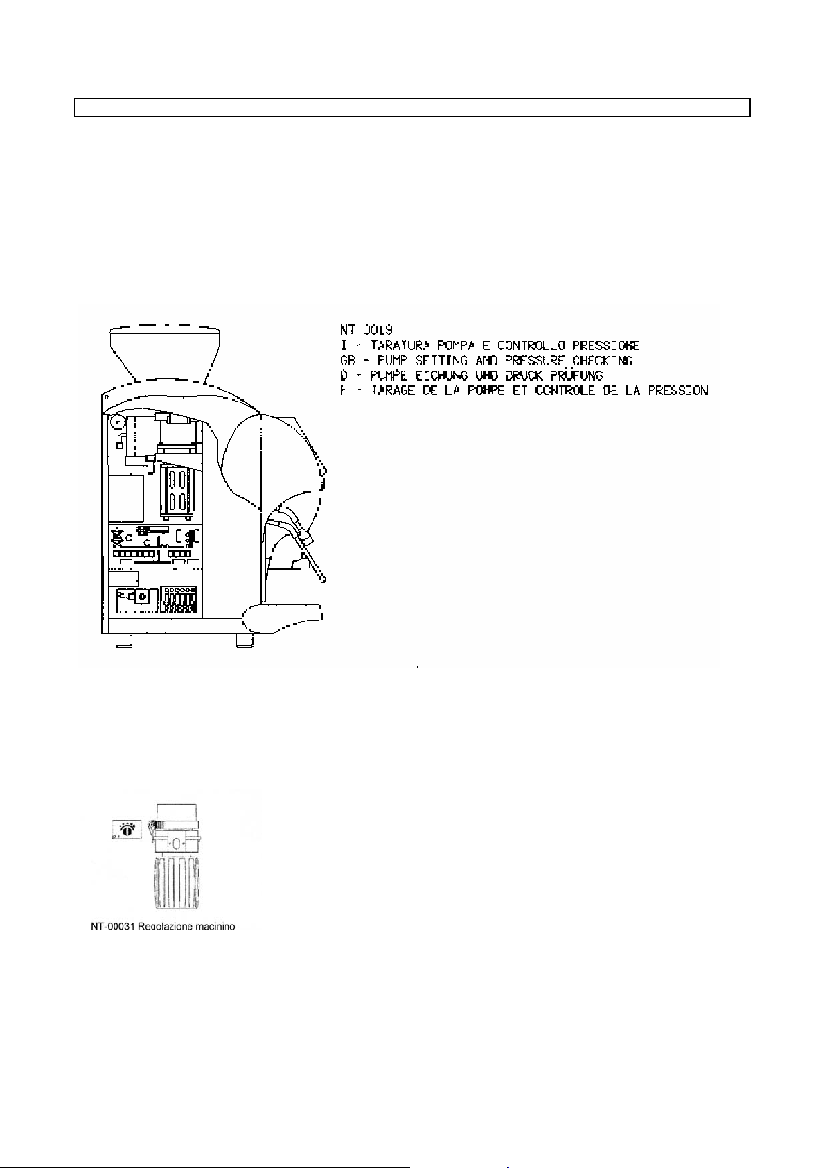
MACHINE COMPONENTS CALIBRATING
1) Calibrating of coffee boiler expansion valve
To calibrate the working pressure (12 bar), of the coffee water boiler (see hydraulic diagram), rotate the rubber sitting
holder connection of the expansion valve clockwise to increase it and anti-clockwise to decrease it.
The working pressure is displayed on the pressure gauge placed on the boiler itself (rear part), when the machine has a
steady stand-by temperature.
2) Coffee dispensing pressure calibrating (pump pressure)
To calibrate the coffee dispensing pressure (8-9 bar max) rotate the pumping body screw, which is reachable from the
machine left side in the rear lower part; rotate it clockwise to increase the pressure, and anti-clockwise to decrease it.
The coffee dispensing pressure is displayed on the gauge placed on the boiler itself, and can be seen from the machine
left side in the rear upper part, when the machine is dispensing coffee.
3) Coffee grinding degree calibrating
To calibrate coffee grinding degree, rotate the grinder adjusting screw (see annex) clockwise to increase it and anticlockwise to decrease it.
4) Calibrating of coffee outlet flow adjustment
To calibrate the dispensing speed and to optimise the quantity of coffee cream, rotate the rubber sitting holder
connection of the coffee outlet regulator (see hydraulic diagram) clockwise to decrease it and anti-clockwise to increase it
Warning:
If you change one of the parameters related to the points 2-3-4, check the other parameters again.
383033GB Pag. 71 November 2003
Page 72

5) Milk frother setting
The machine has a control (RA) which sets the quantity of air needed for whisking milk.
Turn the ring nut clockwise for denser foam (small bubbles), or turn it anticlockwise for more voluminous foam (large
bubbles)
(see diagram)
6) Cold – hot water mix flow adjustment for Tea.
The cold water mix solenoid valve adjustment screw must be adjusted as follows to change the amount of cold water that
is mixed with the hot for making Tea:
- open the machine hatch and remove the black cap on the front.
- turn the adjustment screw on the solenoid valve in a clockwise direction to reduce the amount of cold water.
- turn the adjustment screw on the solenoid valve in an anticlockwise direction to increase the amount of cold water.
See
FIG (a).
383033GB Pag. 72 November 2003
Page 73

BODY DISASSEMBLY PROCEDURE
383033GB Pag. 73 November 2003
Page 74
BOILER DRAINING PROCEDURE
To enter the boiler-draining environment, proceed as follows:
Turn the machine in OFF mode; wait until the boilers have cooled down and the pressure has dropped down to zero.
Dismantle the left side of the machine.
Place the draining pipe of the boiler you want to drain into the drip tray, then remove the tap.
Insert the technician’s smart card into the proper slit.
Press the key N° 12 (gost1), the display shows:
BOILER DRAINING
T1 COFFEE
T2 STEAM
The arrows turned downwards indicate the enabled buttons to choose the type of boiler draining:
Press the key N°1 to start coffee boiler draining (the solenoid valve of the group by-pass will be activated).
Press the key N°2 to start steam boiler draining (the solenoid valve of hot water will be activated).
The display shows:
SOLENOID VALVE
ENABLED
Press the key N1 or N2 to stop the functioning of the enabled solenoid valve.
The display shows:
BOILER DRAINING
COFFEE STEAM
Press the key N° 12 (gost1) to exit the procedure, the display shows:
OFF
It is absolutely necessary to cut off the machine voltage rating.
WARNING:
a) If at the end of the boiler automatic draining procedure the machine voltage rating is not cut off, when the
machine is turned back on, the boiler charge will not be carried out according to the procedure described in
the chapter “Starting up procedure”. The elements can get burned. To avoid this problem, it is absolutely
necessary to preset the machine or disconnect the element power cords.
b) In case of voltage rating lack, automatic draining procedure is not possible.
SPECIAL MAINTENANCE
Special maintenance must be carried out periodically by the Authorised Service Centre in the following way:
Overhaul of the machine every 6 months with special attention to all automatic group components
Replacing the upper and lower piston filters every 10.000 cycles
Replacing the upper piston gaskets every 20.000 cycles or every 6 months
Replacing the lower piston gaskets every 20.000 cycles or every 6 months
Overhaul of the components of the automatic coffee group every 30.000 cycles or every 6 months
Replacing the grinder tools every 300-500 Kg. of coffee or 60.000 cycles. Intervention message for grinder tools
maintenance programmable.
383033GB Pag. 74 November 2003
Page 75

CONTROL UNIT LEGEND
Motor card (see electrical diagram)
Functions of the fuses:
F1 value: 4A type: T input 18Vac
F2 value: 3,15A type: T motor stabilised input
Trimmer functions:
RV1 move this trimmer to raise or lower the threshold for activating the upper piston motor start. By turning
clockwise, the threshold is raised, vice versa, the threshold lowers. Note that the adjustment range of the trimmer is ¾ of
a turn, so make only slight movements on the adjustment screw.
RV2 move this trimmer to raise or lower the threshold for activating the lower piston motor start. By turning clockwise,
the threshold is raised, vice versa, the threshold lowers. Note that the adjustment range of the trimmer is ¾ of a turn, so
make only slight movements on the adjustment screw.
Warning: It is advisable not to vary the calibration of the above trimmer.
Master card (see electric diagram)
Functions of the fuses:
F2 value: 80mA type: T interface I/O output
F3 value: 500mA type: T BARMASTER output
F4 value: 1A type: T CPU card stabilised input
F5 value: 6,3A type: T relays common protection
Functions of the jumpers
Jumper enabled disabled
P1 ----------------------- ----------------------P2 Daytona 1-power Daytona 2-power
P3 ----------------------- -----------------------
383033GB Pag. 75 November 2003
Page 76

Table legend
Y2.5 Hot water solenoid valve
Y2.3 Refill solenoid valve
Y2.7 Coffee group solenoid valve
Y2.2 By – pass solenoid valve
Y2.1 Steam milker solenoid valve
Y1.1 Air milker solenoid valve
Y2.4 Steam nozzle solenoid valve
Y2.6 Mix cold water solenoid valve
Y2.8 rinse milker solenoid valve
RA Air Regulator for milker
PTC Heating element
TRM Trimmer
RD Decaffeinated reed
RF Dregs drawer reed
RS Front door reed
RL Relay X
RRC Coffee boiler element relay
RRV Steam boiler element relay
RS Front door safety relay
SLC Steam boiler level probe
SLS Safety probe
TS Thermostat
STCV Steam boiler temper. probe
STCC Coffee boiler temper. probe
SLC Steam boiler level probe
M1-2 Grinder motor
MP Pump motor
MPS Upper piston motor
MPI Lower piston motor
MES Expeller motor
T Volumetric meter
CN1-2 Connector
FA Anti-jamming filter
FU Fuse
P1..X Jumpers
FIA Filter
VNR NR valve
CC Coffee boiler
CV Steam boiler
MCC Coffee boiler pressure gauge
VS Safety valve
TAN Anti-lime pipe
RCC Coffee boiler element
RCV Steam boiler element
VE Expansion valve
IG Main switch
RSC Cup warmer element
CA Boiler service unit
RRCA Hot water element relay
RUC Coffe outlet adjustment
383033GB Pag. 76 November 2003
Page 77
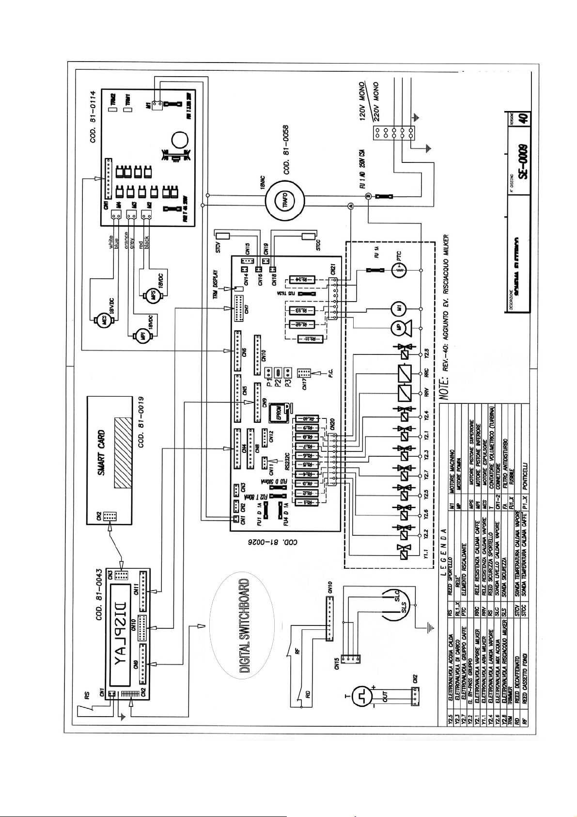
383033GB Pag. 77 November 2003
Page 78

383033GB Pag. 78 November 2003
Page 79
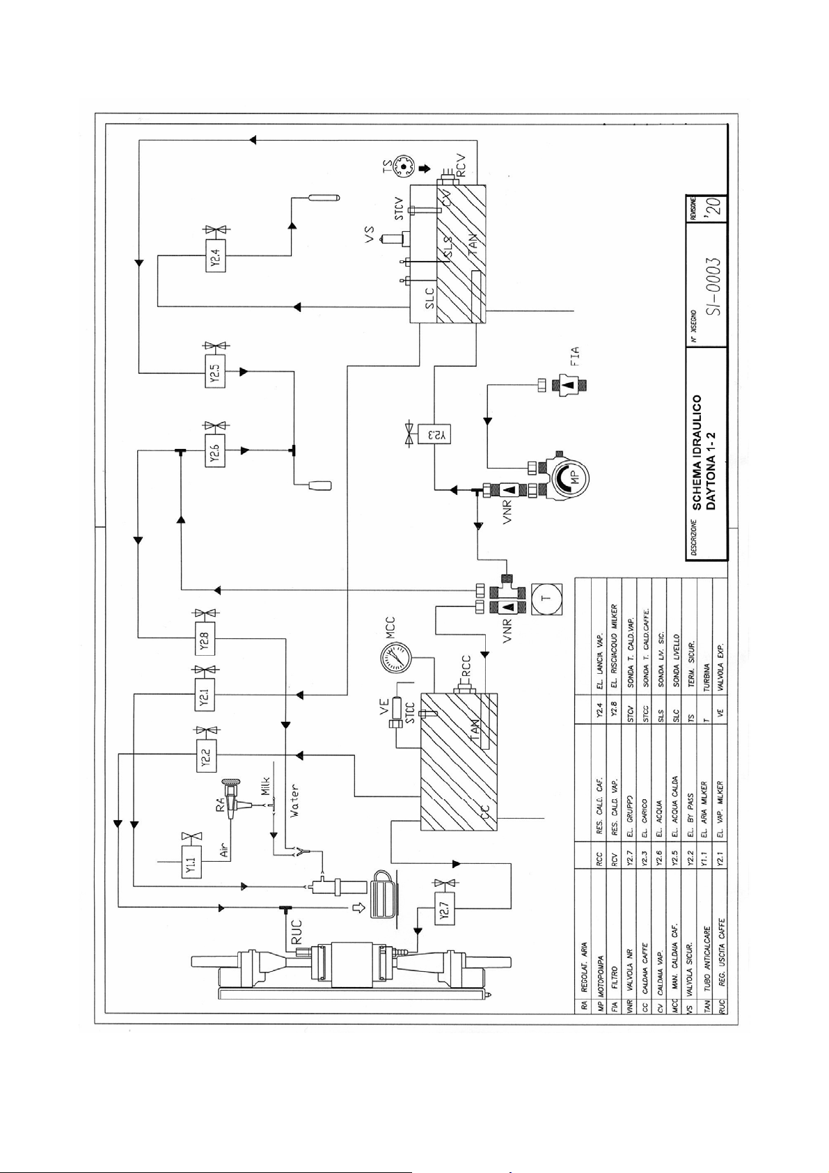
383033GB Pag. 79 November 2003
Page 80

383033GB Pag. 80 November 2003
Page 81

383033GB Pag. 81 November 2003
Page 82

The manufacturer reserves the right to change, without prior notice, the specifications of
the equipment illustrated in this publication; the manufacturer declines all responsibility for
any mistakes due to printing and/or typing errors contained in this publication.
All instructions, drawings, tables and information contained in this publication are reserved
and may not be reproduced entirely or in part or be communicated to a third party without
written authorisation from the manufacturer who holds exclusive rights.
REVISION TABLE
TECNICAL INSTRUCTIONS CODE DATE SOFTWARE MACHINE VERSION
383033GB November 2003 V.3.01
383033GB Pag. 82 November 2003
 Loading...