

Page 1

Embedded &
Industrial Computing
Hardware Platforms for Embedded and Industrial Computing
LEC-3000A
>>
User's Manual
Publication date:2011-09-16
Page 2

TTaTTable of Contentsbeable of Contents
Chapter 1: Introduction 1
System Specication . . . . . . . . . . . . . . . . . . . . . . . . . . . . . . . . . . . . . . . . . . . 1
Package Contents . . . . . . . . . . . . . . . . . . . . . . . . . . . . . . . . . . . . . . . . . . . . . 2
Front Panel Features. . . . . . . . . . . . . . . . . . . . . . . . . . . . . . . . . . . . . . . . . . . . 3
Top and Bottom Panel Features . . . . . . . . . . . . . . . . . . . . . . . . . . . . . . . . . . . . 4
Chapter 2: Hardware Setup 5
Preparing the Hardware Installation. . . . . . . . . . . . . . . . . . . . . . . . . . . . . . . . . . 5
Installing the System Memory . . . . . . . . . . . . . . . . . . . . . . . . . . . . . . . . . . . . . 5
Installing a CompactFlash Card. . . . . . . . . . . . . . . . . . . . . . . . . . . . . . . . . . . . . 5
Connecting Power . . . . . . . . . . . . . . . . . . . . . . . . . . . . . . . . . . . . . . . . . . . . . 6
Chapter 3: Motherboard Information 7
Block Diagram . . . . . . . . . . . . . . . . . . . . . . . . . . . . . . . . . . . . . . . . . . . . . . . 7
Motherboard Layout . . . . . . . . . . . . . . . . . . . . . . . . . . . . . . . . . . . . . . . . . . . 8
Jumper Settings . . . . . . . . . . . . . . . . . . . . . . . . . . . . . . . . . . . . . . . . . . . . . .10
Appendix A: Programming Watchdog Timer 12
Appendix B: Digital Input/Output Control on the GPIO port 17
Appendix E: Driver Installation 22
LAN Adapters Driver Installation. . . . . . . . . . . . . . . . . . . . . . . . . . . . . . . . . . . .22
Windows Operating systems . . . . . . . . . . . . . . . . . . . . . . . . . . . . . . . . . . .22
Linux. . . . . . . . . . . . . . . . . . . . . . . . . . . . . . . . . . . . . . . . . . . . . . . . . . .23
Chipset Platform Driver Installation . . . . . . . . . . . . . . . . . . . . . . . . . . . . . . . . . .23
Windows Operating systems . . . . . . . . . . . . . . . . . . . . . . . . . . . . . . . . . . .23
VGA Driver Installation . . . . . . . . . . . . . . . . . . . . . . . . . . . . . . . . . . . . . . . . . .23
Windows Operating systems . . . . . . . . . . . . . . . . . . . . . . . . . . . . . . . . . . .23
Appendix D: Terms and Conditions 24
Warranty Policy . . . . . . . . . . . . . . . . . . . . . . . . . . . . . . . . . . . . . . . . . . . .24
RMA Service . . . . . . . . . . . . . . . . . . . . . . . . . . . . . . . . . . . . . . . . . . . . . .24
i
Page 3

Chapter 1
Introduction
Chapter 1: Introduction
Thank you for choosing the LEC-3000A. The LEC-3000A is
an embedded automation computer that features high
availability and density of serial communication and
digital I/O ports in a compact frame design (60 mm(W )
x169 mm(H) x126 mm(D)).
The LEC-3000A supports Windows XP Embedded OS and
Windows CE 6.0, which offers a pre-configured image with
optimized on-board device drivers. You can seamlessly
integrate your applications into Windows XP Embedded
system installed on the LEC-3000A and speed up your
system development with this embedded platform that
can provide a rich input and output interfaces to fulfill
automatic control and communicating requirements.
The LEC-3000A also features solid sealed aluminum
extrusion framing. It can provide vibration and dust
resistance coupled with a passive cooling mechanism. It
also provides great protection from EMI and shock.
Here is a summary of the key capabilities of LEC-3000A:
Onboard VIA ULV Eden 1.0 GHz•
Four RS-232/422/485 ports with automatic flow •
control.
Two 10/100/1000 Base-T RJ-45 ports•
Six USB ports (4 external and 2 internal pin headers)•
Built for Windows® CE 5.0 & 6.0, Windows XP •
Embedded, and Linux ready solution
Onboard isolated digital inputs and outputs•
Fanless and no internal cabling design•
Compliant to ACPI 3.0 and PCI Bus Power Management •
1.1
Please refer to the following chart below for a detailed
description of the system’s specifications.
System Specification
FEATURE
Platform
Memory
Storage
Networking
I/O
Hardware
Monitor
OS Supported
Environmental
Parameters
DESCRIPTION
Form Factor DIN-Mount
Processor VIA ULV Eden 1.0 GHz
Chipset VIA VX800
BIOS AMI Flash BIOS
Memory IC On
Board
Memory Socket 1 x SODIMM (up to 2GB per slot)
Max Memory 2GB (1 x 2GB Module)
Compact Flash
Controller (Interface)
COM Ports
USB 2.0 4 x External, (2 x Internal)
VGA 1
LAN 2 x RJ45 GbE
DIDO 4 x DI, 4 x DO
Internal CF 1
Controller
Watchdog timer Yes (1~255 level)
Operating Temperature
(With Industrial
Components:
CF, Memory)
Operating Temperature
(With Commercial
Components)
Extended Operating Temperature
Tested
LEC-3000A
No
1 x CF Socket Type I/II (internal/
external options available)
Realtek RTL8111D x 2
4 x RS-232/422/485
(Hardware Auto Flow Control)
Fintek 81865F integrated hardware monitor
Embedded Windows XP/Linux
kernel 2.4.16 or above/WindowsXP 32 bit
-20°~55°C / 14°~131°F
-5°C~45°C / 23°~113°F
N/A
Embedded and Industrial Computing
Dimensions
Power
Compliance
W x H x D (mm) 60 x 169 x 126 mm
Weight 1.4Kg/3.1lbs
DC Power 12V ~ 36V DC in
Adapter 60W Adapter
CE, FCC, RoHS
1
Page 4

Chapter 1
Package Contents
Your package contains the following items:
LEC-3000A Embedded System •
Din-Rail Mounting Kit •
Drivers and User’s Manual CD •
Introduction
Embedded and Industrial Computing
2
Page 5

Chapter 1
Front Panel Features
F1 VGA Port
Using suitable DB-15 cable, you can connect an appropriate device such as a monitor.
F2 Four USB 2.0 type A ports
It connects to any USB devices, for example, a flash drive.
Two 10/100/1000Mbps LAN ports (LAN1:left, LAN2:right)
Using suitable RJ-45 cable, you can connect LEC-3000A System to a computer, or to any other piece of equipment
that has an Ethernet connection such as a hub or a switch.
Introduction
F1
F2
1 2 3 4 5 6 7 8 9 10
11 12 13 14 1516 17 18 19 20
F3
F4
F5
F3 20-pin Phoenix Contact Terminal Block
This connector can be connected for 4 Com ports (COM4: Pin 1~5, Com3: Pin 6~10, Com2: Pin11~15, Com1: Pin
16~20) with serial port type of RS-232, RS-422 or RS-485; it supports dip switch selection of RS-232, RS-422 and
485. The following table lists the pin assignments.
Pin NO.
Port Type
RS-232 Ground
RS-422 Ground
RS-485 Ground
Pin NO.
Port Type
RS-232 GND CTS2# SOUT2 SIN2 RTS2# GND CTS1# SOUT1 SIN1 RTS1#
RS-422 GND RX- RX+ TX+ TX- GND RX- RX+ TX+ TXRS-485 GND NC NC DATA+ DATA- GND NC NC DATA+ DATA-
F4 Serial Port Status LED
The left two columns are LED indicators of Digital Output/Input.
The right two columns are LED indicators of Tx (Data transmitting) and RX (Data receiving) for Serial Port Status.
DO-Pin 1 DI-Pin 1 RX-Com 1 TX-Com 1
DO-Pin 2 DI-Pin 2 RX-Com 2 TX-Com 2
DO-Pin 3 DI-Pin 3 RX-Com 3 TX-Com 3
DO-Pin 4 DI-Pin 4 RX-Com 4 TX-Com 4
Pin 1 Pin 2 Pin 3 Pin 4 Pin 5 Pin 6 PIN7 PIN 8 PIN 9 Pin10
CTS4# SOUT4 SIN4 RTS4# GND CTS3# SOUT3 SIN3 RTS3#
(GND)
RX- RX+ TX+ TX- GND RX- RX+ TX+ TX-
(GND)
NC NC DATA+ DATA- GND NC NC DATA+ DATA-
(GND)
Pin 11 Pin 12 Pin 13 Pin 14 Pin 15 Pin 16 Pin 17 Pin 18 Pin 19 Pin 20
F5 Power/Status/HDD LED
Power Green indicates Power-on, where as Off indicates Power-off status.
Run A programmable dual green/orange LEDs which can be used for indicating system
status.
Hard Disk Yellow indicates that HDD is present, whereas Off indicates HDD is not present.
Embedded and Industrial Computing
3
Page 6
Chapter 1
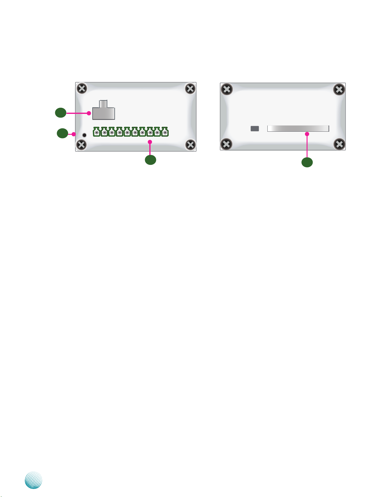
Top and Bottom Panel Features
- +
R2
Introduction
R1
1 2 3 4 5 6 7 8 9 10
R3
R1 Reset Switch: A hardware reset switch
Use a pointed object to press it 5 seconds then release it to reset the system
without turning off the power.
R2 Power Socket
Power supply through 1x2-pin Phoenix Contact with 12~36V dual power
source.
R3 Digital Input/Output port:
The digital input/output (DIO) peripheral is provided through 10-pin terminal
block connector.
Pin 2 to 5: Digital Inputs.
Pin 7 to10: Digital Output.
R4 CompactFlash Connector
One Type I / Type II CompactFlash card slot is provided by the system.
R4
Embedded and Industrial Computing
4
Page 7

Chapter 2
Introduction
Chapter 2: Hardware Setup
Preparing the Hardware Installation
To access some components and perform certain service
procedures, you must perform the following procedures
first.
WARNING: To reduce the risk of personal injury,
electric shock, or damage to the equipment,
remove the power cord to remove power from the
server. The front panel Power On/Standby button
does not completely shut off system power.
Portions of the power supply and some internal
circuitry remain active until AC power is removed.
Unpower the LEC-3000A and remove the power cord.1.
Unscrew the 4 threaded screws from the top cover of 2.
the LEC-3000A System.
Slide the cover backwards and open the cover 3.
upwards.
Note:
SO-DIMMs installed should meet the required 1.
speed which is 667 MHz. Do not install SO-DIMM
supporting different speeds.
The motherboards can support up to 2 GB 2.
memory capacity in maximum.
Installing a CompactFlash Card
LEC-3000A provides one CompactFlash slot(CF1). Follow
the procedures bellow for installing a CompactFlash card.
Unscrew the thumbscrews on the CF slot to take out 1.
the front cover.
Align CompactFlash and the card slot with the arrow 2.
on the CompactFlash pointing toward the connector.
Insert the CompactFlash into the connector.3.
Close the cover and fasten it with thumb screws to 4.
the slot.
1
Installing the System Memory
The motherboard supports DDR2 memory that features
data transfer rates of 667 MHz to meet the higher
bandwidth requirements of the latest operating system
and Internet applications. It comes with one Double Data
Rate(DDR2) Small Outline Dual Inline Memory Module
(SO-DIMM) socket.
Align the memory module’s cutout with the SO-DIMM 1.
socket’s notch.
Install the SO-DIMM.2.
Notch
Cutout
Embedded and Industrial Computing
2
3
4
5
Page 8

Chapter 2
Connecting Power
Connect the LEC-3000A to a 12~36 VDC power source.
The power source comes from the AC/DC Adapter
through a Phoenix contact. This power socket is specially
designed to guard against fault in power contact, i.e.,
the reverse of the electrical polarity will not damage the
system.
-
+
Introduction
Embedded and Industrial Computing
6
Page 9

Chapter 3
VIA C7®-M
processor
12 watts at 1.5GHz
VX800
(33X33mm)
~5W
LPC
DDR2 667 MHz
800/400MHz FSB
Compact Flash
2x USB
PIN header
4x USB
connectors
USB 2.0
SATAII
1x SATAII Port
Up to 2GB Maximum
Fintek
81865F
4 COM ports
Flash
BIOS
IDE
VX800 integrated graphic
engine
VGA connector
Watchdog
LEB-3000A
DI/DO
Hardware Monitor
2x GbE RJ-45
Connectors w/ LED
2x PCI-E
RealTek
RTL8111
RealTek
RTL8111
VIA DriveStation
PWM Module
DC +12V
Output
DC
+12~36V
DC +12V
Input
LEK-DC01
DC/DC Converter Board
Chapter 3: Motherboard Information
Block Diagram
The block diagram depicts the relationships among the
interfaces or modules on the motherboard. Please refer
to the following figure for your motherboard’s layout
design.
Motherboard Information
Embedded and Industrial Computing
7
Page 10

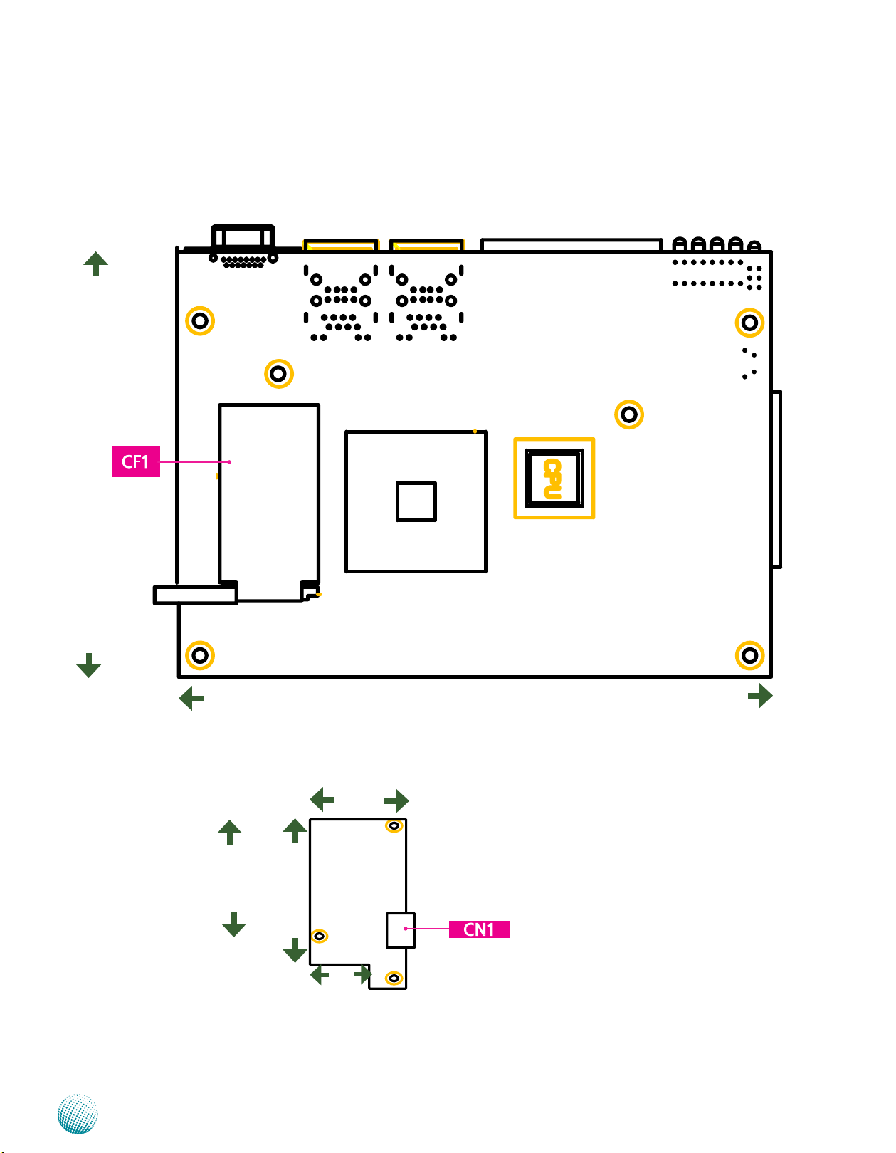
Chapter 3
Motherboard Layout
The motherboard layout shows the connectors and
jumpers on the board. Refer to the following picture
as a reference of the pin assignments and the internal
connectors.
Motherboard Information
Embedded and Industrial Computing
8
Page 11
Chapter 3
Rear Side of the Main Board
114
Motherboard Information
DC/DC converter board
89.27
Embedded and Industrial Computing
159
41.6
99
25.6
Board dimension unit in mm
9
Page 12

Chapter 3
Motherboard Information
Jumper Settings
SATA1: The system supports one SATA II drive
Pin No. Function
1
2
3
4
5
6
7
SO-DIMM1: The SO-DIMM socket is used to connect the
DDR2 667 (200 pin) memory. The system can suport up to
2 GB in maximum.
ATX12V1: The system is designed to operate with a single
DC input with voltage range from +12 to 36V. And it is
supplied through the Phoenix Contact. This connector is
provided for the main board to recevie power from the
input source.
1 GND
2 TX+
3 TX4 GND
5 RX6 RX+
7 GND
CN2: This connector provides 4 digital inputs and 4 digital
outputs. The connector type of LEC-3000A is plug-in screw
terminal block that enables you to connect to field I/O
devices directly without additional accessories.
12 3 4 5 6 7 8 9 10
Pin No. 1 2 3 4 5
Function GND Input0 Input1 Input2 Input3
Pn No. 6 7 8 9 10
Function GND Output0 Output1 Output2 Output3
Isolated Digital Inputs Requirements
Input Voltage:
Logic 0: 0 ~ 2V DC
Logic 1: 2~5V DC
Function Pin No.
NC 1
GND 3
GND 5
GND 7
GND 9
1 3 5 7 9
2 4 6 8 10
Pin No. Function
2 VCC12
4 VCC12
6 VCC12
8 VCC12
10 VCC12
Embedded and Industrial Computing
10
Page 13

Chapter 3
Motherboard Information
SW2/SW3/SW4/SW5: These switches — SW2, SW3, SW4
and SW5 — are used to adjust the serial port type for
COM1, COM2, COM3, and COM4 respectively. Use the
table below as the switch adjustment information for
COM1 through COM4.
12 3 4
ON
OFF
COM Port No.
Port Type
RS-232 Switch 2:
RS-422 Switch 2:
RS-485 Switch 2:
COM 1 COM 2 COM 3 COM 4
1 ON
2 OFF
3 OFF
4 OFF
1 OFF
2 ON
3 ON
4 OFF
1 OFF
2 ON
3 OFF
4 ON
Switch 3:
1 ON
2 OFF
3 OFF
4 OFF
Switch 3:
1 OFF
2 ON
3 ON
4 OFF
Switch 3:
1 OFF
2 ON
3 OFF
4 ON
Switch 4:
1 ON
2 OFF
3 OFF
4 OFF
Switch 4:
1 OFF
2 ON
3 ON
4 OFF
Switch 4:
1 OFF
2 ON
3 OFF
4 ON
Switch 5:
1 ON
2 OFF
3 OFF
4 OFF
Switch 5:
1 OFF
2 ON
3 ON
4 OFF
Switch 5:
1 OFF
2 ON
3 OFF
4 ON
SW6/SW7/SW8/SW9: These switches — SW6, SW7,
SW8 and SW9 — are used to enable or disable the
signal termination for COM1, COM2, COM3, and
COM4 respectively. Use the table below for the switch
adjustment information for COM1 through COM4. We
strongly recommend that you disable termination when
the port is configured as RS-232 and enable it when the
port is configured as RS-485/RS-422.
ON
OFF
COM
Port No.
Port Type
RS-232 Switch 2:
RS-422 Switch 2:
RS-485 Switch 2:
Termination
(Enable/disable)
Embedded and Industrial Computing
COM 1 COM 2 COM 3 COM 4
1 ON
2 OFF
3 OFF
4 OFF
1 OFF
2 ON
3 ON
4 OFF
1 OFF
2 ON
3 OFF
4 ON
Switch 6:
Enable ON
Disable: OFF
Switch 3:
1 ON
2 OFF
3 OFF
4 OFF
Switch 3:
1 OFF
2 ON
3 ON
4 OFF
Switch 3:
1 OFF
2 ON
3 OFF
4 ON
Switch 7:
Enable ON
Disable: OFF
Switch 4:
1 ON
2 OFF
3 OFF
4 OFF
Switch 4:
1 OFF
2 ON
3 ON
4 OFF
Switch 4:
1 OFF
2 ON
3 OFF
4 ON
Switch 8:
Enable ON
Disable: OFF
Switch 5:
Switch 5:
Switch 5:
Switch 9:
Enable ON
Disable: OFF
1 ON
2 OFF
3 OFF
4 OFF
1 OFF
2 ON
3 ON
4 OFF
1 OFF
2 ON
3 OFF
4 ON
CMOS1: This jumper provides a means to return the BIOS
settings to its default state automatically on power-up.
3 2 1
Pin No. Function
Short 1-2 Normal (Default)
2-3 Clear CMOS
SPI-ROM(J1): Using the appropriate cable to connect this
10-pin ISP in header connector, the user can update the
SPI Flash soldered on board
Function Pin No.
SPI_HOLD_N 1
SPI_CS0_N 3
SPI_MISO 5
RSVD 7
GND 9
1
3
5
7
9
Pin No. Function
2
4
6
8
10
2 RSVD
4 +3.3V
6 RSVD
8 SPI_CLK
10 SPI_MOSI
CN1: Connector CN1 provides access to the COM1
through COM4 serial port’s data transmission when the
port is configured for either RS-422/RS-485 or RS-232 serial
protocol. The signals present on each of the connector’s
pins for these three modes can be referenced in Front
Panel Features, Chapter 1 Introduction. The COM ports'
serial protocol mode is configured using the following
dip switches: SW2, SW3, SW4, and SW5. In addition, when
used as in RS-485 mode, the system can automatically
detect the direction of incoming data and switches its
transmission direction accordingly - the automatic data
flow control in RS-485. Hence, no handshaking signal (RTS
signal) is necessary. This allows you to conveniently build
an RS-485 network with just two wires. More significantly,
application software previously written for half duplex
RS-232 environments can be maintained without
modification.
USBF1: Dual USB Interface Connector (USB No.4 and
No.5): It is used for connecting the USB module cable.
It complies with USB2.0 and support up to 480 Mbps
connection speed.
Pin Name Pin No.
USB_VCC4 1
USBD4N 5
USBD4P 7
GND 9
1
3
3
5
7
9
Pin No. Pin Name
2
4
6
8
10
2 GND
4 USBD5P
6 USBD5N
8
10
USB_VCC5
CF1: A Compact Flash Connector. It is used for connecting
a Compact Flash card to serve as your system's storage.
CN1(on DC/DC converter board): A power socket for a
power supply through Phoenix Contact.
Pin No. 1 2
12
Function Ground DC=In
11
Page 14

Appendix A
Programming Watchdog Timer
Appendix A: Programming Watchdog Timer
A watchdog timer is a piece of hardware that can be
used to automatically detect system anomalies and reset
the processor in case there are any problems. Generally
speaking, a watchdog timer is based on a counter that
counts down from an initial value to zero. The software
selects the counter’s initial value and periodically restarts
it. Should the counter reach zero before the software
restarts it, the software is presumed to be malfunctioning
and the processor’s reset signal is asserted. Thus, the
processor will be restarted as if a human operator had
cycled the power.
For sample watchdog code, see Watch dog and DIO folder
in the Driver and Manual CD
Click Next to proceed5.
Answer “Yes” to the question and select Next to 6.
proceed.
Driver Installation
Before you could access or control the operation of the
watchdog and Digital I/O functions, install the the L_IO
driver which is the library and driver needed for Lanner
General Purpose Input/Output interface or functions.
To install the L_IO driver:
Restart the computer, and then log on with 1.
Administrator privilege.
Insert the Drivers and User’s Manual CD to the USB-2.
optical drive.
Browse the contents of the support CD to locate the 3.
file LIO.rar under the \Watch dog and DIO\LIO folder
and unzip the file.
From the control panel, click the ADD Hardware 4.
program
Select Add a new hardware device.7.
Embedded and Industrial Computing
12
Page 15

Appendix A
Programming Watchdog Timer
Choose to select the hardware Manually8.
Choose Show all device and click Next.9.
Click HaveDisk to locate the L_IO.inf file11.
Select the L_IO.inf12.
Click HaveDisk to locate the L_IO.inf file10.
Embedded and Industrial Computing
Select OK to confirm with the installation13.
13
Page 16

Appendix A
Programming Watchdog Timer
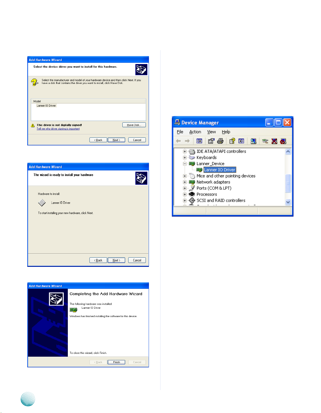
Select the Lanner IO driver and click Next.14.
Click Next15.
To verify the GPIO driver installation, do the following
steps:
Right-click on the My Computer icon, and then select 1.
Properties form the menu.
Click the Hardware tab, then click the Device Manager 2.
button.
Click the + sign next to the Lanner_Device, then the 3.
Lanner IO Driver should be listed.
Click 16. Complete to close the installation program.
Embedded and Industrial Computing
14
Page 17

Appendix A
Programming Watchdog Timer
Watch Dog sample code:
// LEC3000_Test.cpp : Defines the entry point for the console
application.
//
#include “Windows.h”
#include “stdio.h”
#include “F81865.h”
#define PARAMETER_HELP “Test 1 ==> Test DIO \nTest 2 ==>
Test LED \nTest 3 ==> Enable WatchDog \nTest 4 ==> Disable
WatchDog\n”
#define RETMSG(a,b) {printf (b) ; return a;}
int main(int argc, char* argv[])
{
try
{
int i = 0 ;
}
for (i = 0 ; i < 4 ; i++)
{
printf (“Set
DIO#%d=0\n”, i) ;
Write_DIO (i, 0) ;
Sleep (1) ;
printf (“Read DIO=”) ;
for (int j = 0 ; j < 4 ; j++)
printf (“%d”,
Read_DIO (j) ) ;
printf (“\n”) ;
Sleep (500) ;
}
}
else if (argv[1][0] == ‘2’)
{
printf (“LED Red\n”) ;
if (argc != 2)
RETMSG (-1, PARAMETER_HELP) ;
if (argv[1][0] == ‘1’)
{
for (i = 0 ; i < 4 ; i++)
{
printf (“Set
DIO#%d=1\n”, i) ;
Write_DIO (i, 1) ;
Sleep (1) ;
printf (“Read DIO=”) ;
for (int j = 0 ; j < 4 ; j++)
printf (“%d”,
Read_DIO (j) ) ;
printf (“\n”) ;
Sleep (500) ;
Run_LED (0, 1) ;
Run_LED (1, 0) ;
Sleep (1000) ;
printf (“LED Green\n”) ;
Run_LED (0, 0) ;
Run_LED (1, 1) ;
Sleep (1000) ;
printf (“LED Amber\n”) ;
for (i = 0 ; i < 33 ; i++)
{
Run_LED (0, 1) ;
Run_LED (1, 0) ;
Sleep (1) ;
Run_LED (0, 0) ;
Run_LED (1, 1) ;
Sleep (1) ;
}
Embedded and Industrial Computing
15
Page 18

Appendix A
Run_LED (0, 0) ;
Run_LED (1, 0) ;
}
else if (argv[1][0] == ‘3’)
{
WatchDog_Enable (10) ;
while (1)
{
int nLeft = WatchDog_
GetLeft () ;
printf (“WatchDog left
%d seconds \r”, nLeft) ;
} ;
Programming Watchdog Timer
}
else if (argv[1][0] == ‘4’)
{
WatchDog_Enable (0) ;
printf (“Watchdog disabled\n”) ;
}
else
RETMSG (-1, “Wrong
argement\n”) ;
return 0 ;
} catch (char *str)
{
printf (“\n”) ;
printf (str) ;
}
catch (...)
{
printf (“\nUnknown Exception\n”) ;
}
}
Embedded and Industrial Computing
16
Page 19

Appendix B
Digital Input/Output Control
Appendix B: Digital Input/Output Control on the GPIO port
The Digitanl I/O on the rear panel is designed to provide
the input and output operations for the system. For
sample DIO code, see Watch dog and DIO in the Driver and
Manual CD.
Driver Installation
Before you could access or control the operation of the
watchdog and Digital I/O functions, install the the L_IO
driver which is the library and driver needed for Lanner
General Purpose Input/Output interface or functions.
To install the L_IO driver:
Restart the computer, and then log on with 1.
Administrator privilege.
Insert the Drivers and User’s Manual CD to the USB-2.
optical drive.
Click Next to proceed5.
Answer “Yes” to the question and select Next to 6.
proceed.
Browse the contents of the support CD to locate the 3.
file LIO.rar under the \Watch dog and DIO\LIO folder
and unzip the file.
From the control panel, click the ADD Hardware 4.
program
Select Add a new hardware device.7.
Embedded and Industrial Computing
17
Page 20

Appendix B
Digital Input/Output Control
Choose to select the hardware Manually8.
Choose Show all device and click Next.9.
Click HaveDisk to locate the L_IO.inf file11.
Select the L_IO.inf12.
Click HaveDisk to locate the L_IO.inf file10.
Embedded and Industrial Computing
Select OK to confirm with the installation13.
18
Page 21
Appendix B
Digital Input/Output Control
Select the Lanner IO driver and click Next.14.
Click Next15.
To verify the GPIO driver installation, do the following
steps:
Right-click on the My Computer icon, and then select 1.
Properties form the menu.
Click the Hardware tab, then click the Device Manager 2.
button.
Click the + sign next to the Lanner_Device, then the 3.
Lanner IO Driver should be listed.
Click 16. Complete to close the installation program.
Embedded and Industrial Computing
19
Page 22

Appendix B
Digital Input/Output Control
A DIO sample code:
// LEC3000_Test.cpp : Defines the entry point for the
console application.
//
#include “Windows.h”
#include “stdio.h”
#include “F81865.h”
#define PARAMETER_HELP “Test 1 ==> Test DIO \nTest 2
==> Test LED \nTest 3 ==> Enable WatchDog \nTest 4 ==>
Disable WatchDog\n”
#define RETMSG(a,b) {printf (b) ; return a;}
int main(int argc, char* argv[])
{
try
{
int i = 0 ;
Sleep (500) ;
}
for (i = 0 ; i < 4 ; i++)
{
printf (“Set
DIO#%d=0\n”, i) ;
Write_DIO (i, 0) ;
Sleep (1) ;
printf (“Read DIO=”) ;
for (int j = 0 ; j < 4 ;
j++)
printf (“%d”,
Read_DIO (j) ) ;
printf (“\n”) ;
Sleep (500) ;
}
}
else if (argv[1][0] == ‘2’)
if (argc != 2)
RETMSG (-1, PARAMETER_HELP)
;
if (argv[1][0] == ‘1’)
{
for (i = 0 ; i < 4 ; i++)
{
printf (“Set
DIO#%d=1\n”, i) ;
Write_DIO (i, 1) ;
Sleep (1) ;
printf (“Read DIO=”) ;
for (int j = 0 ; j < 4 ;
j++)
printf (“%d”,
Read_DIO (j) ) ;
{
printf (“LED Red\n”) ;
Run_LED (0, 1) ;
Run_LED (1, 0) ;
Sleep (1000) ;
printf (“LED Green\n”) ;
Run_LED (0, 0) ;
Run_LED (1, 1) ;
Sleep (1000) ;
printf (“LED Amber\n”) ;
for (i = 0 ; i < 33 ; i++)
{
Run_LED (0, 1) ;
Run_LED (1, 0) ;
Sleep (1) ;
Run_LED (0, 0) ;
printf (“\n”) ;
Embedded and Industrial Computing
Run_LED (1, 1) ;
20
Page 23

Appendix B
Sleep (1) ;
}
Run_LED (0, 0) ;
Run_LED (1, 0) ;
}
else if (argv[1][0] == ‘3’)
{
WatchDog_Enable (10) ;
while (1)
{
int nLeft = WatchDog_
GetLeft () ;
Digital Input/Output Control
printf (“WatchDog left
%d seconds \r”, nLeft) ;
} ;
}
else if (argv[1][0] == ‘4’)
{
WatchDog_Enable (0) ;
printf (“Watchdog disabled\n”)
;
}
else
RETMSG (-1, “Wrong
argement\n”) ;
return 0 ;
} catch (char *str)
{
printf (“\n”) ;
printf (str) ;
}
catch (...)
{
printf (“\nUnknown Exception\n”) ;
}
}
Embedded and Industrial Computing
21
Page 24

Appendix E
Driver Installation
Appendix E: Driver Installation
LAN Adapters Driver Installation
This section provides the instructions on how to install
Realtek® Gigabit LAN adapter drivers.
Windows Operating systems
To install the Realtek® Gigabit LAN controller driver on a
Windows Operating System:
Restart the computer, and then log on with 1.
Administrator privileges.
Insert the Drivers and User’s Manual CD to the USB-2.
Optical drive.
Browse the contents of the Drivers and User’s Manual 3.
CD to locate the file SETUP.EXE from the \Driver\
RTL8111_Driver folder. Double-click the SETUP.EXE
The4. REALTEK GbE & FE Ethernet PCI-E NIC Driver
installer program starts. Click Next to begin the
installation.
Please wait while the installation is in progress.6.
Click7. Finish to close the installation program.
When the 5. Ready to Install the Program window
appears, click Install to proceed .
Network Application Platforms
22
Page 25

Appendix E
Driver Installation
Linux
Follow these instructions to install the Realtek® LAN
controller base driver for the Red Hat® and Linux operating
system.
Insert the Drivers and User’s Manual CD to the USB-1.
Optical drive and mount the optional drive in the
Linux platform.
Copy the archive driver in BZ2 file from the Drivers and 2.
User’s Manual CD to the directory of your local hard
disk. The Realtek® LAN driver for Linux OS is located in
the following directory:
\Driver\RTL8111_Driver\LINUX. The name format of
driver file is “r8168-<Version>.tar.bz2”.
Untar/unzip the archive file:3.
tar xvfj <driver-file-in>.tar.bz2
Compile the driver module by typing the following 4.
command:
make install
The binary will be installed as:5.
/lib/modules/<kernel_version>/kernel/drivers/net/
The install locations listed above are the default
locations. They might not be correct for certain Linux
distributions.
Chipset Platform Driver Installation
The VIA Hyperion Pro Driver features four drivers to help
increase the stability and performance of the system with
VIA chipsets as well as tools which are useful for advanced
configurations. These drivers include IDE Falcon Storage
Device driver, AGP Driver, RAID Driver and Raid Tools, and
so on.
Windows Operating systems
Restart the computer, and then log on with 1.
Administrator privileges.
Insert the Drivers and User’s Manual CD to the USB-2.
Optical drive.
Browse the contents of the Drivers and User’s Manual 3.
CD under the directory: \Driver\VIA_HyperionPro_
Driver.
Execute the installer program, “SETUP.exe” by double-4.
clicking the icon.
Note: For drivers installing on linux based operating
systems such as Ubuntu and SuSE Linux , visit Via’s
download page at http://linux.via.com.tw/support/
downloadFiles.action
Assign an IP address to the interface by entering the 6.
following, where <x> is the interface number:
ifconfig eth<x> <IP_address>
Verify that the interface works. Enter the following, 7.
where <IP_address> is the IP address for another
machine on the same subnet as the interface that is
being tested:
ping <IP_address>
Note: For LAN drivers installing on other operating
systems, visit Realtek’s download page at
http://www.realtek.com.tw/Downloads/
downloadsView.aspx?Langid=1&PNid=13&PFid=5
&Level=5&Conn=4&DownTypeID=3&GetDown=fa
lse.
VGA Driver Installation
This section provides the instructions on how to install
VGA adapter drivers.
Windows Operating systems
Restart the computer, and then log on with 1.
Administrator privileges.
Insert the Drivers and User’s Manual CD to the USB-2.
Optical drive.
Browse the contents of the Drivers and User’s Manual 3.
CD under the directory: \ Driver\VIA_VGA_Driver_for_
XP_2K.
Execute the installer program, “SETUP.exe” by double-4.
clicking the icon.
Network Application Platforms
23
Page 26

Appendix D
Terms and Conditions
Appendix D: Terms and Conditions
Warranty Policy
All products are under warranty against defects in 1.
materials and workmanship for a period of one year
from the date of purchase.
The buyer will bear the return freight charges for 2.
goods returned for repair within the warranty period;
whereas the manufacturer will bear the after service
freight charges for goods returned to the user.
The buyer will pay for repair (for replaced components 3.
plus service time) and transportation charges (both
ways) for items after the expiration of the warranty
period.
If the RMA Service Request Form does not meet the 4.
stated requirement as listed on “RMA Service,” RMA
goods will be returned at customer’s expense.
The following conditions are excluded from this 5.
warranty:
RMA Service
Requesting a RMA#
To obtain a RMA number, simply fill out and fax the 6.
“RMA Request Form” to your supplier.
The customer is required to fill out the problem code 7.
as listed. If your problem is not among the codes listed,
please write the symptom description in the remarks
box.
Ship the defective unit(s) on freight prepaid terms. 8.
Use the original packing materials when possible.
Mark the RMA# clearly on the box. 9.
Note: Customer is responsible for shipping
damage(s) resulting from inadequate/loose
packing of the defective unit(s). All RMA# are valid
for 30 days only; RMA goods received after the
effective RMA# period will be rejected.
Improper or inadequate maintenance by the customer
Unauthorized modification, misuse, or reversed
engineering of the product Operation outside of the
environmental specifications for the product.
Embedded and Industrial Computing
24
Page 27

Appendix D
RMA Service Request Form
When requesting RMA service, please fill out the following form. Without
this form enclosed, your RMA cannot be processed.
RMA No:
Reasons to Return: Ŀ Repair(Please include failure details)
Ŀ Testing Purpose
Company: Contact Person:
Phone No. Purchased Date:
Fax No.: Applied Date:
Return Shipping Address:
Shipping by: Ŀ Air Freight Ŀ Sea Ŀ Express ___
Ŀ Others:________________
Item Model Name Serial Number Configuration
Item Problem Code Failure Status
*Problem Code:
01:D.O.A.
02: Second Time
R.M.A.
03: CMOS Data Lost
04: FDC Fail
05: HDC Fail
06: Bad Slot
07: BIOS Problem
08: Keyboard Controller Fail
09: Cache RMA Problem
10: Memory Socket Bad
11: Hang Up Software
12: Out Look Damage
13: SCSI
14: LPT Port
15: PS2
16: LAN
17: COM Port
18: Watchdog Timer
19: DIO
20: Buzzer
21: Shut Down
22: Panel Fail
23: CRT Fail
24: Others (Pls specify)
Request Party
Confirmed By Supplier
Authorized Signature / Date Authorized Signature / Date
Terms and Conditions
Embedded and Industrial Computing
25
 Loading...