


Land Rover Range Rover Sport 2005, Range Rover Sport 2006, Range Rover Sport 2007, Range Rover Sport 2008, Range Rover Sport 2009 User Manual
http://www.landrovertechinfo.com/extlrprod/frmviewit.jsp?szFrom=doc&iDocCode=276785 |
07/16/2006 12:59 PM |
Published: Feb 17, 2005
Standard Workshop Practices
Vehicle in Workshop
When working on a vehicle in the workshop always make sure that:
Where practicable, the parking brake is applied and the wheels are securely chocked to prevent the vehicle moving forwards or backwards.
Whenever possible, the ignition key is removed before any work is carried out on the vehicle.
If the engine is to be run, there is adequate ventilation, or an extraction hose is used to remove exhaust fumes. There is adequate room to raise the vehicle and remove the wheels, if necessary.
Fender covers are always fitted if any work is to be carried out in the engine compartment.
Where practicable, the battery is disconnected if working on the engine, underneath the vehicle, or if the vehicle is raised.
 CAUTION: Prior to disconnecting the battery, refer to the Electrical Section of this manual - Battery disconnection/connection.
 CAUTION: When electric arc welding on a vehicle, always disconnect the generator wiring to prevent the possibility of a surge of current causing damage to the internal components of the generator.
If using welding equipment on the vehicle, a suitable fire extinguisher is readily available.
Towing the Vehicle
 WARNING: When towing is necessary, reference must be made to the Jacking, Lifting and Towing Section of this Manual. When the vehicle is being towed the ignition switch must be in position II (steering lock released and warning lights illuminated). Only then will the steering, turn signal lamps, horn and stop lamps be operational. Failure to follow these instructions may result in personal injury. It must be noted that with the engine not running, the power steering and brake booster will be inoperative therefore, greater effort will be needed to steer the vehicle and apply the brakes.
Battery - General
 CAUTION: Prior to carrying out any procedures which involve disconnecting/ or connecting the battery, refer to the Electrical Section of this manual - Battery disconnection/connection.
 CAUTION: A discharged battery condition may have been caused by an electrical short circuit. If this condition exists there will be an apparently live circuit on the vehicle even when all normal circuits are switched off. This can cause arcing when the jumper cables are connected.
http://www.landrovertechinfo.com/extlrprod/frmviewit.jsp?szFrom=doc&iDocCode=276785 |
Page 1 of 25 |

http://www.landrovertechinfo.com/extlrprod/frmviewit.jsp?szFrom=doc&iDocCode=276785 |
07/16/2006 12:59 PM |
 CAUTION: While it is not recommended that the vehicle is jump started, it is recognized that this may occasionally be the only practical way to mobilize a vehicle. Prior to attempting a jump start, refence must be made to the Electrical Section of this manual - Jump Starting.
Following jump starting of a disabled vehicle, the discharged battery must be checked for serviceability and recharged off the vehicle as soon as possible to avoid permanent damage.
Do not rely on the generator to restore a discharged battery. For a generator to recharge a battery, it would take in excess of eight hours continuous driving with no additional loads placed on the battery.
Always make sure that the jumper cables are adequate for the task.
Always make sure that the slave battery is of the same voltage as the vehicle battery. The batteries must be connected in parallel.
Always make sure that switchable electric circuits are switched off before connecting jumper cables. This reduces the risk of arcing occurring when the final connection is made.
General Fitting Instructions
Component removal
Whenever possible, clean components and the surrounding area before removal.
Blank off openings exposed by component removal.
Following disconnection, seal fuel, oil or hydraulic lines immediately using suitable blanking plugs or caps. Seal open ends of exposed oilways using suitable tapered hardwood plugs or conspicuous plastic plugs.
Immediately a component is removed, place it in a suitable container; use a separate container for each component and its associated parts.
Clean bench and provide marking materials, labels and containers before disassembling components.
Disassembling
Observe scrupulous cleanliness when disassembling components, particularly when brake, fuel, air suspension or hydraulic system parts are disassembled. A particle of dirt or cloth fragment could cause a serious malfunction if trapped in these systems.
Blow out all tapped holes, crevices, oilways and fluid passages with dry, compressed air.
 WARNING: Suitable eye protection must be worn.
Discard all seals and 'O' rings and replace with new when reassembling.
Use suitable marker ink to identify mating parts, do not use a scriber or centre punch as they could initiate cracks or distortion.
Wire or tape mating parts together where necessary to prevent accidental interchange.
Suitably identify parts which are to be renewed and to those parts requiring further inspection. Keep these parts separate.
To ensure that the correct replacement part has been obtained, do not discard a part due for renewal until after comparing it with the new part.
Cleaning components
Always use cleaning agents which are suitable for the work being undertaken and the components being cleaned. NEVER use gasoline (petrol) as a cleaning agent (degreaser). Always ensure that the component being cleaned is compatible with the cleaning agent.
Always follow the manufacturer's instructions regarding the use of cleaning agents and ensure that the environment in which the work is being undertaken is suitable. See Health and Safety Precautions for further information regarding cleaning.
http://www.landrovertechinfo.com/extlrprod/frmviewit.jsp?szFrom=doc&iDocCode=276785 |
Page 2 of 25 |

http://www.landrovertechinfo.com/extlrprod/frmviewit.jsp?szFrom=doc&iDocCode=276785 |
07/16/2006 12:59 PM |
General inspection of components
All components should be inspected for wear or damage before reassembling.
Always ensure that component to be inspected is clean and free from oil or grease.
When a component is to be checked dimensionally against design specified values, use the appropriate measuring equipment i.e. micrometers, verniers, surface plates, dial test indicators (DTI).
Always ensure that all measuring equipment is correctly calibrated before use.
Reject a component which is not within specified values/limits or if it appears to be damaged.
A component may be refitted if dimensions obtained during checking are at the maximum tolerance limit and it is in an undamaged condition.
Bearing journal clearances should be checked where necessary using Plastigage.
Joints and Joint Faces
All gaskets should be fitted dry unless stated otherwise. Always fit new 'O' rings when reassembling components, always apply the specified lubricant to 'O' rings and fit 'O' rings using the fingers only.
Use gasket removal spray and/or plastic scrapers to remove traces of old gasket.
 CAUTION: DO NOT use metal scrapers or emery cloth as these may damage the sealing surfaces.
Many joints use sealants instead of gaskets as the sealing medium. Where this is the case, the sealant together with its part number will be found listed in the relevant repair operation and also in the sealants table.
 CAUTION: Always remove all traces of the old sealant prior to reassembly. Use plastic scrapers, specified solvents where available or dry, lint free cloth. DO NOT use metal scrapers or emery cloth as these may damage the sealing surfaces. Ensure that sealing surfaces are free from oil or grease as sealants will not adhere properly to contaminated surfaces.
Do not allow sealant to enter tapped holes or oilways.
Locking Devices
Always replace locking devices with one of the same design and of the correct size.
Tab washers
Always release locking tabs before loosening fixings, do not reuse tab washers.
Locknuts
Always use a backing spanner when loosening and tightening locknuts, brake and fuel pipe unions.
Roll pins
Always fit new roll pins of the correct size.
Circlips
Always fit new circlips ensuring that they are of the correct size for the groove.
Woodruff keys
http://www.landrovertechinfo.com/extlrprod/frmviewit.jsp?szFrom=doc&iDocCode=276785 |
Page 3 of 25 |

http://www.landrovertechinfo.com/extlrprod/frmviewit.jsp?szFrom=doc&iDocCode=276785 |
07/16/2006 12:59 PM |
Woodruff keys may be reused provided there is no indication of wear or distortion.
Remove any burrs from edges of keyways using a fine file.
Split pins
Never attempt to straighten and reuse a split pin, always ensure that replacement pins are of the correct size for the hole in which they are to be fitted.
Screw Threads
Damaged nuts, bolts and screws must always be discarded. Attempting to recut or repair damaged threads with a tap or die impairs the strength and fit of the threads and is not recommended.
NOTE:
During certain repair operations, it may be necessary to remove traces of thread locking agents using a tap. Where this is necessary, the instruction to do so will appear in the relevant operation and it is essential that a tap of the correct size and thread is used.
Some bolts are coated with a thread locking agent and unless stated otherwise, they must not be reused. New bolts having the same part number as the original must always be fitted. When nuts or bolts are to be discarded, the repair operation and relevant torque chart will include an instruction to that effect. Do not use proprietary thread locking agents as they may not meet the specification required. See also Encapsulated ('Patched') Bolts and Screws. Always ensure that replacement nuts and bolts are at least equal in strength to those that they are replacing. Castellated nuts must not be loosened to accept a split pin except in recommended cases when this forms part of an adjustment.
Do not allow oil or grease to enter blind holes, the hydraulic action resulting from tightening the bolt or stud can split the housing and also give a false torque reading.
Always tighten a nut, bolt or screw to the specified torque figure, damaged or corroded threads can give a false torque reading.
Nut and bolt loosening and tightening sequences, where given, must ALWAYS be followed. Distortion of components or faulty sealing of joints will result if the sequences are not followed. Where an instruction is given to tighten in stages, these stages must be adhered to; do not attempt to combine stages particularly where certain stages involve tightening by degrees.
To check or re-tighten a fixing to a specified torque, first loosen a quarter of a turn, then retighten to the specified torque figure.
Unless instructed otherwise, do not lubricate bolt or nut threads prior to fitting.
Where it is stated that bolts and screws may be reused, the following procedures must be carried out:
Check that threads are undamaged.
Remove all traces of locking agent from the threads.
 CAUTION: DO NOT use a wire brush; take care that threads are not damaged.
Ensure that threads are clean and free from oil or grease.
Apply the specified locking agent to the bolt threads.
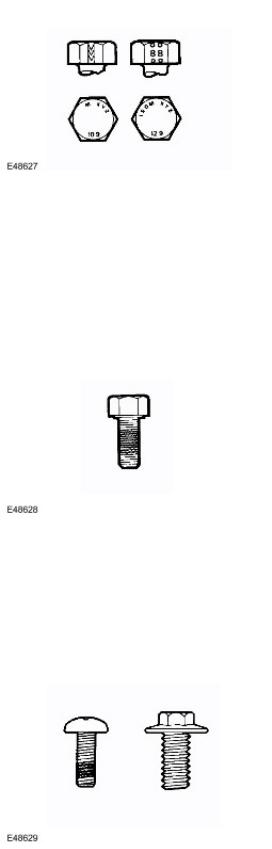
Bolt and Nut Identification
http://www.landrovertechinfo.com/extlrprod/frmviewit.jsp?szFrom=doc&iDocCode=276785 |
Page 4 of 25 |
http://www.landrovertechinfo.com/extlrprod/frmviewit.jsp?szFrom=doc&iDocCode=276785 |
07/16/2006 12:59 PM |
An ISO metric bolt or screw made of steel and larger than 6 mm in diameter can be identified by either of the symbols ISO M or M embossed or indented on top of the bolt head.
In addition to marks identifying the manufacturer, the top of the bolt head is also marked with symbols indicating the strength grade e.g. 8.8, 10.9, 12.9, 14.9. Alternatively, some bolts and screws have the M and strength grade symbol stamped on the flats of the hexagon.
Encapsulated ('Patched') bolts and screws
Encapsulated ('patched') bolts and screws have a thread locking agent applied to the threads during manufacture. Most thread locking agents are colored, the band of color extending for 360 degrees around the thread. Some locking agents however, are neutral in color and may not be so easily identified apart from a slightly darker area of thread where the locking agent has been applied. The locking agent is released and activated by the tightening process and is then chemically cured to provide the locking action.
Self-locking bolts and screws
Unless stated in a specific repair procedure, self-locking bolts and screws i.e. nylon patched or trilobular thread can be reused provided that resistance is felt when the locking portion enters the female thread.
Nylon patched bolts and screws have a locking agent either applied to, or inserted in the threaded portion. They are identified by the presence of a colored section of thread extending approximately 180 degrees around the thread or by a colored plug inserted into the bolt.
http://www.landrovertechinfo.com/extlrprod/frmviewit.jsp?szFrom=doc&iDocCode=276785 |
Page 5 of 25 |

http://www.landrovertechinfo.com/extlrprod/frmviewit.jsp?szFrom=doc&iDocCode=276785 |
07/16/2006 12:59 PM |
Trilobular bolts have a special thread form which creates a slight interference with the thread of the hole or nut into which it is screwed.
 CAUTION: Do Not reuse self-locking fasteners in critical locations e.g. drive plates/flywheel or engine bearings. Do not fit non self-locking fasteners where a self-locking fastener is specified.
Trilobular bolts should not be used as a substitute for patched bolts.
Nut identification
A nut with an ISO metric thread is marked on one face or one of the hexagonal flats with the strength grade symbol 8, 12, 14. Some nuts with the strength grade 4, 5 or 6 are also marked and some have the metric symbol M on the hexagonal flat opposite the strength grade marking.
A clock face system is sometimes used as an alternative method of indicating the strength grade. The external chamfers or a face of the nut is marked in a position relative to the appropriate hour mark on a clock face to indicate the strength grade.
A dot is used to locate the 12 o'clock position and a dash to indicate the strength grade. If the grade is above 12, two dots identify the 12 o'clock position.
When tightening a slotted or castellated nut, never loosen it to insert a split pin except where specified as part of an adjustment procedure. If difficulty is experienced in correctly positioning the slot, alternative washers or nuts should be selected.
Where a nut is tightened to adjust or maintain bearing pre-load, the tightening procedure must be adhered to.
Self-locking nuts
Unless stated in a specific repair procedure, self-locking nuts i.e. those with a nylon insert or deformed thread nuts can be reused provided that resistance can be felt when the locking portion of the nut passes over the thread of the bolt or stud.
Unless stated otherwise, self-locking nuts once removed must be discarded and new nuts of the same type and strength grade fitted.
http://www.landrovertechinfo.com/extlrprod/frmviewit.jsp?szFrom=doc&iDocCode=276785 |
Page 6 of 25 |

http://www.landrovertechinfo.com/extlrprod/frmviewit.jsp?szFrom=doc&iDocCode=276785 |
07/16/2006 12:59 PM |
Air Suspension
Always ensure that suitable eye protection is worn when working on the air suspension system.
Ball and Roller Bearings
When removing and installing bearings, ensure that the following practices are observed to ensure component serviceability:
 CAUTION: Service tools have been developed for removing the majority of bearings; these must always be used where specified.
Remove all traces from bearing under inspection by cleaning with a suitable degreasant; maintain absolute cleanliness throughout operations.
Conduct a visual inspection for markings on rolling elements, raceways, outer surfaces of outer or inner surfaces of inner rings. Reject any bearings found to be marked since marking in these areas indicates onset of wear.
Hold inner race of bearing between finger and thumb of one hand and rotate outer race to check that it revolves absolutely smoothly. Repeat holding outer race and rotating inner race. DO NOT spin the bearing.
Rotate outer ring gently using a reciprocating movement whilst holding inner ring; feel for any check or obstruction to rotation. Reject bearing if movement is not absolutely smooth.
Check bearing for blueing or signs of overheating. Lubricate bearing with the specified lubricant.
Inspect bearing surface of shaft and bearing housing for discoloration or other markings which indicate overheating of bearing or movement between bearing and seating.
Before fitting bearing, ensure that shaft and bearing housing are clean and free from burrs.
If one bearing of a pair shows signs of wear, overheating etc., it is advisable to replace bearings as a pair unless it is suspected that one bearing may have been faulty when fitted, was fitted incorrectly or the fault arose due to oil seal failure.
Never refit a bearing unless it is in a fully serviceable condition.
When fitting a bearing to a shaft, only apply force to the inner ring of the bearing. When fitting a bearing into a housing, only apply force to the outer ring of the bearing.
 CAUTION: Service tools have been developed for fitting the majority of bearings; these must always be used where specified.
In the case of grease lubricated bearings, fill the space between the bearing and outer seal with the recommended grade of grease before fitting the seal.
 CAUTION: When a waxed oil seal (fitted dry) type of oil seal is to be fitted, take great care that grease does not contaminate the running surface of the seal.
http://www.landrovertechinfo.com/extlrprod/frmviewit.jsp?szFrom=doc&iDocCode=276785 |
Page 7 of 25 |

http://www.landrovertechinfo.com/extlrprod/frmviewit.jsp?szFrom=doc&iDocCode=276785 |
07/16/2006 12:59 PM |
Always make suitable reference marks between the components of separable bearings e.g. taper roller bearings when disassembling to ensure correct location of components when assembling. Never fit new rollers in an outer ring, always fit a new bearing assembly.
Brake Pads and Linings
Always fit the correct grade and specification of brake pads and linings. When replacing these items, always replace as complete axle sets.
Brake Hydraulics
Always observe the following recommendations when working on the braking system:
 WARNING: Do not intermix brake fluid of different specifications.
Always use two spanners when loosening or tightening brake pipes or hose connections. Ensure that hoses run in a natural curve and are not kinked or twisted.
Fit brake pipes and hoses securely in their retaining clips and ensure that they cannot contact a potential chafing point.
Containers used for brake fluid must be kept absolutely clean.
Do not store brake fluid in unsealed containers, the fluid will absorb water which will lower the boiling point of the fluid.
Do not allow brake fluid to be contaminated with other fluids such as mineral oil and do not put brake fluid in a container which has previously been used for storing other fluids.
Do not reuse brake fluid which has been bled from the system.
Always use brake fluid or a suitable brake cleaning fluid to clean hydraulic components.
Unless stated otherwise, use only clean brake fluid to lubricate hydraulic seals and components. Always fit blanking plugs to hoses, pipes or components immediately after disconnection. Check thread compatibility of original equipment with replacement components.
Observe absolute cleanliness when working with hydraulic components.
Pipes and Hoses
When removing or installing flexible hydraulic pipes and hoses, ensure that the following procedures are observed to ensure component serviceability:
Prior to removal, clean area around hose or pipe end which is to be disconnected.
Obtain appropriate blanking plugs or caps before disconnecting hose or pipe end fittings in order that connections can be plugged immediately following disconnection.
Always fit blanking plugs or caps to pipes and unions immediately following disconnection. Clean hose or pipe and blow through with an air line.
 WARNING: Suitable eye protection must be worn.
Check hoses externally for cracks, separation of plies, security of end fittings and external damage; replace faulty hoses.
Check pipes for signs of corrosion and chafing, replace as necessary.
 CAUTION: If pipes are found to be chafed, rectify clips, mounting points etc., to prevent further problems in service.
When fitting hoses, ensure that no unnecesary bends are introduced and that hoses are not kinked, twisted or positioned close to potential chafing points.
When fitting pipes, ensure that pipes are positioned and clipped clear of potential chafing points.
http://www.landrovertechinfo.com/extlrprod/frmviewit.jsp?szFrom=doc&iDocCode=276785 |
Page 8 of 25 |

http://www.landrovertechinfo.com/extlrprod/frmviewit.jsp?szFrom=doc&iDocCode=276785 |
07/16/2006 12:59 PM |
Always replace sealing washers fitted to banjo bolts, sealing plugs etc.
Always use a backing spanner when tightening unions and do not overtighten union nuts or banjo bolts.
After any work on hydraulic systems, always check for fluid leaks whilst a second operator applies working pressure to the brake pedal or operates the system that has been worked on.
Fuel system hoses
All fuel hoses are made up of two laminations, an armored rubber outer sleeve and an inner viton core. Whenever a hose is removed, ensure that the inner bore is inspected to check that the viton lining has not become separated from the outer sleeve.
 WARNING: Never attempt to repair fuel foses or rectify leaking 'quick-fit' connectors the fuel hose and connectors must be replaced as an assembly.
Fuel system hose clips
Certain fuel system hose clips are of the 'break-off head' type where a slot in the screw head shears off when the clip is tightened to a specific torque. These clips may be removed using a screwdriver and must be replaced with new clips on reassembly. Clips must be tightened until the portion of the slot shears off. Do not attempt to tighten clips by any other method, do not fit any other type of clip.
Cooling system hoses
 CAUTION: The following precautions must be observed to ensure that the integrity of the cooling system hoses and their connection to the system is maintained.
http://www.landrovertechinfo.com/extlrprod/frmviewit.jsp?szFrom=doc&iDocCode=276785 |
Page 9 of 25 |

http://www.landrovertechinfo.com/extlrprod/frmviewit.jsp?szFrom=doc&iDocCode=276785 |
07/16/2006 12:59 PM |
Hose orientation and connection
Correct orientation of cooling system hoses is important to ensure that hoses do not become fatigued or damaged through contact with adjacent components.
Where orientation marks are provided on the hose and corresponding component, the marks must be aligned when the hose is fitted. Hoses must be fitted fully on to their connection points, usually a moulded form on a pipe provides a positive indicator.
Hose clips
Markings are usually provided on the hose to indicate the correct clip position. If no markings are provided, position the clip directly behind the retaining lip at the end of the stub pipe. Worm drive clips should be orientated with the crimped side of the drive housing facing towards the end of the hose or the hose may become pinched between the clip and the stub pipe retaining lip. Unless otherwise stated, worm drive clips should be tightened to 3 Nm (2 lbf.ft). Ensure that hose clips do not foul adjacent components.
Oetiker clips may be removed by bending the tag (arrowed) and releasing the free end of the clip. Clips must not be reused. When fitting new clips, ensure clip is positioned on hose before tightening and ensure that when clip is tightened, the tag is located in the longitudinal slot in the free end of the clip (arrowed in illustration).
http://www.landrovertechinfo.com/extlrprod/frmviewit.jsp?szFrom=doc&iDocCode=276785 |
Page 10 of 25 |
http://www.landrovertechinfo.com/extlrprod/frmviewit.jsp?szFrom=doc&iDocCode=276785 |
07/16/2006 12:59 PM |
Heat protection
Always ensure that heatshields and protective sheathing are in good condition; replace if damage is evident. Particular care must be taken when routing hoses close to hot engine components such as the exhaust manifolds and exhaust gas recirculation (EGR) pipes. Hoses will relax and deflect slightly when hot, ensure this movement is taken into account when routing and securing hoses.
Electrical Precautions
General
The following guidelines are intended to ensure the safety of the operator whilst preventing damage to the electrical and electronic components of this vehicle.
Equipment
Prior to commencing any test procedure on the vehicle, ensure that the relevant test equipment is working correctly and that any harness or connectors are in good condition. It is particularly important to check the condition of all plugs and leads of mains operated equipment.
Polarity
Never reverse connect the vehicle battery and always ensure the correct polarity when connecting test equipment.
High voltage circuits
Whenever disconnecting live ht circuits, always use insulated pliers and never allow the open end of the ht lead to contact other components, particularly ECU's.
Vehicles fitted with Bi-Xenon headlamp bulbs
 WARNING: The following precautions must be observed as failure to comply may result in exposure to ultra-violet rays, severe electric shock, burns or risk of an explosion.
Safety goggles and gloves must be worn.
Ensure that headlamps are switched off before removing bulbs.
Do not touch the glass portion of the bulb.
On no account should headlamps be switched on with the bulb removed from the headlamp.
Bulb testing may only be carried out with the bulb fitted in the headlamp.
Bulbs must be disposed of in accordance with the local authority bye-laws.
Connectors and harnesses
The engine compartment of a vehicle is a particularly hostile environment for electrical components and connectors. Always observe the following:
Ensure electrically related items are dry and oil free before disconnecting/connecting test equipment. Ensure that disconnected multiplugs and sensors are protected from any possible oil, coolant or other liquid contamination. Any such contamination could impair performance or lead to component failure.
Never force connectors apart or pull on the wiring harness.
Always ensure locking tabs are disengaged before disconnecting multiplugs etc. and ensure that correct orientation is achieved before connection.
Ensure that any protection covers, insulation etc. are replaced if disturbed.
Having confirmed that a component is faulty, carry out the following:
http://www.landrovertechinfo.com/extlrprod/frmviewit.jsp?szFrom=doc&iDocCode=276785 |
Page 11 of 25 |

http://www.landrovertechinfo.com/extlrprod/frmviewit.jsp?szFrom=doc&iDocCode=276785 |
07/16/2006 12:59 PM |
Switch off the ignition and disconnect the battery.
Remove the component and support the disconnected harness.
When replacing electrical components, keep oily hands away from electrical connections and ensure that locking tabs on connectors are fully engaged.
Battery Disconnection/Connection
Always refer to the Electrical Section of this manual - Battery Connection/Disconnection prior to attempting to connect or disconnect the battery. For additional information, refer to Specifications (414-00 Charging System - General Information)
Fuel Handling Precautions
The following information lists basic precautions which must be observed if fuel is to be handled safely. It also outlines other areas of risk which must not be ignored. As this information is issued for basic guidance only, consult your local Fire Department where any doubt as to personal and environmental safety exists - See also Health and Safety Precautions.
General precautions
Always have the correct type of fire extinguisher containing Foam, CO2, Gas or powder accessible when handling or draining fuel or dismantling fuel systems. Fire extinguishers must also be located in areas where fuel is stored.
Ensure that suitable warning signs are exhibited.
Keep all sources of ignition well away from areas where fuel is being handled.
Ensure that any leadlamps are flameproof and kept clear of spillage.
 WARNING: Do not disassemble or reassemble fuel system components whilst vehicle is over a pit.
 WARNING: No one should be permitted to repair components associated with fuel without first having specialist training.
Always disconnect the vehicle battery before carrying out disassembly, reassembly or draining work on a fuel system.
Fuel tank and system draining
Draining must be carried out in accordance with the procedures given in the relevant Fuel System section of this manual.
 WARNING: Never drain fuel or work on a fuel system while the vehicle is over a pit. Extraction or draining of fuel must be carried out in a well ventilated area.
 WARNING: Always attach fuel vapor warning labels to fuel tanks immediately after draining.
 WARNING: Containers used for storing fuel must be clearly marked with the contents and placed in a safe storage area which meets the requirements of the local authority.
http://www.landrovertechinfo.com/extlrprod/frmviewit.jsp?szFrom=doc&iDocCode=276785 |
Page 12 of 25 |

http://www.landrovertechinfo.com/extlrprod/frmviewit.jsp?szFrom=doc&iDocCode=276785 |
07/16/2006 12:59 PM |
 CAUTION: Some fuel lines are now fitted with 'quick release' connectors. If a connector is damaged, no attempt must be made to repair the connector, a new fuel line and connector(s) assembly must be fitted.
Always release pipe clips fully before attempting to disconnect fuel pipes.
Fuel tank repairs
 CAUTION: No attempt should be made to repair a plastic fuel tank. If the structure of the tank is damaged, a new tank must be fitted.
Oil seals
Always renew oil seals which have been removed either as an individual component or as part of an assembly. Never use a seal which has been improperly stored or handled.
Take great care when removing old seals that the sealing surfaces and seal housing are not damaged. Carefully examine seal before fitting to ensure that it is clean and undamaged.
Ensure that the surface on which the seal is to run and also the seal housing is clean and free from burrs or scratches. Renew the component if the sealing surface cannot be restored.
Special tools and protection sleeves are provided for fitting the majority of seals and must be used when specified. Many seals are now coated with a protective wax and DO NOT need to be lubricated prior to fitting. Always check the relevant repair procedure which will state if a seal must be fitted dry. Never touch these seals with oily hands as the oil will contaminate the protective coating and affect the sealing properties of the seal; also, ensure that fitting tools and protection sleeves are free from oil and grease. Seals which must be lubricated prior to fitting should have the recommended lubricant applied to the areas specified in the repair procedure.
Ensure that a seal is fitted the correct way round. For example, the lip of the seal must face towards the lubricant which it is sealing.
When fitting an oil seal, ensure that it is positioned square to shaft and housing. Where the seal is to be fitted to a housing prior to fitting over a shaft, take care not to allow the weight of an unsupported shaft to rest on the seal.
Always use the recommended special tool and protection sleeve to fit an oil seal. If no tool is specified, use a suitable mandrel approximately 0.4 mm (0.015 in) smaller than the outside diameter of the seal. Use adhesive tape on the shaft to protect the sealing lip of the seal.
http://www.landrovertechinfo.com/extlrprod/frmviewit.jsp?szFrom=doc&iDocCode=276785 |
Page 13 of 25 |

http://www.landrovertechinfo.com/extlrprod/frmviewit.jsp?szFrom=doc&iDocCode=276785 |
07/16/2006 12:59 PM |
Press or drift the seal in to the depth of its housing if the housing is shouldered or flush with the face of the housing where no shoulder is provided. Ensure that the seal is not tilted in the housing when it is fitted.
Supplementary Restraint System (SRS) Precautions
 WARNING: Do not fit rear facing child seats in the front passenger seat.
The SRS contains components which are potentially hazardous to service personnel if not handled correctly. The following guidelines and precautions are intended to alert personnel to potential sources of danger and emphasise the importance of ensuring the integrity of the SRS components fitted to the vehicle.
 WARNING: The following precautions MUST be adhered to when working on the SRS system:
The correct procedures must always be used when working on SRS components.
Persons working on the SRS system must be fully trained and have been issued with the safety guidelines. The airbag modules contain extremely flammable and hazardous compounds. Contact with water, acids or heavy metals may produce harmful or explosive results. Do not dismantle, incinerate or bring into contact with electricity before the unit has been deployed.
Always replace a seat belt assembly that has withstood the strain of a severe vehicle impact or if the webbing shows signs of fraying.
Always disconnect the vehicle battery before carrying out any electric welding on a vehicle fitted with an SRS system.
 CAUTION: Do not expose airbag modules or seat belt pre-tensioners to temperatures exceeding 85° C (185° F).
It should be noted that these precautions are not restricted to operations performed when servicing the SRS system. The same care should be exercised when working on ancillary systems and components located in the vicinity of SRS components; these include but are not limited to:
Steering wheel airbag, rotary coupler.
Passenger front airbag.
Head airbag modules - front and rear.
Seat belt pre-tensioners.
SRS harnesses, link leads and connectors.
Side (thorax) air bags.
Making the system safe
Before working on or in the vicinity of SRS components, ensure the system is rendered safe by performing the following operations:
http://www.landrovertechinfo.com/extlrprod/frmviewit.jsp?szFrom=doc&iDocCode=276785 |
Page 14 of 25 |

http://www.landrovertechinfo.com/extlrprod/frmviewit.jsp?szFrom=doc&iDocCode=276785 |
07/16/2006 12:59 PM |
Remove the ignition key.
Disconnect battery, earth lead first.
Wait 2 minutes for the SRS power circuit to discharge before commencing work.
NOTE:
The SRS uses energy reserve capacitors to keep the system active in the event of electrical supply failure under crash conditions. It is necessary to allow the capacitors sufficient time to discharge (2 minutes) in order to avoid the risk of accidental deployment.
Installation
In order to ensure system integrity, it is essential that the SRS system is regularly checked and maintained so that it is ready for effective operation in the event of a collision. Carefully inspect SRS components before installation. Do not install a part that shows signs of being dropped or improperly handled, such as dents, cracks or deformation.
 WARNING: The integrity of the SRS systems is critical for safety reasons. Ensure the following precautions are always adhered to:
Do not fit accessories or other objects to trim panels which cover ITS airbags.
Never install used SRS components from another vehicle or attempt to repair an SRS component. When repairing an SRS system, only use genuine new parts.
Never apply electrical power to an SRS component unless instructed to do so as part of an approved test procedure.
Special fixings are necessary for installing an airbag module – do not use other fixings and ensure that all fixings are tightened to the correct torque.
Always use new fixings when replacing an SRS component.
 CAUTION: Take care not to trap airbag modules when fitting interior trim components.
 CAUTION: Ensure SRS components are not contaminated by oil or grease.
NOTE:
Following seat belt pre-tensioner deployment, the seat belts can still be used as conventional seat belts but will need to be replaced as soon as possible to ensure full SRS protection.
NOTE:
If the SRS components are to be replaced, the part number/bar code of the new unit must be recorded.
SRS component testing precautions
The SRS components are triggered using relatively low operating currents, always adhere to the following :
 WARNING: Never use a multimeter or other general purpose equipment on SRS components. Use only T4 to diagnose system faults.
http://www.landrovertechinfo.com/extlrprod/frmviewit.jsp?szFrom=doc&iDocCode=276785 |
Page 15 of 25 |

http://www.landrovertechinfo.com/extlrprod/frmviewit.jsp?szFrom=doc&iDocCode=276785 |
07/16/2006 12:59 PM |
 WARNING: Do not use electrical test equipment on the SRS harness while it is connected to any of the SRS components, it may cause accidental deployment and injury.
Handling and storage
Always observe the following precautions when handling SRS components:
Never drop an SRS component. The airbag diagnostic control unit is a particularly shock sensitive device and must be handled with extreme care. Airbag modules and seat belt pre-tensioners could deploy if subjected to a strong shock.
Never wrap your arms around an airbag module. If a module has to be carried, hold it by the cover with the cover uppermost and the base away from your body.
Never transport airbag modules or seat belt pre-tensioners in the passenger compartment of a vehicle. Always use the luggage compartment of the vehicle for carrying airbag modules and seat belt pre-tensioner units.
Never attach anything to an airbag cover or any trim component covering an airbag module. Do not allow anything to rest on top of an airbag module.
Always keep components cool, dry and free from contamination.
Never apply grease or cleaning solvents to seat belt pre-tensioner units, component failure could result.
Always store an airbag module with the deployment side uppermost. If it is stored deployment side down, accidental deployment will propel the airbag module with sufficient force to cause serious injury.
Keep new airbag modules in their original packaging until just prior to fitting. Place the old module in the empty packaging for carriage.
http://www.landrovertechinfo.com/extlrprod/frmviewit.jsp?szFrom=doc&iDocCode=276785 |
Page 16 of 25 |

http://www.landrovertechinfo.com/extlrprod/frmviewit.jsp?szFrom=doc&iDocCode=276785 |
07/16/2006 12:59 PM |
 WARNING: When handling an inflatable tubular structure (ITS) airbag module, hold by the gas generator housing, DO NOT hold by the airbag. Do not wrap the thumb around the gas generator while holding. Do not drape airbag over shoulder or around neck. For seat buckle type pre-tensioners, hold by the piston tube, with the open end of the piston tube pointing towards the ground and the buckle facing away from your body. Do not cover the end of the piston tube. DO NOT hold buckle type pre-tensioners by the bracket assembly or cable. Never point the piston tube towards your body or other people.
 WARNING: Airbag modules and seat belt pre-tensioners are classed as explosive devices. For overnight and longer term storage, they must be stored in a secure steel cabinet which has been approved as suitable for the purpose and has been registered with the local authority.
 WARNING: Store airbag modules or seat belt pre-tensioners in a designated storage area. If there is no designated storage area available, store in the locked luggage compartment of the vehicle and inform the workshop supervisor.
 CAUTION: Improper handling or storage can internally damage the airbag module making it inoperative. If you suspect the airbag module has been damaged, install a new module and refer to the deployment/disposal procedures for disposal of the damaged module.
SRS harness and connectors
Always observe the following precautions with regards to SRS system electrical wiring:
Never attempt to modify, splice or repair SRS wiring.
Never install electrical equipment such as a mobile telephone, two-way radio or in-car entertainment system in such a way that it could generate electrical interference in the airbag harness. Seek specialist advice when installing such equipment.
http://www.landrovertechinfo.com/extlrprod/frmviewit.jsp?szFrom=doc&iDocCode=276785 |
Page 17 of 25 |

http://www.landrovertechinfo.com/extlrprod/frmviewit.jsp?szFrom=doc&iDocCode=276785 |
07/16/2006 12:59 PM |
NOTE:
SRS wiring can be identified by a special yellow outer sleeve protecting the wires (black with yellow stripe protective coverings are sometimes used).
 WARNING: Always ensure SRS wiring is routed correctly. Be careful to avoid trapping or pinching the SRS wiring.
 WARNING: Do not leave the connectors hanging loose or allow SRS components to hang from their harnesses. Look for possible chafing points.
Side impact crash sensor inspection
After any degree of side body damage, inspect the side impact crash sensors. Replace a crash sensor if there is any sign of damage.
 CAUTION: Take extra care when painting or carrying out bodywork repairs in the vicinity of the crash sensors. Avoid direct exposure of the crash sensors or link harnesses to heat guns, welding or spraying equipment. Take care not to damage sensor or harness when refitting components.
Rotary coupler
 CAUTION: Always follow the procedure for fitting and checking the rotary coupler as instructed in the SRS repairs section. Comply with all safety and installation procedures to ensure the system functions correctly. Observe the following precautions:
http://www.landrovertechinfo.com/extlrprod/frmviewit.jsp?szFrom=doc&iDocCode=276785 |
Page 18 of 25 |

http://www.landrovertechinfo.com/extlrprod/frmviewit.jsp?szFrom=doc&iDocCode=276785 |
07/16/2006 12:59 PM |
Do not unlock and rotate the rotary coupler when it is removed from the vehicle. Do not turn the road wheels when the rotary coupler is removed from the vehicle.
Always ensure the rotary coupler is removed and installed in its central position and with the front road wheels in the straight ahead position - refer to SRS repair section for the correct removal and installation procedure.
If a new rotary coupler is being installed, ensure the locking tab holding the coupler's rotational position is not broken; units with a broken locking tab must not be used.
Airbag location labels
WAITING AIRBAG LOCATION AND DESIGN LABELS - DUE MARCH - NEIL HARRISON 46404
Airbag and pre-tensioner deployment
 WARNING: During deployment parts of the airbag module become hot enough to burn you. Wait 30 minutes after deployment before touching the airbag module.
Deployment procedures and precautions as detailed in this manual should be strictly adhered to. Only personnel who have undergone the appropriate training should undertake deployment of airbag and pre-tensioner modules. The following precautions must be complied with:
Only use deployment equipment approved for the intended purpose.
Deployment of airbag / pre-tensioner modules must be performed in a well ventilated area which has been designated for the purpose.
Ensure airbag / pre-tensioner modules are not damaged or ruptured before attempting to deploy.
Where local legislation exists, notify the relevant authorities of intention to deploy airbag and pretensioner units. When deploying airbag pre-tensioner units, ensure that all personnel are at least 15 metres (45 feet) away from the deployment zone.
Ensure deployment tool is connected correctly, in compliance with the instructions detailed in the SRS section of this manual. In particular, ensure deployment tool is NOT connected to battery supply before connecting to airbag module connector.
When deploying seat belt pre-tensioners, ensure pre-tensioner unit is secured correctly to the seat.
When removing deployed airbag modules and pre-tensioner units, wear protective clothing. Use gloves and seal deployed units in a plastic bag.
Following deployment of any component of the SRS system within the vehicle, all SRS components must be replaced. DO NOT reuse or salvage any parts of the SRS system.
Do not lean over an airbag module when connecting deployment equipment.
If a vehicle is to be scrapped, undeployed airbag modules and pre-tensioner units must be manually deployed. In this case airbags can be deployed in the vehicle. Before deployment, ensure the airbag module is secure within its correct mounting position. Deployment of the driver's airbag in the vehicle may damage the steering wheel; if the vehicle is not being scrapped, deploy the module outside of the vehicle.
SRS Component Replacement Policy
 CAUTION: The Restraints Control Module (RCM) will log a crash fault after every impact which is severe enough to cause airbag deployment. It is possible to have three crashes/impacts logged after one event where, for example, a front, side and rollover has occurred. After the third fault is logged, the SRS warning lamp will be illuminated and the restraints control module (RCM) must be replaced.
 CAUTION: The SRS side impact sensor must be replaced if there are any signs of physical damage or if the restraints control module (RCM) is registering a fault.
The following information details the policy for replacement of SRS components as a result of a vehicle accident.
http://www.landrovertechinfo.com/extlrprod/frmviewit.jsp?szFrom=doc&iDocCode=276785 |
Page 19 of 25 |

http://www.landrovertechinfo.com/extlrprod/frmviewit.jsp?szFrom=doc&iDocCode=276785 |
07/16/2006 12:59 PM |
Impacts which do not deploy the airbags or pre-tensioners
Check for structural damage in the area of the impact paying particular attention to bumper armatures, longitudinals and bracketry.
Impacts which deploy the airbags or pre-tensioners
The replacement and inspection policy is dependent on the type and severity of the crash condition. The following guidelines are the minimum that should be exercised as a result of the deployment of specific SRS components.
Check for structural damage in the area of impact paying particular attention to bumper armatures, longitudinals and bracketry.
Front Airbag Deployment - Driver and Passenger
 CAUTION: If the front airbags are deployed, the following components must be replaced:
Driver airbag module Passenger airbag module
Fly leads (where applicable) connecting front airbag modules to SRS harness Front seat belt buckle pre-tensioner
Rear seat belt pre-tensioners - if fitted Driver's seat belt retractor - if fitted Rotary coupler
Any front impact sensors that have been physically damaged or if a fault is being registered Restraints control module (RCM) if the three crashes/impacts have been stored
Additionally, the following items must be inspected for damage and replaced as necessary:
Front passenger's seat belt retractor and webbing, tongue latching function, 'D' loop and body anchorage point Rear seat belt buckles, webbing, buckle covers, body anchorage points and tongue latching function
Fascia moulding adjacent to passenger airbag module Steering wheel
Front seat frames and head restraints
Steering column - if adjustment is lost or if there are signs of collapse Seat belt height adjusters
Rear seat belts
Side Air Bags
 CAUTION: If the side (thorax) air bags are deployed, the following components must be replaced on the side of the vehicle on which the deployment occurred:
Side (thorax) airbag
Any side impact sensors that have been physically damaged or if a fault is being registered Restraints Control Module (RCM) if the three crashes/impacts have been stored
Additionally, the following items must be inspected for damage and replaced as necessary:
Front seat belts, retractors and webbing, tongue latching function, 'D' loop and body anchorage points Rear seat belt buckles, webbing, buckle covers, tongue latching function, and body anchorage points Front seat frame and head restraints
Door trim casing
Seat belt height adjusters Rear seat belts
http://www.landrovertechinfo.com/extlrprod/frmviewit.jsp?szFrom=doc&iDocCode=276785 |
Page 20 of 25 |
http://www.landrovertechinfo.com/extlrprod/frmviewit.jsp?szFrom=doc&iDocCode=276785 |
07/16/2006 12:59 PM |
Head airbag modules
 CAUTION: If the head airbag modules are deployed, the following components must be replaced on the side of the vehicle on which the deployment occurred:
Head airbag modules
Link lead between airbag gas generator and restraints control module (RCM) harness
Airbag retaining clips
Internal trim finisher
Front seat belt buckle pre-tensioners
Any side impact sensors that have been physically damaged or if a fault is being registered
Restraints Control Module (RCM) if the three crashes/impacts have been stored
Additionally, the following items must be inspected for damage and replaced as necessary:
Headlining
Component mounting brackets
Front seat belts, retractors and webbing, tongue latching function, 'D' loop and body anchorage points Rear seat belt buckles, webbing, buckle covers, tongue latching function, and body anchorage points Adjacent trim components
Seat belt height adjusters
Rear impacts
 CAUTION: If the seat belt pre-tensioners are deployed during a rear impact, the following components must be replaced:
Seat belt pre-tensioners
Front and rear seat belt retractors used during the impact
Restraints Control Module (RCM) if the three crashes/impacts have been stored
Additionally, the following items must be inspected for damage and replaced as necessary:
Seat belt height adjusters
Front seat belts, retractors and webbing, tongue latching function, 'D' loop and body anchorage points Rear seat belt buckles, webbing, buckle covers, tongue latching function, and body anchorage points
Air Conditioning System Precautions
The air conditioning system contains fluids and components which could be potentially hazardous to the service engineer or the environment if not serviced and handled correctly. The following guidelines are intended to alert the service engineer to potential sources of danger and emphasise the importance of ensuring the integrity of the Air Conditioning operating conditions and components fitted to the vehicle.
Where necessary, additional specific precautions are detailed in the relevant sections of this Manual and also in the Health and Safety Section. These precautions must be referred to prior to commencing repair operations.
The refrigerant used in the air conditioning system is HFC-134a (Hydrofluorocarbon) R134a.
 WARNING: Servicing must only be carried out by personnel familiar with both the vehicle system and the charging and testing equipment. All operations must be carried out in a well ventilated area away from open flame
http://www.landrovertechinfo.com/extlrprod/frmviewit.jsp?szFrom=doc&iDocCode=276785 |
Page 21 of 25 |

http://www.landrovertechinfo.com/extlrprod/frmviewit.jsp?szFrom=doc&iDocCode=276785 |
07/16/2006 12:59 PM |
and heat sources.
 WARNING: R134a is a hazardous liquid and when handled incorrectly can cause serious injury. Suitable protective clothing, consisting of face protection, heat proof gloves, rubber boots and rubber apron or waterproof overalls, must be worn when carrying out operations on the air conditioning system.
Remedial actions
 WARNING: Due to its low evaporating temperature, R134a must be handled with care. R134a splashed on any part of the body will cause immediate freezing of that area. Also, refrigerant cylinders and replenishment trolleys when discharging will freeze skin to them if contact is made.
If an accident involving R134a should occur, conduct the following remedial actions:
If liquid R134a enters the eye, do not rub it. Gently run large quantities of eye wash over affected eye to raise the temperature. If an eye wash is not available, cool, clean water may be used to flush the eye. After rinsing, cover the eye with a clean pad and seek immediate medical attention.
If liquid R134a is splashed onto the skin, run large quantities of water over the affected area to raise the temperature. Implement the same action if the skin comes in contact with discharging cylinders. Wrap the contaminated body parts in blankets (or similar materials) and seek immediate medical attention.
If the debilitating effects of inhalation of R134a vapour are suspected, seek fresh air. If the affected person is unconscious, move them away from the contaminated area to fresh air and apply artificial respiration and/or oxygen and seek immediate medical attention.
Service precautions
Observe the following precautions when handling components used in the air conditioning system:
Air conditioning units must not be lifted by their hoses, pipes or capillary lines.
Hoses and lines must not be subjected to any twist or stress; the efficiency of the system will be impaired by kinks or restrictions. Ensure that hoses are correctly positioned before tightening couplings, and ensure that all clips and supports are utilised.
Flexible hoses should not be positioned closer than 100 mm (4.0 in) to the exhaust manifold unless protected by heat shielding.
Completed assemblies must be checked for refrigeration lines touching metal panels. Any direct contact of components and panels may transmit noise and so must be eliminated.
The appropriate torque wrench must be used when tightening refrigerant connections to the stipulated value. An additional spanner must be used to hold the union to prevent twisting of the pipe when tightening connections. Before connecting any hose or pipe, ensure that refrigerant oil is applied to the seat of the new 'O' rings, BUT NOT to the threads of the connection.
All protective plugs or caps must remain in place in the component until immediately prior to connection. Ensure components are at room temperature before uncapping/unplugging, to prevent condensation of moisture from the air that enters it.
When disconnecting, immediately plug or cap all air conditioning pipes to prevent ingress of dirt and moisture into the system.
Components must not remain uncapped/unplugged, if a system has been left uncapped/unplugged for 20 minutes or longer, a new receiver/drier must be fitted.
The receiver/drier contains desiccant which absorbs moisture. It must be positively sealed at all times. A receiver/drier that has been left uncapped for longer than 20 minutes must not be used; fit a new unit.
The receiver/drier should be the last component connected to the system to ensure optimum dehydration and maximum moisture protection of the system.
Whenever a component of the refrigeration system is replaced, it will also be necessary to fit a new receiver/drier unit.
Use alcohol and a clean lint-free cloth to clean dirty connections.
http://www.landrovertechinfo.com/extlrprod/frmviewit.jsp?szFrom=doc&iDocCode=276785 |
Page 22 of 25 |

http://www.landrovertechinfo.com/extlrprod/frmviewit.jsp?szFrom=doc&iDocCode=276785 |
07/16/2006 12:59 PM |
Ensure that all new parts fitted are marked for use with R134a.
When a major repair has been completed, a leak test should be conducted; refer to the Repairs Section of this manual for the correct procedure.
Refrigerant oil
 CAUTION: Refrigerant oil easily absorbs water and must not be stored for long periods. Do not pour unused refrigerant oil back into the container. Always use an approved refrigerant oil.
When replacing components in the air conditioning system, drain the refrigerant oil from the component being replaced into a graduated container. On assembly, add the quantity of refrigerant oil drained to the new component - See Air Conditioning Compressor Replacement in this Section.
Compressor
A new compressor is sealed and pressurised with Nitrogen gas. When fitting a new compressor, slowly release the sealing cap; gas pressure should be heard to vent as the seal is broken.
 CAUTION: A new compressor should always be sealed and could be pressurised with nitrogen gas. To avoid possible oil loss, release the sealing cap(s) slowly. Do not remove the cap(s) until immediately prior to connecting the air conditioning pipes to the compressor.
Rapid refrigerant discharge
If the air conditioning system is involved in accident damage and the system is punctured, the refrigerant will discharge rapidly. The rapid discharge of refrigerant will also result in the loss of most of the oil from the system. The compressor must be removed and all the remaining oil in the compressor drained and refilled as instructed in the air conditioning section of this manual.
Precautions for refrigerant recovery, recycling and recharging
When the air conditioning system is recharged, any existing refrigerant is first recovered from the system and recycled. The system is then charged with the required weight of refrigerant and volume of refrigerant oil.
 WARNING: Refrigerant must always be recycled before reuse to ensure that the purity of the refrigerant is high enough for safe use in the air conditioning system. Recycling should always be carried out with equipment which is design certified by Underwriter Laboratory Inc. for compliance with SAE J1991. Other equipment may not recycle refrigerant to the required level of purity.
 CAUTION: A R134a Refrigerant Recovery Recycling Recharging Station must not be used with any other type of refrigerant. Refrigerant R134a from domestic and commercial sources must not be used in motor vehicle air conditioning systems.
http://www.landrovertechinfo.com/extlrprod/frmviewit.jsp?szFrom=doc&iDocCode=276785 |
Page 23 of 25 |

http://www.landrovertechinfo.com/extlrprod/frmviewit.jsp?szFrom=doc&iDocCode=276785 |
07/16/2006 12:59 PM |
 CAUTION: The system must be evacuated immediately before recharging commences. Delay between evacuation and recharging is not permitted.
Air Conditioning Compressor Replacement
A new compressor is supplied filled with a full charge (X cm³) of refrigerant oil.
A calculated quantity of oil must be drained from the new compressor before fitting. To calculate the quantity of oil to be drained:
Remove the drain plug from the old compressor.
Invert the compressor and gravity drain the oil into a calibrated measuring cylinder. Rotate the compressor clutch to ensure the compressor is completely drained.
Note the quantity of oil drained (Y cm³).
Calculate the quantity of oil to be drained from the new compressor using the following formula:X cm³ — (Y cm³ +
20 cm³) = Q cm³
Remove the drain plug from the new compressor and drain Q cm3 of oil. Fit and tighten the compressor drain plug.
Vehicle Weights
Item |
kg |
lb |
Maximum Gross Vehicle Weight (GVW) |
|
|
Petrol engine vehicles naturally aspirated |
3070 |
6768 |
Petrol engine vehicles supercharged |
3125 6889 |
|
Diesel engine vehicles |
3070 |
6768 |
Maximum weight of unbraked trailer: |
|
|
On-road |
750 |
1650 |
Off-road |
750 |
1650 |
Maximum towable weight (mass) - Trailers with overrun brakes |
|
|
On-road |
3500 7700 |
|
Off-road |
1000 2205 |
|
Maximum roof rack load (Including the mass of the roof rack):
On-road |
75 |
110 |
Off-road |
75 |
110 |
Vehicle Dimensions
Item |
mm |
in |
Length - including number plate plinth - All models |
4798 |
188.9 |
Width - All models: |
|
|
Mirrors extended |
2170 |
85.4 |
Mirrors folded |
1983 |
78.1 |
Maximum height - At standard ride height - All models: |
|
|
With roof rack and rails |
1784 |
70.2 |
With roof antenna module |
1812 |
71.3 |
With sunroof open |
1817 |
71.5 |
Wheelbase - All models |
2745 |
108 |
http://www.landrovertechinfo.com/extlrprod/frmviewit.jsp?szFrom=doc&iDocCode=276785 |
Page 24 of 25 |

http://www.landrovertechinfo.com/extlrprod/frmviewit.jsp?szFrom=doc&iDocCode=276785 |
07/16/2006 12:59 PM |
Front overhang - All models |
880 |
45.8 |
Rear overhang - All models |
1163 |
44.5 |
Track - All models: |
|
|
Front |
1605 |
63.2 |
Rear |
1612 |
63.5 |
Underbody Clearences: |
|
|
Standard ride height - Running clearance to exhaust - Minimum - Kerb weight |
172 |
6.8 |
Standard ride height - Ground to front undertray clearance |
188 |
7.4 |
Standard ride height - Ground to rear differential casing clearance |
200 |
7.9 |
Off-road height - Running clearance to exhaust - Minimum - Kerb weight |
227 |
8.9 |
Off-road height - Ground to front undertray clearance |
243 |
9.6 |
Off-road height - Ground to rear differential casing clearance |
255 |
10 |
Suspension articulation - All models: |
|
|
Front |
255 |
10.03 |
Rear |
310 |
12.2 |
Departure angle - Towbar NOT fitted: |
|
|
Standard ride height with full size spare wheel |
24.1° |
24.1° |
Standard ride height with space saver wheel |
26° |
26° |
Off-road height with full size spare wheel |
27.4° |
27.4° |
Off-road height with full space saver wheel |
29° |
29° |
Departure angle - Towbar fitted - NOT NAS vehicles: |
|
|
Standard ride height |
15.1° |
15.1° |
Off-road ride height |
17.8° |
17.8° |
Departure angle - Towbar fitted - NAS vehicles: |
|
|
Standard ride height |
13.9° |
13.9° |
Off-road ride height |
16.9° |
16.9° |
Departure angle - Adjustable height towbar fitted: |
|
|
Standard ride height |
13.3° |
13.3° |
Off-road ride height |
16° |
16° |
Wading depth: |
|
|
Off-road height |
700 |
27.5 |
Approach angle: |
|
|
Standard ride height |
30.2° |
30.2° |
Off-road ride height |
34° |
34° |
Ramp angle: |
|
|
Standard ride height |
20° |
20° |
Off-road ride height |
25° |
25° |
http://www.landrovertechinfo.com/extlrprod/frmviewit.jsp?szFrom=doc&iDocCode=276785 |
Page 25 of 25 |

http://www.landrovertechinfo.com/extlrprod/frmviewit.jsp?szFrom=doc&iDocCode=276785 |
07/16/2006 01:45 PM |
Published: Jan 6, 2005
Rear Stabilizer Bar
Removal
 CAUTION: It is possible to install the stabilizer bar incorrectly. Note the position of the stabilizer bar before removal.
 CAUTION: Dynamic Response system components are manufactured to very precise tolerances. It is therefore essential that absolute cleanliness is observed when working with these components. Always install blanking plugs to any open orifices or lines. Failure to follow this instruction may result in foreign matter ingress to the Dynamic Response system.
1
.
WARNING: Do not work on or under a vehicle supported only by a jack. Always support the vehicle on safety stands.
Raise and support the vehicle.
2 . Remove the rear bumper cover.
For additional information, refer to Rear Bumper Cover (76.22.74)
3 . Remove the spare wheel and tire.
4 . Raise the vehicle.
5 . Remove the rear wheels and tires.
6
.
CAUTION: Before disconnecting or removing the components, ensure the area around the joint faces and connections are clean. Plug open connections to prevent contamination.
 CAUTION: Make sure the actuator fluid lines are not damaged or kinked during removal or installation.
NOTE:
Some fluid spillage is inevitable during this operation.
Disconnect the fluid lines from the actuator.
 Position container to collect fluid loss.
 Remove the 2 bolts.
 Remove and discard the plastic spacer washers.
 Remove and discard the O-ring seals.
 Install blanking caps to the exposed ports.
http://www.landrovertechinfo.com/extlrprod/frmviewit.jsp?szFrom=doc&iDocCode=276785 |
Page 1 of 4 |

http://www.landrovertechinfo.com/extlrprod/frmviewit.jsp?szFrom=doc&iDocCode=276785 |
07/16/2006 01:45 PM |
7 .
CAUTION: Use a wrench on the hexagon provided to prevent the ball joint rotating.
Release both stabilizer bar links.
 Remove the 2 nuts.
8 . Remove the body mount retaining bolts.  Remove the 8 bolts.
9 .
CAUTION: Only raise the body sufficiently to remove the body mount.
Raise the body.
 Using suitable stands, raise the body to release the body mounts.
10 . Remove the 2 rear body mounts.
http://www.landrovertechinfo.com/extlrprod/frmviewit.jsp?szFrom=doc&iDocCode=276785 |
Page 2 of 4 |

http://www.landrovertechinfo.com/extlrprod/frmviewit.jsp?szFrom=doc&iDocCode=276785 |
07/16/2006 01:45 PM |
11 . Remove the stabilizer bar and actuator assembly bushings.
 Remove the 4 bolts.
  Remove the 2 clamps.
12 . NOTE:
Note the fitted position.
With assistance, remove the stabilizer bar and actuator assembly.
Installation
1 .
CAUTION: Make sure the stabilizer bar is correctly installed.
With assistance, install the stabilizer bar and actuator assembly. 2 . Install the stabilizer bar and actuator assembly bushings.
3 . Install the stabilizer bar clamps.
 Tighten the 4 retaining bolts to 62 Nm (46 lb.ft).
4 .
CAUTION: Use a wrench on the hexagon provided to prevent the ball joint rotating.
Connect the RH stabilizer bar link.
 Install a new nut and tighten to 115 Nm (85 lb.ft).
http://www.landrovertechinfo.com/extlrprod/frmviewit.jsp?szFrom=doc&iDocCode=276785 |
Page 3 of 4 |

http://www.landrovertechinfo.com/extlrprod/frmviewit.jsp?szFrom=doc&iDocCode=276785 |
07/16/2006 01:45 PM |
5
.
CAUTION: Make sure the actuator fluid lines are not damaged or kinked during removal or installation.
 CAUTION: Care must be taken to avoid damage to the plastic spacer washers and O-ring seals during installation of the fluid lines to the actautor.
NOTE:
Some fluid spillage is inevitable during this operation.
Connect the fluid lines to the actuator.
 Clean the component mating faces.
 Remove the blanking caps from the ports.
 Install new plastic spacer washers and O-ring seals.
 Tighten the 2 bolts to 22 Nm (16 lb.ft).
6 . Bleed the rear of the Dynamic Response system using T4.
7 .
CAUTION: Use a wrench on the hexagon provided to prevent the ball joint rotating.
Connect the LH stabilizer bar link.
 Install a new nut and tighten to 115 Nm (85 lb.ft).
8 . Install the body mounts.
9 . Lower the body.
 Remove the stands.
10 . Install the body mount retaining bolts.
 Tighten the 8 retaining bolts to 133 Nm (98 lb.ft).
11 . Install the wheels and tires.
 Tighten the wheel nuts to 140 Nm (103 lb.ft).
12 . Lower the vehicle.
13 . Install the spare wheel and tire.
14 . Install the rear bumper cover.
For additional information, refer to Rear Bumper Cover (76.22.74)
http://www.landrovertechinfo.com/extlrprod/frmviewit.jsp?szFrom=doc&iDocCode=276785 |
Page 4 of 4 |

http://www.landrovertechinfo.com/extlrprod/frmviewit.jsp?szFrom=doc&iDocCode=276785 |
07/16/2006 01:45 PM |
Published: Jan 6, 2005
Front Stabilizer Bar (60.60.50)
Removal
 CAUTION: Dynamic Response system components are manufactured to very precise tolerances. It is therefore essential that absolute cleanliness is observed when working with these components. Always install blanking plugs to any open orifices or lines. Failure to follow this instruction may result in foreign matter ingress to the Dynamic Response system.
1
.
WARNING: Do not work on or under a vehicle supported only by a jack. Always support the vehicle on safety stands.
Raise and support the vehicle.
2 . Remove the front wheels and tires.
3 . Remove the front driveshaft.
For additional information, refer to Front Driveshaft - 4.2L, Vehicles With: Supercharger (47.15.02)
4
.
CAUTION: Before disconnecting or removing the components, ensure the area around the joint faces and connections are clean. Plug open connections to prevent contamination.
 CAUTION: Make sure the actuator fluid lines are not damaged or kinked during removal or installation.
NOTE:
Some fluid spillage is inevitable during this operation.
Disconnect the fluid lines from the actuator.
 Position container to collect fluid loss.
 Remove the 2 bolts.
 Remove and discard the O-ring seals.
 Remove and discard the plastic spacer washers.
 Install blanking caps to the exposed ports.
http://www.landrovertechinfo.com/extlrprod/frmviewit.jsp?szFrom=doc&iDocCode=276785 |
Page 1 of 4 |
 Loading...