

Page 1
A-PDF Merger DEMO : Purchase from www.A-PDF.com to remove the watermark
PO;;;
TORQUE VALUES
Lubricants/sealants have been specified in certain applications for assembly purposes.
l
It is essential that all bolts are securely tightened and it is imperative that the correct torques values are
adhered to.
1987-91
*
These bolts must have threads coated with Loctite 572 prior to assembly. For this purpose it is
TORQUE VALUES
necessary to use an approved dispenser to apply the sealant/lubricant to the first three threads of the
bolts.
**
These bolts must have threads coated in lubricant
*
l These bolts must have threads coated in sealant Loctite 270 prior to assembly.
EXP16A (Marston
Lubricants) prior to assembly.
COOLING SYSTEM Nm
Oil cooler pipes.
Radiator filler plug (plastic)
EMISSION CONTROL
Lamda
sensor
............................................................................................
..........................................................................
................................................................................................. 20
26-34
5-6
ft lb
19-25
15
in lb
45-54
/.
ENGINE
Adaptor plate to crankshaft
Alternator mounting
Alternator to mounting bracket
Alternator to adjusting link..
Chainwheel to camshaft
Connecting rod bolt
Cylinder head:
/
:
..
.*.-.
.
Outer row
Centre row
Inner row
Damper to crankshaft
Distributor
Drive plate to converter
Engine mountings to engine and chassis
Engine mounting rubbers to brackets
Exhaust manifold to cylinder heads.
Fan to viscous unit
Flexible drive plate to crankshaft adaptor plate
Intake manifold to cylinder heads
Lifting eye to cylinder heads
Main bearing
Main bearing cap rear bolts
Manifold gasket clamp bolt
Oil pump cover to timing cover
Oil plug
Oil relief valve plug
Oil sump drain plug
Oil sump to cylinder block
Oil sump rear to cylinder block
Plenum chamber to ram housing
Ram housing to intake manifold
Rocker cover to cylinder
Rocker shaft bracket to cylinder head
Spark plug..
Starter motor attachment
Thermostat
Timing
cover
Viscous unit to water pump hub
Water
pump
Water pump timing cover to cylinder block
Water jacket to plenum chamber
.............................................................................................
...........................................................................................
..............................................................................................
clamp nut
cap
bolts
...........................................................................................................
.....................................................................................................
housing to intake manifold
to cylinder block
pulley to
..........................................................................
bracket
to cylinder
...................................................................
.........................................................................
...............................................................................
......................................................................................
...................................................................................
....................................................................................
................................................................................
head ...........................................
...................................................
...........................................................
........................................................................................
...............................................................
........................................................................
.................................................................................
........................................
.........................................................................
.........................................................................
..................................................................
.......................................................................................
......................................................................................
..........................................................................
...................................................................
................................................................
.................................................................
.....................................................................
head
.............................................................................
pump hub
water
........................................................
.....................................................
....................................................................
.................................................................
.....................................................
..............................................
................................................................
77 - 90 57 - 66
3s - 43 26 - 32
22 - 28 16 - 21
22 - 28 16 - 21
54 - 61 40 - 45
47 - 54 35 - 40
54 - 61 40 - 45
88 - 9s 65 - 70 l
88 - 95
257 - 285 190 - 210
19 - 22
35 - 42
52 38
17
-22 13 16
19 - 22 14 - 16
26 - 32
35 - 46
34 - 41 25 - 30
35 - 43 26 - 32
68 - 75 SO-55
88 - 95 65-70
14 - 20 10 - 15
11 - 14 8 - 10
24 - 30
40 - 47 30 - 35
40 - 47 30 - 35
7 - 11 5-8
17 - 20
22 - 28
20 - 27 15 - 20
7 - IO
34 - 40 25 - 30
19 . 22
41 - 47 30 - 35
24 - 30
24 .
30
40 - 50 30 - 37
8 - 12 6-9 l
24 .
3u
11 - 14
65 - 70
14 - 16
25-30 l *’
19 - 24
26-34 l **
18-
22
13 - 15
16 - 21
74
5-
14 - 16
18 - 22
18.
22
18 -
22
8-10
*
*
**
**
’
*
1989 Model Year
Oil cooler adaptor to oil
pump cover . . . . . . . . . . . . . . . .._.......................................
REVISED: SEPT. 90
40-50
30-37
1
:. :.
Page 2
FUEL SYSTEM
Air-Bypass
All flexible house securing clamps
Fuel
1991
Fuel
valve
(stepper motor)
-
feed
Model Year
filter
hosetofuel rail
pipe
. . . . . . . . . . . . . . . . . . . . . . . . . . . . . . . . . . . . . . . . . . . . . . . . . . . . . . . . . . . . . . . . . . . . . . . . . . . . . . . . . . . . . . . . . . . . . . . . . . . . . . . . .
1987-91
Nm
. . . . . . . . . . . . . . . . . . . . . . . . . . . . . . . . . . . . . . . . . . . . . . . . . . . . . . . . . . . . . . . . .
. . . . . . . . . . . . . . . . . . . . . . . . . . . . . . . . . . . . . . . . . . . . . . . . . . . . . . . . . . . . . .
. . . . . . . . . . . . . . . . . . . . . . . . . . . . . . . . . . . . . . . . . . . . . . . . . . . . . . . . . . . . . . . . .
17 - 22 13 - 16
I,1 -I,3
22 16
27-34
ft
lb in
20-25
;;"o"v';r;
lb
10 - 12
fi
_.
\\
EVAPORATIVE LOSS CONTROL SYSTEM
All flexible hose
Charts
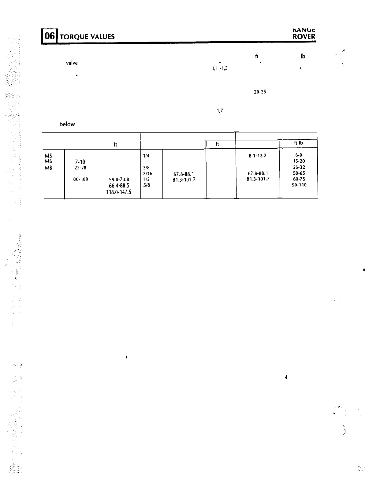
belciw
SIZE
MS
Mb
Ma
Ml0
Ml2
Ml4
Ml6
securing clamps
give torque values for all screws and bolts used except for those that are specified otherwise.
METRIC 1 SIZE
Nm
5-7 3.7-5.2
7-10 5.2-7.4
22-28 16.2-20.7
40-50 29.5-36.9
80-100
90-120
160-200
. . . . . . . . . . . . . . . . . . . . . . . . . . . . . . . . . . . . . . . . . . . . . . . . . . . . . . . . . . . . . . . .
ft
lb
59.0-73.8
66.4-88.5
118.0-147.5
l/4
5116
318
7116
l/2
518
Nm
6.8-9.5
20.3-27.1
35.3-43.4
67.8-88.1
81.3-101.7
122.0-149.1
UNC
t
L
1,7
ft
lb
5-7
15-20
26-32
SO-65
60-75
90-110
l-
20.3-27.1
35.3-43.4
67.8-88.1
81.3-101.7
122.0-149.1
f
Nm
8.1-12.2
UNF
!
15
I
.
J
. . .
/.
:
1
.?.
2
REVISED: SEPT. 90
Page 3
;^o”v’;l;
1987
TORQUE VALUES
.
..F.
.’
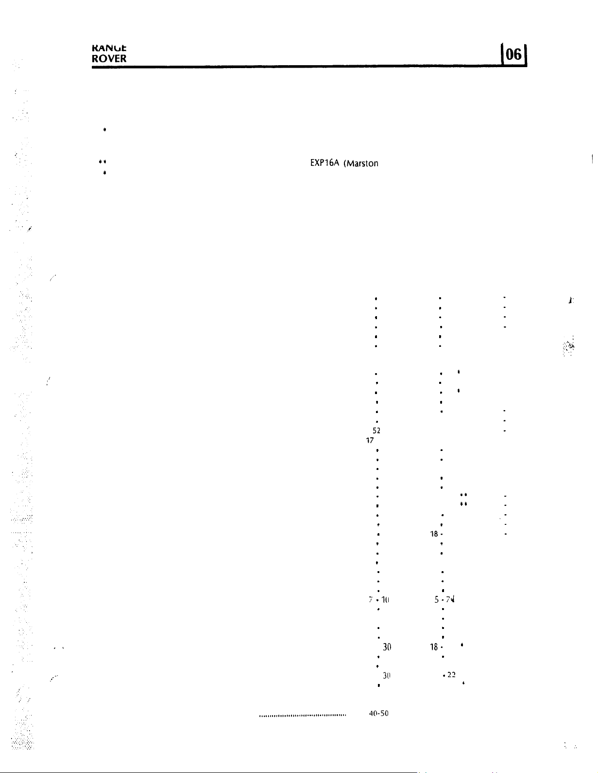
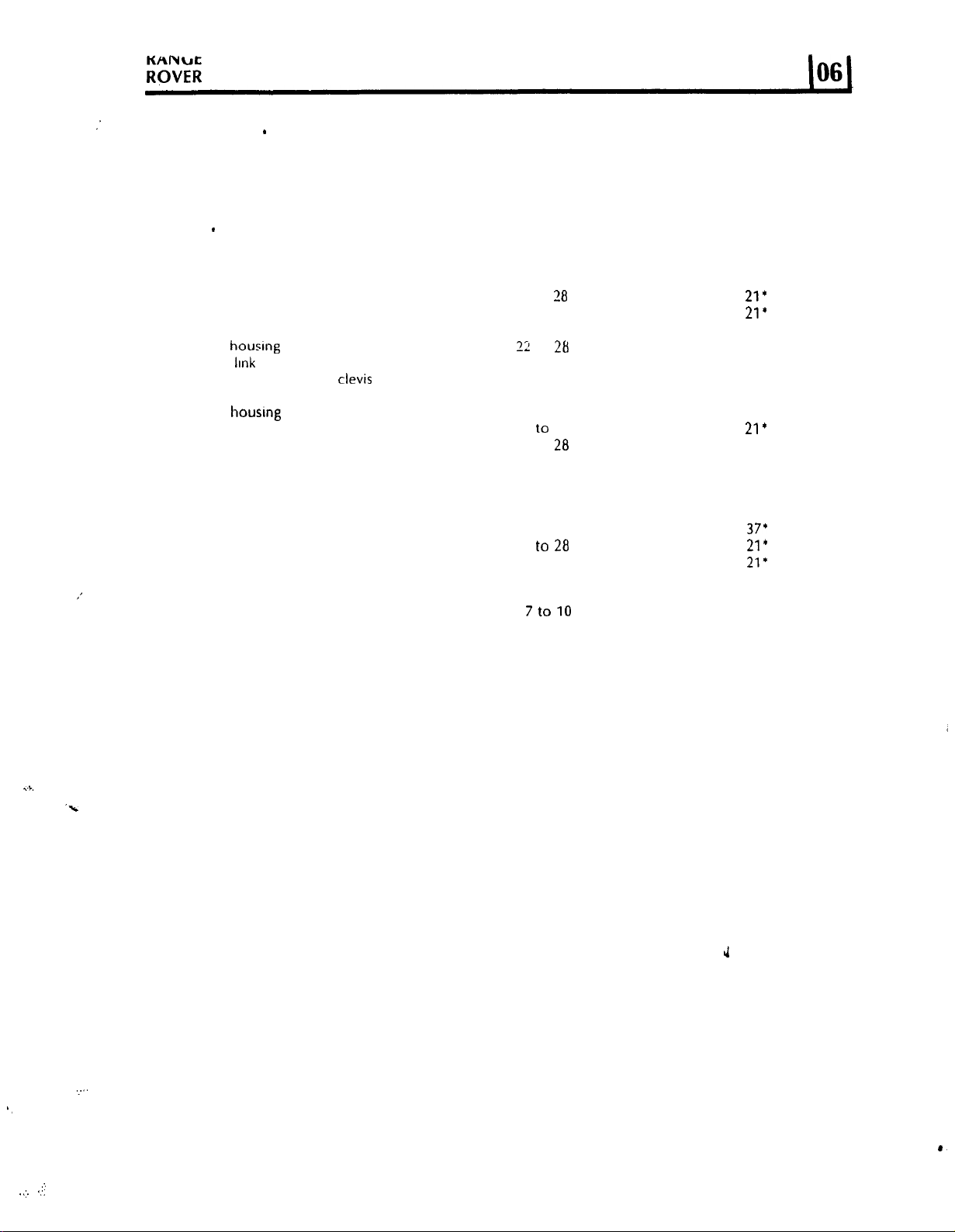
TORQUE VALUES - TRANSFER GEARBOX LT230
WARNING: Components in bold type must not be reused.
COMPONENT Nm ft lb
.........
...
Pinch bolt - operating arm to crank arm .........................
End cover gear change housing ......................................
Speedometer cable retainer
Rear
output/speedometer housing ..................................
Bottom cover to transler case
............................................
.........................................
Front output housing to transfer case .............................
Cross shaft housing to front output housing
Gear change
Pivot shaft to
Connecting rodtoadjustable
Anti-rotation
Front output
Pivot bracket to
housrng
IInk
plate
housrng
......................................................
arm .....................................................
clevis
................................
intermediate shaft ..............................
cover ............................................
extension housing .................................
..................
Finger housingtofront output housing ..........................
Bearing housing to transfer case .....................................
Brake drumtocoupling
flange ........................................
Bearing housing cover to transfer gearbox .....................
7 to 10
7
to 10
7
to 10
22 to 28
22 to 28
22 to 28
22 to 28
22 to 28
22 to 28
22 to
28
22 to 28
22t028
22 to 20
22 to 28
22 to 28
40
to 50
See note
5 to 7
5 to 7
5 to 7
16 to
21*
16 to
21’
16 to 21
16 to 21
16 to 21
16 to 21
16 to 21’
16 to 21’
16 to
21’
16 to 21’
16 to 21
16 to 21
29 to 37’
Rear output speedometer housing to
transfer gearbox
Selector finger to cross shaft high/low ............................
Selector
fork, high/lowtoshaft .......................................
Transmission
,’
Intermediate shaft stake nut .........................................
Gate plate
Plunger switch setting .....................................................
Gearbox
to
Gearbox to
Oil drain plug ..................................................................
Differential case (front to rear) ........................................
Output flanges ................................................................
Differential case rear stake nut ....................................
Oil filler/level plug ...........................................................
Transfer breather
..
.-%
Transfer box front drive flange to drive shaft ..................
Transfer box rear drive flange to drive shaft ....................
Transfer gearbox mounting brackets to chassis ...............
Mounting brackets to transfer gearbox ...........................
Mounting rubbers to
..............................................................
to speedometer housing
brake
to
grommet
plate
...........................................
..................
transfer case .................................................
transfer
case
.................................................
.............................................................
mounting brackets ........................
40
to 50
22t028
22 to 28
65 to
80
7to10
6.75 max
40 to 50
25 to 35
55 to
64
146to179
66 to
80
25 to 35
14 to
16
41 to
52
41 to
52
33 to 27
52
20 to 22
See text
See note
29 to
37’
16 to
21’
16 to
21*
48 to 59
5 to 7
4.82 max
29 to 37
19 to 26
40 to 47
108 to 132
50 to 59
19 to 26
10 to 12
30 to 38
30 to 38
24 to 20
38
13 to 16
NOTE: Studs to be assembled into casings with sufficient torque to wind them fully home, but this
torque must not exceed the maximum figure quoted for the associated nut on final assembly.
NOTE: ‘These bolts must have threads coated with Loctite 290 prior to assembly.
J
‘.“.
‘,
1
..I. ‘..
.>
REVISED: MARCH 90
Page 4

ZF4HP22
Coupling shaft to mainshaft ............................................
Filler tube to sump ..........................................................
Gear change lever to gearbox .......................................
Cooler pipe adaptor to gearbox ....................................
Securing screws - clutch
Securing screw - parking pawl .........................................
Securing screws -pump ..................................................
Intermediate plate plugs
Intermediate plate plugs
Bell housing mounting bolts
Governor mounting screws .............................................
Extension housing bolts
Control unit mounting bolts ...........................................
Sump plug .......................................................................
Mounting screws for sump ..............................................
Drive plate to converter ..................................................
Gearbox to engine ..........................................................
Strut (threaded end) ........................................................
Bottom cover to converter housing ................................
Cover - converter housing ..............................................
Drive
Adaptor to crankshaft
NOTE: *These bolts must have threads coated with Loctite 270 prior to assembly.
AUTOMATIC GEARBOX Nm
F
...............................................
(M20)
.......................................
(M14)
....................................... 40
........................................... 46
..................................................
plates to
crankshaft
adaptor
...................................................... 77 to 90
...................................
36
to 48
60 to 75
22 to 28
36 to 48
10
10
10
50
10
23
8
10
8
35 to 42
36 to 48
36 to 48
7 to 10
7 to
35
to 46
IO
ft lb
26 to 34’
45to 55
16 to 21
26 to 34
7
7
7
37
29
34
7
17
6
7
6
25to 30’
26 to 34
26 to 34
5 to
7
5 to 7
25 to
33’
55 to 65
FRONT AXLE Nm
Hub driving shaft to hub ................................................. 41 to 52
Brake disctohub ............................................................
Stub axle to swivel pin
Brake
caliper to swivel
Upper swivel pin to swivel pin housing ..........................
Lower swivel pin to swivel pin housing
Oil seal retainer to swivel pin housing ............................
Swivel bearing
Pinion housing
Crown wheel to differential
Differential bearing cap to pinion housing ......................
Differential drive flange to drive shaft .............................
Mudshield to bracket lower swivel pin ............................
Bevel
pinion nut ..............................................................
Draglink
Panhard
Radius arm to axle ........................................................... 190
Radius arm to chassis
Hub driving member to hub ........................................... 60 to 70
Stub
Oil seal retainer to swivel pin housing
rod to axle bracket
FRONT AXLE ABS VEHICLES
Brake disc to hub ............................................................
axle to
Brake caliper to swivel pin housing ................................. 75 lo 88
Upper swivel pin to swivel pin housing .......................... 60 to 70
Lower swivel pin to swivel pin housing..;;:
Swivel pin bearing housing to axle case .......................... 65 to 80
Disc shield .to bracket lower ............................................
housing
to axle case
to hub arm
swivel pin housing .......................................
housing
pin housing
to axle case
........................................................ 40
side member.. ............................... 190
.......................................
.................................
........................... 68 to 88
................................
.............................................
housing
............................................ 88
...............................
.:.
.................... 22 to 28
............................ 9 to
65 to 80
60 to 70
75 to 88
68 to 88
9 to 12
65 to 80
36 to
46
55 to 61
80 to 100
41
to 52
9 to 12
95 to 163
65 to 80
60 to 70
7 to 10
ft lb
30 to 38
48 to 59
44 to
52+
. . .
I
55 to 65
50 to
65’
50 to
65’
7 to 9
48 to 59’
26 to 34
40to45
59to 74
30 to 38
7 to 9
70to
120
30
65
140
140
44 to
52*
48 to 59’
44to 52.
55 to 65
’
44to 52
16 to
21’
I2
7 to 9
48 to 59’
5 to 7
NOTE: *These bolts to be coated with Loctite 270 prior to assembly.
2 REVISED: MARCH 90
Page 5

KMNU,f
ROVER
ls8’
TORQUE VALUES
REAR AXLE Nm
Axle shaft to hub .........................................................
Brake disc
Stub
Brake
Pinion housing to axle case ........................................
Crown
Differential bearing cap to pinion housing
Differential
Mudshield
Bevel pinion nut
Lower link to axle ........................................................
Pivot bracket
REAR AXLE ABS VEHICLES
Hub driving member to hub .......................................
Brake
Stub
Brake caliper io axle case ............................................
Disc shield
Sensor
NOTE: l These bolts to be coated with loctite 270 prior in assembly.
BORG WARNER TRANSFER GEARBOX
to
hub ........................................................
axle rear to axle case
caliper
to axle case
wheel to
disctohub ........................................................
axle rear to axle case
ring
differential
drive
flange to
to axle case
..........................................................
ball
joint
to axle case
to brake
..........................................
............................................
case
................................
..................
drive shaft .........................
...............................................
to axle
disc ............................................
....................................
..........................................
...............................................
41to 52
65 to 80
60 to 70
75to 88
36 to 46
55
to 61
80 to 100
41to 52
9 to 12
95
to 163
176
176 130
60 to 70
65 to 80
60 to 70
75
to
88
vto12
7 to 10
ft lb. in lb
30
to 38
48
to
59
44
to
52
55
to 65
26
to 34
40to 45
59to 74
30
to 38
7
to 9
70to 120
130
44
to
52’
48to59'
44
to 52
55
to 65
7
to 91
5
to 7
1)
,.
,’
. . .
Brake drum back plate to rear output
housing .......................................................................
Brake
drumtodrive
Centre differential (front
Centre differentialtosprocket ....................................
Drive flangestotransfer gearbox ................................
Drive
shaftstodrive flanges ........................................
Front cover to
Front
output housing
Gearbox
Mounting bracket
Neutral warning switch ................................................
Oil drain
Oil filler/level
Oil pump fixings.. ........................................................
Rear output housing
Selector lever shaft-Torx screw ...................................
Selector fork operating arm-Torx screw
CHARTS BELOW GIVE TORQUE
THAT ARE SPECIFIED OTHERWISE.
1
SIZE METRIC
mounting bracketstochassis .......................
plug ..............................................................
22-28
40-50
80-100
go-120
160-200
flange
..........................................
to rear)
rear cover-main
to main case
to gearbox
plug .......................................................
to main case
-i-
Nm
5-7
7-In
t
118.0-147.5
I
................................
case
...........................
.............................
.....................................
..............................
......................
SEl-FINGS
/SIZE
T
ft
lb
3.7-5.2
5.2-7.4
16.2-20.7
29.5-36.9
59.0-73.8
66.4-88.5
t
l/4
5116
318
7116
112
518
I
FOR ALL SCREWS AND BOLTS USED EXCEPT FOR THOSE
65-80
22-28
36-41
41-61
203-244
41-52
30-49
24-31
52
52
14-19
IV-30
IV-30
4-8.5
30-49
7-9
7-9
UNC
Nm
6.8-9.5
20.3-27.1
35.3-43.4/26-32 35.3-43.4
67.8-88.1
81.3-101.7
122.0-149.1
,!.-ft.lh
.
1
1
I
48-59
16-21
27-30
30-45
150-180
30-38
;;-;p
29-37
68-83
10-14
14-22
14-22
22-36
5-7
5-7
j
5-7
15-20 20.3-27.1 IS-20
50-65
60-75
9o-11o
- .**
35-75
60-84
60-84
II
Nm
8.1-12.2
6i.a-88.1
,
81.3-101.7
122.0-149.1 90-110
-
-.
UNF
fi
lb
6-9
26-32
50-65
60-75
/
REVISED: MARCH 90
3
Page 6

‘,
_.: ‘1:
,
:
.A’
.
. :
Page 7

PO;;;
1987
TORQUE VALUES
POWER STEERING BOX
Clamp bolt nuts ....................................................................
Ball joint nuts .......................................................................
Universal joint pinch bolt
Drop arm nut
Steering wheel
Sector shaft cover to steering box
Tie bar to steering box
Steering box to chassis ........................................................
Power steering pump mounting ...........................................
Pulley bolts, power steering pump
Union nut, inlet adaptor, power steering pump ...................
Steering column bracket nuts
FRONT SUSPENSION
Anti-roil bar front
-
Strap nyloc nuts .................................................................
-
Ball link self lock nut ..........................................................
-
Castellated nut
Drag link to axle ...................................................................
Securing ring for mounting turret
Radius arm to chassis
Panhard
Panhard
Panhard
Tie bar to
Radius arm to axle (front only)
.......................................................................
nut
...................................................................
rod mounting arm to chassis ..................................
rod to axle
rod to mounting bracket
Panhard
rod .........................................................
.....................................................
...............................................................
.......................................
.........................................................
....................................... 8-12
...............................................
.........................................
...........................................................
..............................................................
........................................ 88
............................................. 197
Nm
14 10
40
35
176 130
38 28
22 - 27
81
81
35
38 - 41 28 - 30
27 20
30
68 50
40
40
14 10
176 130
88
88
88
ft lb
30
26
16-20
60
60
26
6-9
22
30
30
65
65
65
65
145
in lb
REAR SUSPENSION
Anti-roll bar rear
-
Strap nyloc nuts
-
Ball link self lock nut
-
Castellated nut
Ball joint - levelling unit to rear axle
Top link to levelling unit .......................................................
Top link to mounting bracket
Upper joint to levelling unit
Lower joint to levelling unit .................................................
Bottom link to axle
Bottom link to chassis ..........................................................
Top link bracket to rear cross member ................................
Levelling unit to cross
Shock absorber to axle
BRAKES
Brake pipe connections to:
-
Brake calipers
- Jump
hoses to brackets .....................................................
- Jump
hose to three - way connection ...............................
-
Front caliper jump hoses
-
Rear caliper jump hoses
-
Jump hoses to calipers (all)
PDWA switch (AP type master cylinder)
Master cylinder to servo
(AP
type master cylinder
Brake caliper to swivel pin housing
Parking
Brake disc to hubs ................................................................
Bleed screws
brake
.................................................................
..........................................................
...................................................................
.....................................
...............................................
.................................................
...
............................................................
member ............................................
.........................................................
.....................................................................
....................................................
.....................................................
................................................
...............................
and
linkage to transfer box
.......................................................................
.....................................
servo)
......................................
...................................
30
68
40
176
115
176
34
34
176
176 130
47
47
37
12
11 - 13.5
12
11 - 13.5
11 - 13.5
12
1.4 - 1.7
13.6 - 17
75 - 88
26 - 32
65 -'80
9-
11
22
50
30
130
85
130
25
25
130
35
35
28
9
8 -10
9
8-10
8 -10
9
1 - 1.3
10 -
12.5
55 - 65
19-
24
48-
59
.;
80 -100
Continued
REVISED: SEPT. 90
Page 8

..
.:
.; :
Support plate and tube to valve body
Separator shell to valve body
Clamp ring to servo
Lucas
Cirling
Servo assembly
Brake pipes to master cylinder .............................................
Master cylinder to servo .......................................................
Bleed screws ........................................................................
Support plate and tube to valve body (servo)
Clamp ring to servo
Wabco
ABS system
Brake pipe connections to:
-
Hydraulic booster-Ml0
....................................................................................
- MI2
-
Calipers
- Fourway
- lump
-
lump
-
Hydraulic pump and accumulator
-
PCRV-Ml0
- PCRV -
-
Hydraulic booster to pedal box .........................................
-
Securing bolt, reservoir bracket
ROAD WHEELS
Wheel nuts
-
Alloy wheels . . . . . . . . . . . . . . . . . . . . . . . . . .
..............................................................................
connector rear axle
hose to brackets .......................................................
hose
Ml2
(AP
servo and master cylinder
to pedal
to valve
..............................................................
female
connectors ...........................................
.......................................................................
.......................................................................
(AP
type servo)
box
...............................................
................................................
L _
(AP
type
servo)
type servo) ......................
....................................
......................
...................................Separator shell body (servo)
..............................................
......................................
.........................................
.._..........................................
........
Nm
2-3
13.5 - 17
1 - 1.6
22 -
25
9-11
21 - 29
9-11
2-3
13.5 -
17
1 - 1.6
12 - 16
15 - 20
9-11
9-
11
11 - 13,s
11 - 13.5
12 - 16
11 -
13,5
12 - 14
22.5 - 27,5
9 - 11
122
-
129
ft
lb
16 - 19
7-8
15 - 22
9-12
11 - 15
7-8
7-8
8 -10
8 -10
9-12
8-10
9-10
17-20
7-8
90 - 95
in lb
16
-
20
120
-
150
10-15
80 - 100
16-20
120-150
IO-15
BODY
Front and rear seat belt fixings (ALL)
Front door hinges to door and body ...................................
‘.
Rear passenger door hinges to door and
Charts below give torque values for all screws and bolts used except for those that are specified
otherwise.
SIZE
MS
Mb
MB
Ml0
Ml2
Ml4
Ml6
METRIC
Nm
5-7 3.7-5.2 114
7-10 5.2-7.4 S/16 20.3-27.1
22-28 16.2-20.7
40-50 29.5-36.9
80-100
go-120
160-200
h
59.0-73.8 II2 81.3-101.7
66.4-88.5 518 122.0-149.1
118.0-147.5
....................................
lb
318 35.3-43.4 26-32
7116 67.8-88.1 50-65
body
SIZE
20.3
25
....................
Nm
6.8-9.5 5-7 8.1-12.2
25
UNC
ft lb
15-20 20.3-27.1
60-75 81.3-101.7
90-110
IS
19
19
Nm
35.3-43.4
67.8-88.1
122.0-149.1
UNF
ft lb
6-9
15-20
26-32
50-65
60-75
90-l IO
.:
REVISED: SEPT. SO
Page 9

PO;;;
1987
TORQUE VALUES
TORQUE VALUES 06
l-l
AIR CONDITIONING
Compressor hose .............................................................
Receiver drier hose ...........................................................
Receiver drier switch ........................................................
Compressor
oil filler
plug .................................................
Nm
34
to 40
14to21
21to25
8to12
ELECTRICAL
Alternator mounting bracket to cylinder head ..................
Alternator to mounting bracket ........................................
Alternator to adjusting link ...............................................
Alternator shaft nut .......................................................... 27.2 to 47.5
Alternator through bolts ................................................... 4.5 to 6.2
Alternator rectifier bolts ...................................................
Amplifier module screws ..................................................
Amplifier heat sink screws ................................................
Auxiliary driving
Distributor clampbolt
Drstributor prck-up bearing
Distributor pick-un barrel nuts .........................................
Drstrioutor
Spark
plug ........................................................................
Starter motor to engine bolts ........................................... 40.6 to 47.4
Starter motor through bolts ............................................. 6.2
Solenoid fixing screws ......................................................
Solenoid battery terminal nut ...........................................
Solenoid statter terminal nut ............................................ 3.2
Reverse light switch .......................................................... 20 to 27
Wiper motor yoke retaining bolts .................................... 1.35 to 1.8
lamp
vacuum
mounting bolts
.......................................................
plate support pillars .............. 1.0 to 1.2
unit
....................................................
.............................. 13.6 to 20.4
34
24
24
3.4
to 3.96
1.0 to
1.4
1 .O to 1.2
19to22
1 1toI.5
1.7to2.7
19
to 21.7
6.1
4
ft lb
24 to 29
10to15
15to19
6 to 9
25
17
17
20to 35
lot015
14 to 16
14 to 16
3oto 35
15to
20
in lb
4oto 55
30to
35
9to
12
9to11
9to11
10 to 12
15 to 24
55
55
35
28
12 to 16
Charts below give torque values for all screws and bolts used-except for those that are specified.
SIZE METRIC SIZE UNC UNF
Nm
MS
M6
M8 22-28
Ml0
Ml2
Ml4 go-120
Ml6 160-200
5-7 3.7-5.2 II4 6.8-9.5 5-7 8.1-12.2 6-9
7-10
40-50
80-100
ft lb
5.2-7.4 5116 20.3-27.1
16.2-20.7 318 35.3-43.4
29.5-36.9
59.0-73.8
66.4-88.5 518 122.0-149.1
118.0-147.5
7116 67.8-88.1
II2 81.3-101.7
Nm
ft lb
IS-20
26-32
SO-65
60-75
go-110
Nm
20.3-27.1
35.3-43.4
67.8-88.1
81.3-101.7
122.0-149.1
ft lb
15-20
26-32
SO-65
60-75
go-110
REVISED: DEC. 87
,,..
Page 10

74VIRE
I
BACK-UP
,A
CONNECTOR WIRING DIAGRAM
/
TO BATTERY
TO BRAKE
WACK)
(BLUE)
TO TRAILER
#6593B
PnntKl 1” u.5
A.
 Loading...