

Page 1

OWNER’S HANDBOOK
Publication Part No. LRL 10 02 56 901
Page 2

About this handbook
This handbook forms part of the Owner literature supplied with your new vehicle. Left-hand drive
and right-hand drive conditions may be shown in the graphics and where information is specific to
a particular country, it is indicated as such.
The Quick start section is designed to rapidly familiarise the driver with the initial set up and also
explain some of the unique features. Please take the time to study the operating instructions with
your vehicle as soon as you can.
Important
The information contained in this handbook covers all vehicle derivatives and optional equipment.
Some of the options may not be fitted to your vehicle unless they formed part of the original vehicle
specification. Therefore some parts of this handbook may not apply to your vehicle. Furthermore,
due to printing cycles, it may include descriptions of options before they become generally
available.
The information contained in this publication was correct when it went to print. Vehicle design
changes may have been made after this handbook was printed. When this occurs a handbook
supplement is added to the literature pack. Subsequent updates can be viewed on the Land Rover
Internet site at; www.ownerinfo.landrover.com.
In the interest of development, the right is reserved to change specifications, design or equipment
at any time without notice and without incurring any obligations. This publication, or part thereof,
may not be reproduced nor translated without our approval. Errors and omissions excepted.
© Land Rover 2007
All rights reserved.
Published by Land Rover Technical Communications.
2
Page 3

Quick start
REMOTE CONTROL .......................................... 7
ENGINE STARTING ........................................... 8
MASTER LOCK AND UNLOCK SWITCHES........ 9
TAILGATE ......................................................... 9
BONNET ............................................................ 9
POWER OPERATED SEAT ADJUSTMENT....... 10
DRIVING POSITION MEMORY ........................ 10
MANUAL SEAT ADJUSTMENT ........................ 11
WINDOWS AND DOOR MIRRORS .................. 11
STEERING COLUMN ADJUSTMENT ............... 12
STEERING COLUMN LOCK ............................. 12
OVERHEAD CONSOLE .................................... 12
SEAT BELTS AND CHILD RESTRAINTS .......... 13
PASSENGER AIRBAG DEACTIVATION............ 13
MANUAL CLIMATE CONTROL ........................ 14
AUTOMATIC CLIMATE CONTROL ................... 15
FACIA.............................................................. 16
INSTRUMENT PACK ....................................... 18
WARNING INDICATORS (ATTENTION) ........... 20
WARNING INDICATORS (INFORMATION)...... 20
WIPERS AND WASHERS ................................ 21
EXTERIOR LIGHTING ...................................... 21
GEARSHIFT INTERLOCKS............................... 22
AUTOMATIC TRANSMISSION......................... 22
CRUISE CONTROL .......................................... 23
HILL DESCENT CONTROL (HDC).................... 24
TERRAIN RESPONSE SYSTEM....................... 24
PARKING AID.................................................. 25
AUDIO SYSTEM .............................................. 26
RADIO OPERATION ........................................ 28
DAB RADIO ..................................................... 28
CD OPERATION .............................................. 29
SINGLE CD PLAYER ....................................... 29
CD AUTOCHANGER ........................................ 29
CLOCK SETTING ............................................. 30
TELEPHONE - BLUETOOTH SYSTEM.............. 30
Filling station information
FUEL FILLER FLAP.......................................... 32
TYRE PRESSURES.......................................... 33
ENGINE OIL SPECIFICATION .......................... 33
ENGINE COOLANT SPECIFICATION ................ 33
Introduction
SYMBOLS GLOSSARY ................................... 34
LABEL LOCATIONS......................................... 34
HEALTH AND SAFETY .................................... 35
DATA RECORDING ......................................... 36
DISABILITY MODIFICATIONS......................... 37
PARTS AND ACCESSORIES............................ 37
Keys and remote controls
USING THE KEY.............................................. 40
GENERAL INFORMATION ON RADIO
FREQUENCIES ................................................ 41
USING THE REMOTE CONTROL ..................... 41
Locks
LOCKING AND UNLOCKING ........................... 44
Alarm
ARMING THE ALARM ..................................... 45
DISARMING THE ALARM ............................... 46
Seats
SITTING IN THE CORRECT POSITION ............ 47
MANUAL SEATS ............................................. 48
ELECTRIC SEATS ........................................... 49
HEAD RESTRAINTS ........................................ 51
REAR SEATS .................................................. 51
HEATED SEATS .............................................. 53
Seat belts
PRINCIPLE OF OPERATION ............................ 54
SEAT BELT REMINDER .................................. 55
FASTENING THE SEAT BELTS ........................ 56
SEAT BELT HEIGHT ADJUSTMENT ................ 56
USING SEAT BELTS DURING PREGNANCY.... 57
Supplementary restraints system
PRINCIPLE OF OPERATION ............................ 58
AIRBAG WARNING LAMP .............................. 61
DISABLING THE PASSENGER AIRBAG........... 62
AIRBAG SERVICE INFORMATION................... 63
Child safety
CHILD SEATS ................................................. 64
BOOSTER CUSHIONS..................................... 67
3
Page 4

ISOFIX ANCHOR POINTS................................ 67
CHILD SAFETY LOCKS ................................... 69
Steering wheel
ADJUSTING THE STEERING WHEEL .............. 71
AUDIO CONTROL ........................................... 71
Lighting
LIGHTING CONTROL ...................................... 73
ADJUSTING THE HEADLAMPS FOR DRIVING
OVERSEAS ..................................................... 74
HEADLAMP LEVELLING ................................. 74
HAZARD WARNING FLASHERS...................... 74
ADAPTIVE FRONT LIGHTING SYSTEM (AFS). 75
DIRECTION INDICATORS ............................... 75
INTERIOR LAMPS .......................................... 76
APPROACH LAMPS ........................................ 76
CHANGING A BULB ........................................ 77
BULB SPECIFICATION CHART........................ 86
Wipers and washers
WINDSCREEN WIPERS .................................. 87
RAIN SENSOR ................................................ 87
WINDSCREEN WASHERS............................... 88
HEADLAMP WASHERS................................... 88
REAR WINDOW WIPER AND WASHERS........ 89
ADJUSTING THE WINDSCREEN WASHER JETS .
89
CHECKING THE WIPER BLADES .................... 90
CHANGING THE WIPER BLADES.................... 90
Windows and mirrors
ELECTRIC WINDOWS ..................................... 93
EXTERIOR MIRRORS ..................................... 94
ELECTRIC EXTERIOR MIRRORS .................... 95
ELECTRIC EXTERIOR MIRRORS WITH
POWERFOLD .................................................. 96
INTERIOR MIRROR ........................................ 96
Climate control
PRINCIPLE OF OPERATION .......................... 102
MANUAL CLIMATE CONTROL....................... 103
AUTOMATIC CLIMATE CONTROL ................. 104
HEATED MIRRORS ....................................... 106
AIR VENTS .................................................... 107
AUXILIARY HEATER...................................... 108
REMOTE CONTROL (Russia only)................. 108
ELECTRIC SUNROOF..................................... 109
Convenience features
CLOCK........................................................... 112
SUN VISORS ................................................. 114
CIGAR LIGHTER ............................................ 114
ASHTRAY ...................................................... 114
AUXILIARY POWER SOCKETS ...................... 115
CUP HOLDERS .............................................. 116
STORAGE COMPARTMENTS......................... 117
Starting the engine
GENERAL INFORMATION.............................. 119
STARTING A PETROL ENGINE ...................... 120
STARTING A DIESEL ENGINE ....................... 121
DIESEL PARTICULATE FILTER (DPF)............ 122
Transmission
MANUAL TRANSMISSION ............................ 124
AUTOMATIC TRANSMISSION....................... 124
TECHNICAL SPECIFICATIONS....................... 128
Brakes
PRINCIPLE OF OPERATION .......................... 129
HINTS ON DRIVING WITH ABS..................... 129
PARKING BRAKE........................................... 130
Parking aid
PRINCIPLE OF OPERATION .......................... 132
USING THE PARKING AID ............................. 133
Instruments
INSTRUMENT PANEL OVERVIEW .................. 98
Information displays
TRIP COMPUTER ......................................... 100
INFORMATION MESSAGES.......................... 100
Driving hints
GENERAL DRIVING POINTS.......................... 134
REDUCED ENGINE PERFORMANCE .............. 134
RUNNING-IN ................................................. 134
ECONOMICAL DRIVING ................................ 135
4
Page 5

Cruise control
PRINCIPLE OF OPERATION .......................... 136
USING CRUISE CONTROL ............................ 136
CLEANING THE EXTERIOR ........................... 161
CLEANING THE INTERIOR............................ 162
REPAIRING MINOR PAINT DAMAGE............ 164
Terrain response
PRINCIPLE OF OPERATION .......................... 138
USING TERRAIN RESPONSE ........................ 138
Hill descent control (HDC)
PRINCIPLE OF OPERATION .......................... 142
USING HDC................................................... 143
Traction control
USING TRACTION CONTROL ........................ 145
Stability control
PRINCIPLE OF OPERATION .......................... 146
USING STABILITY CONTROL........................ 147
Fuel and refuelling
SAFETY PRECAUTIONS ................................ 148
FUEL QUALITY .............................................. 148
ALTERNATIVE FUELS FOR PETROL ENGINES.....
149
DIESEL ENGINED VEHICLES......................... 149
RUNNING OUT OF FUEL ............................... 150
FUEL CUT-OFF .............................................. 150
FUEL FILLER FLAP........................................ 151
REFUELLING................................................. 151
TECHNICAL SPECIFICATIONS ...................... 153
Load carrying
GENERAL INFORMATION ............................. 154
LUGGAGE ANCHOR POINTS ......................... 155
LUGGAGE COVERS ....................................... 155
Towing
TOWING A TRAILER ..................................... 157
LEVELLING ................................................... 158
ESSENTIAL TOWING CHECKS ...................... 158
RECOMMENDED TOWING WEIGHTS ........... 159
TOW BAR...................................................... 160
Vehicle care
CLEANING THE ALLOY WHEELS .................. 161
Maintenance
GENERAL INFORMATION ............................. 165
OPENING AND CLOSING THE BONNET........ 168
ENGINE COMPARTMENT OVERVIEW........... 169
ENGINE OIL CHECK ...................................... 170
ENGINE COOLANT CHECK............................ 171
BRAKE FLUID CHECK ................................... 173
POWER STEERING FLUID CHECK ................ 174
WASHER FLUID CHECK................................ 175
TECHNICAL SPECIFICATIONS ...................... 177
Vehicle battery
BATTERY WARNING SYMBOLS ................... 179
BATTERY CARE ............................................ 179
USING BOOSTER CABLES............................ 181
CHARGING THE VEHICLE BATTERY............. 182
CHANGING THE VEHICLE BATTERY............. 182
Wheels and tyres
GENERAL INFORMATION ............................. 184
TYRE CARE................................................... 185
USING WINTER TYRES ................................ 191
CHANGING A ROAD WHEEL......................... 191
TYRE REPAIR KIT......................................... 195
USING TRACTION DEVICES ......................... 200
TYRE GLOSSARY ......................................... 201
TECHNICAL SPECIFICATIONS ...................... 202
Fuses
FUSE BOX LOCATIONS................................. 203
CHANGING A FUSE....................................... 203
FUSE SPECIFICATION CHART ...................... 204
Emergency equipment
HAZARD WARNING FLASHERS.................... 212
WARNING TRIANGLE ................................... 212
Status after a collision
DRIVING AFTER A COLLISION ..................... 213
INSPECTING SAFETY SYSTEM COMPONENTS...
214
5
Page 6

Vehicle recovery
TOWING POINTS .......................................... 215
Rear towing eye access (vehicles fitted with the
sports styling pack) ...................................... 215
LASHING POINTS ......................................... 216
TRANSPORTING THE VEHICLE .................... 216
TOWING THE VEHICLE ON FOUR WHEELS.. 216
Vehicle identification
VEHICLE IDENTIFICATION PLATE ................ 218
VEHICLE IDENTIFICATION NUMBER (VIN)... 218
VEHICLE BUILD DATE PLATE (Australia only).....
218
Technical specifications
ENGINE SPECIFICATIONS ............................ 219
WEIGHTS...................................................... 220
DIMENSIONS................................................ 221
Type approval
DECLARATIONS OF CONFORMITY............... 223
Audio introduction
RADIO RECEPTION....................................... 226
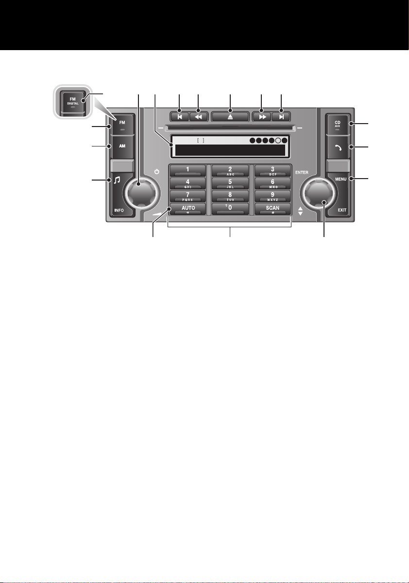
Audio unit overview
AUDIO UNIT OVERVIEW............................... 227
Audio unit operation
ON OR OFF CONTROL .................................. 231
VOLUME CONTROL ...................................... 231
AUDIO CONTROL ......................................... 231
WAVEBAND BUTTON ................................... 232
AUTOSTORE CONTROL ................................ 233
STATION PRESET BUTTONS ........................ 234
TRAFFIC INFORMATION CONTROL .............. 234
Audio unit menus
RADIO DATA SYSTEM (RDS) ....................... 236
REGIONAL MODE (REG) .............................. 236
ENHANCED OTHER NETWORK (RDS-EON).. 237
ALTERNATIVE FREQUENCIES ...................... 237
NEWS BROADCASTS ................................... 238
PRIORITY PROGRAMME TYPE (PTY) .......... 239
RESETTING THE AUDIO UNIT ...................... 241
Digital audio broadcasting
GENERAL INFORMATION.............................. 242
AUDIO CONTROLS ........................................ 244
DISPLAY OPTIONS ....................................... 245
SELECTING DAB ........................................... 245
CHANNEL AUTOMATIC TUNING ................... 245
ENSEMBLES.................................................. 246
CHANNEL OPTIONS ...................................... 246
PRESET BUTTONS ........................................ 248
SETTINGS ..................................................... 249
Compact disc player
LOADING COMPACT DISCS.......................... 255
EJECTING COMPACT DISCS ......................... 256
EJECTING MULTIPLE COMPACT DISCS ....... 256
COMPACT DISC SELECTION......................... 256
COMPACT DISC PLAYBACK.......................... 256
TRACK SELECTION ....................................... 256
COMPACT DISC PAUSE ................................ 256
FAST FORWARD/REVERSE ........................... 257
COMPACT DISC FUNCTION MENU ............... 257
COMPACT DISC DISPLAY OPTIONS ............. 257
SHUFFLE/RANDOM ....................................... 257
REPEAT COMPACT DISC TRACKS ................ 258
COMPACT DISC TRACK SCANNING.............. 258
MP3 FILE PLAYBACK.................................... 259
Auxiliary input (AUX IN) socket
AUXILIARY INPUT (AUX IN) SOCKET ........... 260
Rear passenger controls
REAR SEAT CONTROLS ................................ 262
HEADPHONES ............................................... 263
Telephone
GENERAL INFORMATION.............................. 264
TELEPHONE CONTROLS............................... 265
BLUETOOTH SETUP ...................................... 266
TELEPHONE SETUP ...................................... 269
USING THE TELEPHONE ............................... 272
PHONEBOOK................................................. 277
TELEPHONE VOICE CONTROL ...................... 281
6
Page 7
Quick start
6
3
1
E83183
2
7
4
5
Quick start
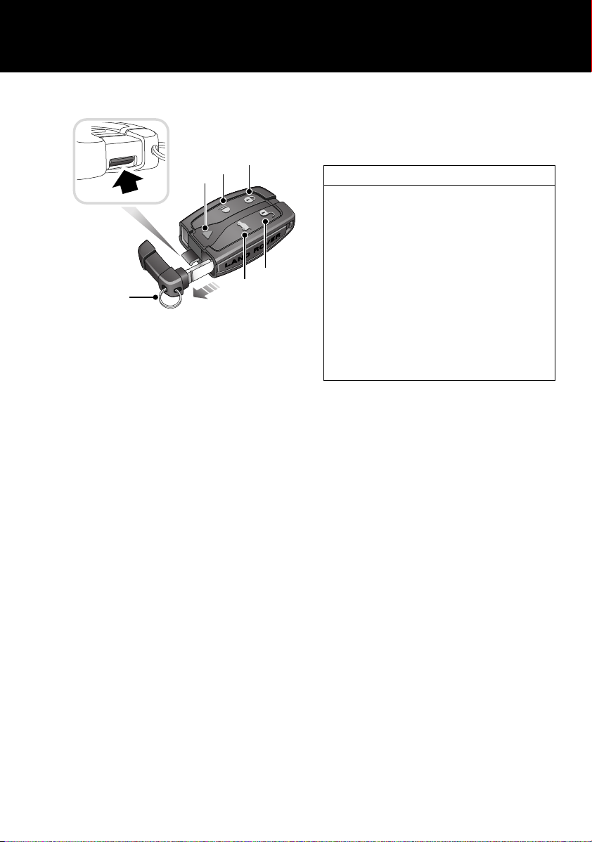
REMOTE CONTROL
1. Lock button.
• Press once to lock the vehicle and arm
the alarm. Press twice within three
seconds to double lock the vehicle.
Press and hold to close the door
windows (Global closing).
2. Unlock button.
• Press once to disarm the alarm, unlock
the driver's door and unlock the tailgate.
Press again to unlock the passenger
doors. Press and hold to open the door
windows (Global opening).
3. Approach lighting button.
• Press once to switch the headlamps,
position lamps, and license plate lamps
on for a short period. Press again to
switch off. See APPROACH LAMPS
(page 76).
4. Tailgate release.
• Press to release the tailgate.
5. Panic alarm.
• Press twice in three seconds, to activate
the panic alarm. After five seconds,
press twice within three seconds to
cancel the alarm.
6. Press the release tab on the remote control
to release the emergency key blade.
7. Pull the keyring attachment to remove the
key blade.
Single point entry
This is a security feature that unlocks only the
driver’s door, fuel filler flap, and tailgate. It
can be disabled on individual remote controls
by unlocking the vehicle then simultaneously
pressing and holding the lock and unlock
buttons for three seconds. The vehicle will
lock and then unlock in the currently selected
mode and the hazard warning lights will flash
twice to confirm the change.
You can now unlock all doors with a single
press. Repeating the procedure will re-enable
Single point entry.
Further information is available within the main
body of the handbook. See USING THE
REMOTE CONTROL (page 41).
7
Page 8
Quick start
1
EXT C
23
EXT F
72
EXT C
21
EXT C
23
EXT F
72
EXT C
21
1
1
2
2
E83184
2
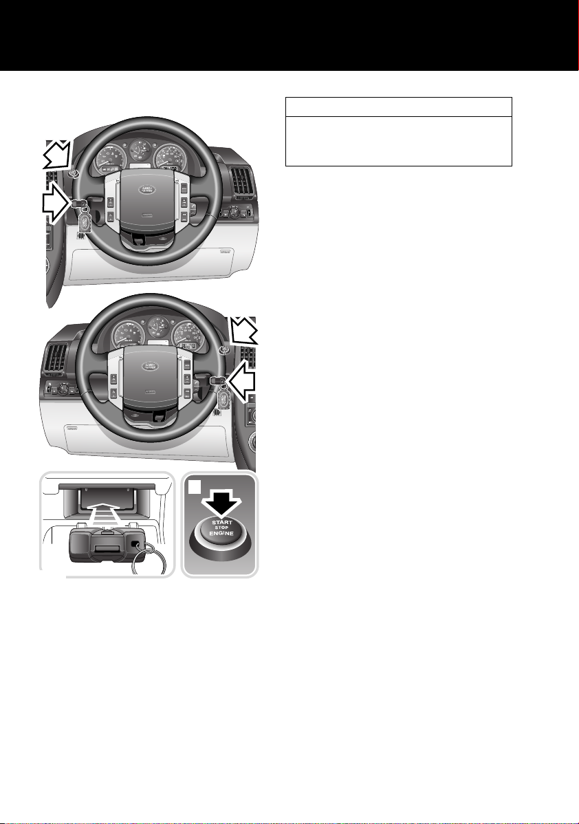
ENGINE STARTING
The START STOP ENGINE button 2 is only
operational when a recognised remote control
is inserted (docked) into the starter control unit
1 (buttons facing upwards).
Insert the remote control into the docking port
(buttons facing upwards) and press to latch. To
remove, press the remote control to unlatch
and release.
Remote control unit removal
Press the remote control to unlatch and
release from the starter control unit. Remove
by gripping the sides of the remote control.
Ignition only
• Press and hold the START STOP ENGINE
button until the warning indicators
illuminate, to switch on the ignition.
• Pressing the button again will switch off
the ignition.
Engine start/stop
• For automatic transmission vehicles, with
the gear selector in P (park) or N (neutral)
and the brake pedal depressed firmly,
briefly press and release the START STOP
ENGINE button to start the engine.
• For manual transmission vehicles, fully
depress the clutch pedal and briefly press
and release the START STOP ENGINE
button to start the engine.
• Press the button again to stop the engine
and switch off the ignition.
Note: Diesel vehicles may experience a delay
between pressing the start button, and the
engine starting when operating in cold
conditions. This is due to the extra time
required for the glow plugs to reach operating
temperatures. During this delay period the
clutch pedal (manual transmission) or brake
pedal (automatic transmission) must remain
depressed.
8
Page 9
Quick start
1 2
E83185
E83186
1
2
3
E83187
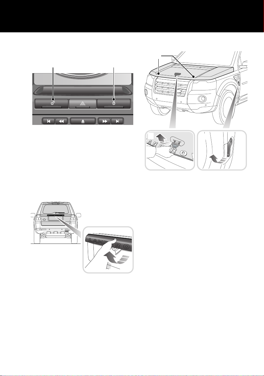
MASTER LOCK AND UNLOCK
SWITCHES
1. Press and hold to unlock all doors and
tailgate.
2. Press and hold to lock all doors and
tailgate.
Press and hold both buttons for three seconds
to release the tailgate.
TAILGATE
BONNET
Opening
Pull the bonnet release lever 1.
Lift the bonnet safety catch lever 2, and raise
the bonnet.
Closing
Lower the bonnet until the safety catch
engages. Using both hands, press the bonnet
down until the catches click.
Check that both catches 3 are engaged by
trying to lift the front edge of the bonnet.
With the vehicle unlocked, press the release
switch on the underside of the exterior handle
and pull to open.
9
Page 10
Quick start
12
4
3
LAN1050
LAN1052
12
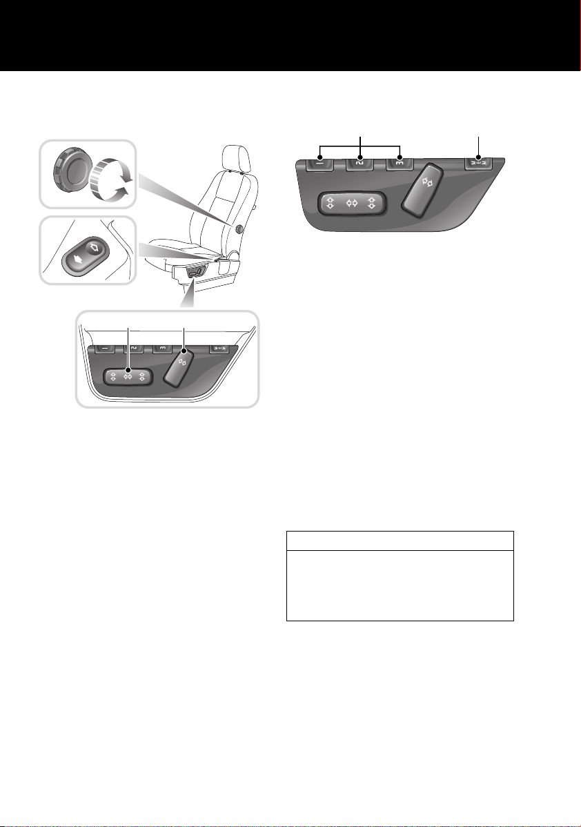
POWER OPERATED SEAT
ADJUSTMENT
1. Backrest adjustment switch.
2. Seat forward/backwards, cushion height
and cushion tilt control switch.
3. Lower backrest lumbar support
handwheel.
4. Lower backrest lumbar support switch.
Wherever possible the seats should be
adjusted with the engine running. In addition,
the seats have an active period that is initiated
when the driver’s door is opened and closed or
the remote control is removed from the
docking port.
DRIVING POSITION MEMORY
Once you have adjusted the power operated
driver's seat and exterior mirrors for your ideal
driving position, the vehicle can memorise
these settings for future use.
Make sure the remote control is in the docking
port and the ignition on.
1. Press the memory store button to activate
the memory function.
2. Press one of the preset buttons within five
seconds to memorise the current settings.
MEMORY STORED will be displayed on the
message centre accompanied by an
audible chime to confirm the settings have
been memorised.
3. To recall a stored position press the
relevant preset button.
Operating note
A seat position will only be memorised during
the five second active period.
Any existing settings will be over-written
when programming a memory position.
10
Page 11

Quick start
3
2
1
LAN1051
LAN1677
MANUAL SEAT ADJUSTMENT
1. Forward/backward adjustment.
2. Height adjustment.
3. Backrest adjustment.
WINDOWS AND DOOR MIRRORS
To operate the windows and door mirrors, the
remote control must be in the docking port and
the ignition on.
• To close the window, pull the switch up to
the first position.
Window movement can be stopped at any time
by releasing the switch.
The windows have a one touch facility that
allows them to be fully opened or closed with a
single operation of the switch. Press or pull the
switch fully to the second position and release.
Movement can be stopped by briefly pressing
the switch again.
Press switch 2 to inhibit the operation of the
rear window switches.
Note: The rear windows do not open on
commercial models.
Resonance with lowered windows
If a resonance/booming sound occurs when a
window is open, lowering an adjacent window
about 25 mm (1 inch) will eliminate the
condition.
Door mirror adjustment
To adjust the mirrors, press the L (Left) or R
(Right) button to select the appropriate mirror.
Move the control knob 1 in any direction to
adjust the position of the mirror glass.
Windows
• To open a window, press the respective
switch to the first position.
Power fold mirrors
The mirrors can be electrically folded towards
the door for better clearance/protection.
Press the L and R buttons simultaneously to
fold/unfold the mirrors.
The mirrors may also fold automatically when
the vehicle is locked, and unfold when the
vehicle is unlocked.
Reverse automatic mirror dip
When reverse gear is selected, the door
mirrors will dip.
11
Page 12
Quick start
E83192
E83193LAN1683
1
2
The dip position of the door mirrors can be
personalised, by adjustment when reverse gear
is selected.
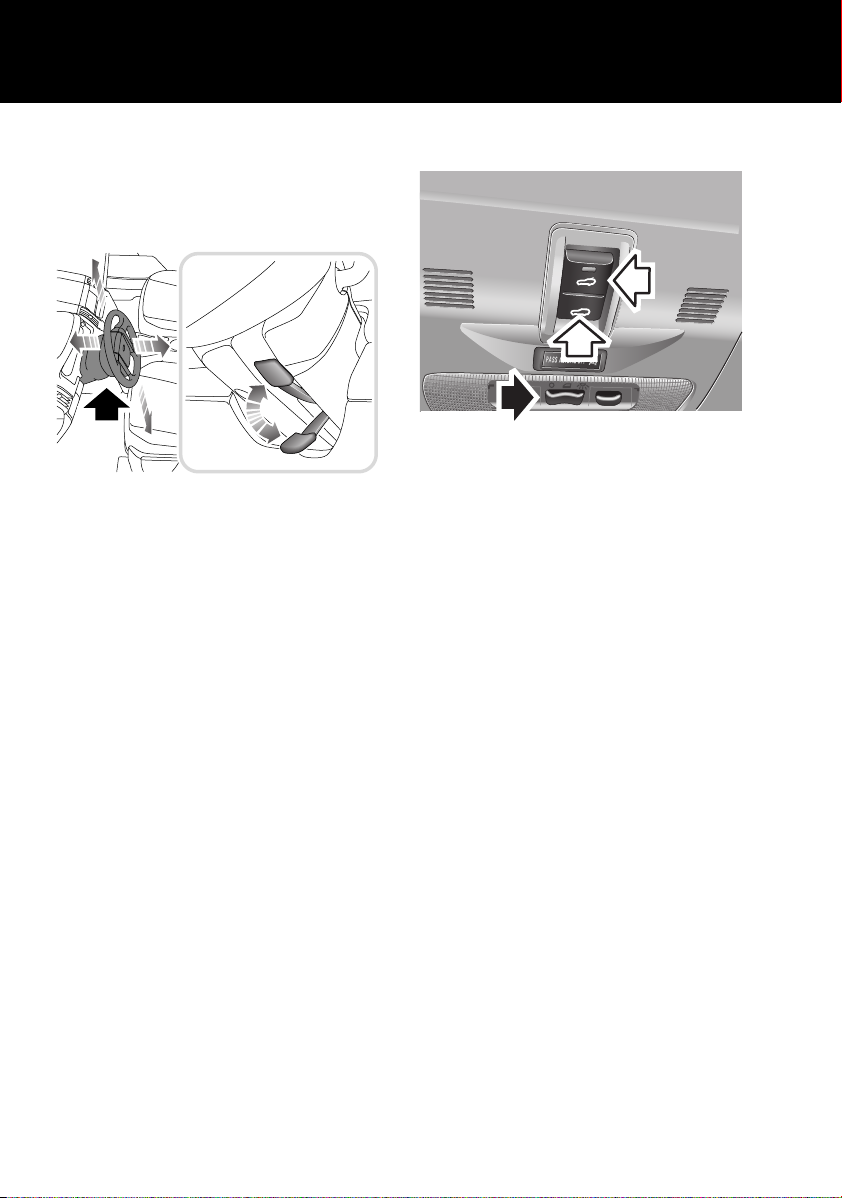
STEERING COLUMN ADJUSTMENT
1. Move the lever located under the steering
wheel fully downward.
2. Adjust the height and reach of the steering
wheel to the desired position.
3. Move the lever fully up to lock the position
of the wheel.
STEERING COLUMN LOCK
The vehicle has an electronic steering column
lock that is deactivated when the remote
control is inserted in the docking port.
Note: It may be necessary to rotate the steering
wheel slightly to release the locking
mechanism. If the steering column lock does
not disengage the engine will not start and
STEERING COLUMN LOCKED will be displayed
in the message centre.
OVERHEAD CONSOLE
Courtesy lamps
The front and rear courtesy lamps will operate
in conjunction with the vehicle being
unlocked/locked or when a door is opened.
The courtesy lamps can be manually switched
on or off by the lamp switch (arrowed in the
illustration). When the switch is in the centre
position, the lamps operate in automatic mode.
Panoramic sunroof
To tilt the sunroof:
• Press and release the front of the switch 2
to open the sunroof to the tilt position.
To open the sunroof:
• Press and release the rear of the switch 1
to fully open the sunroof.
To close the sunroof:
• From the fully open position, press and
release the front of the switch 2.
• From the tilted position, press and hold the
rear of the switch 1.
If the sunroof is moving, it can be stopped by
pressing the switch again.
12
Page 13
Quick start
LAN1684
Operating note
The sunroof can only be operated with the
ignition on.
SEAT BELTS AND CHILD
RESTRAINTS
A warning indicator on the
instrument pack will illuminate to
alert you that the driver's or front
passenger's seat belt is unbuckled.
Child seats
It is important to remember that the child's
weight, rather than age, determines the type of
seat that is required. See CHILD SEATS
(page 64).
Recommended child seat
Land Rover strongly recommend the use of
ISOFIX child seats.
ISOFIX child seats can only be fitted in the
rear outer seating positions.
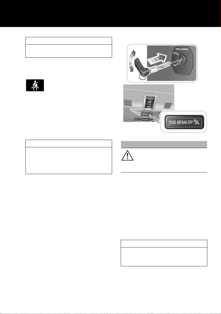
PASSENGER AIRBAG DEACTIVATION
WARNING
Do not use a child restraint on a seat
protected by an operational airbag in
front of it. There is a risk of death or
serious injury when the airbag deploys.
If it becomes necessary to fit a child restraint
on the front passenger seat, the passenger
airbag must be deactivated.
To deactivate the airbag, open the front
passenger door and use the starter key to turn
the PASS AIRBAG switch (located on the end of
the facia) to the OFF position.
With the airbag deactivated, the status
indicator, located on the overhead console, will
illuminate whenever the ignition is on.
Operating note
When an adult is seated in the front passenger
seat, ensure the PASS AIRBAG switch is
turned to the ON position.
13
Page 14
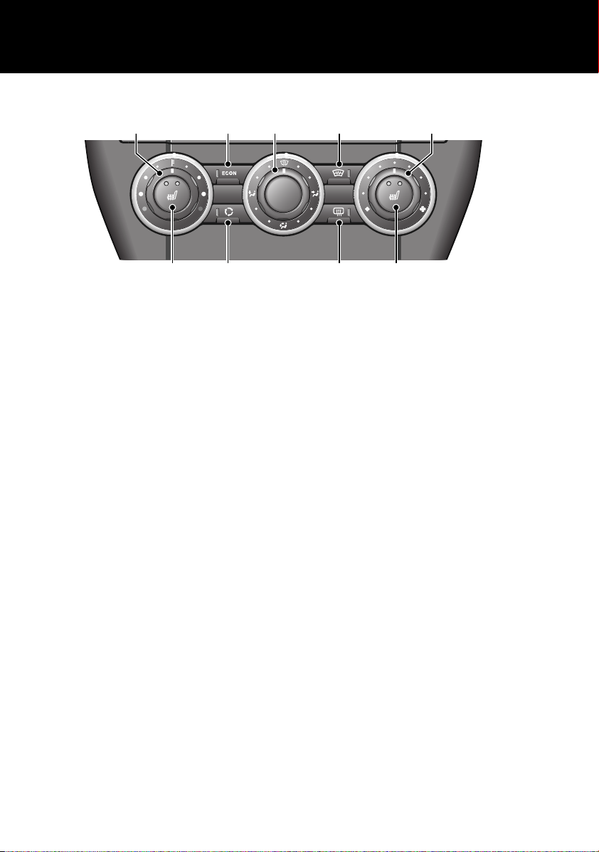
MANUAL CLIMATE CONTROL
E81418
1 2 3 4 5
8678
Quick start
1. Temperature control, rotate to adjust.
2. Economy mode, press to switch on/off.
3. Air distribution, rotate to direct air flow.
4. Heated front screen, press to switch
on/off.
5. Blower speed, rotate to change blower
speed.
6. Heated rear screen, press to switch on/off.
7. Recirculation, press to switch on/off.
8. Seat heaters, press to switch on/off. Press
once to turn on high, twice to turn on low,
and a third time to turn off.
Note: The amber tell-tale indicators in the
switches will illuminate when the function is
selected.
Economy mode (2)
When selected economy mode will achieve the
lowest possible temperature without using the
air conditioning system. This reduces power
consumption and improves fuel economy.
Air distribution (3)
Rotate the control to set the air distribution to
the required points. It is possible to distribute
air to two areas by selecting the point half way
between two symbols.
Note: In low temperatures it is advisable to
close the centre face level vent, and direct air
flow from the outer face level vents towards the
side windows. This will help to keep the
windows clear of ice.
Recirculation (7)
When selected, the air is recirculated inside the
vehicle. This helps to maintain a high or low
temperature, and is useful for preventing
fumes from entering the vehicle.
Note: Prolonged use at low temperatures may
cause the windows to mist.
14
Page 15
Quick start
LAN1111
1 3 1
69
2 54
1178
11
10
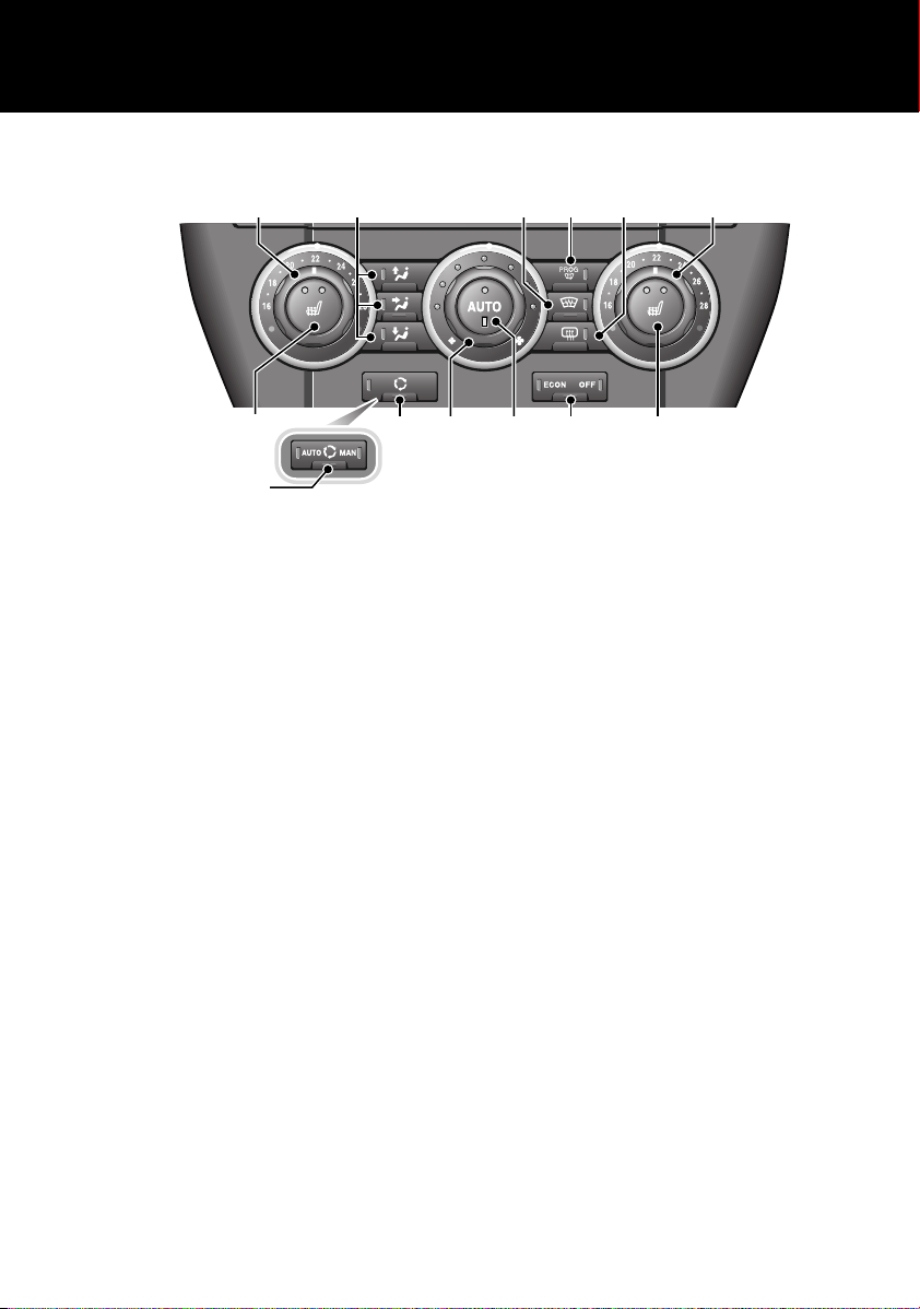
AUTOMATIC CLIMATE CONTROL
1. Left and right temperature controls, rotate
to adjust.
2. Air distribution. Press the relevant button
to set the air distribution to the required
points. Screen, face, or floor. It is possible
to select more than one option by pressing
the required combination of buttons.
3. Maximum defrost program, press to
switch on/off.
4. Heated front screen, press to switch
on/off.
5. Heated rear screen, press to switch on/off.
6. Economy mode/climate control system,
press repeatedly to toggle between:-
• Air conditioning on- LEDs off.
• ECON - Economy mode. Air conditioning
off.
• Off - Climate control system off.
7. AUTO mode, press to select fully
automatic operation.
8. Blower speed, rotate to change blower
speed.
In maual mode the current speed selection
is indicated by an illuminated LED.
9. Recirculation, press to switch on/off.
10. Air quality sensing, press repeatedly to
11. Seat heaters, press to switch on/off. Press
Note: The amber tell-tale lights in the switches
will illuminate when the function is selected.
Air distribution (2)
Note: In low temperatures it is advisable to
close the centre face level vent, and direct air
flow from the outer face level vents towards the
side windows. This will help to keep the
windows clear of ice.
toggle between:-
• Automatic - System automatically
selects fresh air, or recirculation,
depending on the levels of humidity and
pollution present.
• Manual - System locked to recirculation.
• Off - System locked to fresh air intake.
once to turn on high, twice to turn on low,
and a third time to turn off.
15
Page 16
FACIA
EXT C
23
EXT F
72
EXT C
21
100.72FM1
14 : 54
TA
NEWS
HEART FM
PTY
EXT C
23
EXT F
72
EXT C
21
9:10
AM
1 10 11
12
13
15
14
16
17
18
13
14
16
17
18
19
22
2
3
4 5 6 7
1
19
8 9
2
3
4
5
6
7
E83197
21 20
2120
Quick start
16
Page 17

Quick start
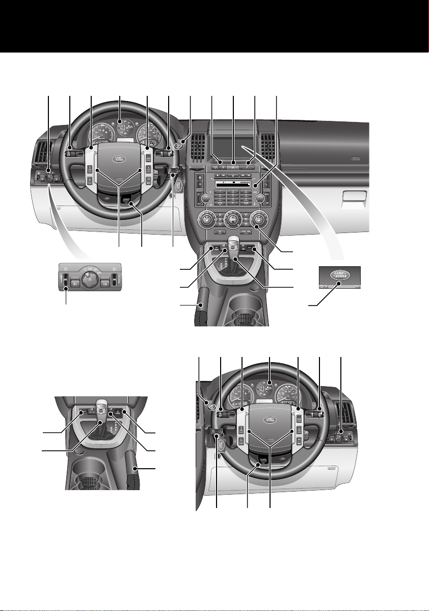
1. Exterior lamps master switch
2. Direction indicators/headlamps/trip computer switch
3. Cruise control switches
4. Instrument pack
5. Audio/telephone switches
6. Washer/wiper switch
7. Start stop engine button
8. Master unlock switch
9. Hazard warning switch
10. Master lock switch
11. Audio unit
12. Heater/air conditioning controls
13. Dynamic Stability Control (DSC) switch
14. Gear selector
15. Touch screen
16. Parking brake
17. Terrain Response control switch
18. Hill Descent Control (HDC) switch
19. Starter control unit
20. Steering column adjustment lever
21. Horn switches
22. Facia illumination dimmer control
17
Page 18

Quick start
EXT C
21
LAN1055
5678
1 42 3
9
INSTRUMENT PACK
1. Tachometer
2. Temperature gauge
3. Fuel gauge
4. Speedometer
5. Total distance (odometer) and trip recorder
6. Trip recorder reset switch
7. Gear selector mode and position display
8. Main message centre
9. Tachometer indicators panel
18
Page 19
Quick start
E80509
E80510
Tachometer
Indicates engine speed in revolutions per
minute (x 1 000). In normal driving conditions
the engine is most fuel efficient between 2 000
and 3 000 rev/min.
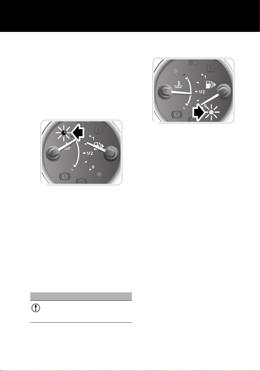
Temperature gauge
At normal operating temperature, the pointer is
positioned midway between the red and blue
segments of the gauge (the precise position
will vary according to climatic conditions).
If the pointer moves into the red segment and
the red warning indicator (arrowed)
illuminates, severe engine damage could occur
(under these circumstances the air
conditioning may switch off and engine
performance may reduce to minimise engine
load).
If the engine overheats, stop the vehicle as
soon as safety permits. Switch the engine off
and allow it to cool down. If the problem
recurs, seek qualified assistance before
continuing.
When the ignition is on the pointer quickly rises
to show the level of fuel in the tank.
When the amber low fuel warning indicator
(arrowed) illuminates, the remaining fuel
should give a range of 80 km (50 miles). The
small arrow alongside the fuel pump symbol
indicates the side of the vehicle on which the
fuel filler is located.
Total distance (odometer) and trip
recorder
Indicates the total distance travelled, and also
shows the distance travelled since the last
reset.
Trip recorder reset switch
With the ignition on, press to reset the trip
recorder back to zero.
Selected gear display
Displays the currently selected gear and
operating mode.
Fuel gauge
CAUTION
Never allow your vehicle to run out of fuel
as the resultant misfire may destroy the
catalytic converter.
19
Page 20
Quick start
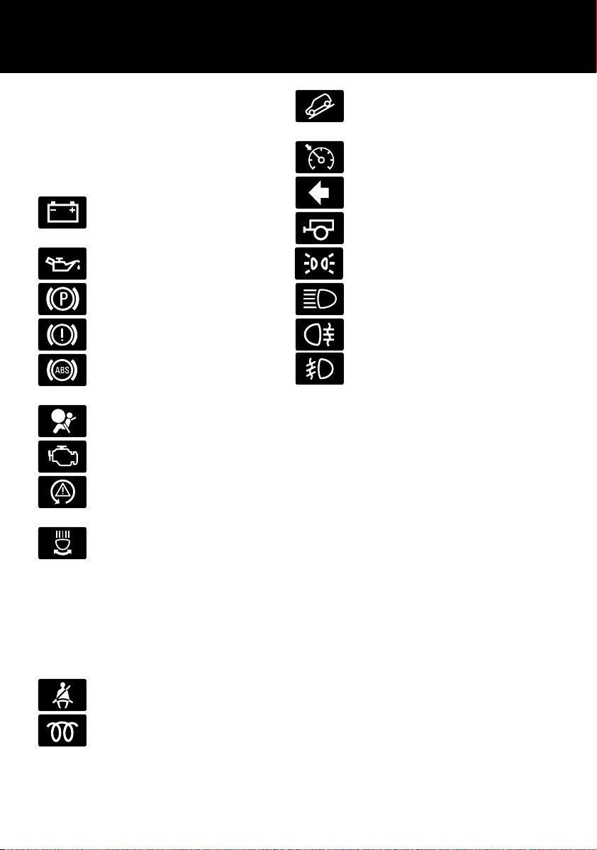
WARNING INDICATORS
(ATTENTION)
If any of the following illuminates whilst driving
a fault has been detected. Refer to the
individual pages given below for further
information.
Battery charge indicator. See
GENERAL DRIVING POINTS
(page 134).
Low oil pressure. See GENERAL
DRIVING POINTS (page 134).
Parking brake. See PARKING
BRAKE (page 130).
Brake systems. See PRINCIPLE OF
OPERATION (page 129).
Anti-lock braking system. See
HINTS ON DRIVING WITH ABS
(page 129).
Airbag system. See AIRBAG
WARNING LAMP (page 61).
Engine. See REDUCED ENGINE
PERFORMANCE (page 134).
Dynamic Stability Control (DSC).
See PRINCIPLE OF OPERATION
(page 146).
Adaptive front lighting system. See
ADAPTIVE FRONT LIGHTING
SYSTEM (AFS) (page 75).
Hill Descent Control (HDC) active.
See PRINCIPLE OF OPERATION
(page 142).
Cruise control active. See USING
CRUISE CONTROL (page 136).
Direction indicator. See DIRECTION
INDICATORS (page 75).
Trailer direction indicator. See
TOWING A TRAILER (page 157).
Side lamps on. See LIGHTING
CONTROL (page 73).
Headlamp high beam on. See
LIGHTING CONTROL (page 73).
Rear fog lamps on.
Front fog lamps on.
Information messages
Driver warning and information messages are
displayed in the message centre as required.
See INFORMATION MESSAGES (page 100).
WARNING INDICATORS
(INFORMATION)
The following will illuminate during normal
driving to indicate that a particular system or
feature is operating.
Seat belt reminder. See SEAT BELT
REMINDER (page 55).
Diesel glow plugs active. See
STARTING A DIESEL ENGINE
(page 121).
20
Page 21
Quick start
5
6
7
3
2
1
4
E83198
78 6 5
1
2
3
4
E83200
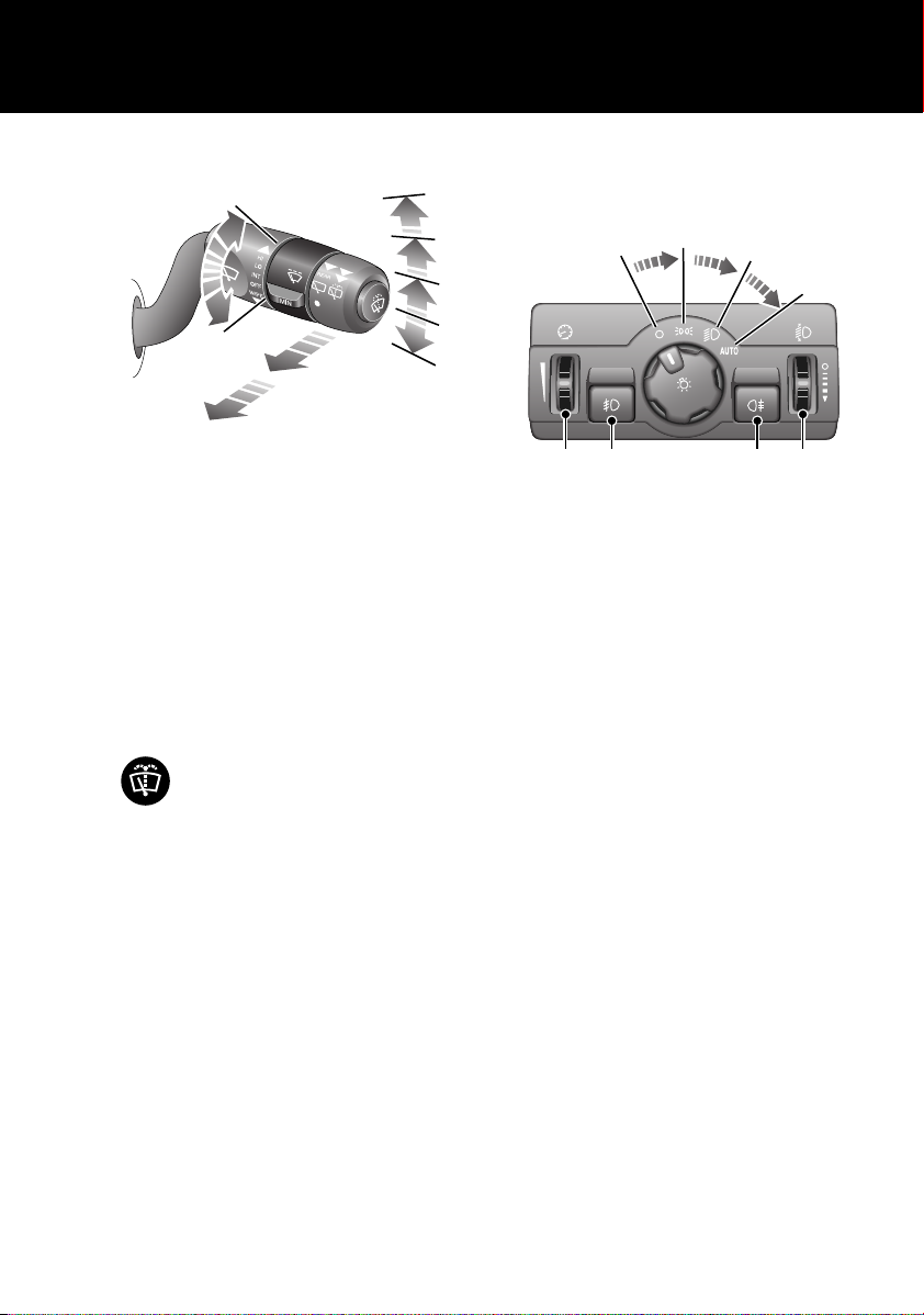
WIPERS AND WASHERS
Windscreen wipers
1. Intermittent wipe/rain sensor
2. Low speed wipe
3. High speed wipe
4. Single wipe - pull down and release to
operate
5. Rotate control to adjust speed of
intermittent wipe or sensitivity of rain
sensor
Windscreen washer
Push the button on the end of the
lever to operate the windscreen
washer.
Rear wiper and washer
Pull the lever to position 6 for intermittent
operation of the rear wiper. Pull and hold the
lever in position 7 to operate the rear washer
and wiper.
EXTERIOR LIGHTING
Exterior lamps master switch
1. Exterior lamps off
2. Side lamps
3. Headlamps
4. Autolamps
• With the switch in AUTO and the engine
running or ignition on, a sensor
monitors the exterior light levels and will
automatically switch the side lamps and
dipped headlamps on and off as
required.
5. Headlamp levelling control (Halogen
headlamps)
6. Rear fog lamps
7. Front fog lamps
8. Facia illumination dimmer control
21
Page 22
Quick start
E83199
E83201
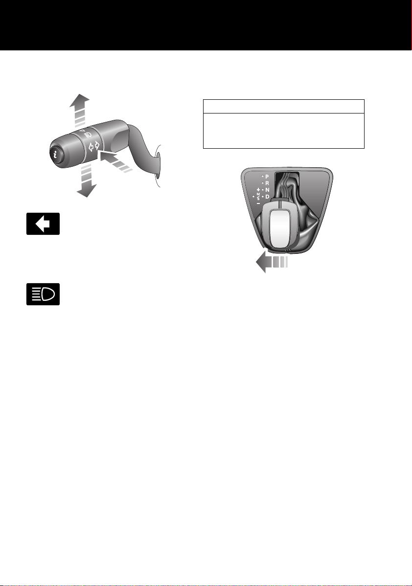
Direction indicators and headlamp high
beam
Move the lever up or down to
activate the direction indicators.
Moving the lever up or down against
spring pressure and then releasing will flash
the indicators three times. Useful for lane
changing.
Push the lever away from you to
select headlamp high beam. A
warning indicator will illuminate on
the instrument pack.
To flash the headlamps, pull the lever towards
the steering wheel and then release.
GEARSHIFT INTERLOCKS
Park
The remote control must be inserted in the
docking port, the footbrake applied and the
selector release button pressed before the gear
selector can be moved from P (Park).
AUTOMATIC TRANSMISSION
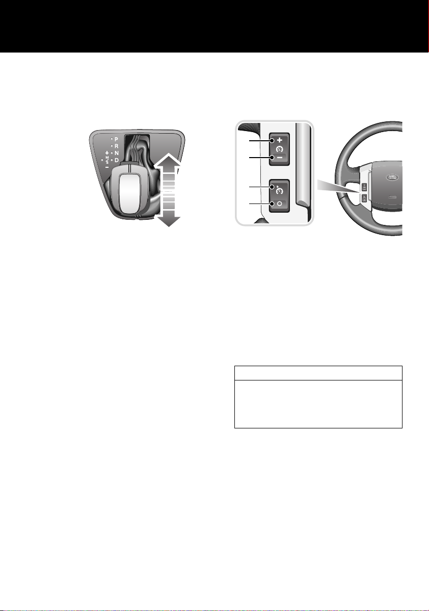
Sports mode
Operating note
If Terrain Response is fitted, Sports mode is
only available when the (Special programs
off) General program is selected.
In Sports mode, automatic gear changing is
maintained but the gearshift changes are
modified to improve performance.
To select Sports mode, move the gear selector
from the D position towards the left-hand side
of the vehicle.
The word SPORT will appear on the instrument
pack display and the LED in the gear selector
surround will illuminate.
Neutral
If the vehicle remains stationary with N
(Neutral) selected, the selector lever will lock
into the N position after 3 seconds.
Press the selector release button and apply the
footbrake to move the selector lever from N.
22
Page 23
Quick start
E83202
1
2
3
4
E83203
CommandShift™
CommandShift gear selection can be used as
an alternative to automatic gear selection and
is particularly effective when rapid acceleration
or engine braking are required.
• Select Sports mode. The transmission will
automatically select the gear most
appropriate to the vehicle's road speed and
accelerator position.
• Moving the selector lever forward (+) or
backwards (-) and then releasing will
manually select a higher or lower gear
(when available). The message
TRANSMISSION COMMANDSHIFT
SELECTED will appear in the message
centre.
• Subsequent gear selections will display the
selected gear on the instrument pack
display.
• To deselect CommandShift mode, move
the selector lever back to the D position.
CRUISE CONTROL
Cruise control enables the driver to maintain a
constant road speed without using the
accelerator pedal.
1. + : to set a road speed or increase the
speed in 2 km/h (1 mph) steps when cruise
control is operating.
2. - : to decrease the speed in 2 km/h (1 mph)
steps when cruise control is operating.
3. RESUME: resumes the SET speed retained
in memory.
4. CANCEL: cancels cruise control but retains
the set speed in memory.
Operating note
Cruise control will automatically disengage
when the brake/clutch pedal is used or when
the vehicle speed falls below 30 km/h (18
mph).
23
Page 24
Quick start
E83204
E83205
E80903
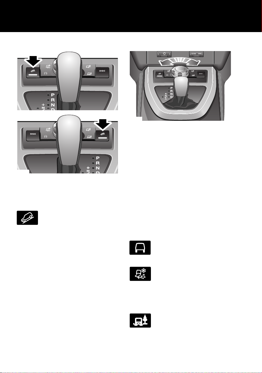
HILL DESCENT CONTROL (HDC)
HDC operates in conjunction with the anti-lock
braking system to provide greater control in
off-road situations particularly when
descending severe gradients.
Press the switch (arrowed in
illustration) to select HDC. HDC can
be selected at speeds below 80
km/h (50 mph) but will not be fully active until
the vehicle speed reduces below 50 km/h (30
mph), confirmed by a continuously illuminated
HDC indicator in the instrument pack. Press the
switch again to deselect HDC.
TERRAIN RESPONSE SYSTEM
The Terrain Response system, if fitted, is
always active and cannot be switched off.
When the vehicle is start ed the system will
normally start in the General (Special
programs off) program.
Manual selection of a special program, by
rotating the knob, will provide benefits in how
the vehicle can be driven over different
surfaces or terrains by automatically adjusting
the vehicle's systems.
It is recommended that a special program be
engaged whenever driving conditions could
become difficult, and cancelled once the
conditions for use are no longer present.
General (Special programs off)
Suitable for surfaces that match
typical road surfaces.
Grass-Gravel-Snow
Suitable for surfaces which are firm
but have a slippery surface, e.g.
grass, snow, loose gravel, pebbles,
or icy conditions. If the gravel is deep, the Sand
program may be more beneficial.
Mud-Ruts
Suitable for soft, muddy, uneven or
deeply rutted ground.
24
Page 25

Quick start
E93867
Sand
Suitable for soft, predominantly dry,
yielding sandy ground, e.g. sand
dunes and deserts. If the sand is
damp or wet the Mud-Ruts program may be
more beneficial.
Wading
When wading through water, select the
program suitable for the surface beneath the
water.
The maximum depth of water should not
exceed 500 mm (19.7 inches).
PARKING AID
With the ignition on, the front and rear parking
sensors are activated whenever reverse gear is
selected. A short confirmation tone will sound
after one second.
If an obstruction is detected by the sensors, an
intermittent tone will sound (higher pitch for
objects detected by the front sensors). As the
vehicle moves closer to the obstruction the
intermittent tone increases in frequency.
When the distance between the sensor and the
obstruction is less than approximately 30 cm
(1 foot) the tone becomes continuous.
The parking aid is automatically switched off
when the vehicle's forward speed exceeds 16
km/h (10 mph).
Front parking aid - manual operation
When driving into a limited space, the front
parking aid can be manually activated by
pressing the switch on the facia. The switch
will illuminate and a short confirmation tone
will sound.
25
Page 26
AUDIO SYSTEM
BBC R42
FM1 14 : 54
TA NEWSPTY
E84421
7
321
9
4
567
6 8
10
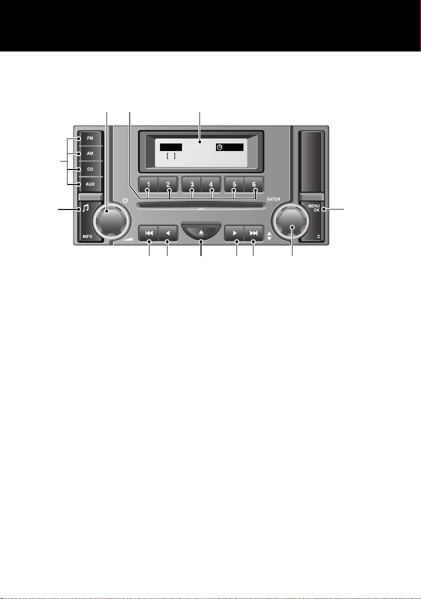
Standard audio
Quick start
1. Press to switch audio unit on or off and
rotate to adjust the volume.
2. Press appropriate number to select
required preset radio station or disc from
autochanger.
3. Display screen.
4. Press to access the audio unit menu.
5. Rotate to scroll through menu options or
adjust settings. Press to select a menu
item or confirm a change.
6. Press to automatically search for a radio
station or select a track on a CD.
7. Press to manually search for a radio
station or to search in a CD track
8. Press to eject the currently selected CD.
9. Press button repeatedly to scroll through
the sound settings options. With the
desired sound setting selected, rotate
control 1 to adjust. Confirm new setting by
pressing button 9.
10. Press the appropriate mode button to
select FM, AM, CD or AUX.
26
Page 27
Premium audio
TA
NEWS
PTY
100.7FM1
14 : 54HEART FM
1234 62
LAN1687
3 4 5 4 3
6
7
8
21
91011
12
13
14
15
Quick start
1. Press to switch audio unit on or off and
rotate to adjust the volume.
2. Display screen.
3. Press to automatically search for a radio
station or select a track on a CD.
4. Press to manually search for a radio
station or to search in a CD track
5. Press to eject the currently selected CD.
6. Press to select CD.
• Press the CD button to change between
CD and AUX input.
7. Telephone button.
8. Press to access the audio unit menu.
9. Rotate to scroll through menu options or
radio presets. Press to select a menu item
or confirm a change.
10. Press appropriate number to select
required preset radio station or disc from
autochanger.
11. Press and hold to automatically store AMa
and FMa radio stations. Press and release
to access the autostored stations.
12. Press button repeatedly to scroll through
the sound settings options. With the
desired sound setting selected, rotate
control 1 to adjust. Confirm new setting by
pressing button 12.
13. Press to select the AM radio frequency.
14. Press and release the FM button to change
between FM1 and FM2.
15. Press and release the FM/DAB button to
change between FM1, FM2, DAB1 and
DAB2.
27
Page 28
Quick start
1
2
3
4
E83208
LAN1114
FM1
Classic
100.3
Auto-tuning
50%
E88130
E85661
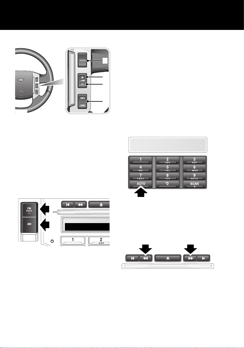
Steering wheel controls
1. Press to switch between Radio, CD, or
AUX.
2. Press to increase volume.
3. Press to decrease volume.
4. Press and release to scroll through preset
radio stations or CD tracks. Press and hold
for two seconds to search up or down for
the next radio station/CD track.
RADIO OPERATION
Storing radio stations
To automatically store radio stations, press
and hold either the FM or AM button on
standard audio units or the AUTO button on
premium audio units. The stations will be
stored under the preset numbers in the
selected waveband.
To recall a preset station, press and release one
of the numbered preset buttons.
A selection of radio presets can be stored
manually. See STATION PRESET BUTTONS
(page 234).
DAB RADIO
Press either the FM or AM button to select the
required waveband. Repeated presses of either
button will scroll through the FM and AM
waveband memory options.
On the premium audio unit, press and release
the FM button repeatedly until either DAB1 or
DAB2 is displayed. To automatically tune all the
available digital radio channels, press and hold
the AUTO button.
Use the channel search buttons to scroll
through the list of available channels. When
you find a channel you want to store, press and
hold a numbered preset button.
28
Page 29
Quick start
E88124
14 : 54
1234
DAB1 [1]
BBC 5LIVE
100.72FM1
14 : 54
TA
NEWS
HEART FM
PTY
E83211
Some channels can contain sub-channels. If
sub-channels are available, an arrow icon is
displayed. To access a sub-channel, press and
hold one of the channel search buttons. Press
and release the channel search button
repeatedly to scroll through the available
sub-channels. See CHANNEL OPTIONS
(page 246).
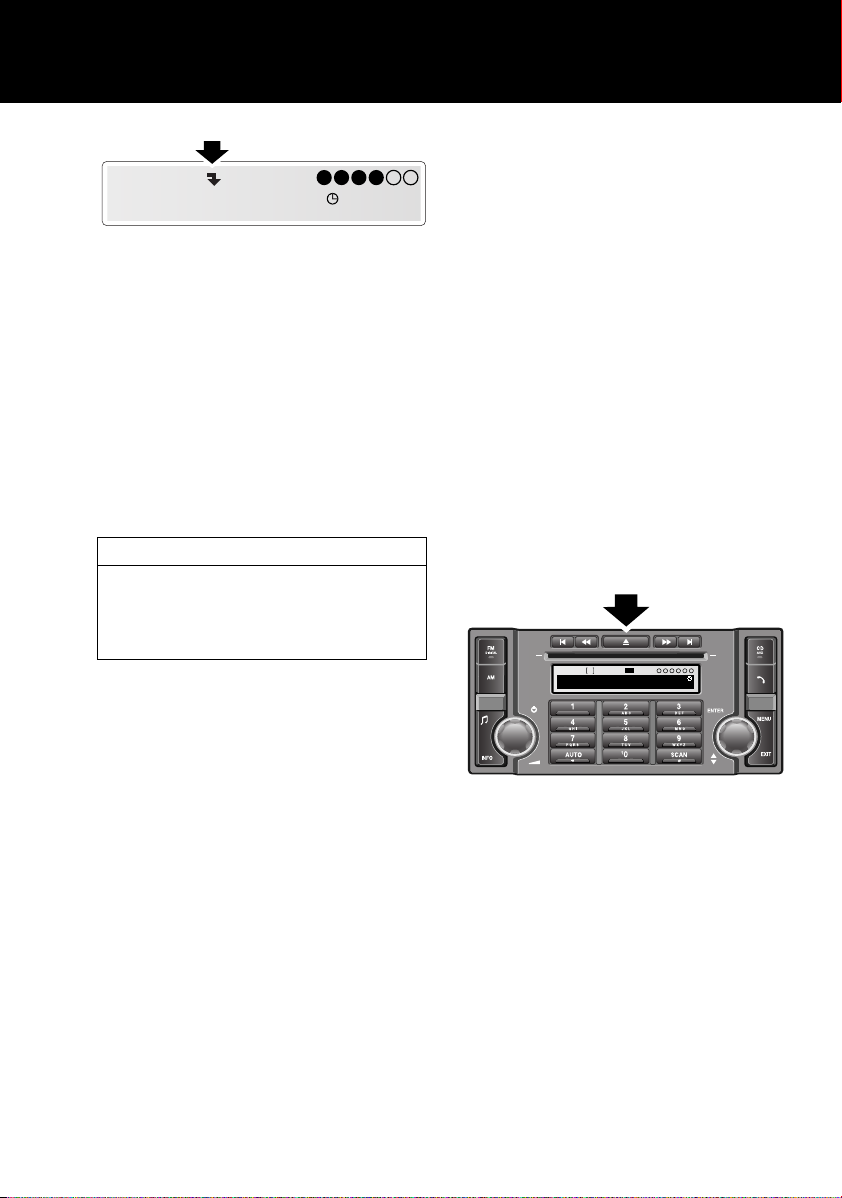
CD OPERATION
CD AUTOCHANGER
Loading CDs
To insert a single disc, press the CD button
then one of the number buttons (1 to 6). When
prompted by the information display, insert the
disc, label side up. The autochanger will load
the CD in the selected position.
Playing CDs
When in CD mode, press the appropriate CD
number (1 to 6) to start playing the selected
disc. Playback commences and progresses
sequentially through all of the loaded discs.
Playback can be paused by briefly pressing one
of the other mode buttons (FM or AM).
Playback will resume when the CD button is
pressed again.
Compatible disc types
The use of discs with paper labels or
double-sided dual format discs (CD/DVD)
should be avoided as they could become
jammed.
Depending on specification, your audio unit
will feature either a single-slot CD player or an
integral 6-disc autochanger.
SINGLE CD PLAYER
Insert a disc, label side up, into the player. The
disc will load and start to play.
To end CD playback, briefly press one of the
other mode buttons (FM or AM). Playback will
resume when the CD button is pressed again.
To eject the disc, press the eject button. When
prompted, remove the disc from the CD slot.
Ejecting CDs
To eject a single disc, select the required disc
by pressing one of the number buttons 1 to 6
and then press the eject button.
To eject all loaded discs, press and hold the
eject button, the discs will be ejected one at a
time. Remove disc only when the display
shows the message Remove Disc.
29
Page 30
Quick start
Clock
OK
06:15
Set
PM
E84423
CANCEL
SET
Time Set
PM 1:39
E84424
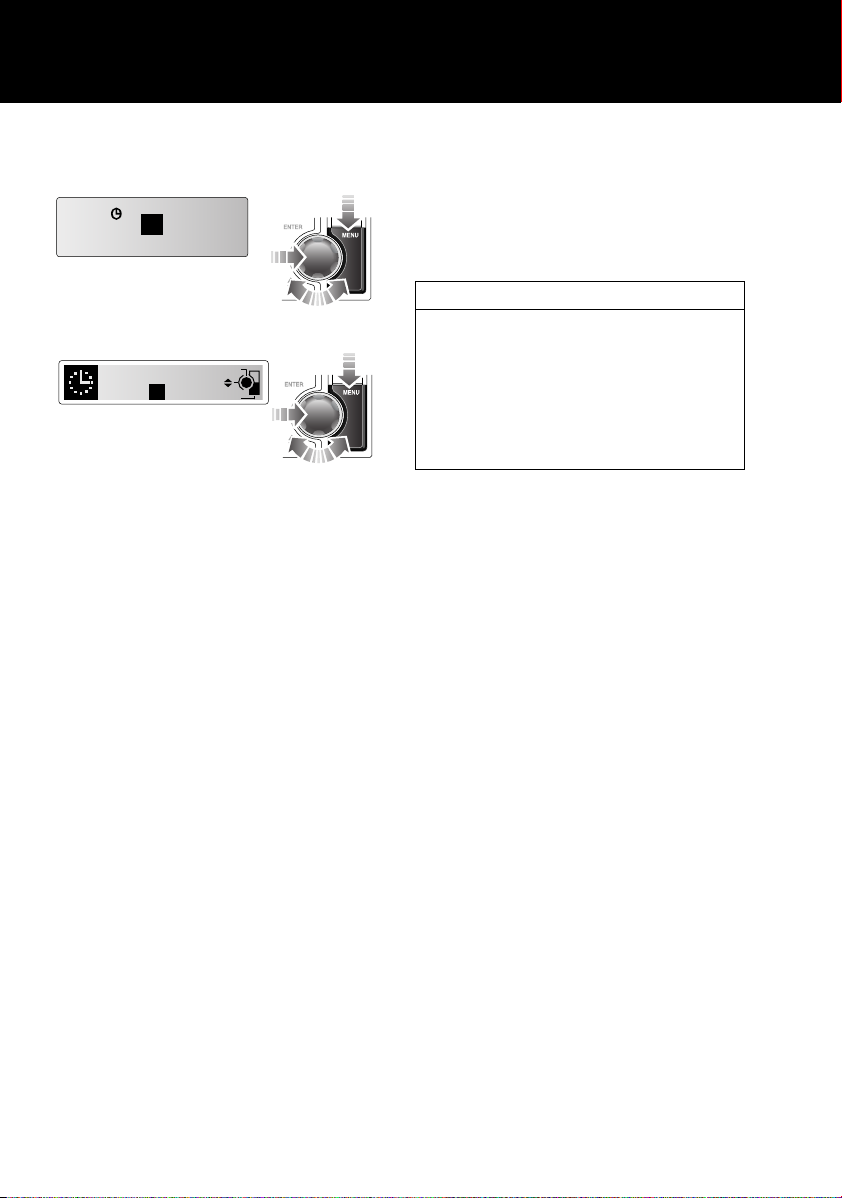
CLOCK SETTING
Standard audio
Premium audio
1. Switch on the audio system, by pressing
the volume rotary control.
2. Press the MENU button to access the
function menu.
3. Rotate the control to select Clock and
press to confirm selection.
4. On standard audio units, rotate the control
to select Set and press to confirm
selection.
5. Rotate the control to adjust the hour and
minutes. Press the control to confirm
setting after each action. On premium
audio units, the time mode (12 or 24 hr)
can also be set from this menu.
6. Once the time has been set, on standard
audio units, OK will be highlighted. Press
the rotary control to accept the settings.
Press the EXIT button on premium audio
units to cancel and return to the menu.
TELEPHONE - BLUETOOTH SYSTEM
Mobile phones with Bluetooth capability can
communicate with the vehicle’s inbuilt
telephone feature. You must pair your
Bluetooth mobile phone with the vehicle’s
system before use.
Mobile phone compatibility
Not all phones are fully compatible with the
Land Rover system. For the latest list of
compatible phones and software versions,
please refer to
www.ownerinfo.landrover.com.
Alternatively consult your Land Rover
Dealer/Authorised Repairer.
Pairing a phone to the vehicle's system
1. With the ignition on, press the telephone
mode button on the audio unit.
2. When prompted, press the ENTER control
to confirm that you want to pair a
telephone to the system.
3. The system will ask you to check that your
Bluetooth function on your telephone is
enabled. Press the ENTER control to
confirm. The system will then search for
your telephone.
4. After the search is completed, the detected
telephones will be listed. Rotate the ENTER
control to scroll through the list and press
to select the correct telephone.
5. The audio unit will then display a Bluetooth
access code number. Enter this number
into your telephone. The telephone will
now pair to the system.
6. If the pairing fails, a message will appear
on the audio unit display. Press the ENTER
control to retry or press the EXIT button
and restart the process.
30
Page 31

Quick start
1
2
E83216
7. To cancel the pairing process, press and
hold the telephone button on the audio
unit.
Operating note
If more than one paired Bluetooth phone is in
range, the system will automatically select the
last phone used in Bluetooth mode.
Making a call
1. With a paired handset, press the telephone
mode button on the audio unit.
2. Enter the required telephone number using
the numeric keypad.
3. Press and release the ENTER control or
operate the answer call switch 1 on the
steering wheel to send.
Receiving a call
To answer an incoming call, press and release
the ENTER control on the audio unit, or operate
the answer call switch 1 on the steering wheel
controls.
To end, or reject an incoming call, press and
release the EXIT button or operate the end call
switch 2 on the steering wheel controls.
31
Page 32

Filling station information
E83705
E83217
E83218
Filling station information
FUEL FILLER FLAP
Fuel filler flap location
A small arrow on the fuel gauge
indicates which side of the vehicle
the fuel filler flap is located.
Fuel filler flap opening
With the vehicle unlocked, pull the flap (as
arrowed in the illustration) to open.
Operating note
The fuel filler flap will not open if the vehicle is
locked.
Refuelling
Fuel tank capacity
Model Litres Gallons
Petrol engine 70 15.4
Diesel engine 68 14.9
Fuel specification
CAUTION
This vehicle is not suitable for use with
fuels containing more then10% Ethanol.
Do not use E85 fuels (85% Ethanol content).
Equipment necessary for the use of fuels
containing more than 10% Ethanol is not fitted
to this vehicle. If E85 fuels are used, serious
engine and fuel system damage will occur.
The correct fuel specification for your vehicle is
shown on the inside of the fuel filler flap. See
TECHNICAL SPECIFICATIONS (page 153).
CAUTION
Diesel vehicles in Algeria, Egypt, Libya,
Morocco, Pakistan and Tunisia must
only use premium diesel fuel.
Note: Land Rover vehicle's are capable of
running with up to a 5% blend of bio-diesel in
accordance with European Standard EN590.
The filler cap is secured to the vehicle by a
strap. For your convenience, a holder is
provided, on the fuel filler flap, to hook the
strap over while refuelling.
After refuelling, tighten the filler cap until it
clicks three times.
Incorrect fuelling
CAUTION
If the fuel tank is accidentally filled with
the wrong type of fuel, do not start the
engine. It is essential that you seek qualified
assistance.
32
Page 33

Filling station information
E83219
TYRE PRESSURES
Tyre pressure label
The correct tyre pressures are shown on a label
attached to the driver's door pillar.
ENGINE OIL SPECIFICATION
Model Specification
Petrol engine Use only 0W-30 engine
oil, meeting ACEA A5/B5
specification.
Diesel engine Use only 5W-30 oil
meeting Land Rover
WSS-M2C913-B
specification.
LAND ROVER RECOMMENDS
ENGINE COOLANT SPECIFICATION
Top-up to the upper level indicator mark. Use
only a 50% mix of water and Texaco XLC
antifreeze. See ENGINE COOLANT CHECK
(page 171).
33
Page 34

Introduction
E83651
E83652
Introduction
SYMBOLS GLOSSARY
Warnings
WARNING
Safety warnings are included in this
handbook. These indicate either a
procedure which must be followed
precisely, or information that should be
considered with great care in order to avoid
the possibility of personal injury.
Cautions
CAUTION
Cautions are included in this handbook.
These indicate either a procedure which
must be followed precisely, or
information that should be considered with
great care in order to avoid the possibility of
damage to your vehicle.
Symbols
This recycling symbol identifies
those items that must be disposed
of safely in order to prevent
unnecessary damage to the environment.
This symbol identifies those
features that can be adjusted,
disabled or enabled by a Land
Rover Dealer/Authorised Repairer.
LABEL LOCATIONS
Warning labels attached to your
vehicle bearing this symbol mean:
Do not touch or adjust components
until you have read the relevant
instructions in the handbook.
Labels showing this symbol
indicate that the ignition system
utilises very high voltages. Do not
touch any ignition components
while the starter switch is turned on.
Warning labels
Labels are attached to your vehicle at several
positions. These are applied to draw your
attention to important subjects, e.g. tyre
pressures, tow bar use, airbags, roll-over risk,
engine compartment hazards, etc.
Additional information labels may also be
found at these locations.
34
Page 35

Introduction
E80235
6
4
3
2
1
5
4
3
8
7
It is important that you are familiar with these
subjects to ensure that your vehicle and its
features are used safely. Using the index at the
back of this handbook, refer to the relevant
topic for more information.
HEALTH AND SAFETY
WARNINGS
Your vehicle has a higher ground
clearance and hence, a higher centre
of gravity than ordinary passenger
cars, to enable the vehicle to perform in a wide
variety of off-road applications. An advantage
of the higher ground clearance is a better view
of the road allowing you to anticipate
problems.
The vehicle is not designed for
cornering at the same speed as
conventional passenger cars any
more than a low-slung sports car is designed
to perform satisfactorily under off-road
conditions. If at all possible, avoid sharp turns
or abrupt manoeuvres. As with other vehicles
1. Bonnet locking platform - Air
conditioning label
2. Top face of battery - Battery warning
symbols
3. End of facia (passenger side) - Passenger
airbag label
4. Sun visor - Airbag label, Vehicle handling
label
5. Base of right-hand B pillar - Tyre
pressure label, Airbag warning label
6. Left-hand B pillar - Airbag warning label,
Vehicle Identification Number label
7. Right-hand B pillar - Vehicle
Identification Number label (China)
8. Inner face of fuel filler flap - Fuel
specification label
of this type, failure to operate the vehicle
correctly may result in loss of control or
vehicle rollover.
The vehicle should not be parked over
long dry grass or other combustible
material, particularly during dry
weather. As the heat generated by the exhaust
and emission control systems may be
sufficient to start a fire.
Before exiting the vehicle ensure that
P (park) is selected and the park
brake applied. When exiting the
vehicle ensure that the remote control is
removed from the vehicle.
35
Page 36

Introduction
Vehicle stability
WARNINGS
Utility vehicles have a significantly
higher rollover rate than other types
of vehicles. Since these vehicles are
designed to be operated off-road, they have a
higher ground clearance and hence a higher
centre of gravity. Such a feature has been
associated with an increased risk of vehicle
rollover.
Another factor shown to significantly
increase rollover risk is unauthorised
vehicle modifications such as fitting
incorrect specification tyres, oversize tyres,
body lifting, incorrect springs/dampers,
incorrect vehicle loading/trailer towing.
However, on-road crash data also
indicates that driver behaviour is a
greater factor than a high centre of
gravity in determining a vehicle’s overall
rollover rate. The single most effective driver
behaviour that can reduce the risk of injury or
death in all crashes including rollover is to
ALWAYS WEAR YOUR SEAT BELT and to
properly restrain all child passengers in the
rear seat in an appropriate child safety seat. In
a rollover crash, an unbelted person is
significantly more likely to die than a person
wearing a seat belt.
Many vehicle rollovers occur when a
driver attempts to bring the vehicle
back onto the road after some or all of
the wheels drift onto the shoulder of the road,
especially when the shoulder is unpaved. If
you find yourself in such a situation, do not
initiate any sharp or abrupt steering and/or
braking manoeuvres to re-enter the roadway.
Instead, let the vehicle slow down as much as
is safely possible before attempting to re-enter
the roadway and keep your wheels as straight
as possible while re-entering the roadway.
DATA RECORDING
Service data recording
Service data recorders in your vehicle are
capable of collecting and storing diagnostic
information about your vehicle. This potentially
includes information about the performance or
status of various systems and modules in the
vehicle such as engine, throttle, steering or
brakes.
In order to properly diagnose and service your
vehicle, Land Rover and service and repair
facilities may access vehicle diagnostic
information through a direct connection to
your vehicle.
Event data recording
This vehicle is fitted with an event data recorder
(EDR). The main purpose of an EDR is to
record, in certain crash, or near crash-like
situations, such as an air bag deployment or
hitting a road obstacle, data that will assist in
understanding how a vehicle’s systems
performed. The EDR is designed to record data
related to vehicle dynamics and safety systems
for a short period of time, typically 30 seconds
or less. The EDR in this vehicle is designed to
record such data as:
• How various systems in your vehicle were
operating;
• Whether or not the driver and passenger
safety belts were buckled/fastened;
• How far (if at all) the driver was depressing
the accelerator and/or brake pedal;
and,
• How fast the vehicle was travelling.
• Where the driver was positioning the
steering wheel.
These data can help provide a better
understanding of the circumstances in which
crashes and injuries occur.
36
Page 37

Introduction
E84192
NOTE: EDR data are recorded by your vehicle
only if a non-trivial crash situation occurs; no
data are recorded by the EDR under normal
driving conditions and no personal data (e.g.
name, gender, age, and crash location) are
recorded. However, other parties, such as law
enforcement, could combine the EDR data with
the type of personally identifying data routinely
acquired during a crash investigation.
To read data recorded by an EDR, special
equipment is required, and access to the
vehicle or the EDR is needed. In addition to the
vehicle manufacturer, other parties, such as
law enforcement, that have the special
equipment, can read the information if they
have access to the vehicle or the EDR.
DISABILITY MODIFICATIONS
Occupants with disabilities which may require
modification of the vehicle must contact a Land
Rover Dealer/Authorised Repairer before any
modifications are made.
PARTS AND ACCESSORIES
WARNINGS
The fitting of non-approved parts and
accessories, or the carrying out of
non-approved alterations or
conversions, may be dangerous and could
affect the safety of the vehicle and occupants
and also invalidate the terms and conditions of
the vehicle warranty.
Land Rover will not accept any
liability for death, personal injury or
damage to property which may occur
as a direct result of fitment of non-approved
accessories or the carrying out of
non-approved conversions to Land Rover
vehicles.
WARNINGS
Land Rover strongly advise against
making any modifications to the
suspension or steering system. This
could seriously affect the handling and
stability of the vehicle leading to loss of control
or roll-over.
The vehicle has been designed, built and tested
to cope with a variety of off-road driving
conditions, some of which can place the
severest possible demands on control systems
and components. As such, fitting replacement
parts and accessories that have been
developed and tested to the same stringent
standards as the original components will
safeguard the continued reliability, safety and
performance of your vehicle.
To augment the vehicle's already impressive
performance, a comprehensive range of Land
Rover approved spare parts and accessories is
available, enabling the vehicle to fulfil a wide
variety of roles, and enhancing and protecting
the vehicle in the many tasks to which it can be
applied.
37
Page 38

Introduction
Land Rover parts are the only parts built to
original equipment specifications and
approved by Land Rover designers; this means
that every single part and accessory has been
rigorously tested by the same engineering
team that designed and built the vehicle and
can therefore be guaranteed for twelve months
with unlimited mileage.
A full list and description of all accessories is
available from your Land Rover Dealer/
Authorised Repairer.
Electrical equipment
WARNING
It is extremely hazardous to fit or
replace parts or accessories, the
installation of which requires the
dismantling of, or addition to, either the
electrical or fuel systems.
Always consult a Land Rover Dealer/
Authorised Repairer before fitting any
accessory.
Fitting inferior quality parts or accessories,
may be dangerous and could invalidate the
vehicle warranty.
It is recommended that you always consult a
Land Rover Dealer/Authorised Repairer for
advice regarding the approval, suitability,
installation and use of any parts or accessories
before fitting.
Airbag system
WARNING
The components that make up the
airbag system are sensitive to
electrical or physical interference,
either of which could easily damage the
system and cause inadvertent operation or a
malfunction of the airbag module.
To prevent malfunction of the airbag system
always consult your Dealer/ Authorised
Repairer before fitting any of the following:
• Electronic equipment such as a mobile
phone, two-way radio or in-car
entertainment system.
• Accessories attached to the front of the
vehicle.
• Any modification to the front of the vehicle.
• Any modification involving the removal or
repair of any wiring or component in the
vicinity of any of the airbag system
components, including the steering wheel,
steering column, instrument or facia
panels.
• Any modification to the facia panels or
steering wheel.
38
Page 39

Introduction
E84193
After-sales service
The After Sales Parts service is of paramount
importance, both in the UK and across the
world. In the UK there are over 100 authorised
Land Rover Dealers/Authorised Repairers, all
computer linked for rapid ordering of parts and
accessories.
In addition, with franchised representation in
over 100 countries worldwide, Land Rover are
able to support your vehicle wherever you go.
Travelling abroad
In certain countries, it is a legal requirement to
fit parts made to the vehicle manufacturers'
specification.
Owners should ensure that any parts or
accessories fitted to the vehicle while travelling
abroad will also conform to the legal
requirements of their own country when they
return home.
39
Page 40

Keys and remote controls
1
E80882
2
3
3
2
1
E91585
Keys and remote controls
USING THE KEY
Removing the cover
Note: When the door is opened the alarm will
begin to sound. To silence the alarm, insert the
remote into the start control unit.
Replacing the cover
1. Press the release tab and pull out the key
blade.
2. Fully insert the key blade to remove the
door lock cover.
3. Fully insert the key into the lock and rotate
to unlock.
1. Fully insert the key blade into the door lock
cover.
2. Locate the rear of the lock cover using the
tabs and close the cover.
3. Remove the key blade from the cover.
40
Page 41

Keys and remote controls
2
E80909
4
5
1
3
6
7
GENERAL INFORMATION ON RADIO
FREQUENCIES
Note: The radio frequency used by your remote
control may be used by other devices. For
example: amateur radios, medical equipment,
wireless headphones, or other remote control
devices. This may cause the frequency to be
jammed, and prevent your remote control from
operating correctly.
Environmental conditions can affect the
operation of remote controls and the operating
range may vary considerably depending on the
vehicle's location.
USING THE REMOTE CONTROL
Remote control
WARNING
Never leave the remote control in the
vehicle if children or animals are also
left in the vehicle. The vehicle's
systems and remote control functions could
be operated, which may result in injury.
Note: The operational range of the remote
control will vary considerably depending on
atmospheric conditions and interference from
other transmitting devices.
The vehicle is supplied with two remote
controls, but up to six can be programmed to
the vehicle at any one time.
1. Unlock.
2. Lock.
3. Tailgate release.
4. Approach lighting.
5. Emergency alarm.
6. Key blade release tab.
7. Key blade.
41
Page 42

Keys and remote controls
Unlocking
Press briefly to unlock the vehicle,
and deactivate the alarm. The
hazard warning lamps will flash
twice to indicate that the vehicle is unlocked
and the alarm has been deactivated. The
interior lamps will illuminate to assist entry to
the vehicle.
Note: The fuel filler flap can only be opened
when the vehicle is unlocked.
Single/Multi-point entry
When you press the unlock button your vehicle
will unlock in one of two ways:
1. Unlock the driver's door and fuel filler flap.
A second press is required to unlock the
remaining doors.
2. Unlock all doors, fuel filler flap, and the
tailgate.
This security feature unlocks only the driver’s
door and tailgate. It can be disabled on
individual remote controls by unlocking the
vehicle then simultaneously pressing and
holding the lock and unlock buttons for three
seconds. The vehicle will lock and then unlock
in the currently selected mode and the hazard
warning lights will flash twice to confirm the
change. You can now unlock all doors with a
single press. Repeating the procedure will
re-enable Single point entry.
Global opening
Press and hold the unlock button for three
seconds to unlock the vehicle and open all of
the windows.
Single and double locking
The vehicle can be locked in two ways.
Single locking
Single locking secures the vehicle and prevents
the doors being opened from outside of the
vehicle. The doors can be unlocked and opened
from inside the vehicle.
Double locking
WARNING
Never double lock the vehicle with
people, children, or pets inside. In the
event of an emergency they would be
unable to escape and the emergency services
would be unable to release them quickly.
Double locking secures the vehicle and
prevents the doors being opened from inside
or outside of the vehicle. The doors can not be
unlocked or opened from inside the vehicle.
This provides additional security if the vehicle
is left unattended. The vehicle cannot be
opened by breaking a window and operating
the door locks from inside the vehicle.
Locking
Press briefly to single lock the
vehicle, and partially activate the
alarm. The hazard warning lamps
will flash to indicate that the vehicle is locked.
A second press within three seconds will
double lock the vehicle and fully arm the alarm.
The hazard warning lamps will flash again to
indicate the enhanced lock/alarm state.
Note: The fuel filler flap can only be opened
when the vehicle is unlocked.
42
Page 43

Keys and remote controls
Global closing
WARNING
Ensure that no children, pets, or
obstructions are in any open aperture
before operating global closing.
Safety mechanisms are in place to prevent
serious injury, however, injuries can still
occur.
Press and hold the lock button for three
seconds to single lock the vehicle, fully arm the
alarm, and close all of the windows.
Note: For safety reasons, the sunroof does not
close automatically. It should be closed in the
normal way before exiting the vehicle.
Automatic relocking
If a door, or the tailgate, are not opened within
one minute of unlocking the vehicle, doors will
lock again automatically.
Approach lighting
When approaching the vehicle
during darkness press to switch on
the approach illumination. Press
again to turn the approach lamps off.
The approach illumination period
set at the factory is thirty seconds.
This can be configured by a Land
Rover Dealer/Authorised Repairer to provide
illumination lasting between Zero and 180
seconds.
Tailgate
Press briefly to release the tailgate.
Emergency alarm
Press and hold for three seconds, or
press twice within three seconds, to
activate the horn and the hazard
lamps.
Once active for more than five seconds the
alarm can be cancelled by pressing the button
and holding for three seconds, or pressing
twice within three seconds.
Note: The horn and hazard lamps will switch
off automatically after two minutes and forty
five seconds.
Remote battery
The remote control batteries are recharged
when the remote is docked and the engine is
running. For this reason it is recommended
that each remote is used for a minimum of four
hours every six months. This will ensure that
the batteries are kept charged and ready for
use.
43
Page 44

Locks
E83971
1 2
E81085
Locks
LOCKING AND UNLOCKING
WARNING
Never double lock the vehicle with
people, children or pets inside. In the
event of an emergency they would be
unable to escape, and the emergency services
would be unable to release them quickly.
Drive-away locking
The vehicle can be configured by a
Land Rover Dealer/Authorised
Repairer to lock automatically
when in motion. Contact your
Dealer/Authorised Repairer for further
information.
Locking and unlocking from inside the
vehicle
Door buttons and levers
Facia buttons
To lock or unlock the vehicle press the
respective button on the facia. This will lock, or
unlock, all doors and the tailgate.
Note: Pressing and holding both buttons
simultaneously for three seconds will release
the tailgate.
Mis-lock
When attempting to lock the vehicle if one of
the doors, the bonnet, or the tailgate are not
shut fully the horn will emit a single tone. The
vehicle will not fully lock until the door, bonnet,
and tailgate are fully closed.
1. The front doors can be unlocked using the
door buttons, or unlocked and opened
using the lever.
2. The rear doors are unlocked using the door
buttons. If the doors are locked, operating
the lever will have no effect.
Note: For information on operating the child
safety locks. See CHILD SAFETY LOCKS
(page 69).
44
Page 45

Alarm
E81141
Alarm
ARMING THE ALARM
The engine is automatically
immobilised when the remote
control is removed from the starter
control unit. The alarm system is automatically
armed when the remote lock button is pressed.
The hazard lamps will flash to indicate that the
alarm is armed.
Full alarm
To set full alarm protection ensure that all the
windows and the sunroof are closed. Then
press the lock button twice within three
seconds. The hazard warning lights will flash
twice to confirm the alarm state.
Once fully armed the alarm will sound if:-
• the bonnet, tailgate, or a door are opened.
• movement is detected within the vehicle
interior.
• a window, front or rear windscreen, or
sunroof glass are broken.
• the vehicle is raised or tilted.
• the vehicle battery is disconnected.
• an attempt is made to disconnect the alarm
siren.
Note: If the alarm is armed and a window or the
sunroof are left open the alarm will sound due
to movement of air currents.
Note: This setting should be used in
circumstances such as travelling on a ferry,
when pets are to be left in the vehicle, when a
window must be left open etc.
Alarm indicator
The alarm status is displayed by the indicator.
• Indicator off - alarm disarmed.
• Indicator flashes once per second - alarm
is armed and engine immobilised.
• Indicator flashes rapidly - the alarm has
been triggered.
Note: The alarm status indicator will flash
rapidly when the alarm has been disarmed, but
the remote has not been docked and the
ignition switched on.
Partial alarm
To set partial alarm protection, briefly press the
lock button once. The hazard warning lights
will flash once to confirm the alarm state.
Once partially armed the alarm will sound if:-
• the bonnet, tailgate, or a door are opened.
• the vehicle battery is disconnected.
• an attempt is made to disconnect the alarm
siren.
45
Page 46

Alarm
DISARMING THE ALARM
When the vehicle is unlocked using
the remote control, the alarm is
automatically disabled. The hazard
lamps will flash twice to indicate that the alarm
is disabled.
Disarming when the unlock button fails
to work
If, when pressed, the unlock button fails to
operate the vehicle can still be unlocked and
the alarm disabled. To unlock the vehicle:-
1. Unlock the drivers door using the key
blade.
2. Dock the remote control.
Note: When the drivers door is unlocked using
the key, the alarm will sound until the remote is
docked.
Deactivating the alarm when triggered
If the alarm has been triggered it can be
deactivated by pressing the remote unlock
button, or by docking the remote control.
46
Page 47

Seats
1
E81931
2
Seats
SITTING IN THE CORRECT POSITION
WARNING
Do not adjust the seat while the
vehicle is moving. Doing so could
cause loss of vehicle control and
personal injury.
The seat, head restraint, seat belt and airbags,
all contribute to the protection of the user.
Correct use of these components will give you
greater protection, therefore you should
observe the following points:
1. Sit in an upright position with the base of
your spine as far back as possible and the
seatback reclined no more than 30
degrees.
2. Do not move the driver's seat too close to
the steering wheel. Ideally, a minimum
distance of 254 mm (10 inches) is
recommended between the breastbone
and the steering wheel airbag cover. Hold
the steering wheel in the correct position
with your arms slightly bent.
• Adjust the head restraint so that it's
highest point is level with the top of your
head.
• Position the seatbelt so that it is mid-way
between your neck and your shoulder. Fit
the strap tightly across your hips, not
across your stomach.
• Ensure that your driving position is
comfortable, and enables you to maintain
full control of the vehicle.
47
Page 48

MANUAL SEATS
1
4
1
2
3
2 3
4
LAN1046
Seats
1. Fore and aft adjustment.
2. Height adjustment.
3. Seat back angle adjustment.
4. Head restraint height adjustment.
48
Page 49

ELECTRIC SEATS
3
3
1
2
1
5
4
6
2
5
4
LAN1047
5
7
Seats
1. Cushion angle adjustment.
2. Fore and aft adjustment.
3. Height adjustment.
4. Seat back angle adjustment.
5. Lumbar support adjustment.
6. Head restraint height adjustment.
7. Armrest height adjustment.
49
Page 50

Seats
LAN1052
12
Wherever possible the seats should be
adjusted with the engine running. The seats
also have an active period during which the
seats can be adjusted. The adjustment period is
initiated when the driver’s door is
opened/closed, or the remote control is
removed from the starter control unit (docking
port).
CAUTION
Take care when adjusting the seat in
commercial models. Ensure that the
seat back is not in contact with the safety
bulkhead, as this may cause a noise.
Driving position memory
Once you have adjusted the power operated
driver's seat and exterior mirrors for your ideal
driving position, the vehicle can memorise
these settings for future use.
1. Press the memory store button to activate
the memory function.
2. Press one of the preset buttons within five
seconds to memorise the current settings.
MEMORY STORED will be displayed on the
message centre accompanied by an
audible chime to confirm the settings have
been memorised.
3. To recall a stored position press the
relevant preset button. MEMORY
SELECTED will be displayed in the
message centre.
A seat position will only be memorised during
the five second active period.
Any existing settings will be over-written when
programming a memory position.
50
Page 51

Seats
1
E83600
1
2
2
HEAD RESTRAINTS
WARNINGS
Head restraints are designed to
support the head, not the back of the
neck. The restraint must be
positioned correctly to restrain rearward
movement of the head in a collision. An
incorrectly adjusted head restraint increases
the risk of death or serious injury in the event
of a collision.
Adjust the head restraint so that the
top of the head restraint is above the
centre line of the head. An incorrectly
adjusted head restraint increases the risk of
death or serious injury in the event of a
collision. See SITTING IN THE CORRECT
POSITION (page 47).
WARNINGS
Do not drive, or carry passengers
with the head restraints removed
from occupied seats. The absence of
a correctly adjusted head restraint increases
the risk of death or serious injury in the event
of a collision.
Never adjust the head restraints while
the vehicle is in motion. An
incorrectly adjusted head restraint
increases the risk of death or serious injury in
the event of a collision.
1. Press the locking collar to release the head
restraint.
2. Whilst pressing the locking collar, move
the head restraint up or down to the
required position.
REAR SEATS
WARNINGS
Always ensure that objects carried
within the vehicle are secured
properly. Unsecured items can cause
death or serious injury in the event of an
impact or sudden manoeuvre.
Never allow passengers to travel in
the load space under any
circumstances. All vehicle occupants
should be seated correctly, and wear a seat
belt at all times when the vehicle is in motion.
Failure to do so will greatly increase the risk of
death and serious injury in the event of an
accident or heavy braking.
The split fold rear seat can be folded
completely to accommodate large loads, or
partially to accommodate large loads and still
retain seating for passengers.
51
Page 52

Folding the rear seats
E83148
Seats
1. Using the loop provided at the back of the
seat base, pull the back of the seat base up
and forward.
2. Fully lower the head restraints.
3. Press the seat back release button, and
fold the seat back fully forward.
4. If required, repeat the process for the
second seat section.
Note: To achieve a completely flat load floor it
will be necessary to completely remove the
rear head restraints.
WARNING
Ensure that if the rear head restraints
are removed they are stored securely.
Never leave them loose in the vehicle,
as they can cause serious injury or death in the
event of an accident, heavy braking, or sudden
manoeuvres.
52
Page 53

Seats
E83149
E82033
Raising the rear seats
The process for raising the rear seat is the
reverse of folding.
WARNING
Ensure that when the seat back is
raised the locking mechanism is fully
engaged. Failure to do so can
increase the risk of death or serious injury in
the event of an accident or sudden manoeuvre
or heavy braking.
When the seat back has been raised fully, and
is locked into position, the release button will
pop-up.
Note: The red warning section will only be
visible if the seat back has not been locked into
position.
HEATED SEATS
Note: To prevent the battery from becoming
discharged the seat heaters will only operate
when the engine is running.
The seat heaters will maintain a factory set
temperature, and have two levels of operation,
high, and low. There are two indicators in each
switch, if both are on the setting is high, if only
one is on the setting is low.
To operate:-
1. Press once to turn on to high.
2. Press again to change the setting to low.
3. Press a third time to switch off.
53
Page 54

Seat belts
E82942
Seat belts
PRINCIPLE OF OPERATION
Seat belts
WARNINGS
Seat belts are designed to bear upon
the bony structure of the body, and
should be worn low across the front
of the pelvis or the pelvis, chest and shoulders,
as applicable; wearing the lap section of the
belt across the abdominal area must be
avoided.
Seat belts should be adjusted as
firmly as possible, consistent with
comfort, to provide the protection for
which they have been designed. A slack belt
will greatly reduce the protection afforded to
the wearer.
Care should be taken to avoid
contamination of the webbing with
polishes, oils and chemicals, and
particularly battery acid. Cleaning may safely
be carried out using mild soap and water.
The belt should be replaced if
webbing becomes frayed,
contaminated or damaged.
It is essential to replace the entire
assembly after it has been worn in a
severe impact even if damage to the
assembly is not obvious.
Belts should not be worn with the
straps twisted.
WARNINGS
Do not carry hard, fragile, or sharp
items between your person and the
seat belt. In an impact the pressure
from the seat belt on such items can cause
them to break, which in turn may cause death
or serious injury.
Each belt assembly must only be used
by one occupant; it is dangerous to
put a belt around a child being carried
on the occupant's lap.
The occupants of the front seats
should not travel with the seat back at
more than 30 degrees from upright.
Doing so will reduce the protection afforded by
the seat belt.
Seat belt safety
WARNINGS
Seat belts should be worn by all
vehicle occupants, for every journey
no matter how short. failure to do so
will greatly increase the risk of death or
serious injury in the event of an accident.
Never wear just the lap belt or just the
shoulder belt of a lap/shoulder
diagonal seat belt. Both of these
actions are extremely dangerous and may
increase your risk of injury.
No modifications or additions should
be made which prevent the seat belt
adjusting devices from taking up
slack, or prevent the seat belt being adjusted
to remove slack. A slack seat belt offers a
greatly reduced level of occupant protection in
an impact.
54
Page 55

Seat belts
WARNINGS
If any damage, wear, cuts, defects, or
impaired operation are noted with the
seat belts, the vehicle should be taken
to a Land Rover Dealer/Authorised repairer for
immediate attention. Do not use the vehicle if
the seat belts cannot be operated correctly.
When using seat belts to restrain
items other than occupants, take care
to ensure that the belts are not
damaged, or exposed to sharp edges.
Care must be taken to avoid
contaminating the seat belt webbing,
and seat belt mechanisms with any
chemicals, liquids, grit, dirt or cleaning
products. If the seat belts do become
contaminated they should be replaced
immediately. Contaminated seat belts my not
operate correctly in an impact and cannot be
relied upon.
Seat belt checks
Note: If the vehicle is parked on an incline, the
seat belt mechanism may lock. This is not a
fault and the belt should be gently eased out
from the upper anchorage.
The seat belts should be inspected regularly to
check for fraying, cuts, wear to the webbing
and the condition and security of the
mechanism, buckles, adjusters and mounting
points.
• Partially unreel the seat belt, then hold the
tongue plate and give a quick forward pull.
The mechanism must lock and prevent any
further unreeling.
If any of the seat belts fail to meet those
criteria, immediately contact you Land Rover
Dealer/Authorised Repairer.
SEAT BELT REMINDER
If the driver's seat belt is not
fastened when the vehicle is in
motion, a chime will be heard and
the seat belt warning indicator will illuminate.
The warning chime and indicator will also be
activated if the front passenger seat is
occupied without the seat belt being fastened.
Note: Objects placed on the front passenger
seat may activate the seat belt reminder
warning chime and indicator. It is
recommended that any objects placed on the
front passenger seat are secured using the seat
belt.
Checks
• With the seat belt fastened, give the
webbing near the buckle a quick upward
pull. The buckle must remain securely
locked.
• With the seat belt unfastened, unreel the
seat belt to the limit of its travel. Check that
it unreels smoothly with no snatches or
snags. Allow the belt to fully retract, again
checking for smooth operation.
55
Page 56

Seat belts
E82905
E82904
2
1
FASTENING THE SEAT BELTS
1. Draw the belt out smoothly, ensure that the
belt height, the seat position and your
position on the seat are correct. The belt
should lay flat across the pelvis, chest and
mid-point of the collar bone between the
neck and shoulder.
2. With the seat belt correctly positioned,
place the metal tongue into the buckle
nearest to you. Press it in until a click is
heard.
Releasing the seat belts
Note: When releasing the seat belt it is
advisable to hold the belt before pressing the
release button. This will prevent the belt from
retracting too quickly.
To release the seat belt, press the red button.
SEAT BELT HEIGHT ADJUSTMENT
WARNING
Correct seat belt adjustment is
essential for safety and comfort.
Ensure that the height is correctly
adjusted and the mechanism is locked in place
before driving the vehicle. Do not attempt to
adjust the seat belt height once the vehicle is
in motion. Doing so may cause you to lose
control of the vehicle, or incorrectly adjust the
seat belt.
1. Press to release the catch.
2. With the catch depressed move the
mechanism slide up or down to the
required height. Ensure that the locking
mechanism has engaged.
When correctly positioned the seat belt should
cross the collar bone at the mid-point between
the neck and end of your shoulder.
Where possible, rear seat passengers should
adjust their seating position to achieve the
same seat belt position.
56
Page 57

Seat belts
E82643
USING SEAT BELTS DURING
PREGNANCY
WARNINGS
Position the seat belt correctly for the
safety of the mother and unborn
child. Never wear just the lap strap,
and never sit on the lap strap whilst using just
the shoulder strap. Both of these actions are
extremely dangerous, and may increase your
risk of serious injury in the event of an accident
or during emergency braking.
Never place anything between you
and the seat belt in an attempt to
cushion the impact in the event of an
accident. It can be dangerous, and will reduce
the effectiveness of the seat belt in preventing
injury.
Position the lap strap comfortably across the
hips beneath the abdomen. Place the diagonal
part of the seat belt between the breasts and to
the side of the abdomen. Ensure that the seat
belt is not slack or twisted.
57
Page 58

Supplementary restraints system
Supplementary restraints system
PRINCIPLE OF OPERATION
Introduction
In the event of a collision the airbag control unit
monitors the rate of deceleration caused by the
collision. This information is then used to
determine whether airbags should be
deployed.
Airbag deployment is dependent on the rate at
which the passenger compartment changes
speed following the collision. The
circumstances affecting different collisions
(vehicle speed, angle of impact, type and size
of object hit, etc.) vary considerably, and will
affect the rate of deceleration accordingly.
The Supplementary Restraint System (SRS)
components include:-
• SRS warning indicator.
• Rotary coupler.
• Airbag modules.
• Seat belt pre-tensioners.
• Airbag diagnostic control unit.
• Crash sensors.
• Airbag wiring harnesses.
• Seat occupancy sensor.
Note: The SRS is not designed to operate as a
result of:
• Rear impacts.
• Minor front impacts.
• Minor side impacts.
• Heavy braking.
• Driving over bumps and pot holes.
Therefore, it follows that considerable
superficial damage to the vehicle can occur
without causing the airbags to deploy.
58
Page 59

Airbags
E82660
3 4
3
5
21
Supplementary restraints system
1. Driver's airbag.
2. Front passenger airbag.
3. Seat mounted side airbags.
4. Curtain airbags (not fitted to commercial
variants).
5. Knee-bolster airbag.
WARNINGS
High speed impacts may cause
serious injury or death irrespective of
safety features fitted to a vehicle.
Always drive with caution and consideration
for the vehicle's characteristics, road and
weather conditions, and do not exceed any
speed limits in force.
WARNINGS
Seat belts should be worn at all times,
by the driver and passengers in all
seating positions. The airbag SRS
cannot provide protection in some types of
impact. Under these circumstances the only
protection will be provided by a correctly worn
seat belt.
Airbags inflate at high speeds, and
can cause injuries. To minimise the
risk of injury, ensure that all vehicle
occupants wear correctly positioned seat
belts, sit correctly in the seats, and position
the seats as far back as practical.
Ensure that a gap is maintained
between the side of the vehicle, and
the head and torso. This will enable
unobstructed inflation of the curtain, and seat
mounted side airbags.
59
Page 60

Supplementary restraints system
WARNINGS
Airbag inflation takes place
instantaneously, and cannot protect
against the effects of secondary
impacts. Under these circumstances the only
protection will be provided by a correctly worn
seat belt.
Phone systems should only be
installed by qualified persons familiar
with the operation of, and
requirements for, vehicles fitted with SRS. If
you are in any doubt, seek advice from your
Land Rover Dealer/Authorised repairer.
Note: The location points of airbags fitted to
the vehicle are marked by the word AIRBAG
embossed into the trim.
Always contact your Land Rover
Dealer/Authorised repairer if:-
• An airbag inflates.
• The front or sides of the vehicle are
damaged.
• Any part of the SRS shows signs of
cracking or damage, including trim
covering airbags.
Airbag operation
WARNINGS
For the airbags to operate correctly
the roof lining and door post trims
must be in good condition, correctly
fitted, and free from obstruction. Any damage,
wear, or incorrect fitment should be referred to
your Land Rover Dealer/Authorised repairer as
soon as possible for examination and repair.
WARNINGS
Do not allow passengers to obstruct
the operation of the airbags by
placing any part of their person, or
any objects, in contact with, or close to, an
airbag module. Airbags deploy at very high
speeds, and can cause serious injury or death
if objects or occupants are within the area of
deployment.
Airbags cannot deploy correctly if they are
obstructed. Examples of obstructions are:-
• Any part of an occupants body in contact
with, or close to, an airbag cover.
• Objects placed on, or close to, an airbag
cover.
• Clothing, sun screens, or other material
hanging from grab handles.
• Clothing, cushions, or other material,
covering seat mounted airbags.
• Seat covers which are not approved by
Land Rover, or specifically designed for
use with seat mounted airbags.
This list is not exhaustive, and it remains the
responsibility of the driver and passengers to
ensure that the airbags are not obstructed in
any way.
Deployment and deflation
In the event of a collision the airbag control
system monitors the rate, and direction of
deceleration. If required to supplement the seat
belts, airbags will be deployed as appropriate.
Front airbags
The front passenger's, and driver's airbags are
able to deploy in two stages depending on the
severity of the frontal impact. In a severe
impact the airbags inflate fully to offer
maximum protection. In a lesser impact full
deployment is not required, so the airbags are
partially inflated.
60
Page 61

Supplementary restraints system
Side and curtain airbags
Note: Curtain airbags are not fitted to the
commercial variant.
Side and curtain airbags are designed to offer
increased protection for the torso and head in
a side impact. The curtain airbags deflate at a
slower rate than the front, or side airbags to
afford greater protection from serious head
injuries.
Airbag deployment effects
WARNINGS
When an airbag inflates a fine powder
is released. This is normal, and not an
indication of a malfunction. However,
the powder may cause irritation to the skin,
and should be thoroughly flushed from eyes,
and any cuts or abrasions.
After inflation some airbag
components are at high
temperatures. To prevent injury, do
no touch the airbag components until they
have cooled.
In order to react with sufficient speed,
airbags are deployed by an explosive
charge. Consequently airbag
deployment is accompanied by a very loud
noise which may cause discomfort and
temporary loss of hearing.
AIRBAG WARNING LAMP
The airbag warning indicator is
mounted in the instrument pack,
and will illuminate as a bulb check
when the ignition is turned on.
If any of the following warning indicator
conditions occur, the vehicle should be
checked by your Land Rover Dealer/Authorised
repairer immediately.
• The warning indicator fails to illuminate
when the ignition is turned on.
• The warning indicator fails to extinguish
within six seconds of the ignition being
turned on.
• The warning indicator illuminates at any
time other than the bulb check, when the
ignition is turned on.
WARNING
If the warning indicator signals that a
fault is present in the system, do not
use a child restraint on the front
passenger seat. Doing so will increase the risk
of death or serious injury to the child.
61
Page 62

Supplementary restraints system
E82699
E83596
DISABLING THE PASSENGER AIRBAG
Note: The passenger airbag should be disabled
only when a rearward facing child restraint is
fitted to the front passenger seat.
To disable the passenger airbag:-
1. Remove the emergency key from the
remote control. See USING THE KEY
(page 40).
2. Insert the end of the key blade into the slot
in the switch and rotate the switch to the
off position.
WARNING
As soon as the child seat is removed
from the front passenger seat the
airbag must be turned on. Failure to
do so will put any front seat passengers at
greater risk of death or serious injury in the
event of a frontal impact.
WARNINGS
Crash test data and statistics show
that the safest place for a child to be
restrained is in a child seat correctly
fitted to the vehicle's rear seat.
Do not use a child restraint on a seat
protected by an operational airbag in
front of it. Doing so presents a high
risk of death or serious injury to the child in the
event of an accident.
Do not fit a child restraint to the front
passenger seat if the SRS warning
light illuminates continuously with
the ignition on.
62
Page 63

Supplementary restraints system
LAN1685
Operational status indicator
WARNING
When checking the operational status
of the front passenger airbag, ensure
that the ignition is switched on.
The passenger airbag operational status
indicator illuminates yellow when the airbag
has been disabled.
Note: The indicator will only illuminate when
the ignition is turned on or the engine is
running.
AIRBAG SERVICE INFORMATION
WARNINGS
Do not attempt to service, repair,
replace, modify, or tamper with, any
part of the SRS. This includes wiring
or components in the vicinity of SRS
components. Doing so may cause the system
to trigger, or render the system inoperative,
either of which may result in death or serious
injuries.
Do not use any electrical test
equipment, or devices in the vicinity
of SRS components or wiring. Doing
so may cause the system to trigger, or render
the system inoperative, either of which may
result in death or serious injuries.
All of the following operations should only be
carried out by a Land Rover Dealer/Authorised
Repairer, or suitably qualified person:-
• Removal or repair of any wiring or
component in the vicinity of any SRS
components.
• Installation of electrical, or electronic,
equipment and accessories.
• Modification to the front or sides of the
vehicle exterior.
• Attachment of accessories to the front or
sides of the vehicle.
63
Page 64

Child safety
E79258
Child safety
CHILD SEATS
WARNINGS
Do not use a child restraint on a seat
with an operational airbag in front of
it. There is a risk of death or serious
injury when the airbag deploys.
Crash statistics show that children
are safest when properly restrained
in a child or infant restraint system
that is secured in a rear seating position.
Do not use a forward facing child
seat until the child using it is above
the minimum weight of 9 kg (20 lb.)
and able to sit up unaided. Up to the age of
two, a child's spine and neck are not
sufficiently developed to avoid injury in a
frontal impact.
Do not allow a baby or infant to be
held or carried on the lap. The force
of a crash can increase effective
body weight by as much as thirty times,
making it impossible to hold onto the child.
Children typically require the use of a booster
seat appropriate to their age and size,
thereby enabling the seat belts to be properly
fitted, reducing the risk of injury in a crash.
Children could be endangered in a crash if
their child restraints are not properly secured
in the vehicle.
Do not use a child seat that hooks
over the seat back. This type of seat
cannot be satisfactorily secured and
is unlikely to be safe for your child.
It is very important for all infants and children
under 12 years of age to be restrained in a
suitable child safety seat appropriate to their
age and size.
Note: In some countries legislation prohibits
children travelling in the front of a vehicle.
Ensure that you are familiar with the legislation
in force where the vehicle is being used, and
are in full compliance.
If it is essential that a child travels in the front
passenger seat, Land Rover recommends that
the following preparations are made before
fitting the child restraint.
• Disable the front passenger airbag. See
DISABLING THE PASSENGER AIRBAG
(page 62).
• Adjust the front passenger seat fully
rearwards.
• Adjust the lumbar support to its minimum
support position.
• Adjust the seat cushion to its highest
position. If cushion rake adjustment is
possible, adjust it to its lowest position.
• Adjust the seat belt adjustable upper
anchorage to its lowest position.
WARNING
Original text according to ECE R94.
01. Extreme hazard! Do not use a
rearward facing child restraint on a
seat protected by an airbag in front of it!
This symbol is affixed to the end of the facia on
the passenger side. Its purpose is to warn
against the use of a rear facing child seat when
the front passenger airbag is fitted and
operational.
64
Page 65

Child safety
Child restraint check list
Every time a child travels in the vehicle observe
the following:-
• Use appropriate child restraints.
• Carefully follow the restraint system
manufacturers instructions.
• Adjust the harnesses for every child on
every trip.
• Ensure that all slack is removed from the
adult seatbelt.
• Always attach the top tether when
installing an ISOFIX seat.
• Always check the security of the child
restraint. See ISOFIX ANCHOR POINTS
(page 67).
• Do not dress a child in bulky clothing, or
place any objects/padding between the
child and the restraint.
• Regularly check the fit and condition of
child restraints. If the fit is poor, or
wear/damage is visible replace the
restraint immediately.
• Set a good example - always wear your
seat belt.
65
Page 66

Child safety
Child safety seating and positions
Note:
The information contained in the following table may not be applicable to all countries. If you are in
any doubt regarding the type and fitment of child seats seek advice from your a qualified source.
Mass
group.
Seating
positions.
Front
passenger.
*
Rear
outboard.
Rear
centre.
• U = Suitable for universal category
restraints approved for this mass group.
• UF = Suitable for Forward-facing universal
category restraints approved for this mass
group.
* Always ensure that the passenger airbag has
been disabled before using a child restraint in
this seating position. The seat back needs to be
adjusted to the fully upright position. See
DISABLING THE PASSENGER AIRBAG
(page 62).
Note: Ages given are approximate. In case of
doubt, the child’s weight not age should be
used when considering an appropriate child
seat.
0 = Up
to 10 kg
(22 lb)
0-9
months
UF* UF* U* U* U*
UUU U U
UUU U U
0+ = Up
to 13 kg
(29 lb)
0-18
months
I = 9-18 kg
(20-40 lb)
9 months
to 4 years
II = 15-25 kg (33-55 lb)
4-9 years
Information given within the table is
correct at the time of going to press.
However, availability of child restraints may
change. Please consult your Land Rover
Dealer/Authorised Repairer for the latest
recommendation.
Note: The legislation which governs how and
where children should be carried when
travelling in a vehicle, is subject to change. It is
the responsibility of the driver to comply with
all regulations in force.
III = 25-36 kg (55-80 lb)
8-12 years
CAUTION
66
Page 67

Child safety
E79364
BOOSTER CUSHIONS
In a situation where a child is too large to fit
into a child safety seat but is still too small to
safely use just the three point belt, a booster
seat is recommended for maximum safety.
Follow the manufacturer's instructions for
fitting and use, then adjust the seat belt to suit.
ISOFIX ANCHOR POINTS
WARNINGS
Do not attempt to fit ISOFIX
restraints to the centre seating
position. The anchor bars are not
designed to hold an ISOFIX restraint in this
position.
If the restraint is not correctly
anchored, there is a significant risk
of injury to the child in the event of a
collision or emergency braking.
Child restraint anchorages are
designed to withstand only loads
imposed by correctly fitted child
restraints. Under no circumstances are they
to be used for adult seat belts, harnesses or
for attaching other items or equipment to the
vehicle.
If removing a head restraint in order
to fit a child restraint, always secure
the head restraint when storing it. If
left loose in the vehicle it may cause death or
serious injury during sudden braking or an
impact.
Both of the outer seat positions on the rear seat
are equipped to accept ISOFIX restraints.
This symbol is shown on a label
sewn into the seats to indicate the
position of the ISOFIX lower
anchorages.
67
Page 68

Child safety
ISOFIX child seats
Note:
The information contained in the following table may not be applicable to all countries. If you are in
any doubt regarding the type and fitment of child seats seek advice from your Land Rover
Dealer/Authorised Repairer.
Mass group Size classes Fixtures Rear outboard seats
Carrycot F/G ISO L1/L2 X
0 = Up to 10 kg (22 lb)
0-9 months
0+ = Up to 13 kg (29 lb)
0-18 months
I = 9 to 18 kg (20 to 40 lb)
9 months - 4 years
II = 15 to 25 kg (33 to 55
lb) 4-9 years
III = 22 to 36 kg (49 to 80
lb) 8-12 years
EISO R1IL*
C/D/E ISO R1/R2/R3 IL*
C/D
A/B1/B
-N/A N/A
-N/A N/A
ISO R2/R3
ISO F2/F2X/F3
IL*
IUF
• IUF = Suitable for ISOFIX forward child
restraint systems of universal category
approved for use in the mass group.
• IL = These ISOFIX child restraint systems
are of the specific vehicle, restricted, or
semi-universal categories.
• * = Child seats suitable for use in these
locations are Britax Cosy-Tot, and Römer
Baby Safe ISOFIX.
Note: Ages given are approximate. In case of
doubt, the child’s weight not age should be
used when considering an appropriate child
seat.
Installing an ISOFIX child seat
To install an ISOFIX child seat:-
1. Raise or remove the head restraint.
2. Lift the velcro flap to expose the ISOFIX
locking mechanism.
3. Slide the child seat into the locking
mechanism.
4. Test the security of the child restraint. To
do this attempt to pull the restraint away
from the vehicle seat and twist the restraint
from side to side. Even if the restraint
appears secure you should still check the
anchor points visually to ensure correct
attachment.
Note: Always ensure that if an upper tether is
provided, it is fitted and tightened correctly.
68
Page 69

Child safety
E79365
FRONT OF
VEHICLE
E83601
1
2
Tether anchorage points
WARNINGS
Child restraint anchorages are
designed to withstand only those
loads imposed by correctly fitted
child restraints. Under no circumstances are
they to be used for adult seat belts, harnesses
or for attaching other items or equipment to
the vehicle.
Always follow the child seat or
restraint system manufacturer’s
instructions when fitting tether
straps.
When fitting a child seat or restraint
system, always pass the tether strap
over the top of the seat back and
beneath the head restraint.
If a child seat or restraint system is
to be fitted to the centre seating
position, the centre armrest must be
in the stowed position (folded into the seat).
Note: A tether anchorage is provided for the
centre seat position. Do not use this anchor
position with an ISOFIX child seat.
Attaching tether straps
1. Install the child restraint securely in one of
the rear seating positions.
2. Pass the tether strap over the top of the
seat back and beneath the head restraint.
3. Attach the tether strap hook to the tether
anchor point on the back of the seat.
Ensure that the tether strap hook is facing
the correct way. See illustration.
4. Tighten the tether strap according to the
manufacturer's instructions to remove any
slack in the webbing.
CHILD SAFETY LOCKS
WARNING
Never leave children unsupervised
in the vehicle. Doing so increases
the risk of death or serious injury.
Child safety locks are fitted to the rear doors to
allow you to prevent accidental opening of the
doors when the vehicle is in motion.
69
Page 70

Child safety
If children are to be carried in the rear seat
positions, it is recommended that the rear door
interior handles are disabled.
Note: For convenience the rear door interior
handles should be re-enabled when carrying
adult passengers in the rear seat positions.
To change the child lock settings:-
1. Open the door to access the child safety
lock.
2. Insert the emergency key into the slot, and
rotate a quarter of a turn to enable, or
disable the interior door handle as
required.
70
Page 71

Steering wheel
E82965
3
1
2
1
2
3
4
E83208
Steering wheel
ADJUSTING THE STEERING WHEEL
AUDIO CONTROL
WARNINGS
Never adjust the steering wheel
position whilst the vehicle is in
motion. Doing so will reduce control
of the vehicle, and may cause unpredictable
steering movements.
After adjusting the steering wheel
position, ensure that the locking lever
is returned to the fully up position.
Failure to do so will reduce control of the
vehicle, and may cause unpredictable steering
movements.
To adjust the steering wheel:-
1. Release the locking mechanism by pulling
the lever down.
2. Adjust the steering wheel to the desired
position.
3. Push the locking lever back up, and ensure
that it's fully home.
1. Press to switch between radio, CD, or AUX.
2. Press to increase volume.
3. Press to decrease volume.
4. Press and release to scroll through preset
radio stations or CD tracks. Press and hold
to search up or down for the next or
previous radio station/CD track.
71
Page 72

Steering wheel
4
3
2
1
E83782
Audio control using the telephone
buttons
When the telephone system is inoperative the
telephone controls on the steering wheel can
be used to operate the audio system.
1. Operates as a menu control. Press to enter
or confirm menus selections.
2. Operates as an exit control. press to return
to the previous screen or menu.
3. Operates as forward motion of the rotary
control. Press to scroll forward through
menu items.
4. Operates as backward motion of the rotary
control. Press to scroll back through menu
items.
72
Page 73

Lighting
E80804
78 6 5
1
2
3
4
1
2
E80805
Lighting
LIGHTING CONTROL
Main switch panel
1. Headlamps/side lamps off.
2. Side lamps on.
3. Headlamp dipped beam on.
4. Autolamps on.
5. Headlamp levelling control.
6. Rear fog lamps on/off.
When the rear fog lamps are
on, the rear fog lamp warning
indicator will illuminate.
7. Front fog lamps on/off.
When the front fog lamps are
on, the front fog lamp warning
indicator will illuminate.
8. Facia illumination dimmer control.
Main beam
1. When the headlamp dipped beams are
switched on, push the indicator stalk to
change to full beam.
2. To flash the headlamps at anytime, briefly
pull the indicator stalk and release it.
When the headlamp main beam is
on, the main beam warning
indicator will illuminate.
Note: Do not use main beam where it may
dazzle other road users.
Headlamp courtesy delay
This feature enables the driver to keep the area
in front of the vehicle illuminated for a short
period after the vehicle has been locked.
1. Switch off the ignition.
2. Pull the indicator stalk (main beam flash)
towards the steering wheel, and exit the
vehicle as normal.
The headlamps will remain on for
thirty seconds. The length of time
that the headlamps remain on, can
be adjusted by your Land Rover
Dealer/Authorised Repairer.
Condensation
Misting of lamp lenses can occur under some
atmoshperic conditions. This will not affect the
performance of the lamps, and will clear during
normal operation.
73
Page 74

Lighting
E83553
E80807
ADJUSTING THE HEADLAMPS FOR
DRIVING OVERSEAS
Xenon headlamps
Note: The headlamps must be removed in
order to change the beam pattern. See
CHANGING A BULB (page 77).
The tourist lever allows you to adjust the
headlamps to the correct beam pattern for
driving in countries where vehicles drive on the
left, or the right.
When new, the lever will be set to the correct
position for the country in which the vehicle is
sold. To change the pattern for driving on the
other side of the road, move the lever to the
opposite position.
Note: When changing the beam pattern using
the lever, ensure that you change the lever
position on both headlamps.
Vehicle load Switch position
Driver only 0
Driver and front seat
passenger
Driver and passengers
in all seats
Maximum gross
vehicle weight
Maximum rear axle
load
0
Rotate down one
position from 0.
Rotate down two
positions from 0.
Rotate down three
positions from 0.
Xenon headlamps
Headlamp levelling is adjusted automatically if
Xenon headlamps are fitted.
HAZARD WARNING FLASHERS
Press the switch to turn the hazard warning
lamps on. When the hazard warning lamps are
operating, the indicator warning lamps will
flash in time with the hazard warning lamps.
Note: Hazard warning lamps can be used when
the ignition is on or off.
HEADLAMP LEVELLING
Halogen headlamps
Use the headlamp levelling control to account
for vehicle loading changes.
74
Page 75

Lighting
1
2
E80823
E80822
ADAPTIVE FRONT LIGHTING SYSTEM
(AFS)
stationary. The AFS warning indicator will
illuminate to indicate that a fault is present.
If the warning indicator illuminates, contact
your Land Rover Dealer/Authorised Repairer as
soon as possible.
If a system fault is detected the
headlamps will attempt to move to
the central position, and remain
DIRECTION INDICATORS
The direction indicators are operated using the
indicator stalk. Move the stalk up or down, to
indicate turning right or left.
The indicators will operate three times if the
stalk is briefly pushed up or down.
1. Vehicle without AFS.
2. Vehicle with AFS.
When cornering using dipped beam, AFS will
adjust the headlamp beams to provide
improved illumination in the direction of travel.
AFS is deactivated when:-
• reverse gear is selected.
• the vehicle is stationary.
• daylight running lamps are on.
75
Page 76

INTERIOR LAMPS
3
2
4
1
2
6
4
1
5
6
1
2
E83602
Lighting
1. Sun visor lamps. Switch on or off as
required using the switch.
2. Map reading/interior lamps. The switch
allows them to be turned on, off, or set to
operate when the doors are opened.
3. Luggage compartment lamp.
Automatically illuminates when the doors
are opened.
4. Puddle lamps. Automatically illuminate
when the doors are opened.
5. Glove box lamp. Automatically illuminates
when the glove box is opened.
6. Footwell lamps. Automatically illuminate
when the doors are opened.
APPROACH LAMPS
The approach lamp feature turns on the
parking lamps, indicator lamps, door mirror
lamps, number plate lamps, interior lamps, and
puddle lamps remotely. This feature is
activated with the remote control. See USING
THE REMOTE CONTROL (page 41).
The length of time which the lights
remain on can be adjusted by your
Land Rover Dealer/Authorised
76
Repairer.
Page 77

Lighting
CHANGING A BULB
General information
CAUTION
Always replace bulbs with the correct
type and specification. If you are in any
doubt contact your Land Rover
Dealer/Authorised Repairer for advice.
Note: In certain territories it is a legal
requirement to carry spare bulbs. A
replacement bulb kit is available as an
approved accessory from your Land Rover
Dealer/Authorised Repairer.
Halogen bulbs
Halogen bulbs are used for main beam, dipped
beam, and front fog lamps. Take care not to
touch the glass part of the bulb with your
fingers; always use a cloth to handle the bulb.
If necessary use methylated spirits to remove
finger prints.
Xenon lamps
WARNINGS
Replacement or maintenance of
Xenon lamps should only be carried
out by suitably qualified personnel.
High voltage is required to ignite the
gas and metal vapour which are used
to power Xenon lamps. Contact with
this voltage can cause serious injury.
Bi-Xenon lamp units operate at a
very high temperature. Ensure that
the lamp units have cooled before
attempting to touch them.
Xenon lamp units contain Mercury
which is highly toxic, and can be
extremely harmful.
Seek advice about the correct
disposal of Bi-Xenon lamp units
from a Land Rover
Dealer/Authorised Repairer, or your local
authority.
77
Page 78

Lighting
1
3
4
1
E80991
2
1
Removing the headlamp unit
CAUTION
Do not place the lamp unit face down
on hard or abrasive surfaces. Doing so
may scratch the surface of the lens.
In order to change a headlamp unit bulb, you
must first remove the headlamp unit.
To remove the headlamp unit:-
1. Undo and remove the two retaining bolts.
2. Pull up the locking lever to release the
headlamp unit.
3. Pull the headlamp unit forward sufficiently
to allow access to the rear of the unit.
4. Disconnect the electrical plug from the
back of the headlamp by pressing in the
locking tab and pulling the connector out.
78
Page 79

Lighting
2
4
2
5
3
E80994
1
2
Xenon dipped/main beam with
supplementary halogen main beam
With the headlamp unit removed:-
1. Unclip the locking lever, press down the
two tabs and remove the cover.
2. Undo the two retaining screws and remove
the Xenon unit.
3. Remove the electrical connection from the
Xenon unit.
4. Pull the halogen main beam electrical
connector off of the supplementary
halogen main beam bulb.
5. Unclip the halogen bulb and remove it
from the unit.
79
Page 80

Lighting
2
3
1
4
5
E80993
Halogen dipped and main beam
With the headlamp unit removed:-
1. Unclip the locking lever, press down the
two tabs, and remove the cover.
2. Pull the halogen dipped beam electrical
connector off of the bulb.
3. Unclip the bulb and remove it from the
unit.
4. Pull the halogen main beam electrical
connector off of the bulb.
5. Unclip the bulb and remove it from the
unit.
80
Page 81

Lighting
E80995
2
3
4
5
1
1
2
2
2
E80999
2
3
4
Side lamp and indicator bulbs
Front fog lamp
With the headlamp unit removed:-
1. Remove cover.
2. Twist the side lamp bulb holder and
remove it from the lamp unit.
3. Pull the bulb out of the holder.
4. Twist the indicator bulb holder, and
remove it from the lamp unit.
5. Press the bulb into the holder, then twist it
and remove from the holder.
1. Remove the trim from the fog lamp.
2. Undo the three retaining screws, and
remove the lamp unit.
3. Rotate the bulb holder (anti-clockwise)
and remove from the lamp unit.
4. Press the two clips together, and remove
the electrical connection.
81
Page 82

Lighting
2
1
E80992
2
1
1
E80996
1
3
2
4
Removing the rear lamp unit
In order to change a rear lamp unit bulb, you
must first remove the rear lamp.
To remove the rear lamp:-
1. Undo, and remove the two retaining
screws.
2. Remove the lamp unit and disconnect the
electrical connection.
CAUTION
Do not place the lamp unit face down
on hard or abrasive surfaces. Doing so
may scratch the surface of the lens.
Rear lamp bulbs
1. Stop/tail lamp.
2. Direction indicator.
3. Reverse lamp.
4. Rear fog lamp.
All of the rear lamp bulbs are removed in the
same way.
• Rotate the bulb holder (anti-clockwise)
and remove from the lamp unit.
• Press the bulb into the holder, rotate it, and
remove from holder.
82
Page 83

High level brake lamp
6
1
E83610
2
3
4
5
3
Lighting
83
Page 84

Lighting
1
E80997
2
3
1
E80998
2
3
4
1. Open the tailgate.
2. Remove the interior trim cover.
3. Using a suitable implement, press in the
retaining clips.
4. Close the tailgate.
5. Remove the lamp unit from the tailgate.
6. Rotate the bulb holder and remove it from
the lamp unit, then pull the bulb out of the
holder.
Number plate lamp bulb
1. Using a suitable tool, lever out the side of
the lamp unit and remove it from the
tailgate.
2. Rotate the bulb holder and remove it from
the lamp.
3. the bulb from the holder.
Side repeater lamp
1. Slide the lens forward and lift the rear
edge.
2. Remove the lamp unit.
3. Rotate the bulb holder and remove from
the lamp unit.
4. Pull the bulb out of the holder.
84
Page 85

Lighting
1
3
2
3
456
2
4
1
2
6
4
1
5
6
E81001
Interior lamp bulbs
1. Sun visor lamps.
2. Map/reading lamps.
3. Luggage compartment lamp.
4. Puddle lamps.
5. Glove box lamp.
6. Footwell lamps.
To access and replace the lamp bulbs follow
the directions given in the illustration.
85
Page 86

Lighting
BULB SPECIFICATION CHART
CAUTION
Before attempting to replace a bulb,
ensure that both the affected lamp and
the vehicle's ignition, are turned off. If
the circuit remains live a short circuit can
occur which may damage the vehicle's
electrical system.
Lamp Specification Power (Watts)
Halogen headlamp (Dip and Main
beam).
Xenon headlamp (Dip and Main
beam).
Front side lamps. W5W 5
Front direction indicators. PY21W 21
Rear direction indicators. PY21W 21
Front fog lamps. H11 55
Side repeater lamps. W5W 5
Reverse lamps. P21W 21
Rear fog lamps. P21W 21
Stop/tail lamps. P21/5W 21/5
High mounted stop lamp W16W 16
Number plate lamps. W5W 5
Puddle lamps. W5W 5
Interior lamps. W5W 5
Luggage/footwell lamps. W5W 5
Luggage/tailgate lamps. W5W 5
Glovebox lamp. W5W 5
Vanity mirror lamp. W5W 5
H7 55
D1S 35
86
Page 87

Wipers and washers
3
2
1
0
4
E80683
E80684
Wipers and washers
WINDSCREEN WIPERS
CAUTIONS
Do not operate the windscreen wipers on
a dry screen. The drag on the wiper
mechanism may cause damage.
Before operating in freezing or very hot
conditions, ensure that the wipers have
not stuck to the glass. The drag on the wiper
mechanism may cause damage.
Remove any snow, ice, or frost, from the
screen, around the wiper arms, and
wiper blades and the screen scuttle before
operating the wipers. Snow and ice can cause
damage to the wiper mechanism if left
uncleared.
Note: If the wiper blades do become stuck or
jammed, an electronic cut-out may temporarily
halt the operation of the wipers. If this
happens, switch off the wipers and the ignition.
Clear any obstructions and free the wiper
blades before attempting to switch on the
ignition.
Wiper operation
4. Single wipe, pull down and release to
operate.
Intermittent variable delay
The interval in between wipes can be adjusted
to suit the conditions. Rotate the control
upwards to increase the time between wipes,
and down to decrease the time between wipes.
Speed-dependent mode
If the vehicle’s speed drops below 2 km/h (1.2
mph) with the wipers operating, the wiper
frequency automatically reduces. The wipers
will switch to the next lowest speed. When the
vehicle’s speed increases to over 8 km/h (5
mph), the original wiper speed setting is
restored automatically.
1. Rain sensor/intermittent variable delay.
2. Low speed wipe.
3. High speed wipe.
RAIN SENSOR
CAUTION
Ensure that the wipers are switched off
before entering a car wash. If the rain
sensitive wipers operate during the car
washing process damage may occur to the
wiper mechanism.
87
Page 88

Wipers and washers
E80687
E80684
E80679
The rain sensor is able to detect the presence
and amount of rain/dirt/snow on the
windscreen.
Note: If water or other contaminates are
present on the windscreen when the rain
sensitive wipers are activated, it may be
necessary to activate the wipers once to
provide a starting reference.
Operation
To use the rain sensitive wipers, move the
wiper stalk to position 1 rain
sensor/intermittent variable delay.
WINDSCREEN WASHERS
WARNING
Some screenwash products are
flammable; do not allow screenwash
to come into contact with sources of
ignition.
CAUTION
Only screenwash products which are
approved for automotive use should be
used, and only in accordance with the
manufacturers instructions.
Adjusting the sensitivity
Rotate the control upwards to increase the
sensitivity, and down to reduce the sensitivity.
If the sensor detects constant rain the wipers
will operate continuously.
To operate the windscreen wash press the
button on the end of the wiper stalk. When the
button is released, the wipers will complete two
strokes followed by a short pause and an
additional stroke, then park.
HEADLAMP WASHERS
Headlamp power wash operates automatically
with the windscreen wash, and will only
operate if the headlamps are switched on and
there is sufficient washer fluid in the reservoir.
Headlamp wash operates with every fifth
operation of the screen washers, or if ten
minutes have elapsed since the last operation
of the screen washers, they will operate again
immediately.
88
Page 89

Wipers and washers
1
2
E80730
E80746
E80747
Note: The headlamps are washed alternately
to prevent the washer fluid from reducing the
light output for both headlamps at the same
time.
REAR WINDOW WIPER AND
WASHERS
1. Intermittent wiper operation.
2. Wash wipe.
Wiper
Pull the wiper stalk back to position 1 to turn on
the rear screen wiper. The wipe interval is set
to six seconds.
ADJUSTING THE WINDSCREEN
WASHER JETS
Front
If it is necessary to adjust the direction of the
front washer jets, insert the end of a needle into
the jet and gently reposition it.
Note: Direct the water jet towards the centre of
the windscreen. Take into account that when
the vehicle is moving at speed the air flow over
the bonnet will lower the jet.
Rear
Wash/wipe
Pull the wiper stalk to position 2 and hold it
there for as long as the wash is required. The
wiper will operate at the same time, and carry
out two additional wiper sweeps when the lever
is released.
Reversing
If reverse gear is selected while the front
wipers are operating, the rear wiper will begin
automatically and continue as long as reverse
gear is selected. The wipe interval is set to 6
seconds.
If the rain sensor is operating the front wipers
and reverse gear is selected, the rear wiper will
operate automatically.
The rear washer jet is set at the factory, and
cannot be adjusted.
89
Page 90

Wipers and washers
E80573
E80582
Blocked jets
WARNING
Do not operate the washer jets during
adjustment. Windscreen washer fluid
may cause irritation to the eyes and
skin. Always read and observe the washer fluid
manufacturers instructions.
If a washer jet becomes blocked, use a thin
strand of wire to unblock the jet by inserting
the wire into the jet. Ensure that the wire is
completely removed after unblocking.
CHECKING THE WIPER BLADES
WARNING
Only use cleaning products which
have been approved for use on
automotive glass and rubber.
Inappropriate products can cause smearing,
and increase glare.
CHANGING THE WIPER BLADES
CAUTIONS
When checking or changing the wiper
blades, they can be set to the service
position, or parked normally.
The wipers will return to their normal
parked position when the ignition is
turned on. To prevent damage to the
mechanism ensure that they are returned to
their position against the windscreen, and that
there are no obstructions, ice, or snow present
on the windscreen.
Service position
CAUTION
If the wipers are set to the service
position and left there during frosty
conditions, they may freeze and stick to the
windscreen. Do not switch the ignition on until
the wipers have been freed from frost/ice.
The wipers will try to park when the ignition is
switched on. If they are frozen to the screen
when this occurs then this may cause damage
to the mechanism.
The wiping edge of the blades should be
checked, and cleaned periodically. Check the
blade rubber for cracks, splits, and roughness.
If any damage, wear, or roughness is detected
the blade should be replaced immediately to
prevent damage to the glass.
Clean the blade edge by wiping with a soft cloth
or sponge, using warm soapy water.
The windscreen wiper service position allows
the wipers to be parked in a more accessible
position. This makes it easier to change wiper
blades, or free the wipers from frost/ice.
90
Page 91

Wipers and washers
1
2
E80583
1
2
3
E80584
1
Setting the wipers to the service position
1. Switch off the ignition.
2. Within three seconds of switching off the
ignition pull the wiper stalk down to the
single wipe position. Hold the stalk in this
position briefly, and release it.
Changing the front wiper blades
CAUTION
Only fit the correct length and type of
wiper blade. Failure to do so may cause
damage to the wiper system; it may also affect
the operation of the rain sensor.
Having set the wipers to the service position,
lift the wiper blade clear of the windscreen. The
removal procedure for the wiper blade is as
follows:-
1. Push the clips together on the underside of
the wiper mounting.
2. Rotate the clips and blade away from the
wiper mounting.
3. Slide the wiper blade off of the wiper arm.
To fit the new blade, follow the removal
procedure in reverse.
91
Page 92

Wipers and washers
E80585
1
2
3
4
Changing the rear wiper blades
To fit the new blade, follow the removal
procedure in reverse.
Lift the wiper blade clear of the windscreen.
The removal procedure for the wiper blade is as
follows:-
1. Rotate the wiper blade to gain access to
2. Press in the retaining clip on the underside
3. Slide blade down the wiper arm and clear
4. Move the blade sideways and lift it clear of
the retaining clip.
of the mounting.
of the mounting.
the wiper arm.
92
Page 93

Windows and mirrors
LAN1677
Windows and mirrors
ELECTRIC WINDOWS
WARNING
All of the windows have an anti-trap
protection system. However, before
closing a window care must be taken
to ensure that none of the occupants have any
part of their body in a position where it could
be trapped. Even with an anti-trap system
serious injury or death can occur.
With the ignition on, or engine running, press
the switch down to the first position to lower
the window, pull it up to the first position to
raise the window. Release the switch at any
point to stop window movement.
The windows will operate for five minutes after
the engine is switched off, as long as the doors
are not opened.
Note: The rear windows do not open on
commercial models.
One shot operation
WARNING
Ensure that you remove the remote
control when leaving occupants in the
vehicle. This will prevent
unsupervised operation of the windows, which
may result in injury.
All four windows have one-shot operation.
Briefly pull the switch up to the second position
and release, the window will continue to raise
until fully closed. Briefly press the switch down
to the second position and release, the window
will continue to lower until fully open. Pressing
or pulling the switch again will stop the
window.
Overriding anti-trap protection
Anti-trap protection will stop window
movement if an obstruction or resistance is
detected. Check the window and it's aperture
and remove any obstructions, ice, etc. If it is
still necessary to raise the window, the override
procedure is as follows:-
1. Attempt to close the window, anti-trap will
prevent closure and lower the window
slightly.
2. Within ten seconds attempt to raise the
window again, anti-trap will prevent
closure and lower the window slightly.
3. Attempt to close the window for a third
time, this time hold the switch in the close
position. The window will raise whilst the
switch is held. Hold until closed.
Note: If this procedure fails to remove the
blockage, the window operation may need to
be reset.
93
Page 94

Windows and mirrors
LAN1678
E83691
Window reset
The windows will need to be reset if the battery
is disconnected, becomes discharged, or
power supply is interrupted.
Reset as follows:-
1. Close the window fully.
2. Release the switch, then lift it to the close
position and hold for two seconds.
3. Open the window fully.
4. Release the switch, then push it to the
open position and hold for two seconds.
5. Lift and release the switch to operate the
one touch function.
6. Repeat the procedure on each window.
Window isolator
EXTERIOR MIRRORS
Note: Depending on the type of lens used,
distances may be difficult to judge accurately
when only using the mirrors.
Proximity mirror (Japan only)
Rotate the mirror as required to give the best
view of the areas in front of and beside the
vehicle.
WARNING
If children are carried in the rear
seats, the isolator switch should be
used to prevent operation of the
windows. If the windows are operated by
young children there is a risk of serious injury
or death.
To prevent operation of the rear windows,
press the inhibitor switch. To allow passengers
control of the windows, press the switch again.
94
Page 95

Windows and mirrors
1 2
LAN1679
ELECTRIC EXTERIOR MIRRORS
Adjusting and folding
1. Left mirror adjustment.
2. Right mirror adjustment.
Adjusting
1. Press the left or right mirror button as
required. The green tell-tale light will
illuminate in the button to indicate that it
has been selected.
2. Move the toggle switch to adjust the mirror
as required.
When the gear selector is moved out of
reverse, the mirrors will return to their previous
position.
Note: If the vehicle speed exceeds 7 km/h (4
mph) in reverse the mirrors will return to their
normal driving position for enhanced visibility.
Mirror dip when reversing (memory
seats only)
When reverse gear is selected the driver and
passenger door mirrors are automatically
adjusted to provide an improved viewing angle
for reversing.
The exact dipped position can be adjusted
when the mirrors are dipped. The next time
reverse is selected, the newly adjusted position
will be selected.
The automatic mirror dip feature
can be enabled or disabled by your
Land Rover Dealer/Authorised
repairer.
95
Page 96

Windows and mirrors
LAN1680
E80553
ELECTRIC EXTERIOR MIRRORS
WITH POWERFOLD
Folding
To fold the mirrors back press both left and
right buttons at the same time. To unfold the
mirrors, press both left and right buttons
again.
Note: If the mirrors are folded manually, or
knocked into the folded position accidentally,
the mirror head will be loose. To re-engage the
mechanism, fold, then unfold the mirrors using
the switches.
The system is protected by a thermal cut-out
which will temporarily disable the powerfold
feature if the switches are operated repeatedly.
If the cut-out operates when the mirrors are
folded, they can be unfolded manually.
Powerfold will only operate if the vehicle is
stationary, or travelling at 20 km/h (12 mph) or
less.
Automatic folding
The mirrors can be configured by
your land Rover Dealer/Authorised
repairer to automatically fold when
the vehicle is locked, and unfold when it is
unlocked.
Note: If the mirrors were folded using the
switches, they will not unfold when the vehicle
is unlocked.
INTERIOR MIRROR
Auto dimming
The interior mirror dimming is adjusted
automatically according to the amount of
ambient light when the ignition is on. If reverse
gear is selected, the automatic dimming
feature is turned off to allow maximum
visibility for reversing.
96
Page 97

Windows and mirrors
E80554
Note: If the mirror becomes detached from the
windscreen it should be reattached by a Land
Rover Dealer/Authorised Repairer.
Note: If the rear screen is obscured, or the light
falling on the mirror is reduced by an
obstruction, the automatic dimming feature
may not operate correctly.
Manual dimming
To dim the light levels reflected by the mirror,
push the lever forward. To return it to normal
light levels, pull the lever back.
97
Page 98

Instruments
EXT C
21
567
9
8
1 42 3
2
3
LAN1054
Instruments
INSTRUMENT PANEL OVERVIEW
Instrument panel
1. Tachometer.
2. Temperature gauge.
3. Fuel gauge.
4. Speedometer.
5. Odometer and trip recorder.
6. Trip recorder reset button.
7. Gear selector mode and position display.
8. Main message centre.
9. Warning indicator panel.
98
Page 99

Instruments
Tachometer
Indicates engine speed in revolutions per
minute (RPM) x 1000.
Temperature gauge
CAUTION
Serious engine damage can occur if the
vehicle is driven whilst the engine is
overheating.
If the pointer moves onto the red line and the
red warning indicator illuminates severe engine
damage can occur.
If the engine overheats, stop the vehicle as
soon as safety permits. Switch the engine off
and allow it to cool down. If the problem
recurs, seek qualified assistance before
continuing.
Note: If engine temperature rises to the point
where overheating may occur, there may be a
noticeable reduction in engine power, and the
air conditioning may cease operation. This is a
normal operating strategy to reduce load on
the engine and assist with cooling.
Fuel gauge
CAUTION
Never allow the vehicle to run out of
fuel. The resulting misfire may cause
serious damage to the catalytic
convertor.
Once the fuel level has dropped to the point
where the range is approximately 80 km (50
miles) the low fuel warning indicator will
illuminate.
As a reminder for the location of the fuel filler,
there is an arrow next to the fuel pump symbol
which points to the relevant side of the vehicle.
Odometer
Indicates the total distance which the vehicle
has travelled.
Trip recorder
Indicates the distance travelled since the last
reset, and can be used to measure the distance
of individual journeys.
Trip recorder reset button
Resets the distance shown on the trip recorder
to zero.
Note: Once the trip recorder has been reset to
zero, the previously recorded distance will be
lost.
Gear selector mode and position display
Displays the currently selected gear on
vehicle's fitted with automatic transmission.
Main message centre
Displays warning, and information messages.
See INFORMATION MESSAGES (page 100).
Warning indicators
Warning indicators are located within the
instrument panel and will provide system
status information. See Quick start (page 7).
Speedometer
Indicates road speed.
99
Page 100

Information displays
EXT
TRIP
AV.
RANGE
FUEL
AV.
SPEED
E83070
E83088
Information displays
TRIP COMPUTER
A short press (two seconds or less) or a series
of short presses of the i button will change the
trip computer display.
The options available are:-
• Approximate maximum range on current
fuel.
• Average fuel consumption.
• Average speed.
• Review active warning messages.
• Blank trip computer screen (displays
outside temperature).
• Trip distance.
To reset the trip computer values to zero, press
and hold the i button for two seconds.
To reset the fuel consumption figure, press and
hold the i button until the display clears.
INFORMATION MESSAGES
Main message centre
The main message centre is used to convey
information, warnings, and critical warning
messages to the driver.
Critical warning messages
CAUTION
Do not ignore warning messages; take
appropriate action immediately. Failure
to do so may result in serious damage to
the vehicle.
Critical warning messages are accompanied by
an audible warning, and the message text may
have the handbook symbol next to it. These
messages are displayed continuously whilst
the ignition is on.
100
 Loading...