

Page 1

Workshop Manual
System Description & Operation
Page 2

FREELANDER 2001 TO 2004 MY
ONWARDS
WORKSHOP MANUAL - SYSTEM
DESCRIPTION AND OPERATION
Publication Part No. LRL0351 NAS - 5th Edition
Published by Land Rover
©2003 Land Rover
All rights reserved. No part of this publication may be reproduced, stored in a retrieval system or transmitted in any form,
electronic, mechanical, recording or other means without prior written permission from Land Rover.
Page 3

Page 4

CONTENTS
ENGINE - K SERIES KV6......................................................................... 12-3-1
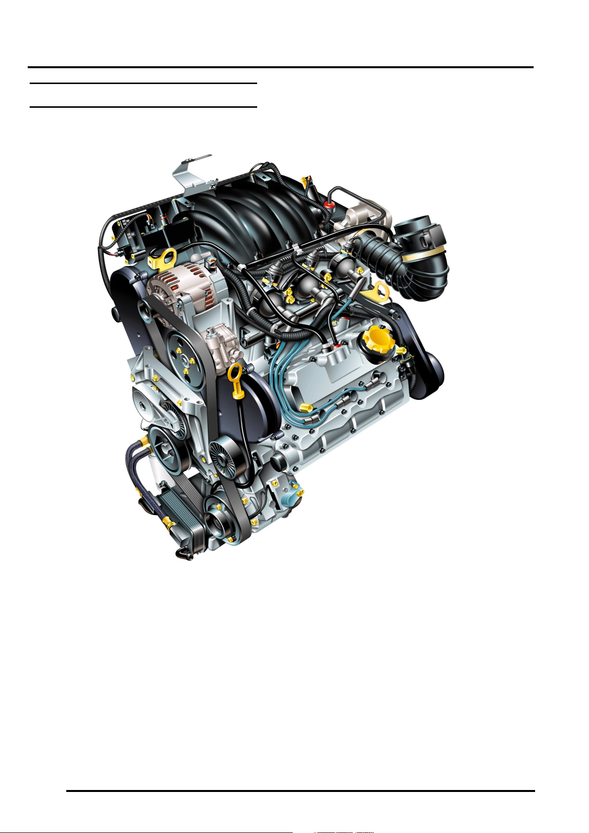
KV6 Engine – General View ........................................................................................................... 12-3-2
KV6 Engine – Internal View ............................................................................................................ 12-3-3
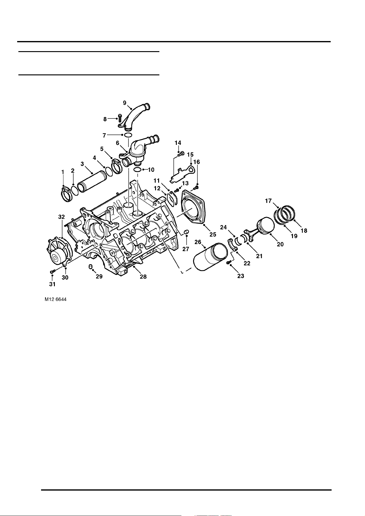
KV6 Engine – Cylinder Block Components..................................................................................... 12-3-4
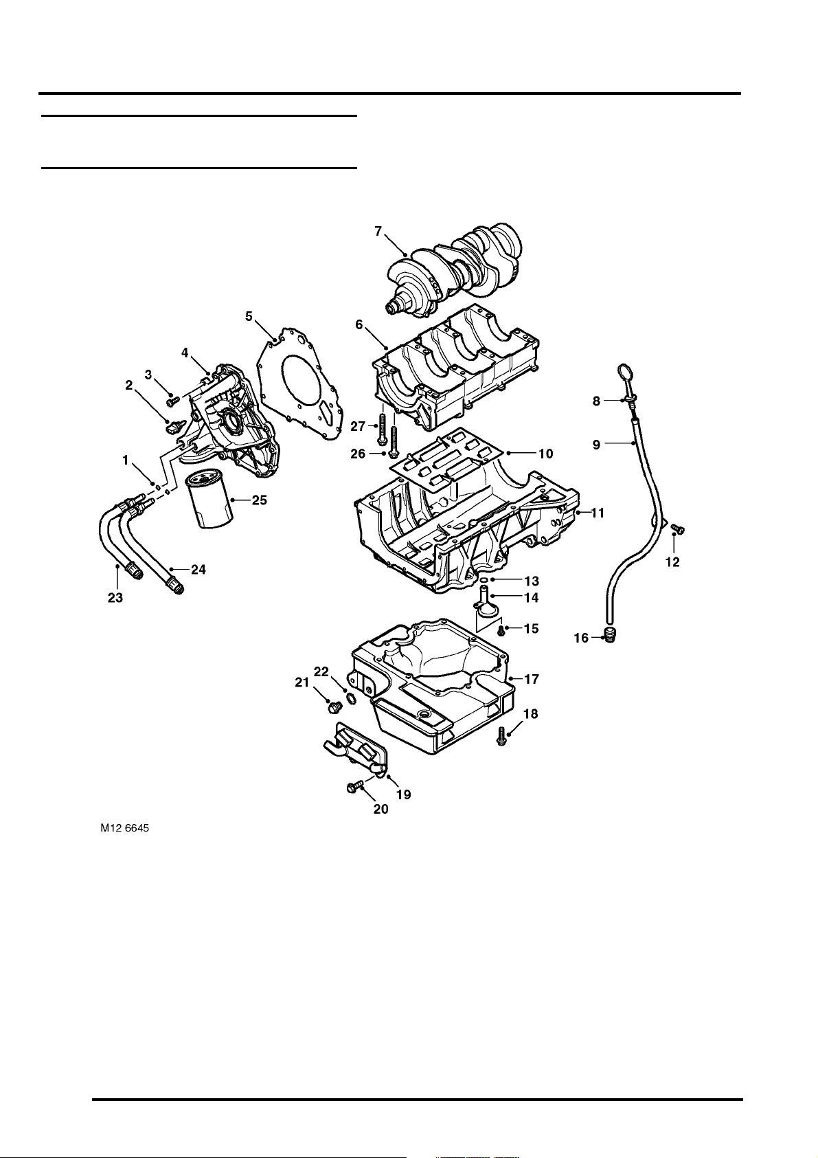
KV6 Engine – Crankshaft, Sump and Oil Pump Assembly............................................................. 12-3-6
KV6 Engine – Cylinder Head Components ..................................................................................... 12-3-8
KV6 Engine – Manifolds and Engine Cover Components .............................................................. 12-3-10
KV6 Engine – Camshaft Drive Belt Components............................................................................ 12-3-12
Description ...................................................................................................................................... 12-3-13
Operation ........................................................................................................................................ 12-3-17
EMISSION CONTROL - K SERIES KV6 .................................................. 17-3-1
Emission Control Component Layout – Crankcase and Exhaust ................................................... 17-3-1
Emission Control Component Layout – EVAP ................................................................................ 17-3-2
Description ...................................................................................................................................... 17-3-4
ENGINE MANAGEMENT SYSTEM - SIEMENS ...................................... 18-4-1
Engine Management System Component Location........................................................................ 18-4-2
Engine Management System Control Diagram – Sheet 1 of 2 ....................................................... 18-4-4
Engine Management System Control Diagram – Sheet 2 of 2 ....................................................... 18-4-6
Description ...................................................................................................................................... 18-4-8
Operation ........................................................................................................................................ 18-4-41
Cruise Control Component Location............................................................................................... 18-4-43
Cruise Control System Control Diagram......................................................................................... 18-4-44
Cruise Control Description .............................................................................................................. 18-4-46
Cruise Control Operation ................................................................................................................ 18-4-49
FUEL DELIVERY SYSTEM - K SERIES KV6 .......................................... 19-3-1
Fuel Delivery System Component Layout ...................................................................................... 19-3-1
Fuel Delivery System Schematic .................................................................................................... 19-3-2
Description ...................................................................................................................................... 19-3-3
Operation ........................................................................................................................................ 19-3-7
COOLING SYSTEM - K SERIES KV6...................................................... 26-3-1
Cooling System Component Layout - Sheet 1 of 2......................................................................... 26-3-2
Cooling System Component Layout - Sheet 2 of 2......................................................................... 26-3-4
Cooling System Coolant Flow ......................................................................................................... 26-3-5
Description ...................................................................................................................................... 26-3-6
Operation ........................................................................................................................................ 26-3-8
CONTENTS 1
Page 5

CONTENTS
MANIFOLD AND EXHAUST SYSTEM - K SERIES KV6 ......................... 30-3-1
Inlet Manifold Component Layout ................................................................................................... 30-3-1
Inlet Manifold Chamber Component Layout ................................................................................... 30-3-2
Exhaust System Component Layout – Sheet 1 of 2 ....................................................................... 30-3-3
Exhaust System Component Layout – Sheet 2 of 2 ....................................................................... 30-3-4
Description...................................................................................................................................... 30-3-5
Operation........................................................................................................................................ 30-3-7
INTERMEDIATE REDUCTION DRIVE ..................................................... 41-1
Intermediate Reduction Drive ......................................................................................................... 41-1
Description...................................................................................................................................... 41-2
Operation........................................................................................................................................ 41-3
AUTOMATIC GEARBOX - JATCO........................................................... 44-1
JATCO Automatic Gearbox Component Location .......................................................................... 44-1
JATCO Automatic Gearbox ............................................................................................................ 44-2
JATCO Automatic Gearbox - Exploded View ................................................................................. 44-3
JATCO Automatic Gearbox - Valve Block and Solenoid Valves .................................................... 44-4
JATCO Automatic Gearbox Control Diagram ................................................................................. 44-6
Description...................................................................................................................................... 44-8
Operation........................................................................................................................................ 44-43
DRIVESHAFTS ......................................................................................... 47-1
Drive Shaft and Propeller Shaft Component Layout....................................................................... 47-1
Front Drive Shaft Components ....................................................................................................... 47-2
Rear Drive Shaft Components........................................................................................................ 47-3
Propeller Shaft and VCU Components ........................................................................................... 47-4
Description...................................................................................................................................... 47-5
REAR AXLE AND FINAL DRIVE.............................................................. 51-1
Rear Differential.............................................................................................................................. 51-2
Description...................................................................................................................................... 51-4
STEERING ................................................................................................ 57-1
Steering Components - KV6........................................................................................................... 57-1
Description...................................................................................................................................... 57-2
Operation........................................................................................................................................ 57-10
FRONT SUSPENSION.............................................................................. 60-1
Front Suspension Component Location ......................................................................................... 60-1
Front Suspension Component Detail.............................................................................................. 60-2
Description...................................................................................................................................... 60-4
2CONTENTS
Page 6

CONTENTS
REAR SUSPENSION................................................................................ 64-1
Rear Suspension Component Location .......................................................................................... 64-1
Rear Suspension Component Detail............................................................................................... 64-2
Description ...................................................................................................................................... 64-4
BRAKES ................................................................................................... 70-1
Brake System Layout (KV6)............................................................................................................ 70-1
Description ...................................................................................................................................... 70-2
Operation ........................................................................................................................................ 70-14
Handbrake Component Layout ....................................................................................................... 70-21
Description ...................................................................................................................................... 70-22
RESTRAINT SYSTEMS............................................................................ 75-1
SRS Component Layout ................................................................................................................. 75-1
SRS Control Diagram ..................................................................................................................... 75-2
Description ...................................................................................................................................... 75-4
Operation ........................................................................................................................................ 75-11
Front Seat Belt Components........................................................................................................... 75-13
Rear Seat Belt Components - Three Door Models ......................................................................... 75-14
Rear Seat Belt Components - Five Door Models ............................................................................ 75-15
Description ...................................................................................................................................... 75-16
HEATING AND VENTILATION................................................................. 80-1
Heating and Ventilation System Component Layout ...................................................................... 80-1
Heater Assembly Components ....................................................................................................... 80-2
Description ...................................................................................................................................... 80-3
Operation ........................................................................................................................................ 80-11
AIR CONDITIONING................................................................................. 82-1
A/C Refrigerant System Component Layout – KV6 Series Engines............................................... 82-1
A/C System Schematic Layout ....................................................................................................... 82-2
A/C Control Component Layout ...................................................................................................... 82-3
A/C System Control Schematic....................................................................................................... 82-4
Description ...................................................................................................................................... 82-6
Operation ........................................................................................................................................ 82-20
WIPERS AND WASHERS ........................................................................ 84-1
Windscreen Wiper Components ..................................................................................................... 84-1
Rear Screen Wiper Components .................................................................................................... 84-2
Washer Components ...................................................................................................................... 84-3
Description ...................................................................................................................................... 84-4
Operation ........................................................................................................................................ 84-7
CONTENTS 3
Page 7

CONTENTS
CONTROL UNITS ..................................................................................... 86-3-1
Control Unit Locations .................................................................................................................... 86-3-1
Description...................................................................................................................................... 86-3-2
COMMUNICATION DATA BUSES ........................................................... 86-4-1
CAN Bus Control Diagram.............................................................................................................. 86-4-1
Diagnostic Buses (Up To 2002 Model Year) .................................................................................. 86-4-2
Diagnostic Buses (From 2002 Model Year).................................................................................... 86-4-4
Description...................................................................................................................................... 86-4-6
SECURITY................................................................................................. 86-5-1
Locking and Alarm System Component Layout.............................................................................. 86-5-1
Locking and Alarm System Control Diagram.................................................................................. 86-5-2
Description...................................................................................................................................... 86-5-4
Immobilisation System Component Layout .................................................................................... 86-5-11
Immobilisation System Control Diagram......................................................................................... 86-5-12
Description...................................................................................................................................... 86-5-13
Operation........................................................................................................................................ 86-5-16
WINDOWS................................................................................................. 86-6-1
Window Component Layout............................................................................................................ 86-6-1
Side Door Window Control Diagram............................................................................................... 86-6-3
Tail Door Window Control Diagram ................................................................................................ 86-6-5
Description...................................................................................................................................... 86-6-6
Operation........................................................................................................................................ 86-6-9
DRIVING AIDS .......................................................................................... 86-10-1
Park Distance Control..................................................................................................................... 86-10-1
Park Distance Control Control Diagram.......................................................................................... 86-10-2
Description...................................................................................................................................... 86-10-3
PDC System Operation .................................................................................................................. 86-10-7
NAVIGATION SYSTEM ............................................................................ 87-1
Navigation System Component Location........................................................................................ 87-1
Description...................................................................................................................................... 87-2
INSTRUMENTS......................................................................................... 88-1
Instrument Pack Component Location - Front View ....................................................................... 88-1
Instrument Pack Component Location - Front View (2004MY Only) .............................................. 88-2
Instrument Pack Component Layout - Rear View........................................................................... 88-3
Instrument Pack Components - Exploded View ............................................................................. 88-4
Description...................................................................................................................................... 88-5
4CONTENTS
Page 8

ENGINE - K SERIES KV6DESCRIPTION AND OPERATION
ENGINE - K SERIES KV6
This page is intentionally left blank
Deze pagina werd opzettelijk niet gebruikt
Cette page est intentionnellement vierge
Diese Seite ist leer
Questa pagina è stata lasciata in bianco di proposito
Esta página foi deixada intencionalmente em branco
Esta página fue dejada en blanco intencionalmente
DESCRIPTION AND OPERATION 12-3-1
Page 9
ENGINE - K SERIES KV6
KV6 Engine – General View
M12 7452
12-3-2 DESCRIPTION AND OPERATION
Page 10
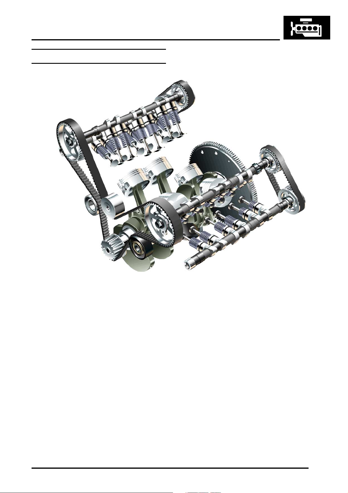
KV6 Engine – Internal View
ENGINE - K SERIES KV6
M12 6813
DESCRIPTION AND OPERATION 12-3-3
Page 11
ENGINE - K SERIES KV6
KV6 Engine – Cylinder Block Components
12-3-4 DESCRIPTION AND OPERATION
Page 12

1 Clip – coolant pump to thermostat pipe
2 'O' ring – coolant pump to thermostat pipe
3 Pipe – coolant pump to thermostat
4 'O' ring – coolant pump to thermostat pipe
5 Clip – coolant pump to thermostat pipe
6 Thermostat housing
7 'O' ring – coolant outlet elbow to cylinder block
8 Bolt – coolant outlet elbow to cylinder block
9 Coolant outlet elbow
10 'O' ring – thermostat housing to cylinder block
11 Blanking plate – coolant outlet
12 Seal – blanking plate
13 Screw – blanking plate (2 off)
14 Bolt – engine lifting bracket, rear (2 off)
15 Engine lifting bracket – rear
16 Screw – crankshaft rear oil seal (5 off)
17 2nd compression ring
18 Top compression ring
19 Oil control ring
20 Piston
21 Big-end upper bearing shell
22 Big-end bearing cap
23 Bolt – big-end bearing cap to connecting rod
(2 off per piston)
24 Big-end lower bearing shell
25 Crankshaft rear oil seal
26 Cylinder liner (6 off)
27 Dowel – cylinder block to cylinder head (4 off)
28 Cylinder block
29 Dowel – cylinder block to lower crankcase
(4 off)
30 Engine coolant pump
31 Screw – coolant pump to cylinder block (7 off)
32 Seal – coolant pump to cylinder block
ENGINE - K SERIES KV6
DESCRIPTION AND OPERATION 12-3-5
Page 13
ENGINE - K SERIES KV6
KV6 Engine – Crankshaft, Sump and Oil Pump Assembly
12-3-6 DESCRIPTION AND OPERATION
Page 14

1 'O' rings – oil filter housing to oil cooler pipes
2 Oil pressure switch
3 Screw – oil pump to cylinder block (16 off)
4 Oil pump and oil filter housing assembly
5 Gasket – oil pump housing
6 Bearing ladder
7 Crankshaft
8 Dipstick
9 Dipstick tube
10 Baffle plate – lower crankcase extension
11 Lower crankcase extension
12 Screw – dipstick tube to cylinder block
13 'O' ring – oil pick-up pipe
14 Oil pick-up pipe with integral strainer
15 Screw – oil pick-up pipe to lower crankcase
16 Connector (quick fit) – dipstick tube to sump
17 Sump
18 Bolt – sump to lower crankcase
(10 off; 5 x short, 5 x long)
19 Oil cooler
20 Bolt – oil cooler to sump (3 off)
21 Oil drain plug
22 Seal – oil drain plug
23 Pipe – oil cooler to oil filter housing
24 Pipe – oil filter housing to oil cooler
25 Oil filter cartridge
26 Bolt (long) – bearing ladder to cylinder block
(8 off)
27 Bolt (short) – bearing ladder to cylinder block
(8 off)
ENGINE - K SERIES KV6
DESCRIPTION AND OPERATION 12-3-7
Page 15
ENGINE - K SERIES KV6
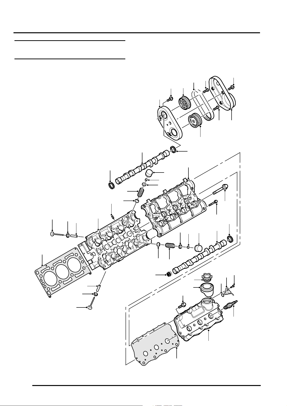
KV6 Engine – Cylinder Head Components
12
13
14
15
11
1
16
17
18
5
4
3
2
8
9
10
19
6
7
20
42
43
44
39
45
40
41
46
29
27
28
26
30
25
32
31
24
37
21
23
33
34
22
35
36
M12 6646
LH cylinder bank shown, RH cylinder bank similar
12-3-8 DESCRIPTION AND OPERATION
38
Page 16

1 Rear drive belt inner cover
2 Bolt – camshaft rear drive belt inner cover
(4 off)
3 Camshaft gear – rear inlet
4 Drive belt – rear camshaft
5 Bolt – inlet camshaft gear
6 Bolt – camshaft rear drive belt outer cover
(3 off)
7 Rear drive belt outer cover
8 Bolt – exhaust camshaft gear
9 Camshaft gear – rear exhaust
10 Seal – inlet camshaft, rear oil
11 Inlet camshaft
12 Seal – inlet camshaft, front oil
13 Stud – cylinder head to intake manifold (2 off)
14 Valve stem oil seal – inlet (6 off)
15 Valve spring – inlet (6 off)
16 Valve spring cap – inlet (6 off)
17 Collet – inlet valve (12 off)
18 Tappet – inlet valve (6 off)
19 Camshaft carrier
20 Bolt – cylinder head (8 off)
21 Bolt – camshaft carrier to cylinder head (22 off)
22 Seal – exhaust camshaft, rear oil
23 Exhaust camshaft
24 Tappet – exhaust valve (6 off)
25 Collet – exhaust valve (12 off)
26 Valve spring cap – exhaust (6 off)
27 Valve stem oil seal – exhaust (6 off)
28 Valve spring – exhaust (6 off)
29 Seal – exhaust camshaft, front oil
30 Bolt – camshaft cover (14 off)
31 Seal – oil filler cap
32 Oil filler cap
33 'O' ring – CMP sensor
34 CMP sensor
35 Bolt – CMP sensor
36 Spark plug (3 off)
37 Camshaft cover
38 Gasket – camshaft cover
39 Inlet valve (6 off)
40 Valve seat insert – inlet (6 off)
41 Valve guide – inlet (6 off)
42 Gasket – cylinder head
43 Exhaust valves (6 off)
44 Valve seat insert – exhaust (6 off)
45 Valve guides – exhaust (6 off)
46 Cylinder head
ENGINE - K SERIES KV6
DESCRIPTION AND OPERATION 12-3-9
Page 17

ENGINE - K SERIES KV6
KV6 Engine – Manifolds and Engine Cover Components
12-3-10 DESCRIPTION AND OPERATION
Page 18

1 Strap – engine acoustic cover
2 Bolt – engine acoustic cover strap to manifold
chamber
3 Engine acoustic cover
4 Bolt – manifold chamber to RH inlet manifold
(4 off)
5 Manifold chamber
6 Bolt – throttle body assembly to manifold
chamber (4 off)
7 Throttle body assembly
8 Inlet manifold, RH
9 Seal - manifold chamber to LH inlet manifold
(3 off)
10 Guide block – HT lead
11 Stud – HT lead guide block/acoustic cover
fixing
12 Inlet manifold, LH
13 Bolt – inlet manifold to cylinder head LH (7 off)
14 Gasket - inlet manifold to cylinder head (LH)
15 Fuel rail
16 Bolt – inlet manifold to cylinder head
17 Gasket – inlet manifold to cylinder head, RH
18 'O' ring - inlet manifold to top cover RH (3 off)
ENGINE - K SERIES KV6
DESCRIPTION AND OPERATION 12-3-11
Page 19
ENGINE - K SERIES KV6
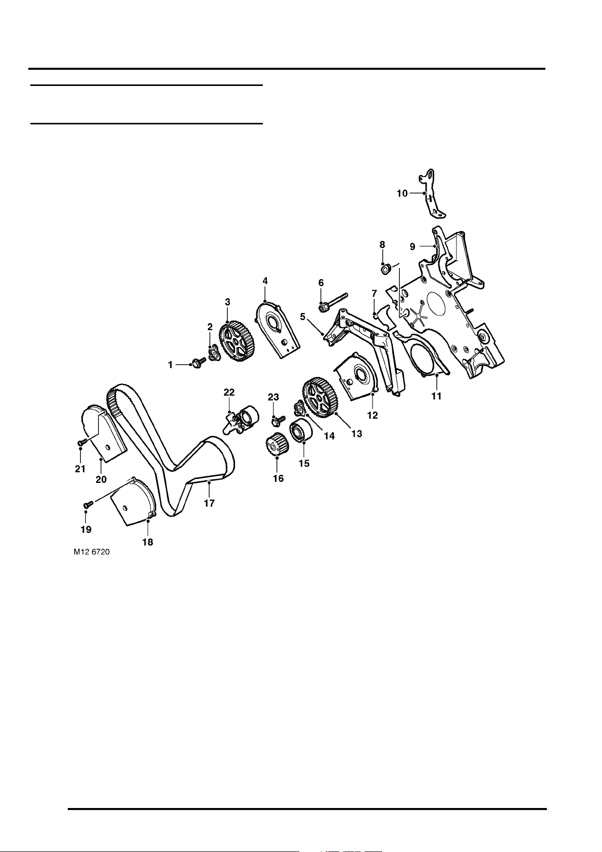
KV6 Engine – Camshaft Drive Belt Components
1 Bolt – timing gear to inlet camshaft (RH)
2 Hub – camshaft front timing gear (RH)
3 Camshaft front timing gear (RH)
4 Drive belt (front) backplate cover – RH
5 Engine mounting bracket
6 Bolt – engine mounting bracket to front plate
(4 off)
7 Cover plate – drive belt
8 Blanking plug
9 Engine front plate
10 Engine lifting bracket – front
11 Cover – lower drive belt
12 Drive belt (front) backplate cover – LH
13 Camshaft front timing gear (LH)
12-3-12 DESCRIPTION AND OPERATION
14 Hub – camshaft front timing gear (LH)
15 Idler pulley – drive belt
16 Crankshaft timing gear
17 Drive belt – front
18 Front drive belt outer cover (LH)
19 Screw – front drive belt outer cover to inner
cover, LH (3 off)
20 Front drive belt outer cover (RH)
21 Screw – front drive belt outer cover to inner
cover, RH (3 off)
22 Tensioner assembly – front drive belt
23 Bolt – timing gear to inlet camshaft (LH)
Page 20

ENGINE - K SERIES KV6
Description
General
The KV6 is of all aluminium construction, with a 90° V configuration. The KV6 uses long cylinder head bolts engaging
in threads 70 mm below the mating face of the cylinder block to attach the cylinder head to the cylinder block. This
ensures sufficient structural stiffness to take advantage of the compressive strength of aluminium alloy and minimise
tensile loadings. There are 8 cylinder head bolts for each cylinder head, located below the camshafts.
The engine features 24 valves, sequential fuel injection, liquid cooling and is transverse mounted. It is controlled by
a Siemens engine management system utilising a range of sensors to constantly monitor and optimise engine
performance.
+ ENGINE MANAGEMENT SYSTEM - SIEMENS, DESCRIPTION AND OPERATION, Description.
Cylinder Block Components
The cylinder block components are described below:
Cylinder Block and Main Bearing Ladder
The cylinder block is constructed of an aluminium alloy and is cast in three sections:
l Cylinder block.
l Main bearing ladder.
l Lower crankcase extension.
For strength and rigidity, the main bearing ladder is manufactured from special alloy A357TF as used in manufacturing
components in the aerospace industry. The main bearing ladder is secured to the cylinder block with 16 bolts, thus
creating a very rigid crankcase 'box'. A separate outer crankcase extension adds further strength to the lower end of
the cylinder block. The lower crankcase extension is sealed to the underside of the cylinder block, using jointing
compound, and secured with 10 bolts. Fitted to the lower crankcase is an aluminium alloy sump.
Pistons and Cylinder Liners
The aluminium alloy, thermal expansion, lightweight pistons, with semi-floating gudgeon pins, are offset to the thrust
side and are carried on forged steel connecting rods. Pistons and cylinder liners are supplied in two grades, 'A' and
'B' and are also colour coded to assist identification. The pistons are marked to ensure they are correctly oriented in
the cylinder liner; the 'FRONT' mark should be toward the front of the engine.
The cylinder block is fitted with 'damp' cylinder liners, the bottom stepped half of the cylinder liner being a sliding fit
into the lower part of the cylinder block. The liners are sealed in the block with a bead of sealant applied around the
stepped portion of the cylinder liner. The top of the cylinder liner is sealed by a multi-layer steel cylinder head gasket
when the cylinder head is fitted.
The cylinder liner diameters are smaller than the big-end forging of the connecting rods and need to be removed
complete with pistons and connecting rods from the cylinder block.
Connecting Rods
The KV6 engine utilises forged steel H-sectioned connecting rods, with the gudgeon pin being an interference fit in
the small end of the connecting rod. The big-ends are horizontally split.
Big-end bearing diametric clearance is controlled by selective bearing shells with three grades of thickness. The bigend upper and lower bearing shells are plain with locating tags.
DESCRIPTION AND OPERATION 12-3-13
Page 21

ENGINE - K SERIES KV6
Piston Rings
Each piston is fitted with two compression rings and an oil control ring. The top compression rings are chrome-plated
steel. The 2nd compression rings are chrome-plated cast iron. The oil control rings have stainless steel top and
bottom rails and integral expander rings.
Crankshaft, Sump and Oil Pump Components
The crankshaft and sump components are described below:
Crankshaft
The short, stiff crankshaft is supported on four main bearings, with each pair of crankpins mutually offset by 30° to
give equal firing intervals. Cast in Spheroidal Graphite (SG) iron, the crankshaft has cold rolled fillets on all journals,
except the outer mains, for toughness and failure resistance. End-float is controlled by thrust washer halves at the top
and bottom of the rear main bearing.
Main Bearings
Oil grooves are provided in the upper halves of all the main bearing shells to supply oil, via drillings in the crankshaft,
to the connecting rod big-end bearings. The lower halves of the bearing shells in the bearing ladder are plain.
Sump
The cast aluminium sump is a wet-type, sealed to the lower crankcase extension using sealant applied to the sump
flange. The sump is fixed to the lower crankcase extension using 10 bolts. A baffle plate is fitted in the lower crankcase
extension to minimise the effects of oil slosh.
An oil pick-up with integral strainer is located in the centre of the sump oil well, as a source for the supply of engine
lubrication oil to the oil pump. Oil is sucked up though the end of the pick–up and strained to prevent solid matter from
entering the oil pump.
Oil Pump
The oil pump is directly driven from the crankshaft. The oil pump housing includes the oil pressure relief valve, oil filter,
oil pressure switch and return/supply outlets for the engine oil cooler.
Oil Filter
A full-flow, disposable canister-type oil filter is attached to the oil pump housing at the front of the engine.
Oil Cooler
A liquid cooled oil cooler keeps the engine lubrication oil cool, under heavy loads and high ambient temperatures.
The oil cooler is cooled by the engine cooling system and attached to a bracket secured to the front of the sump by
three bolts. Oil is delivered to and from the oil cooler through hoses connected to the oil pump housing. Hoses from
the engine cooling system are connected to two pipes on the oil cooler for the supply and return of coolant.
Oil Pressure Switch
The oil pressure switch is located in a port at the outlet side of the oil filter. It detects when a safe operating pressure
has been reached during engine starting and initiates the illumination of a warning light in the instrument pack if the
oil pressure drops below a given value.
12-3-14 DESCRIPTION AND OPERATION
Page 22

ENGINE - K SERIES KV6
Cylinder Head Components
The cylinder head components are described below:
Cylinder Head
The cross-flow cylinder heads are based on a four valve, central spark plug combustion chamber, with the inlet ports
designed to induce swirl and control the speed of the induction charge. This serves to improve combustion and hence
fuel economy, performance and exhaust emissions.
LH and RH cylinder heads are identical castings.
Camshafts
Twin camshafts on each cylinder bank are retained by a camshaft carrier, line bored with the cylinder head. The
camshafts are located by a flange which also controls end-float. A crossover drive for the exhaust camshaft, from the
rear of the inlet camshaft is by a short toothed belt, which allows for a much shorter and simpler run for the main
camshaft drive belt at the front of the engine.
The exhaust camshaft drive gears have dampers integral with the gear to minimise torsional vibration. The inlet
camshaft for the LH cylinder head incorporates a reluctor which is used in conjunction with the Camshaft Position
(CMP) sensor to measure engine position. The CMP sensor is bolted to the LH camshaft cover.
+ ENGINE MANAGEMENT SYSTEM - SIEMENS, DESCRIPTION AND OPERATION, Description.
Cylinder Head Gasket
The KV6 utilises a multi-layer stainless steel cylinder head gasket. The gasket comprises four stainless steel
functional layers, and a stainless steel distance layer to maintain fitted thickness. A full embossment profile is
employed to seal the combustion gases and half embossments are used to provide a durable fluid seal. Sealing
characteristics are further enhanced by the application of a fluro-elastomer surface coating to all layers of the gasket.
Hydraulic Tappets
Self-adjusting, lightweight, hydraulic tappets are fitted on top of each valve and are operated directly by the camshaft.
The valve stem oil seals are moulded onto a metal base which also acts as the valve spring seat on the cylinder head.
Valves
The exhaust valves are of the carbon break type. A machined profile on the valve stem removes any build up of carbon
in the combustion chamber end of the valve guide. All valve seats are machined in three planes, improving valve to
seat sealing.
Camshaft Cover and Engine Cover Components
The camshaft cover and engine cover components are described below:
Acoustic Cover
A moulded plastic acoustic cover is fitted over the engine to absorb engine generated noise. Foam is bonded on the
inside surface of the acoustic cover and a rubber seal is fitted around the oil filler cap.
The acoustic cover is located on the engine by two rubber studs on the underside of the acoustic cover. A rubber
strap, at the rear of the engine, and two quick release fasteners, at the front of the acoustic cover, secure the acoustic
cover in position.
Resonators and part of the engine intake duct are integrated into the acoustic cover, and the engine air filter is
installed in a compartment below a lid secured with two Torx bolts.
A metal foil heatshield is installed on the underside of the acoustic cover.
A rubber duct connects the engine intake duct in the acoustic cover to the RH inner wing. A further duct is installed
between the inner and outer wings to draw engine air from the base of the A post.
DESCRIPTION AND OPERATION 12-3-15
Page 23

ENGINE - K SERIES KV6
Throttle Body Assembly
The throttle body is an electrically actuated unit controlled by the Engine Control Module (ECM). The position of the
throttle plate is controlled by a DC motor and a return spring integrated into the throttle body. Two feedback
potentiometers supply throttle plate position signals to the ECM for closed loop control.
Four Torx bolts secure the throttle body to the inlet manifold chamber. A rubber seal, keyed into a groove in the inlet
manifold chamber, ensures the joint is air tight.
Inlet Manifold Chamber
The inlet manifold chamber is a sealed plastic assembly. The inlet manifold chamber combines plenum resonance for
good low speed torque, with variable length primary tracts for optimum mid and high speed torque.
The throttle body assembly feeds into a 'Y' piece which separates into two secondary inlet pipes. The secondary pipes
feed into two main plenums, one for each bank of three cylinders. At the closed end of the plenums is a balance valve,
controlled by an electric actuator, that connects the two plenums together.
The variable intake system uses valves and actuators to vary the overall tract length of the inlet manifold chamber.
The aluminium alloy inlet manifolds are sealed to each cylinder head with gaskets and to the inlet manifold chamber
with 'O' rings and seals.
+ MANIFOLD AND EXHAUST SYSTEM - K SERIES KV6, DESCRIPTION AND OPERATION, Description.
12-3-16 DESCRIPTION AND OPERATION
Page 24

ENGINE - K SERIES KV6
Operation
Lubrication Circuit
The lubrication system is of the full-flow filtration, force fed type.
Oil is drawn, via a strainer and pick-up pipe in the sump, through the bearing ladder and into a crankshaft driven oil
pump which has an integral pressure relief valve. The strainer in the pick-up pipe prevents any ingress of foreign
particles from passing through to the inlet side of the oil pump and damaging the oil pump and restricting oil drillings.
The oil pressure relief valve in the oil pump opens if the oil pressure becomes excessive and diverts oil back around
the pump.
Pressurised oil is pumped through a full-flow cartridge type oil filter, mounted on the oil pump housing. The lubrication
system is designed so that a higher proportion of oil flow is directed to the cylinder block main oil gallery while a lower
proportion of oil flow, (controlled by a restrictor in the oil filter housing), is directed to the engine oil cooler. The
remainder of the oil flow from the outlet side of the oil filter is combined with the return flow from the oil cooler before
being passed into the cylinder block main oil gallery.
The main oil gallery has drillings that direct the oil to the main bearings. Cross drillings in the crankshaft main bearings
carry the oil to the connecting rod big-end bearings.
The oil pressure switch is located at the outlet side of the oil filter housing to sense the oil pressure level before the
oil flow enters the main gallery in the engine block. A warning lamp in the instrument pack is illuminated if low oil
pressure is detected.
Oil at reduced pressure is directed to each cylinder bank via two restrictors in the cylinder block/cylinder head locating
dowels, one at the front on the LH bank and the other at the rear on the RH bank. Oil then passes through a drilling
in the cylinder head to the camshaft carrier, where it is directed via separate galleries to the camshaft bearings and
hydraulic tappet housings. Return oil from the cylinder head drains into the sump via the cylinder head bolt passages.
Crankcase Ventilation
A positive crankcase ventilation system is used to vent blow-by gas from the crankcase to the air intake system. The
blow-by gas passes through a gauze oil separator in the camshaft cover, and then through hoses into the throttle
housing and inlet manifold.
+ EMISSION CONTROL - K SERIES KV6, DESCRIPTION AND OPERATION, Description.
DESCRIPTION AND OPERATION 12-3-17
Page 25
ENGINE - K SERIES KV6
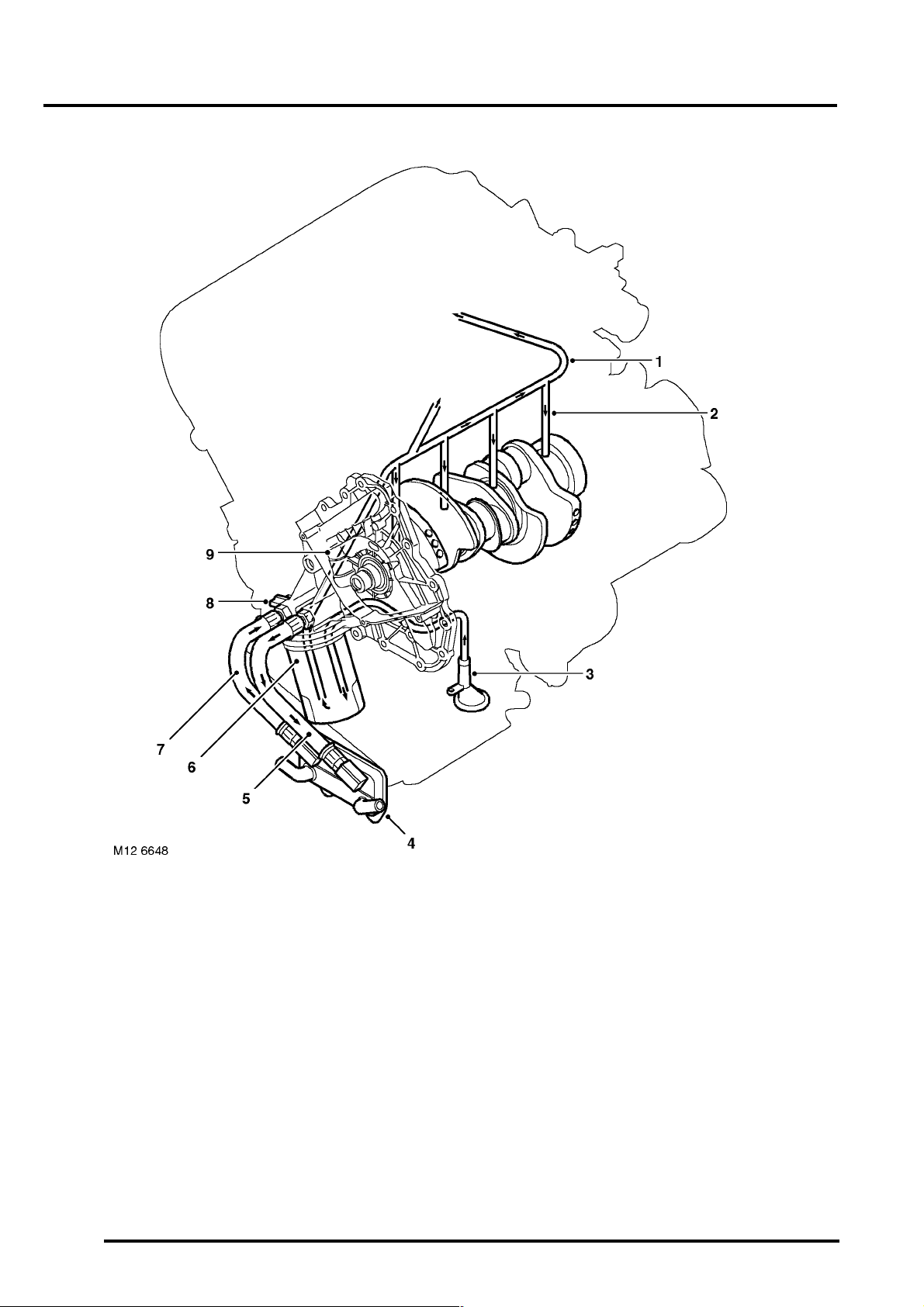
Crankshaft Oil Supply
1 Cylinder block main oil gallery
2 Cross drillings to crankshaft main bearings
3 Oil pick-up pipe with integral strainer
4 Oil cooler
5 Oil cooler supply pipe
12-3-18 DESCRIPTION AND OPERATION
6 Oil filter cartridge
7 Oil cooler return pipe
8 Oil pressure switch
9 Oil pump with integral oil pressure relief valve
Page 26
ENGINE - K SERIES KV6
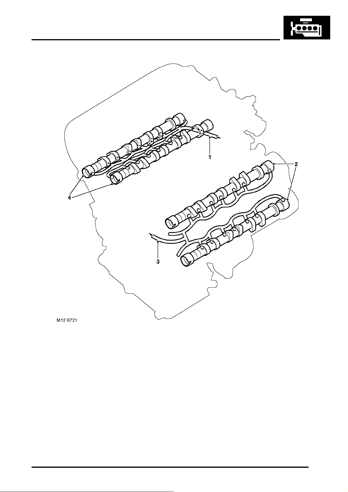
Cylinder Head Component Oil Supply
1 From RH cylinder block main gallery
2 LH cylinder head camshafts
3 From LH cylinder block main gallery
4 RH cylinder head camshafts
DESCRIPTION AND OPERATION 12-3-19
Page 27

ENGINE - K SERIES KV6
12-3-20 DESCRIPTION AND OPERATION
Page 28

EMISSION CONTROL - K SERIES KV6
EMISSION CONTROL - K SERIES KV6DESCRIPTION AND OPERATION
Emission Control Component Layout – Crankcase and Exhaust
1 Crankcase breather hose to intake duct
2 Crankcase breather hose to inlet manifold
3 Catalytic converters
DESCRIPTION AND OPERATION 17-3-1
Page 29
EMISSION CONTROL - K SERIES KV6
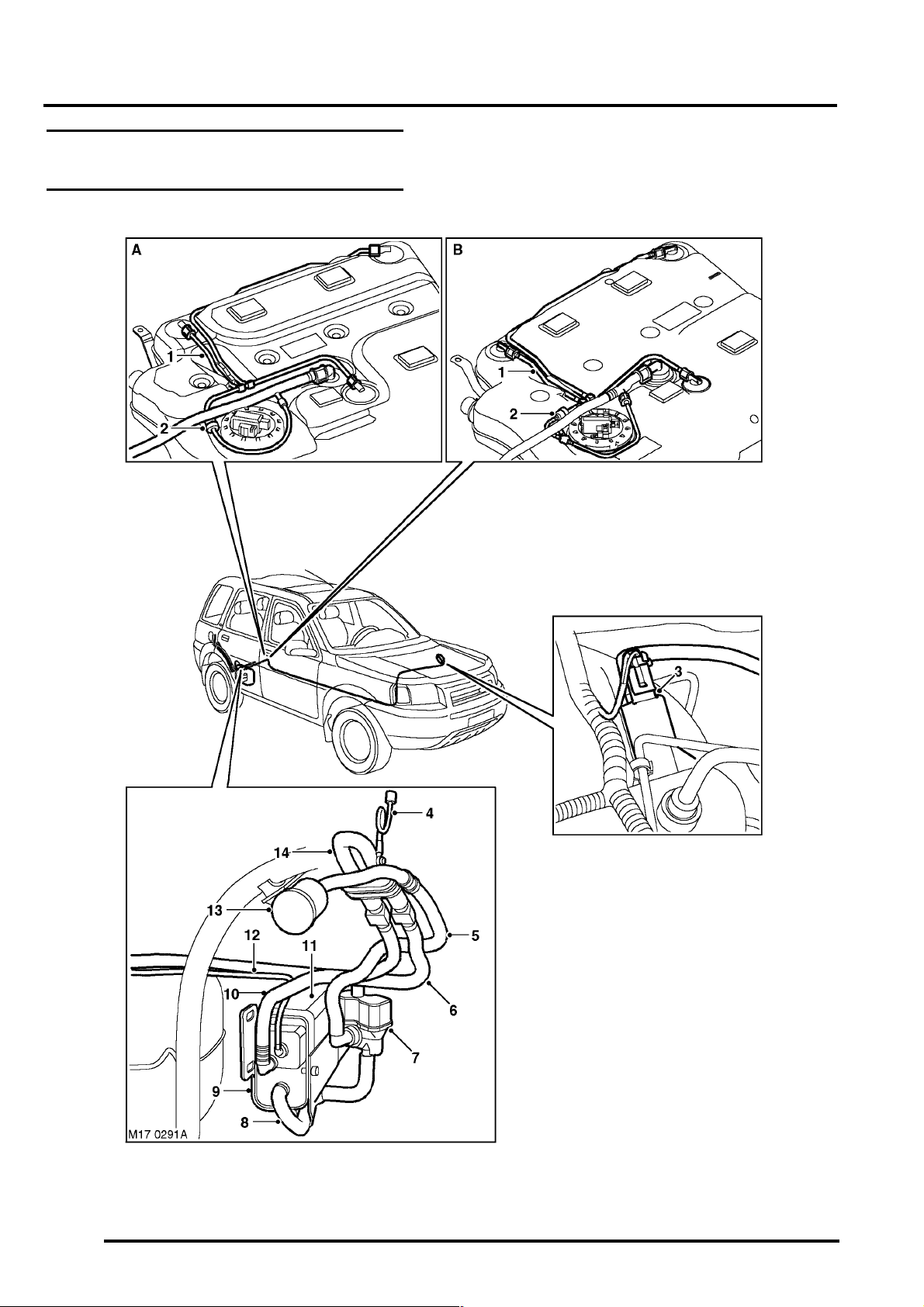
Emission Control Component Layout – EVAP
A = Vehicles up to 2002.5 Model Year
B = Vehicles from 2002.5 Model Year
17-3-2 DESCRIPTION AND OPERATION
Page 30

EMISSION CONTROL - K SERIES KV6
1 Fuel tank vent pipes
2 Two-way valve
3 Purge valve
4 Recirculation pipe
5 DMTL to air filter vent pipe
6 Fuel tank to vapour separator vent pipe
7 DMTL
8 Canister to DMTL vent pipe
9 Canister support bracket
10 Vapour separator to canister vent pipe
11 EVAP canister
12 Canister to purge valve vent pipe
13 Air filter
14 Vapour separator
DESCRIPTION AND OPERATION 17-3-3
Page 31

EMISSION CONTROL - K SERIES KV6
Description
General
The vehicle is fitted with the following control systems to reduce emissions released into the atmosphere:
l Crankcase emission control.
l Exhaust emission control.
l Evaporative emissions (EVAP) control.
CAUTION: In many countries it is against the law for a vehicle owner or an unauthorised dealer to modify or
tamper with emission control equipment. In some cases, the vehicle owner and/or the dealer may even be
liable for prosecution.
The emission control systems fitted to the vehicle are designed to keep the emissions within the legal limits, at the
time of manufacture, provided that the engine and the fuel system components are correctly maintained and in good
mechanical condition.
Crankcase Emission Control System
The crankcase is vented via the oil drain passages in the cylinder blocks and cylinder heads and two ports in each
camshaft cover. Plastic pipes connect the larger ports in the camshaft covers to the intake duct, on the upstream side
of the throttle disc. The smaller ports in the camshaft covers are connected to the inlet manifold, downstream of the
throttle body, also by plastic pipes. Each of the smaller ports incorporate a restrictor and a gauze oil separator to
prevent oil being drawn out of the camshaft covers with the blow-by gases. Quick release locking collars and 'O' rings
are used for all of the pipe connections with the camshaft covers, throttle body and air intake duct.
When the engine is running with the throttle disc closed, the depression downstream of the throttle disc draws
crankcase gases into the inlet manifold through the smaller ports in the camshaft covers. Clean air, from the upstream
side of the throttle disc, is drawn into the crankcase through the larger ports in the camshaft covers to limit the
depression produced in the crankcase.
When the engine is running with the throttle disc wide open, the upstream and downstream sides of the throttle disc,
and thus the two ports in each camshaft cover, are subjected to similar, relatively weak, depression levels. Crankcase
gases are then drawn out of both ports in each camshaft cover, with the majority being drawn out of the unrestricted
larger ports and into the throttle body.
At interim throttle disc positions the flow of the crankcase gases varies, between those produced at the closed and
wide open throttle disc positions, depending on the depression levels produced upstream and downstream of the
throttle disc.
Exhaust Emission Control
The engine management systems provide accurately metered quantities of fuel to the combustion chambers to
ensure the most efficient use of fuel and to minimise the exhaust emissions. In some markets, to reduce the carbon
monoxide and hydrocarbons content of the exhaust gases, catalytic converters are installed in the exhaust system.
A catalytic converter is integrated into each downpipe close to the exhaust manifolds.
17-3-4 DESCRIPTION AND OPERATION
Page 32

EMISSION CONTROL - K SERIES KV6
In the catalytic converters the exhaust gases are passed through honeycombed ceramic elements coated with a
special surface treatment called 'washcoat'. The washcoat increases the surface area of the ceramic elements by a
factor of approximately 7000. On top of the washcoat is a coating containing the elements which are the active
constituents for converting harmful emissions into inert by-products. The active constituents consist of platinum and
rhodium. Platinum adds oxygen to the carbon monoxide and the hydrocarbons in the exhaust gases, to convert them
into carbon dioxide and water respectively. The rhodium removes oxygen from the Nitrous Oxides (NOx) to convert
them into nitrogen.
The correct operation of the catalytic converters is dependent upon close control of the oxygen content of the exhaust
gas. The quantity of oxygen in the exhaust gas is monitored by the Engine Control Module (ECM) using an input from
the Heated Oxygen Sensor (HO2S) upstream of the catalytic converters. The ECM also monitors the condition of the
catalytic converters using an input from the HO2S downstream of the catalytic converters.
EVAP Control
The EVAP control system reduces the level of hydrocarbons released into the atmosphere by fuel vapour venting from
the fuel tank. A positive pressure leak detection function is incorporated to monitor the integrity of the system. The
EVAP control system comprises:
l A two way valve.
l A vapour separator.
l An EVAP canister.
l A purge valve.
l A Diagnostic Module for Tank Leakage (DMTL).
l An air filter.
l Interconnecting vent pipes.
The EVAP control system is connected to the Onboard Refuelling Vapour Recovery (ORVR) valve and/or the roll over
valves in the fuel tank. The ORVR valve and the roll over valves are float valves that allow inward and outward venting
of the fuel tank, but prevent the escape of fuel into the vent pipes due to fuel slosh or if the vehicle overturns. The
ORVR valve is normally closed when the fuel tank is full and normally open at all other fuel levels. The roll over valves
are normally open at all fuel levels.
When the fuel tank is less than full, venting is unrestricted through the ORVR valve. Only when the fuel tank is full
does venting occur, with changes of tank pressure, through the roll over valves and the two-way valve.
Vapour vented from the fuel tank passes through the EVAP control system to atmosphere. The EVAP canister
absorbs fuel from the vapour and relatively fuel free air vents to atmosphere. Since there is a limit to the storage
capacity of the EVAP canister, when the engine is running fuel is purged from the EVAP canister and burned in the
engine.
To reduce the load on the EVAP canister during refuelling, a proportion of the air expelled from the tank is recirculated
through a pipe connected between the top of the vapour separator and the filler tube. The recirculation flow is induced
by fuel in the filler tube flowing past a restrictor installed in the recirculation pipe connection on the filler tube. With the
recirculation flow present, less fresh air enters the tank, which reduces the volume of vapour generated and fuel
deposited in the EVAP canister.
The DMTL periodically checks the EVAP control system and fuel tank for leaks when the ignition is switched off.
On vehicles from 2002.5 model year – Modifications are introduced to increase the capacity of the fuel tank. The
modification comprises a change to the vent line from the forward Roll Over Valve (ROV). The vent from the ROV now
connects to the vent line between the two-way valve and the vapour separator. Venting from the forward ROV is no
longer restricted by the two-way valve. The ROV now controls the refuelling nozzle shut-off. When the ROV closes,
pressure in the tank increases, shutting off the refuelling nozzle. This modification allows up to 5 litres additional fuel
to be added to the fuel tank.
The fuel tank on vehicles from 2002.5 model year also incorporates a new fabric sleeve over the filler pipe inlet in the
fuel tank. The sleeve reduces the amount of vapour produced during refuelling and the subsequent load on the EVAP
canister.
DESCRIPTION AND OPERATION 17-3-5
Page 33

EMISSION CONTROL - K SERIES KV6
EVAP System Schematic – Vehicles up to 2002.5 Model Year
3
M17 0292
14
15
1
1
17
16
18
131313
12
11
2
10
9
4
6
5
M
8
7
1 Vapour separator
2 EVAP canister
3 DMTL
4 Change-over valve
5 0.5 mm (0.020 in) reference orifice
6 Air pump and motor
7 Air filter
8 ECM
9 Throttle body
10 Purge valve
11 Flap valve
12 Fuel tank
13 Roll over valve
14 ORVR valve
15 Two-way valve
16 Restrictor
17 Fuel filler cap
18 Filler tube
17-3-6 DESCRIPTION AND OPERATION
Page 34

EMISSION CONTROL - K SERIES KV6
EVAP System Schematic – Vehicles from 2002.5 Model Year
3
M17 0362
14
15
1
1
19
2
4
7
6
5
M
17
16
18
10
131313
12
11
9
8
1 Vapour separator
2 EVAP canister
3 DMTL
4 Change-over valve
5 0.5 mm (0.020 in) reference orifice
6 Air pump and motor
7 Air filter
8 ECM
9 Throttle body
11 Flap valve
12 Fuel tank
13 Roll over valve
14 ORVR valve
15 Two-way valve
16 Restrictor
17 Fuel filler cap
18 Filler tube
19 Fabric sleeve
10 Purge valve
Two-way Valve
The two-way valve limits the pressure and depression in the fuel tank and, during refuelling, induces automatic cutoff in the refuelling nozzle when the fuel in the tank reaches the full level. The two-way valve is installed in the vent
pipe from the tank, next to the fuel pump assembly.
The two-way valve is a normally closed valve that opens, to release pressure from the fuel tank, at 18 to 50 mbar (0.26
and 0.73 lbf/in
2
). Air is allowed to flow back into the fuel tank, as the pressure in the tank decreases, through a non
return valve within the body of the two-way valve. The nominal opening pressure of the non return valve is 1 mbar
(0.015 lbf/in
2
).
During refuelling, if the fuel in the tank reaches the full level outward venting becomes restricted, which creates a back
pressure in the filler tube and automatically closes the refuelling nozzle. The restriction is caused by the fuel closing
the ORVR valve.
DESCRIPTION AND OPERATION 17-3-7
Page 35

EMISSION CONTROL - K SERIES KV6
Vapour Separator
The vapour separator is installed at the front of the RH rear wheel arch, behind the wheel arch liner. The vapour
separator prevents the charcoal in the EVAP canister being saturated with fuel, by separating any liquid from the
vapour vented from the fuel tank. Separated fuel from the vapour separator drains back to the fuel tank through the
vent pipe.
EVAP Canister
The EVAP canister is installed at the front of the RH rear wheel arch, behind the wheel arch liner. Charcoal in the
EVAP canister absorbs and stores fuel from the vapour vented from the fuel tank. When the engine is running, fuel is
purged from the EVAP canister when the purge valve opens and clean air is drawn through the charcoal.
EVAP Canister
1 Canister housing
2 Purge valve connection
Purge Valve
The purge valve is installed on the inlet manifold chamber, next to the throttle body, and connected to the EVAP
canister by a vent pipe installed on the underside of the vehicle, next to the fuel delivery pipe.
The purge valve is controlled by the Engine Control Module (ECM) and remains closed below a preset coolant
temperature and engine speed, to protect engine tune and catalytic converter performance. When engine operating
conditions are suitable, the ECM opens the purge valve and the depression in the inlet manifold draws fuel vapour
from the EVAP canister.
DMTL
The DMTL is connected to the atmospheric vent of the charcoal canister and incorporates an electric air pump, a
normally open change-over valve and a 0.5 mm (0.020 in) reference orifice. The DMTL operates only after the ignition
is switched off and is controlled by the ECM, which also monitors the air pump and the change-over valve for faults.
Air Filter
The air filter prevents dust being drawn into the EVAP system. A breather tube connects the DMTL to the air filter,
which is located above the RH rear wheelarch liner, immediately below the fuel filler cap.
3 Vapour separator connection
4 DMTL connection
17-3-8 DESCRIPTION AND OPERATION
Page 36

EMISSION CONTROL - K SERIES KV6
Leak Diagnostic Operation
To check the fuel tank and EVAP system for leaks, the ECM operates the air pump in the DMTL and monitors the
current draw. Initially, the ECM establishes a reference current by pumping air through the reference orifice and back
to atmosphere. Having established a reference current, the ECM then closes the change-over valve, which seals the
EVAP system (the purge valve already being closed), and diverts the output from the air pump around the reference
orifice and into the EVAP system.
When the change-over valve is first closed, the load on the pump drops to zero, then, provided there are no leaks, the
pump begins to pressurise the EVAP system and the load and current draw of the pump begin to increase. By
monitoring the rate and level of current increase, the ECM can determine if there is a leak in the system.
During the leak check, the ECM energises a heating element in the air pump to prevent condensation forming and
producing an incorrect current reading.
Leaks are classified as minor (equivalent to hole diameter of 0.5 to 1.0 mm (0.02 to 0.04 in) or major (equivalent to
hole diameter of 1.0 mm (0.04 in) or greater).
The ECM conducts a check for major leaks each time the ignition is switched off, provided the following baseline
conditions are met:
l The ECM is in power down mode more than 3 seconds after the ignition is switched off.
l The vehicle speed is zero.
l The engine speed is zero.
l The pressure altitude (derived from engine load calculations) is below 1830 m (6000 ft).
l The engine coolant temperature is more than 2.25 °C (36 °F).
l The ambient temperature is between 0 and 40 °C (32 and 104 °F).
l The EVAP canister load factor is 3 or less (the load factor is a measure, between –1 and +30, of the amount of
fuel vapour stored in the EVAP canister, where –1 is 0% fuel vapour, 0 is stoichiometric fuel vapour level and
+30 is 100% saturated with fuel vapour).
l The fuel tank level is valid and between 15 and 85 % of the nominal capacity.
l The engine running time during the previous ignition on cycle was more than 20 minutes.
l Battery voltage is between 10.94 and 14.52 volts.
l The last engine off time was more than 150 minutes.
l No errors with the following functions or components:
l Road speed.
l EVAP system load monitoring.
l Engine coolant temperature.
l Ambient air temperature.
l Fuel level.
l Purge valve.
l DMTL.
DESCRIPTION AND OPERATION 17-3-9
Page 37

EMISSION CONTROL - K SERIES KV6
A check for minor leaks is only conducted after every 14th major leak check or after refuelling is detected.
At the end of the leak check the ECM stops the air pump and opens the change-over valve.
If the fuel filler cap is opened or refuelling is detected during the leak check, by a sudden drop in the current draw or
rise in fuel level, the leak check is aborted.
If a leak is detected during the check, the ECM stores an appropriate fault code in memory. If a leak is detected on
two consecutive checks, the ECM illuminates the MIL on the next drive cycle.
The duration of the leak check is between 40 and 270 seconds, depending on results and the level of fuel in the tank.
A leak test can be invoked using TestBook/T4, which overrides the baseline conditions requirement.
Leak Check Sequence
A = Pump motor current; B = Time
X = Current draw for tight system; Y = Current draw for minor leak; Z = Current draw for major leak
1 Pump motor energised: Air directed through reference orifice to atmosphere, to establish reference current.
2 Reference current.
3 Change-over valve energised: Air directed through EVAP canister into fuel tank.
4 Major leak check completed: If current is above stored value, no major leak present; if current is below stored
value, major leak present.
5 Minor leak check completed, with no minor leak detected, when current exceeds reference value.
6 Minor leak check completed, with minor leak detected, when current stabilises at or below reference current.
17-3-10 DESCRIPTION AND OPERATION
Page 38

ENGINE MANAGEMENT SYSTEM - SIEMENSDESCRIPTION AND OPERATION
ENGINE MANAGEMENT SYSTEM - SIEMENS
This page is intentionally left blank
Deze pagina werd opzettelijk niet gebruikt
Cette page est intentionnellement vierge
Diese Seite ist leer
Questa pagina è stata lasciata in bianco di proposito
Esta página foi deixada intencionalmente em branco
Esta página fue dejada en blanco intencionalmente
DESCRIPTION AND OPERATION 18-4-1
Page 39

ENGINE MANAGEMENT SYSTEM - SIEMENS
Engine Management System Component Location
18-4-2 DESCRIPTION AND OPERATION
Page 40

ENGINE MANAGEMENT SYSTEM - SIEMENS
1 APP sensor (Up to 2003 model year shown)
2 A/C compressor clutch relay
3 Main relay
4 ECM relay
5 Fuel pump relay
6 ECM
7 Electric throttle
8 IAT sensor
9 MAF sensor
10 CMP sensor
11 Thermostat monitoring sensor
12 CKP sensor
13 ECT sensor
14 LH bank ignition coil (x 3) (Up to 2003 model
year shown)
15 Fuel injector (x 6)
16 Knock sensors
17 RH bank ignition coil (x 3) (Up to 2003 model
year shown)
18 MIL
19 Engine malfunction lamp
20 Front HO2S (x 2)
21 Rear HO2S (x 2)
DESCRIPTION AND OPERATION 18-4-3
Page 41

ENGINE MANAGEMENT SYSTEM - SIEMENS
Engine Management System Control Diagram – Sheet 1 of 2
18-4-4 DESCRIPTION AND OPERATION
A = Hardwired connection
Page 42

ENGINE MANAGEMENT SYSTEM - SIEMENS
1 Ignition switch
2 Fuse 35, passenger compartment fusebox
3 ECM relay
4 Fuel injector (x 6)
5 Main relay
6 Fuse 4, engine compartment fusebox
7 A/C compressor relay
8 Cooling fan ECU
9 ECT sensor
10 Cruise control interface ECU
11 Fuse 3, engine compartment fusebox
12 LH front HO2S
13 RH front HO2S
14 LH rear HO2S
15 RH rear HO2S
16 CMP sensor
17 MAF sensor
18 Electric throttle
19 Knock sensors
20 APP sensor (Up to 2003 model year shown)
21 IAT sensor
22 Fuse 5, engine compartment fusebox
23 Thermostat monitoring sensor
24 Brake pedal sensor
25 Fuse 6, passenger compartment fusebox
26 Alternator
27 ECM
DESCRIPTION AND OPERATION 18-4-5
Page 43

ENGINE MANAGEMENT SYSTEM - SIEMENS
Engine Management System Control Diagram – Sheet 2 of 2
16
X
3
1
2
4
Y
18
4
3
2
x1000 RPM km/h
1
0
TC
5
6
7
8
120
100
140
80
160
60
180
40
200
2020
220
0
5
17
19
7
6
15
14
13
A
M19 3378
A = Hardwired connection; D = CAN bus; J = Diagnostic ISO 9141 K line
18-4-6 DESCRIPTION AND OPERATION
12
8
11
D
10
J
9
Page 44

ENGINE MANAGEMENT SYSTEM - SIEMENS
1 Fuse 10, engine compartment fusebox
2 Inertia fuel cut-off switch
3 Fuel pump relay
4 Fuel tank unit
5 Fuse 2, engine compartment fusebox
6 Ignition coil (x 6) (Up to 2003 model year
shown)
7 Fuse 1, engine compartment fusebox
8 DMTL
9 VIS balance valve motor
10 VIS power valves motor
11 EVAP canister purge valve
12 CKP sensor
13 Vacuum enhancer solenoid valve – Up to 2003
model year
14 Diagnostic socket
15 EAT ECU
16 ABS modulator
17 Immobilisation ECU
18 Instrument pack
19 ECM
DESCRIPTION AND OPERATION 18-4-7
Page 45

ENGINE MANAGEMENT SYSTEM - SIEMENS
Description
General
The KV6 engine is fitted with a Siemens MS43 Engine Management System (EMS), which is an adaptive system that
maintains engine performance at the optimum level throughout the life of the engine.
The EMS consists of an Engine Control Module (ECM) that uses inputs from engine sensors and from other vehicle
systems to continuously monitor driver demand and the current status of the engine. From the inputs the ECM
calculates the Air Fuel Ratio (AFR) and ignition timing required to match engine operation with driver demand, then
outputs the necessary control signals to the electric throttle, fuel injectors and ignition coils. The ECM also outputs
control signals to operate the:
l Air Conditioning (A/C) compressor.
+ AIR CONDITIONING, DESCRIPTION AND OPERATION, Description.
l Engine cooling fans.
+ COOLING SYSTEM - K SERIES KV6, DESCRIPTION AND OPERATION, Description.
l Evaporative emissions (EVAP) purge valve and Diagnostic Module for Tank Leakage (DMTL).
+ EMISSION CONTROL - K SERIES KV6, DESCRIPTION AND OPERATION, Description.
l Fuel pump.
+ FUEL DELIVERY SYSTEM - K SERIES KV6, DESCRIPTION AND OPERATION, Description.
l Variable Intake System (VIS).
+ MANIFOLD AND EXHAUST SYSTEM - K SERIES KV6, DESCRIPTION AND OPERATION,
Description.
The ECM also interfaces with the:
l Immobilisation ECU, for re-mobilisation of the engine fuel supply.
+ SECURITY, DESCRIPTION AND OPERATION, Description.
l Cruise control interface ECU, to operate cruise control.
+ ENGINE MANAGEMENT SYSTEM - SIEMENS, DESCRIPTION AND OPERATION, Cruise Control
Description.
l Electronic Automatic Transmission (EAT) ECU, to assist with control of the gearbox.
+ AUTOMATIC GEARBOX - JATCO, DESCRIPTION AND OPERATION, Description.
Sensor inputs and engine performance are monitored by the ECM, which illuminates the SERVICE ENGINE SOON
(MIL) and/or the SERVICE ENGINE warning lamps in the instrument pack if a fault is detected.
As part of the security system's immobilisation function, a vehicle specific security code is programmed into the ECM
and the immobilisation ECU during production. The ECM cannot function unless it is connected to an immobilisation
ECU with the same code. In service, replacement ECM's are supplied uncoded and must be configured, using
TestBook/T4, to learn the vehicle security code from the immobilisation ECU.
A 'flash' Electronic Erasable Programmable Read Only Memory (EEPROM) allows the ECM to be externally
configured, using TestBook/T4, with market specific or new tune information up to 14 times. The current engine tune
data can be accessed and read using TestBook/T4.
The ECM memorises the position of the crankshaft and the camshaft when the engine stops. During cranking on the
subsequent start the ECM confirms their positions from sensor inputs before initiating fuel injection and ignition.
To achieve optimum performance the ECM is able to 'learn' the individual characteristics of an engine and adjust the
fuelling calculations to suit. This capability is known as adaptive fuelling. Adaptive fuelling also allows the ECM to
compensate for wear in engine components and to compensate for the tolerance variations of the engine sensors.
If the ECM suffers an internal failure, such as a breakdown of the processor or driver circuits, there is no back up
system or limp home capability. If a sensor circuit fails to supply an input, where possible the ECM adopts a substitute
or default value, which enables the engine to function, although with reduced performance in some cases.
18-4-8 DESCRIPTION AND OPERATION
Page 46

ECM
ENGINE MANAGEMENT SYSTEM - SIEMENS
The ECM is located in the engine compartment, in the E-box. Five connectors provide the interface between the ECM
and the vehicle wiring.
The E-box is a lidded container that provides a protected environment for the ECM and the EAT ECU. An open hub,
centrifugal fan powered by an electric motor ventilates the E-box with air from the passenger compartment. Exhaust
air from the E-box is directed back into the passenger compartment. The ventilating and exhaust air is routed between
the passenger compartment and the E-box through plastic ducting and corrugated rubber hoses. Operation of the
cooling fan is controlled by a thermostatic switch in the E-box. The thermostatic switch receives a power feed while
the ignition switch is in position II. If the temperature in the E-box reaches 35 °C (95 °F) the thermostatic switch closes
and connects the power feed to the fan, which runs to cool the E-box with air from the passenger compartment. When
the temperature in the E-box decreases to 27 °C (81 °F), the thermostatic switch opens and stops the fan. To prevent
the fan seizing up in colder climates, where it may not operate for long periods of time, the fan also receives a power
feed direct from the starter circuit so that it runs each time the engine is cranked.
ECM Harness Connectors
DESCRIPTION AND OPERATION 18-4-9
Page 47

ENGINE MANAGEMENT SYSTEM - SIEMENS
Connector C0331 Pin Details
Pin No. Description Input/Output
1 to 3 Not used –
4 Engine cooling fan control Output
5 and 6 Not used –
7 APP sensor earth 2 –
8 APP sensor signal 2 Input
9 APP sensor supply 2 Output
10 Fuel pump relay coil Output
11 Not used –
12 APP sensor earth 1 –
13 APP sensor signal 1 Input
14 APP sensor supply 1 Output
15 to 19 Not used –
20 DMTL pump motor Output
21 Alternator load sensing Input
22 Vehicle speed Input
23 VIS balance valve position feedback Input
24 Brake pedal sensor, Brake Lamp Switch (BLS) signal Input
25 Not used –
26 Ignition sense Input
27 Cruise control MFL signal Input
28 Brake pedal sensor, Brake Test Switch (BTS) signal Input
29 A/C compressor clutch relay coil Output
30 DMTL change-over valve Output
31 Not used –
32 Diagnostic ISO 9141 K line Input/Output
33 Immobilisation ECU Input
34 VIS power (butterfly) valves position feedback Input
35 Not used –
36 CAN bus high Input/Output
37 CAN bus low Input/Output
38 Thermostat monitoring sensor earth –
39 Thermostat monitoring sensor signal Input
40 Not used –
Connector C0332 Pin Details
Pin No. Description Input/Output
1 Ignition coil 5 Output
2 Ignition coil 3 Output
3 Ignition coil 1 Output
4 Not used –
5 Ignition earth –
6 Not used –
7 Ignition coil 4 Output
8 Ignition coil 6 Output
9 Ignition coil 2 Output
18-4-10 DESCRIPTION AND OPERATION
Page 48

ENGINE MANAGEMENT SYSTEM - SIEMENS
Connector C0603 Pin Details
Pin No. Description Input/Output
1 Ignition sense Input
2 and 3 Not used –
4 Electronic earth –
5 Fuel injector earth –
6 Power stage earth –
7 Battery power supply Input
8 Ignition power supply Input
9 Ignition power supply Input
Connector C0604 Pin Details
Pin No. Description Input/Output
1 LH bank front HO2S heater drive Output
2 to 6 Not used –
7 LH bank rear HO2S heater drive Output
8 to 12 Not used –
13 RH bank front HO2S heater drive Output
14 LH bank front HO2S signal Input
15 RH bank front HO2S signal Input
16 LH bank rear HO2S signal Input
17 Not used –
18 RH bank rear HO2S signal Input
19 RH bank rear HO2S heater drive Output
20 LH bank front HO2S earth –
21 RH bank front HO2S earth –
22 LH bank rear HO2S earth –
23 Main relay coil Output
24 RH bank rear HO2S earth –
Connector C0606 Pin Details
Pin No. Description Input/Output
1 MAF sensor signal Input
2 Not used –
3 Vacuum enhancer solenoid valve – Up to 2003 model year Output
4 Not used –
5 CMP sensor signal Input
6 Not used –
7 Throttle feedback potentiometer supply Output
8 CKP sensor signal Input
9 Not used –
10 Throttle feedback potentiometer 2 signal Input
11 VIS balance valve motor drive Output
12 to 16 Not used –
17 MAF sensor earth –
18 CMP sensor earth –
19 Throttle feedback potentiometer 1 signal Input
20 Throttle feedback potentiometer earth –
21 CKP sensor earth –
DESCRIPTION AND OPERATION 18-4-11
Page 49

ENGINE MANAGEMENT SYSTEM - SIEMENS
Pin No. Description Input/Output
22 IAT sensor signal Input
23 IAT sensor earth –
24 ECT sensor signal Input
25 ECT sensor earth –
26 and 28 Not used –
29 LH bank knock sensor Input
30 LH bank knock sensor Input
31 RH bank knock sensor Input
32 RH bank knock sensor Input
33 Fuel injector 1 Output
34 Fuel injector 3 Output
35 Fuel injector 5 Output
36 Fuel injector 2 Output
37 Fuel injector 6 Output
38 Fuel injector 4 Output
39 to 41 Not used –
42 EVAP purge valve drive Output
43 Throttle motor open drive Output
44 Throttle motor close drive Output
45 to 47 Not used –
48 Knock sensors screen Input
49 VIS power (butterfly) valves motor drive Output
50 Not used –
51 DMTL heater drive Output
52 Not used –
Controller Area Network (CAN) Bus
The ECM is connected to the Anti-lock Braking System (ABS) modulator, EAT ECU and the instrument pack by the
CAN bus.
18-4-12 DESCRIPTION AND OPERATION
Page 50

ENGINE MANAGEMENT SYSTEM - SIEMENS
Electric Throttle
The electric throttle controls the air flow into the engine. In addition to the normal engine power control function, the
electric throttle allows the cruise control, idle speed control and engine speed limiting functions to be performed
without the need for additional hardware.
The electric throttle consists of a throttle body which incorporates a throttle plate driven by a DC motor via reduction
gears. A return spring biases the throttle plate in the closed direction.
Operation of the DC motor is controlled by the ECM, which outputs two Pulse Width Modulated (PWM) signals to an
H bridge drive circuit in the motor. The ECM varies the speed and direction of the motor by varying the duty cycle of
the PWM signals.
To enable closed loop control, the position of the throttle plate is supplied to the ECM by two feedback potentiometers
in the throttle body. The feedback potentiometers have a common 5 volt supply and a common ground connection
from the ECM, and produce separate linear signal voltages to the ECM proportional to the position of the throttle plate.
The ECM uses the signal from feedback potentiometer 1 as the primary signal of throttle plate position, and the signal
from feedback potentiometer 2 for plausibility checks.
l The signal from feedback potentiometer 1 varies between 0.5 volt (0% throttle open) and 4.5 volts (100% throttle
open)
l The signal from feedback potentiometer 2 varies between 4.5 volts (0% throttle open) and 0.5 volt (100% throttle
open)
1 DC motor
2 Electrical connector
While the ignition is on, the ECM continuously monitors the two feedback potentiometers for short and open circuits
and checks the feedback potentiometer signals, against each other and the inputs from the Accelerator Pedal Position
(APP) sensor, for plausibility. If a fault is detected in the feedback potentiometer signals or the DC motor, the ECM:
l Stores a related fault code in memory.
l Illuminates the SERVICE ENGINE warning lamp in the instrument pack.
l Adopts a throttle limp home mode or disables throttle control, depending on the nature of the fault.
The throttle limp home mode adopted depends on the nature of the fault:
l If there is a fault with one feedback potentiometer, or the throttle position controller in the ECM, the ECM limits
vehicle acceleration by limiting throttle plate opening.
l If there is a fault with both feedback potentiometers, the ECM uses fuel injection cut-off to limit engine speed to
1300 rev/min maximum.
3 Reduction gear/ feedback potentiometer
4 Throttle plate
DESCRIPTION AND OPERATION 18-4-13
Page 51

ENGINE MANAGEMENT SYSTEM - SIEMENS
EMS Sensors
The EMS incorporates the following sensors:
l An APP sensor.
l A Crankshaft Position (CKP) sensor.
l A Camshaft Position (CMP) sensor.
l A Mass Air Flow (MAF) sensor.
l An Intake Air Temperature (IAT) sensor.
l An Engine Coolant Temperature (ECT) sensor.
l A thermostat monitoring sensor.
l Four Heated Oxygen Sensors (HO2S).
l Two knock sensors.
APP Sensor – Up to 2003 Model Year
The APP sensor enables the ECM to determine the throttle position requested by the driver on the accelerator pedal.
The APP sensor is installed on the pedal box and consists of a twin track potentiometer with wipers driven by a linkage
connected to the accelerator pedal. Each potentiometer track has a 5 volt supply and ground connection from the
ECM, and produces a linear signal voltage to the ECM proportional to the position of the accelerator pedal. The signal
voltage from track 1 of the potentiometer is approximately double that of the signal voltage from track 2.
From the sensor signals, the ECM determines driver demand as a percentage of pedal travel, where 0% is with the
pedal released and 100% is with the pedal fully depressed. Driver demand is then used to calculate throttle angle,
fuel quantity and ignition timing. The ECM also outputs driver demand on the CAN system, for use by the brake and
gearbox control systems.
18-4-14 DESCRIPTION AND OPERATION
Page 52

ENGINE MANAGEMENT SYSTEM - SIEMENS
The ECM stores the signal values that correspond with closed and wide open throttle, and adapts to new values to
accommodate component wear or replacement.
The signals from the APP sensor are monitored by the ECM for short and open circuits and plausibility. If a fault is
detected, the ECM:
l Stores a related fault code in memory.
l Illuminates the SERVICE ENGINE warning lamp in the instrument pack.
l Inhibits the driver demand message on the CAN bus, which disables the Hill Descent Control (HDC) function of
the ABS modulator and reduces the performance of the automatic gearbox (harsh gear changes and loss of
kickdown).
l Adopts a throttle limp home mode.
The throttle limp home mode adopted depends on the nature of the fault:
l If a fault is detected with one potentiometer track, the ECM limits vehicle acceleration by limiting throttle plate
opening.
l If a fault is detected with both potentiometer tracks, the ECM uses the throttle plate to run the engine at a fixed
speed of 1472 rev/min while the brake pedal is released, and idle speed (750 rev/min) while the brake pedal is
pressed or if there is a brake pedal sensor fault.
l If there is a process fault in the ECM, the ECM either uses fuel injection cut-off to limit engine speed to 1300 rev/
min or disables fuel injection to stop the engine.
DESCRIPTION AND OPERATION 18-4-15
Page 53

ENGINE MANAGEMENT SYSTEM - SIEMENS
Accelerator Pedal Position (APP) Sensor – From 2003 Model Year
The APP sensor is attached to a bracket on the bulkhead. The throttle pedal is an integral part of the sensor. The
pedal is attached to the sensor and rotates an internal pair of sensing elements. The pedal is also connected to two
springs which provide a resistance force to pedal movement to improve feel and control.
The sensor comprises two resistance tracks (potentiometers) and two sliding contacts which are connected directly
to the pedal. The sensor receives a 5V reference voltage from the ECM and outputs a linear voltage relative to the
pedal position. The use of a pair of potentiometers ensures that an output signal is available should one of the tracks
develop a fault.
APP Sensor Output Graph
18-4-16 DESCRIPTION AND OPERATION
A = Voltage
B = Pedal angle (degrees)
C = Full throttle
Page 54

ENGINE MANAGEMENT SYSTEM - SIEMENS
The ECM monitors the output signals from the APP sensor and determines the position, rate of change and direction
of the throttle pedal movement. The ECM stores values which relate to closed throttle and wide open throttle and can
adapt new values to compensate for component wear or replacement.
The ECM uses the closed throttle APP sensor signal to initiate idle speed control and enable an overrun fuel reduction
strategy.
The APP sensor signals are also broadcast on the CAN bus and are used by the EAT ECU to determine the correct
points for gearshifts and kickdown.
The ECM supplies a regulated 5V output to the APP sensor and an earth path for the potentiometer tracks. The earth
path is also used as a screen to protect the integrity of the signals.
If the APP sensor fails to output a signal, the ECM uses a fail-safe mode which increases the idle speed to 1250 rev/
min. The ECM will not respond to movement of the throttle pedal. In the event of a total failure to output a position
signal, the following symptoms will be observed:
l No throttle pedal response
l Failure of emission control
l Automatic transmission kickdown inoperative.
The APP sensor can be tested using the following procedure:
1 Apply a 5V supply to pins 1and 2. Connect pins 4 and 5 to earth.
2 With the sensor in the idle position, check the output voltage at pin 3 – the reading should be approximately
0.73V.
3 With the sensor in the idle position, check the output voltage at pin 6 – the reading should be approximately
0.36V.
DESCRIPTION AND OPERATION 18-4-17
Page 55

ENGINE MANAGEMENT SYSTEM - SIEMENS
CKP Sensor
The CKP sensor provides the ECM with a digital signal of the rotational speed and angular position of the crankshaft,
for use in ignition timing, fuel injection timing and fuel injection quantity calculations. To determine the exact position
of the crankshaft in the engine cycle, the ECM must also use the input from the CMP sensor.
The CKP sensor is mounted on the front of the gearbox housing, in line with the outer circumference of the torque
converter. The sensing tip of the CKP sensor is adjacent to a reluctor ring formed in the periphery of the torque
converter. The reluctor ring has 58 teeth spaced at 6° intervals. A gap equivalent to two missing teeth, 36° After Top
Dead Centre (ATDC) of No. 1 cylinder, provides the ECM with a reference point.
The CKP sensor operates using the Hall effect principle. A permanent magnet inside the sensor applies a magnetic
flux to a semiconductor, which receives a power supply from the main relay. The output voltage from the
semiconductor is fed to the ECM. As the gaps between the poles of the reluctor ring pass the sensor tip the magnetic
flux is interrupted, causing a fluctuation of the output voltage and producing a digital signal.
If the CKP sensor fails the ECM immediately stops the engine.
18-4-18 DESCRIPTION AND OPERATION
Page 56

ENGINE MANAGEMENT SYSTEM - SIEMENS
CMP Sensor
M19 2837A
The CMP sensor provides a signal which enables the ECM to determine the position of the camshaft relative to the
crankshaft. This allows the ECM to synchronise fuel injection for start and run conditions.
The CMP sensor is located on the camshaft cover of the LH (front) cylinder bank, at the opposite end to the camshaft
drive, in line with a 'half moon' reluctor on the exhaust camshaft. The reluctor comprises a single tooth which extends
around 180° of the camshaft circumference.
The CMP sensor operates using the Hall effect principle. A permanent magnet inside the sensor applies a magnetic
flux to a semiconductor, which receives a power supply from the main relay. The output voltage from the
semiconductor is fed to the ECM. As the gap in the reluctor passes the sensor tip, the magnetic flux is interrupted,
causing a fluctuation of the output voltage and producing a digital signal.
If the CMP sensor fails during engine running, the engine will run normally until turned off, but will not restart until the
CMP sensor input is restored.
DESCRIPTION AND OPERATION 18-4-19
Page 57

ENGINE MANAGEMENT SYSTEM - SIEMENS
MAF Sensor
The MAF sensor provides a signal which the ECM uses for engine load calculations.
The MAF sensor is a hot film type, and is located in the intake system between the air filter housing and the throttle
body.
A closed-loop control circuit in the MAF sensor maintains a thick film resistor at a constant 200°C (392°F) above
ambient temperature. The current required to maintain the temperature of the thick film resistor, against the cooling
effect of the air flowing through the sensor, provides a precise, non-linear, measure of the air mass entering the
engine.
The MAF sensor receives a battery voltage power supply and generates an output signal to the ECM, between 0 and
5 volts, which is proportional to the air mass drawn into the engine.
In the event of a MAF sensor signal failure, the following symptoms may be apparent:
l During driving engine speed may dip before recovering.
l Difficult starting.
l Engine stalls after starting.
l Delayed throttle response.
l Reduced engine performance.
18-4-20 DESCRIPTION AND OPERATION
Page 58

IAT Sensor
1 Sensor
2 Housing
ENGINE MANAGEMENT SYSTEM - SIEMENS
The IAT sensor provides a signal that enables the ECM to adjust ignition timing and fuelling quantity according to the
intake air temperature, thus ensuring optimum performance, driveability and emissions.
The IAT sensor is a Negative Temperature Coefficient (NTC) thermistor located in a plastic housing installed in the
intake duct between the MAF sensor and the throttle body. The sensor is a push fit in the housing and sealed by an
'O' ring. A clip is integrated into the sensor to secure it in the housing.
If the input from the IAT sensor fails, the vehicle will continue to run. The ECM will substitute a default value using the
information from the speed/load map to run the engine, but adaptive fuelling will be disabled.
DESCRIPTION AND OPERATION 18-4-21
Page 59

ENGINE MANAGEMENT SYSTEM - SIEMENS
ECT Sensor
The ECT sensor provides the ECM with a signal voltage that varies with coolant temperature, to enable the ECM to
adapt the fuelling quantity and ignition timing with changes of engine temperature.
The ECT sensor is located between the cylinder banks, between cylinders 3 and 6.
The ECT sensor consists of an encapsulated Negative Temperature Coefficient (NTC) thermistor which is in contact
with the engine coolant. As the coolant temperature increases the resistance across the sensor decreases and as the
coolant temperature decreases the sensor resistance increases. To determine the coolant temperature, the ECM
supplies the sensor with a regulated 5 volts power supply and monitors the return signal voltage. The ECM also
outputs the coolant temperature on the CAN system, to operate the coolant temperature gauge.
If the ECT signal is missing, or outside the acceptable range, the ECM assumes a default temperature reflecting a
part warm engine condition. This enables the engine to function, but with reduced driveability when cold and increased
emissions, resulting from an over rich mixture, when the engine reaches normal operating temperature. The ECM will
also switch on the cooling fans to prevent the engine and gearbox from overheating.
The following table shows engine coolant temperature values and the corresponding ECT sensor resistance values.
Engine coolant Temperature °C (°F) Sensor Resistance kΩ
- 40 (- 40) 75.501
- 30 (-22) 39.764
-20 (-4) 21.883
-10 (14) 12.452
0 (32) 7.353
10 (50) 4.482
20 (68) 2.814
30 (86) 1.814
40 (104) 1.199
50 (122) 0.8109
60 (140) 0.5601
70 (158) 0.3945
80 (176) 0.2829
90 (194) 0.2064
100 (212) 0.1529
110 (230) 0.1149
120 (248) 0.08761
130 (266) 0.06762
140 (284) 0.05281
150 (302) 0.04171
18-4-22 DESCRIPTION AND OPERATION
Page 60

ENGINE MANAGEMENT SYSTEM - SIEMENS
Thermostat Monitoring Sensor
The input from the thermostat monitoring sensor is used by the ECM to monitor the operation of the cooling system
thermostat and to control the operation of the engine cooling fans.
The thermostat monitoring sensor is a NTC thermistor installed in a plastic 'T' piece in the radiator bottom hose. The
sensor is a push fit in the T piece and sealed by an 'O' ring. A clip is integrated into the sensor to secure it in the T
piece.
DESCRIPTION AND OPERATION 18-4-23
Page 61

ENGINE MANAGEMENT SYSTEM - SIEMENS
HO2S
1 Rear HO2S 2 Front HO2S
The EMS has four HO2S:
l One upstream of each catalytic converter, identified as LH and RH front HO2S.
l One downstream of each catalytic converter, identified as LH and RH rear HO2S.
The LH and RH front HO2S enable the ECM to determine the AFR of the mixture being burned in each cylinder bank
of the engine. The LH and RH rear HO2S enable the ECM to monitor the performance of the catalytic converters and
the front oxygen sensors, and trim fuel.
Each HO2S consists of a sensing element with a protective ceramic coating on the outer surface. The outer surface
of the sensing element is exposed to the exhaust gas, and the inner surface is exposed to ambient air. The difference
in the oxygen content of the two gases produces an electrical potential difference across the sensing element. With
a rich mixture, the low oxygen content in the exhaust gas results in a higher sensor voltage. With a lean mixture, the
high oxygen content in the exhaust gas results in a lower sensor voltage.
During closed loop control, the voltage of the two front HO2S switches from less than 0.3 volt to more than 0.5 volt.
The voltage switches between limits every two to three seconds. This switching action indicates that the ECM is
varying the AFR within the Lambda window tolerance, to maximise the efficiency of the catalytic converters.
18-4-24 DESCRIPTION AND OPERATION
Page 62

ENGINE MANAGEMENT SYSTEM - SIEMENS
Sectioned View of HO2S
1
V
A
3
B
M19 2959
A = Ambient air; B = Exhaust gases
1 Protective ceramic coating
2 Electrodes
The material of the sensing element only becomes active at a temperature of approximately 300 °C (570 °F). To
shorten the warm up time and minimise the emissions from a cold start and low load conditions, each HO2S contains
a heating element powered by a supply from the main relay. The earth paths for the heating elements are controlled
by the ECM. On start up, the current supplied to the heating elements is increased gradually to prevent sudden
heating from damaging the ceramic coating. After the initial warm up period the ECM modulates the earth of the
heating elements, from a map of engine speed against mass air flow, to maintain the HO2S at the optimum operating
temperature.
The nominal resistance of the heating elements is 6 Ω at 20°C (68°F).
If an HO2S fails, the ECM illuminates the MIL. If a front HO2S fails the ECM also adopts open loop fuelling and
catalytic converter monitoring is disabled. If a rear HO2S fails, catalytic converter and front HO2S monitoring is
disabled.
3 Zirconium oxide
2
DESCRIPTION AND OPERATION 18-4-25
Page 63

ENGINE MANAGEMENT SYSTEM - SIEMENS
Knock Sensors
M19 2840
The knock sensors enable the ECM to operate the engine at the limits of ignition advance, for optimum efficiency,
without combustion knock damaging the engine. The ECM uses two knock sensors, one for each cylinder bank,
located between the cylinder banks on cylinders 3 and 4.
The knock sensors consist of piezo ceramic crystals that oscillate to create a voltage signal. During combustion knock,
the frequency of crystal oscillation increases, which alters the signal output to the ECM. The ECM compares the signal
to known signal profiles in its memory. If the onset of combustion knock is detected the ECM retards the ignition timing
for a number of cycles. When the combustion knock stops, the ignition timing is gradually advanced to the original
setting.
The knock sensor leads are of different lengths to prevent incorrect installation.
18-4-26 DESCRIPTION AND OPERATION
Page 64

ENGINE MANAGEMENT SYSTEM - SIEMENS
Ignition Coils – Up to 2003 Model Year
1 RH bank ignition coil 2 LH bank ignition coil
The ECM uses a separate ignition coil for each spark plug. The ignition coils for the LH bank spark plugs are
positioned on the forward tracts of the inlet manifold and connected to the spark plugs with High Tension (HT) leads.
The ignition coils for the RH bank spark plugs are of the plug top design, secured to the camshaft cover with 2 screws.
Each ignition coil has 3 connections in addition to the spark plug connection; an ignition feed from the main relay, an
earth wire for the secondary winding and a primary winding negative (switch) terminal. The switch terminal of each
ignition coil is connected to a separate pin on the ECM to allow independent switching. The ignition coils are charged
whenever the ECM supplies an earth path to the primary winding negative terminal. The duration of the charge time
is held relatively constant by the ECM for all engine speeds. Consequently, the dwell period increases with engine
speed. This type of system, referred to as Constant Energy, allows the use of low impedance coils with faster charge
times and higher outputs.
The ECM calculates the dwell period using inputs from the following:
l Battery voltage (main relay).
l CKP sensor.
l Ignition coil primary current (internal ECM connection).
The spark is produced when the ECM breaks the primary winding circuit. This causes the magnetic flux around the
primary winding to collapse, inducing HT energy in the secondary coil, which can only pass to earth by bridging the
air gap of the spark plug.
Ignition related faults are monitored indirectly by the misfire detection function.
DESCRIPTION AND OPERATION 18-4-27
Page 65

ENGINE MANAGEMENT SYSTEM - SIEMENS
Ignition Coils – From 2003 Model Year
A new 'pencil' type ignition coil is introduced at 2003 model year. This coil is used on all six cylinders and replaces the
two coils used previously. The ECM uses a separate ignition coil for each spark plug. The ignition coils are of the plug
top 'pencil' design which attach to the top of the spark plug. The coils are secured to the camshaft cover with a screw.
The coil has a ribbed area which seals the coil in the spark plug hole in the cylinder head, preventing the ingress of
moisture and debris around the spark plug. These coils eliminate the requirement for HT leads which in turn improves
the ignition system reliability.
Each coil has a three pin female connector which provide for a battery voltage ignition feed from the main relay, an
earth for the secondary winding and a primary winding negative (switch) terminal. The switch terminal of each coil is
connected to a separate pin on the ECM to allow independent switching.
The ignition coils are charged when the ECM provides an earth path to the primary winding negative terminal. The
duration of the charge time is maintained relatively constant by the ECM for all engine speeds with the dwell period
increasing with engine speed. This type of system, referred to as constant energy, allows the use of low impedance
coils with faster charge times and higher outputs. The dwell period is calculated by the ECM using a closed loop
system to limit the current in the system and minimise output energy at low engine speeds. The ECM calculates the
dwell angle using the following inputs for reference:
l Battery voltage (from main relay)
l CKP sensor
l Ignition coil primary current (from internal connection within the ECM).
The primary coil has a resistance of approximately 0.547Ω. The secondary coil resistance cannot be measured due
to a diode in the secondary winding. The ECM monitors the ignition system using the misfire detection function.
The spark is produced when the ECM breaks the primary coil winding circuit. This causes the magnetic flux around
the primary winding to collapse, inducing HT energy in the secondary coil, which can only pass to earth by bridging
the air gap of the spark plug.
18-4-28 DESCRIPTION AND OPERATION
Page 66

ENGINE MANAGEMENT SYSTEM - SIEMENS
Ignition Timing
The ECM calculates ignition timing using inputs from the following sensors:
l CKP sensor.
l MAF sensor.
l Knock sensors.
l TP sensor (idle only).
l ECT sensor.
At start up and idle the ECM sets ignition timing by referencing the ECT and CKP sensors. Once above idle the ignition
timing is controlled according to maps stored in the ECM memory and modified according to additional sensor inputs
and any adaptive value stored in memory. The maps keep the ignition timing within a narrow band that gives an
acceptable compromise between power output and emission control. The ignition timing advance and retard is
controlled by the ECM in order to avoid combustion knock.
Knock Control
The ECM uses active knock control to prevent combustion knock damaging the engine. If the knock sensor inputs
indicate the onset of combustion knock, the ECM retards the ignition timing for that particular cylinder by 3°. If the
combustion knock indication continues, the ECM further retards the ignition timing, in decrements of 3°, for a
maximum of 15° from where the onset of combustion knock was first sensed. When the combustion knock indication
stops, the ECM restores the original ignition timing in increments of 0.75°.
To reduce the risk of combustion knock at high intake air temperatures, the ECM retards the ignition timing if the intake
air temperature exceeds 55 °C (169 °F). The amount of ignition retard increases with increasing air intake
temperature.
Idle Speed Control
The ECM controls the engine idle speed using a combination of fuelling, ignition timing and the electric throttle.
When the engine idle speed fluctuates the ECM initially varies the ignition timing, which produces rapid changes of
engine speed. If this fails to correct the idle speed, the ECM also adjusts the electric throttle and fuelling.
Misfire Detection
The ECM uses the CKP sensor input to monitor the engine for misfires. As the combustion charge in each cylinder is
ignited the crankshaft accelerates, then subsequently decelerates. By monitoring the acceleration/ deceleration
pulses of the crankshaft the ECM can detect misfires.
Low fuel level:
When the fuel tank is almost empty there is a risk that air may be drawn into the fuel system, due to fuel 'slosh', causing
fuel starvation and misfires. To prevent false misfire faults being logged, the ECM disables misfire detection if it
receives a low fuel level message on the CAN bus. Fuel tank content is monitored by the instrument pack, which
transmits the low fuel level message if the fuel tank content decreases to less than 15% (8.85 litres; 2.34 US galls).
Rough road disable:
When the vehicle is travelling over a rough road surface the engine crankshaft is subjected to torsional vibrations
caused by mechanical feedback from the road surface through the transmission. To prevent misinterpretation of these
torsional vibrations as a misfire, the misfire monitor is disabled when a road surface exceeds a roughness limit
programmed into the ECM. The roughness of the road is calculated by the ABS modulator, from the four ABS sensor
inputs, and transmitted to the ECM on the CAN bus.
DESCRIPTION AND OPERATION 18-4-29
Page 67

ENGINE MANAGEMENT SYSTEM - SIEMENS
Fuel Injectors
Fuel Injector – Up to 2003 Model Year
M19 2845A
Fuel Injector – From 2003 Model Year
Up to 2003 Model Year
A split stream, air assisted fuel injector is installed for each cylinder. The injectors are located in the inlet manifolds
and connected to a common fuel rail assembly.
Each injector contains a pintle type needle valve and a solenoid winding. The needle valve is held closed by a return
spring. An integral nozzle shroud contains a ported disc, adjacent to the nozzles. 'O' rings seal the injector in the fuel
rail and the inlet manifold.
The solenoid winding of each injector receives a 12 volt supply from the ECM relay in the engine compartment
fusebox. To inject fuel, the ECM supplies an earth path to the solenoid winding, which energises and opens the needle
valve. When the needle valve opens, the two nozzles direct a spray of atomised fuel onto the back of each inlet valve.
Air drawn through the shroud and ported disc improves atomisation and directional control of the fuel. The air is
supplied from a dedicated port in the intake duct via a plastic tube and tracts formed in the gasket face of the intake
manifolds.
18-4-30 DESCRIPTION AND OPERATION
Page 68

ENGINE MANAGEMENT SYSTEM - SIEMENS
From 2003 Model Year
New injectors are introduced for 2003 model year. The air assist feature is deleted and a standard design injector
installed. The deletion of the air assist injectors also required modifications to the fuel rail, inlet manifold and clean air
duct.
The injectors are located in the inlet manifold and sealed with O-ring seals. The injectors are attached to the fuel rail
with clips and sealed with O-ring seals. A two pin connector on the injector allows for the attachment of the engine
harness connector.
Each injector contains a pintle type needle valve and a solenoid winding. The needle valve is held closed by a return
spring. The solenoid winding of each injector receives a 12 volt supply from the ECM relay in the engine compartment
fusebox. To inject fuel, the ECM supplies an earth path to the solenoid winding, which energises and opens the needle
valve. When the needle valve opens, the two nozzles direct a spray of atomised fuel onto the back of each inlet valve.
All Models
Each injector delivers fuel once per engine cycle, during the inlet stroke. The ECM calculates the open time (duty
cycle) of the injectors from:
l Engine speed.
l Mass air flow.
l Engine temperature.
l Accelerator pedal position (i.e. driver demand).
The fuel in the fuel rail is maintained at a pressure of 3.5 bar (51 lbf/in
pump unit in the fuel tank. An accumulator is attached to the LH fuel rail, to damp out pressure pulses from the pump
and ensure that the pressure in the fuel rail is constant. A Schraeder valve is installed in the fuel rail, above the
accumulator, to provide a pressure test connection for maintenance.
2
) by a pressure regulator incorporated into the
The nominal resistance of the injector solenoid winding is 13 - 16 Ω at 20°C (68°F).
Evaporative Emissions (EVAP) Purge Valve
The ECM provides a PWM earth path to control the operation of the purge valve. When the ECM is in the open loop
fuelling mode the purge valve is kept closed. When the vehicle is moving and in the closed loop fuelling mode the
ECM opens the purge valve.
When the purge valve is open fuel vapour is drawn from the EVAP canister into the inlet manifold. The ECM detects
the resultant enrichment of the AFR, from the inputs of the front HO2S, and compensates by reducing the duty cycle
of the fuel injectors.
Variable Intake System (VIS) Valves
The ECM operates the two VIS valve motors to open and close the VIS valves in a predetermined sequence based
on engine speed and throttle opening. Each VIS valve motor has a permanent power feed from the main relay,
feedback and signal connections with the ECM, and a permanent earth connection. When the engine starts, the VIS
valve motors are both in the valve open position. To close the VIS valves, the ECM applies a power feed to the signal
line of the applicable VIS valve motor. To open the VIS valves, the ECM disconnects the power feed from the signal
line and the VIS valve motor is closed by the power feed from the main relay.
Warning Lamps
Two warning lamps in the instrument are used to indicate faults with the engine management system. The engine
malfunction lamp consists of an amber SERVICE ENGINE legend and is illuminated to indicate the detection of a non
emissions related fault. The Malfunction Indicator Lamp (MIL) consists of an amber SERVICE ENGINE SOON legend
and is illuminated to indicate the detection of an emissions related fault. The ECM operates the warning lamps, by
communicating with the instrument pack on the CAN bus. If a fault that can cause catalytic converter damage is
detected, the warning lamps flash. For other faults the warning lamps are continuously illuminated.
DESCRIPTION AND OPERATION 18-4-31
Page 69

ENGINE MANAGEMENT SYSTEM - SIEMENS
Diagnostics
The ECM incorporates On Board Diagnostics (OBD) software that complies with market legislation current at the time
of manufacture. During engine operation the ECM performs self test and diagnostic routines to monitor the
performance of the engine and the EMS. If a fault is detected the ECM stores a related Diagnostic Trouble Code (DTC,
also known as a 'P' code) in a non volatile memory and, for most faults, illuminates the engine SERVICE ENGINE
(MIL) and/or the SERVICE ENGINE SOON warning lamps. Codes are retrieved using TestBook/T4, which
communicates with the ECM via an ISO 9141 K line connection from the diagnostic socket.
P Code No. Component/Signal Fault Description Warning Lamp Drive Cycle
SERVICE
ENGINE
(MIL)
0030 Pre CAT LH bank HO2S
heater
0031 Pre CAT LH bank HO2S
heater
0032 Pre CAT LH bank HO2S
heater
0036 Post CAT LH bank HO2S
heater
0037 Post CAT LH bank HO2S
heater
0038 Post CAT LH bank HO2S
heater
0050 Pre CAT RH bank HO2S
heater
0051 Pre CAT RH bank HO2S
heater
0052 Pre CAT RH bank HO2S
heater
0056 Post CAT RH bank HO2S
heater
0057 Post CAT RH bank HO2S
heater
0058 Post CAT RH bank HO2S
heater
0100 MAF sensor signal Open circuit No No —
0101 MAF sensor signal Signal implausible Yes No B
0102 MAF sensor signal Short circuit to earth Yes No A
0103 MAF sensor signal Short circuit to battery Yes No A
0105 ECM internal ambient
pressure sensor
0107 ECM internal ambient
pressure sensor
0108 ECM internal ambient
pressure sensor
0109 ECM internal ambient
pressure sensor
0112 IAT sensor Short circuit to earth Yes No B
0113 IAT sensor Open circuit or short circuit to
0116 ECT sensor Signal implausible Yes No B
0117 ECT sensor Short circuit to earth Yes No B
0118 ECT sensor Open circuit or short circuit to
0122 Throttle potentiometer 1 Open circuit or short circuit to
Open circuit or short circuit to
Open circuit Yes No C
Short circuit to earth Yes No C
Short circuit to battery Yes No C
Open circuit Yes No C
Short circuit to earth Yes No C
Short circuit to battery Yes No C
Open circuit Yes No C
Short circuit to earth Yes No C
Short circuit to battery Yes No C
Open circuit Yes No C
Short circuit to earth Yes No C
Short circuit to battery Yes No C
Circuit malfunction No No —
Short circuit to earth Yes No A
Yes No A
battery
Circuit intermittent No No —
Yes No B
battery
Yes No B
battery
Yes Yes B
earth
SERVICE
ENGINE
SOON
18-4-32 DESCRIPTION AND OPERATION
Page 70

ENGINE MANAGEMENT SYSTEM - SIEMENS
P Code No. Component/Signal Fault Description Warning Lamp Drive Cycle
SERVICE
ENGINE
(MIL)
0123 Throttle potentiometer 1 Short circuit to battery Yes Yes B
0125 ECT sensor Open circuit, short circuit to
ground or signal implausible
0128 Thermostat monitoring
sensor
0130 LH bank front HO2S signal Open circuit Yes No C
0131 LH bank front HO2S signal Short circuit to earth Yes No C
0132 LH bank front HO2S signal Short circuit to battery Yes No C
0133 LH bank front HO2S signal Slow response Yes No C
0134 LH bank front HO2S signal Signal not switching Yes No C
0135 LH bank front HO2S heater
circuit
0136 LH bank rear HO2S signal Open circuit Yes No C
0137 LH bank rear HO2S signal Short circuit to earth Yes No C
0138 LH bank rear HO2S signal Short circuit to battery Yes No C
0139 LH bank rear HO2S signal Slow response Yes No C+
0140 LH bank rear HO2S signal No activity Yes No C+
0141 LH bank rear HO2S heater
circuit
0150 RH bank front HO2S signal Open circuit Yes No C
0151 RH bank front HO2S signal Short circuit to earth Yes No C
0152 RH bank front HO2S signal Short circuit to battery Yes No C
0153 RH bank front HO2S signal Slow response Yes No C
0154 RH bank front HO2S signal Signal not switching Yes No C
0155 RH bank front HO2S heater
circuit
0156 RH bank rear HO2S signal Open circuit Yes No C
0157 RH bank rear HO2S signal Short circuit to earth Yes No C
0158 RH bank rear HO2S signal Short circuit to battery Yes No C
0159 RH bank rear HO2S signal Slow response Yes No C
0160 RH bank rear HO2S signal No activity Yes No C+
0161 RH bank rear HO2S heater
circuit
0171 LH bank lambda control Fuelling too lean Yes No C
0172 LH bank lambda control Fuelling too rich Yes No C
0174 RH bank lambda control Fuelling too lean Yes No C
0175 RH bank lambda control Fuelling too rich Yes No C
0201 Fuel injector 1 Open circuit Yes No A
0202 Fuel injector 2 Open circuit Yes No A
0203 Fuel injector 3 Open circuit Yes No A
0204 Fuel injector 4 Open circuit Yes No A
0205 Fuel injector 5 Open circuit Yes No A
0206 Fuel injector 6 Open circuit Yes No A
0222 Throttle potentiometer 2 Open circuit or short circuit to
0223 Throttle potentiometer 2 Short circuit to battery Yes Yes B
0261 Fuel injector 1 Short circuit to earth Yes No A
0262 Fuel injector 1 Short circuit to battery Yes No A
0264 Fuel injector 2 Short circuit to earth Yes No A
0265 Fuel injector 2 Short circuit to battery Yes No A
0267 Fuel injector 3 Short circuit to earth Yes No A
Low coolant temperature –
thermostat stuck open
Open circuit or short circuit to
battery or earth
Open circuit or short circuit to
battery or earth
Open circuit or short circuit to
battery or earth
Open circuit or short circuit to
battery or earth
earth
No No —
Yes No B
No No —
No No —
No No —
No No —
Yes Yes B
SERVICE
ENGINE
SOON
DESCRIPTION AND OPERATION 18-4-33
Page 71

ENGINE MANAGEMENT SYSTEM - SIEMENS
P Code No. Component/Signal Fault Description Warning Lamp Drive Cycle
SERVICE
ENGINE
(MIL)
0268 Fuel injector 3 Short circuit to battery Yes No A
0270 Fuel injector 4 Short circuit to earth Yes No A
0271 Fuel injector 4 Short circuit to battery Yes No A
0273 Fuel injector 5 Short circuit to earth Yes No A
0274 Fuel injector 5 Short circuit to battery Yes No A
0276 Fuel injector 6 Short circuit to earth Yes No A
0277 Fuel injector 6 Short circuit to battery Yes No A
0301 Cylinder 1 Misfire detected Yes No B
0302 Cylinder 2 Misfire detected Yes No B
0303 Cylinder 3 Misfire detected Yes No B
0304 Cylinder 4 Misfire detected Yes No B
0305 Cylinder 5 Misfire detected Yes No B
0306 Cylinder 6 Misfire detected Yes No B
0313 Misfire detection Misfire detected at low fuel level Yes No B
0327 LH bank knock sensor Open circuit Yes No B
0332 RH bank knock sensor Open circuit Yes No B
0335 CKP sensor Open circuit or No signal No No A
0336 CKP sensor Signal implausible No No A
0337 CKP sensor Short circuit to earth No No —
0338 CKP sensor Short circuit to battery No No —
0339 CKP sensor Open circuit/no signal No No —
0340 CMP sensor Open circuit/no signal Yes No A
0341 CMP sensor Signal implausible Yes No A
0351 Ignition coil 1 No spark No No A
0352 Ignition coil 2 No spark No No A
0353 Ignition coil 3 No spark No No A
0354 Ignition coil 4 No spark No No A
0355 Ignition coil 5 No spark No No A
0356 Ignition coil 6 No spark No No A
0420 LH bank catalytic converter Efficiency below threshold – light
off too long
0430 RH bank catalytic converter Efficiency below threshold – light
off too long
0441 Diagnostics EVAP purge flow test failure Yes No B
0442 EVAP system Minor leak Yes No F
0443 Purge valve Short circuit to battery Yes No A
0444 Purge valve Open circuit Yes No A
0445 Purge valve Short circuit to earth Yes No A
0455 EVAP system Major leak Yes No F
0500 Vehicle speed signal Signal implausible Yes No B
0505 ECM idle speed control System malfunction Yes No A
0600 CAN Bus CAN bus off Yes No A
0606 ECM Processor fault Yes No A
1071 LH bank front HO2S Too lean Yes No C
1072 LH bank front HO2S Too rich Yes No C
1074 RH bank front HO2S Too lean Yes No C
1075 RH bank front HO2S Too rich Yes No C
1101 MAF sensor Signal implausible for throttle
angle
Yes No C
Yes No C
No No —
SERVICE
ENGINE
SOON
18-4-34 DESCRIPTION AND OPERATION
Page 72

ENGINE MANAGEMENT SYSTEM - SIEMENS
P Code No. Component/Signal Fault Description Warning Lamp Drive Cycle
SERVICE
ENGINE
(MIL)
1113 ECM internal ambient
pressure sensor
1115 Thermostat monitoring
sensor
1117 Thermostat monitoring
sensor
1118 Thermostat monitoring
sensor
1119 Thermostat monitoring
sensor
1122 APP sensor potentiometer 1 Open circuit or short circuit to
1123 APP sensor potentiometer 1 Short circuit to battery No Yes —
1132 LH bank front HO2S Heating defective Yes No C
1133 RH bank front HO2S Heating defective Yes No C
1134 LH bank front HO2S Slow response time Yes No C
1135 LH bank front HO2S Rich to lean time slow Yes No C
1136 LH bank front HO2S Lean to rich time slow Yes No C
1141 Throttle potentiometer 1 Ratio of throttle potentiometer 1
1142 Throttle potentiometer 2 Ratio of throttle potentiometer 2
1146 LH bank lambda control Downstream fuel trim above lean
1147 RH bank lambda control Downstream fuel trim above lean
1148 LH bank lambda control Downstream fuel trim above rich
1149 RH bank lambda control Downstream fuel trim above rich
1150 LH bank lambda control Downstream fuel trim fault at low
1151 RH bank lambda control Downstream fuel trim fault at low
1152 RH bank front HO2S Slow response Yes No C
1153 RH bank front HO2S Rich to lean time slow Yes No C
1154 RH bank front HO2S Lean to rich time slow Yes No C
1155 LH bank rear HO2S Heating defective Yes No C
1160 RH bank rear HO2S Heating defective Yes No C
1161 LH bank front HO2S Too rich Yes No C
1162 LH bank front HO2S Too lean Yes No C
1163 RH bank front HO2S Too rich Yes No C
1164 RH bank front HO2S Too lean Yes No C
1165 LH bank lambda control HO2S fault detected at low fuel
1166 RH bank lambda control HO2S fault detected at low fuel
1167 LH bank rear HO2S Signal implausible No No
1168 RH bank rear HO2S Signal implausible No No
1180 LH bank rear HO2S Slow response Yes No C+
1181 RH bank rear HO2S Slow response Yes No C+
Automatic section failure No No —
Coolant temperature stuck high No No B
Short circuit to earth Yes No B
Open circuit or short circuit to
battery
Short circuit to earth No No —
earth
signal to air flow implausible
signal to air flow implausible
delay time
delay time
delay time
delay time
fuel level
fuel level
level
level
Yes No B
No Yes —
Yes Yes B
Yes Yes B
Yes No C
Yes No C
Yes No C
Yes No C
Yes No C
Yes No C
Yes No C
Yes No
SERVICE
ENGINE
SOON
DESCRIPTION AND OPERATION 18-4-35
Page 73

ENGINE MANAGEMENT SYSTEM - SIEMENS
P Code No. Component/Signal Fault Description Warning Lamp Drive Cycle
SERVICE
ENGINE
(MIL)
1227 APP sensor potentiometer 2 Open circuit or short circuit to
earth
1228 APP sensor potentiometer 2 Short circuit to battery No Yes —
1231 Fuel pump relay Short circuit to earth No No A
1232 Fuel pump relay Short circuit to battery No No A
1320 Misfire detection Reluctor adaption fault No No B
1321 Misfire detection Reluctor tooth pattern fault No No B
1322 Ignition system Ignition fault on more than two
cylinders
1351 Ignition coil 1 Short circuit to battery No No A
1352 Ignition coil 2 Short circuit to battery No No A
1353 Ignition coil 3 Short circuit to battery No No A
1354 Ignition coil 4 Short circuit to battery No No A
1355 Ignition coil 5 Short circuit to battery No No A
1356 Ignition coil 6 Short circuit to battery No No A
1383 Ignition feedback resistor Open circuit No No A
1391 Ignition coil 1 Spark duration too short No No A
1392 Ignition coil 2 Spark duration too short No No A
1393 Ignition coil 3 Spark duration too short No No A
1394 Ignition coil 4 Spark duration too short No No A
1395 Ignition coil 5 Spark duration too short No No A
1396 Ignition coil 6 Spark duration too short No No A
1450 DMTL pump motor Change-over valve stuck Yes No A
1451 DMTL pump motor Reference current unstable Yes No A
1452 DMTL pump motor Reference current below limit Yes No A
1453 DMTL pump motor Reference current above limit Yes No A
1454 DMTL change-over valve Short circuit to battery Yes No A
1455 DMTL change-over valve Short to earth Yes No A
1456 DMTL change-over valve Open circuit No No —
1470 VIS balance valve motor Valve always open No No B
1471 VIS balance valve motor Valve always closed No No B
1472 VIS power/ butterfly valves
motor
1473 VIS power/ butterfly valves
motor
1474 VIS balance valve motor Short circuit to battery No No B
1475 VIS balance valve motor Open circuit or short circuit to
1476 VIS power/ butterfly valves
motor
1477 VIS power/ butterfly valves
motor
1488 DMTL pump motor Open circuit or short circuit to
1489 DMTL pump motor Short circuit to earth Yes No A
1490 DMTL pump motor Short circuit to battery Yes No A
1537 A/C compressor clutch relay Short circuit to earth No No A
1538 A/C compressor clutch relay Short circuit to battery No No A
1540 APP sensor Both signals implausible Yes Yes B
1541 APP sensor Signal implausible No Yes —
1564 Cruise control interface ECU MFL signal bit pattern implausible No No A
Valves always open No No B
Valves always closed No No B
earth
Short circuit to battery No No B
Open circuit or short circuit to
earth
earth
No Yes —
No No A
No No B
No No B
Yes No —
SERVICE
ENGINE
SOON
18-4-36 DESCRIPTION AND OPERATION
Page 74

ENGINE MANAGEMENT SYSTEM - SIEMENS
P Code No. Component/Signal Fault Description Warning Lamp Drive Cycle
SERVICE
ENGINE
(MIL)
1565 Cruise control interface ECU MFL signal switch state
implausible, circuit high voltage
1566 Cruise control interface ECU MFL signal period time error,
circuit low voltage
1567 Cruise control interface ECU MFL signal SET/+ switch state
implausible
1569 Cruise control interface ECU MFL signal time out No No A
1572 Brake pedal sensor BLS signal defective or BTS
signal active
1573 Brake pedal sensor BTS signal defective No No —
1574 Brake pedal sensor Signals implausible No No A
1575 Brake pedal sensor APP sensor to brake sensor
inputs implausible
1576 Brake pedal sensor APP sensor to brake sensor
inputs high
1577 Brake pedal sensor APP sensor to brake sensor
inputs low
1621 Serial link with
immobilisation ECU
1624 Serial link with
immobilisation ECU
1625 ECM, throttle monitoring/ self
test
1626 ECM, throttle monitoring/ self
test
1627 ECM, throttle monitoring/ self
test
1628 ECM, throttle monitoring/ self
test
1629 ECM, throttle monitoring/ self
test
1630 ECM, throttle monitoring/ self
test
1631 Throttle Motor power stage fault Yes Yes A
1636 ECM, throttle monitoring/ self
test
1637 ECM, throttle monitoring/ self
test
1638 ECM, throttle monitoring/ self
test
1639 ECM, throttle monitoring/ self
test
1641 CAN bus Bus off No No —
1645 CAN bus link with ABS ECU Timed out No No A
1646 CAN bus link with EAT ECU Timed out Yes No A
1647 CAN bus link with instrument
pack
1666 Serial link with
immobilisation ECU
1669 ECM cooling fan signal Open circuit or short to battery No No A
1670 ECM cooling fan signal Open circuit No No A
Engine torque monitoring
Engine speed monitoring problem Yes Yes B
PWM signal 1 duty cycle
threshold exceeded for <1
PWM signal 2 duty cycle
threshold exceeded for >1
Throttle position control deviation Yes Yes B
Throttle motor adaption not
Throttle motor lower adaption not
Throttle motor upper adaption not
Throttle motor spring test not
Timeout No No A
Code not accepted No No A
Internal fault Yes Yes A
problem
second
second
completed
plausible
plausible
completed
Timed out No No A
Wrong code No No A
No No —
No No —
No No A
No No —
No Yes B
No No B
No No B
Yes Yes B
Yes No B
Yes Yes B
Yes Yes A
Yes Yes A
Yes Yes A
Yes Yes A
SERVICE
ENGINE
SOON
DESCRIPTION AND OPERATION 18-4-37
Page 75

ENGINE MANAGEMENT SYSTEM - SIEMENS
P Code No. Component/Signal Fault Description Warning Lamp Drive Cycle
SERVICE
ENGINE
(MIL)
1671 ECM cooling fan signal Short to battery No No A
1672 Serial link with
immobilisation ECU
1676 ECM, throttle monitoring/ self
test
1677 ECM, throttle monitoring/ self
test
1678 Throttle Potentiometer 1 defective Yes Yes B
1679 Throttle Potentiometer 2 defective Yes Yes B
1689 Brake vacuum enhancer
solenoid valve – Up to 2003
model year
1690 Brake vacuum enhancer
solenoid valve – Up to 2003
model year
1691 Brake vacuum enhancer
solenoid valve – Up to 2003
model year
1692 Main relay Main relay fault No No A
1697 Ambient pressure Value not plausible No No A
1698 Ambient pressure Failure value stored No No A
1699 Ambient pressure Learning not successful No No A
2122 APP sensor - Potentiometer 1Short circuit to earth or open
2123 APP sensor - Potentiometer
1
2127 APP sensor - Potentiometer 2Short circuit to earth or open
2128 APP sensor - Potentiometer
2
2138 APP sensor - Potentiometer
comparison
Code implausible No No A
Engine torque versus driver
demand implausible
Engine speed versus driver
demand implausible
Short circuit to battery No No A
Short circuit to earth No No A
Open circuit No No A
circuit
Short circuit to battery Yes Yes A
circuit
Short circuit to battery Yes Yes A
Switch D/E voltage correlation No Yes B
No Yes B
No No B
Yes Yes A
Yes Yes A
SERVICE
ENGINE
SOON
18-4-38 DESCRIPTION AND OPERATION
Page 76

ENGINE MANAGEMENT SYSTEM - SIEMENS
Drive Cycles
A number of different drive cycles are defined by OBD legislation for fault diagnosis. Each drive cycle is a precise
routine which the engine or vehicle must undergo to produce the conditions that enable the ECM to perform diagnostic
routines. TestBook/T4 can be used to view the status and results of the diagnostic routines performed by the ECM.
When a fault code is stored, it will indicate, via TestBook/T4 and the Diagnostic P code list, the drive cycle required
to verify a repair.
When a fault has been rectified and the fault P codes cleared from the applicable ECU using TestBook/T4, the
following drive cycles must be performed to ensure that the fault has been corrected and to ensure that no other fault
codes are subsequently stored. The above P Code table shows the applicable drive cycle required when a particular
P code has been recorded.
WARNING: Ensure that the drive cycles are performed in a safe area and do not endanger other road users.
Observe all local highway laws when performing the drive cycles.
The following drive cycle procedures relate to the drive cycle letters shown in the Diagnostic P Code table
Drive Cycle A
1 Move the ignition switch to position II for 30 seconds.
2 Make sure that the engine coolant temperature is less than 60°C (140°F).
3 Start the engine and allow to idle for 2 minutes.
4 With TestBook/T4 connected to the vehicle diagnostic socket, check for fault codes.
5 Investigate and rectify any fault codes found and perform the relevant drive cycle procedure for the fault codes.
Drive Cycle B
1 Move the ignition switch to position II for 30 seconds.
2 Make sure that the engine coolant temperature is less than 60°C (140°F).
3 Start the engine and allow to idle for 2 minutes.
4 Perform two light accelerations (0 to 35 mph with light throttle pedal pressure).
5 Perform two medium accelerations (0 to 45 mph with moderate throttle pedal pressure)
6 Perform two hard accelerations (0 to 55 mph with heavy throttle pedal pressure).
7 With the vehicle stationary, allow the engine to idle for 2 minutes.
8 With the engine still running and TestBook/T4 connected to the vehicle diagnostic socket, check for fault codes.
9 Investigate and rectify any fault codes found and perform the relevant drive cycle procedure for the fault codes.
Drive Cycle C
1 Move the ignition switch to position II for 30 seconds.
2 Make sure that the engine coolant temperature is less than 60°C (140°F).
3 Start the engine and allow to idle for 2 minutes.
4 Perform two light accelerations (0 to 35 mph with light throttle pedal pressure).
5 Perform two medium accelerations (0 to 45 mph with moderate throttle pedal pressure)
6 Perform two hard accelerations (0 to 55 mph with heavy throttle pedal pressure).
7 Cruise at a constant 60 mph for 8 minutes.
8 Cruise at a constant 50 mph for 3 minutes.
9 With the vehicle stationary, allow the engine to idle for 3 minutes.
10 With the engine still running and TestBook/T4 connected to the vehicle diagnostic socket, check for fault codes.
11 Investigate and rectify any fault codes found and perform the relevant drive cycle procedure for the fault codes.
DESCRIPTION AND OPERATION 18-4-39
Page 77

ENGINE MANAGEMENT SYSTEM - SIEMENS
Drive Cycle C+
1 This is an extended Drive Cycle C to enable the internal diagnostic process to be completed which is not
achieved by Drive Cycle C. Perform this additional drive cycle after the 3 minute idle is completed and when
prompted by TestBook/T4.
2 Perform medium acceleration to 60 mph and hold for 10 seconds.
3 Release the throttle pedal and allow the vehicle to decelerate to 50 mph.
4 Perform a second medium acceleration to 60 mph and hold for 10 seconds
5 Release the throttle pedal and allow the vehicle to decelerate to 50 mph.
6 Repeat steps 4 and 5 a further 13 times until 15 acceleration/decelerations cycles have been performed.
7 With the engine still running and TestBook/T4 connected to the vehicle diagnostic socket, check for fault codes.
8 Investigate and rectify any fault codes found and perform the relevant drive cycle procedure for the fault codes.
NOTE: DRIVE CYCLE C and C+ – Faults in the following areas also have an associated 'Readiness Test' that must
be flagged as 'completed' before the technician can verify that the problem in that are is rectified:
l Catalytic Converter fault
l Evaporative Loss System (EVAP) fault
l HO2S fault
l HO2S heater fault.
Although these tests are normally completed within Drive Cycle C, select the 'Readiness Test' icon on the TestBook/
T4 screen to verify that the test has been flagged as completed.
Drive Cycle D
1 Move the ignition switch to position II for 30 seconds.
2 Make sure that the engine coolant temperature is less than 60°C (140°F).
3 Start the engine and allow to idle for 2 minutes.
4 Perform two light accelerations (0 to 35 mph with light throttle pedal pressure).
5 Perform two medium accelerations (0 to 45 mph with moderate throttle pedal pressure)
6 Perform two hard accelerations (0 to 55 mph with heavy throttle pedal pressure).
7 Cruise at a constant 60 mph for 5minutes.
8 Cruise at a constant 50 mph for 5minutes.
9 Cruise at a constant 35 mph for 5minutes.
10 With the vehicle stationary, allow the engine to idle for 2minutes.
11 With the engine still running and TestBook/T4 connected to the vehicle diagnostic socket, check for fault codes.
12 Investigate and rectify any fault codes found and perform the relevant drive cycle procedure for the fault codes.
Drive Cycle E
1 Make sure that the fuel tank is at least
2 Perform Drive Cycle A.
3 Switch off the engine and allow the vehicle rest undisturbed for 20 minutes.
4 Move the ignition switch to position II.
5 With TestBook/T4 connected to the vehicle diagnostic socket, check for fault codes.
6 Investigate and rectify any fault codes found and perform the relevant drive cycle procedure for the fault codes.
Drive Cycle F
1 For P codes requiring this drive cycle, TestBook/T4 will provide guidance to force the actuator or function
through a diagnostic routine to confirm correct operation.
1
/4 (25%) full.
18-4-40 DESCRIPTION AND OPERATION
Page 78

ENGINE MANAGEMENT SYSTEM - SIEMENS
Operation
Engine Starting
When the ignition switch is in position II a power feed is connected from the ignition switch to the ECM relay and the
ECM. The ECM then initiates 'wake up' routines and energises the main and fuel pump relays.
When the engine cranks, provided a valid mobilisation signal is received from the immobilisation ECU, the ECM
initiates throttle control, fuelling and ignition to start and maintain control of the engine as necessary to meet driver
demand. If no mobilisation code is received from the immobilisation ECU, or the code is invalid, the ECM inhibits fuel
injection and ignition to prevent the engine from starting.
The electrical circuit from the fuel pump relay to the fuel pump is routed through the fuel cut-off inertia switch, located
below the E-box in the engine compartment. In the event of a collision the switch breaks the circuit to prevent further
fuel being delivered to the engine. The switch is reset by pressing down the centre of the rubber cover on the top of
the switch.
During the start sequence, the ECM also illuminates the MIL, as a bulb check. While the ignition switch is in position
II the MIL is continuously illuminated. The MIL is extinguished when the ignition switch turns to position III and the
engine starts.
Engine Stopping
When the ignition switch is turned to position I, the ECM switches off the ignition coils and fuel pump to stop the engine
and the ECM relay de-energises to disconnect the power feed to the fuel injectors. The ECM continues to energise
the main relay until the power down functions are completed. Power down functions include the fuel tank leak check,
engine cooling and memorising data for the next start up. If neither a fuel tank lank check nor engine cooling are
required, the power down process takes approximately 10 seconds.
When the power down process is completed, the ECM de-energises the main relay and enters a low power mode. In
the low power mode, maximum quiescent drain is 0.5 mA.
DESCRIPTION AND OPERATION 18-4-41
Page 79

ENGINE MANAGEMENT SYSTEM - SIEMENS
DESCRIPTION AND OPERATION
18-4-42 DESCRIPTION AND OPERATION
Page 80

ENGINE MANAGEMENT SYSTEM - SIEMENS
Cruise Control Component Location
1 Warning lamp
2 Steering wheel switches
3 Interface ECU
4 Master switch
DESCRIPTION AND OPERATION 18-4-43
Page 81

ENGINE MANAGEMENT SYSTEM - SIEMENS
Cruise Control System Control Diagram
1 2
12
SET
+
RES
11
3
4
5
3
2
1
0
TC
6
7
8
10
13
14
4
9
15
16
5
8
17
7
A
M18 0720
A = Hardwired connection; D = CAN bus; J = Diagnostic ISO 9141 K line bus
18-4-44 DESCRIPTION AND OPERATION
6
D
J
Page 82

ENGINE MANAGEMENT SYSTEM - SIEMENS
1 Rotary coupler
2 Horn relay
3 Instrument pack
4 ABS modulator
5 EAT ECU
6 Electric throttle
7 Diagnostic socket
8 Fuse 8, passenger compartment fusebox
9 Ignition switch
10 Main relay
11 RES switch
12 SET+ switch
13 Fuse 7, passenger compartment fusebox
14 Interface ECU
15 ECM
16 Master switch
17 Brake pedal sensor
DESCRIPTION AND OPERATION 18-4-45
Page 83

ENGINE MANAGEMENT SYSTEM - SIEMENS
Cruise Control Description
General
The cruise control system is integrated with the engine management system and uses throttle intervention to
automatically maintain a set vehicle speed. Once engaged, the system can also be used to accelerate the vehicle
without using the accelerator pedal. The cruise control system consists of:
l A master switch.
l SET+ and RES steering wheel switches.
l An interface ECU.
l A warning lamp.
The system also uses:
l Inputs from the brake pedal sensor and the Anti-lock Braking System (ABS) modulator.
l The Engine Control Module (ECM).
The Controller Area Network (CAN) bus is used by the cruise control system for the exchange of data between the
interface ECU, ECM, EAT ECU, ABS modulator and instrument pack.
Cruise control is enabled when the master switch is pressed. Once enabled, the cruise control system is operated
using the steering wheel switches. The steering wheel switches output signals to the interface ECU, which then
signals the ECM. The ECM then adjusts the throttle to maintain the vehicle at the set speed.
The cruise control warning lamp provides a visual indication of when the system is engaged.
Master Switch
The master switch controls an ignition feed to the interface ECU to enable the system. The switch is a mechanically
latching push switch installed on the outboard side of the instrument pack. An amber LED in the switch remains
illuminated while the switch is latched.
Steering Wheel Switches
The steering wheel switches, SET+ and RES, are non latching push switches that engage and disengage cruise
control and adjust the set speed. While pressed, the switches connect a power feed from the battery, via the coil of
the horn relay and the rotary coupler, to the interface ECU.
Interface ECU
The interface ECU converts the analogue signals from the steering wheel switches into serial data messages, known
as Multi-Function Logic (MFL) messages, which are interpreted by the ECM to operate cruise control. The interface
ECU also controls the output of a cruise engaged signal to the EAT ECU. The interface ECU is installed below the
RH front seat, under a plastic protective cover.
18-4-46 DESCRIPTION AND OPERATION
Page 84

ENGINE MANAGEMENT SYSTEM - SIEMENS
Interface ECU Harness Connector (C1959)
Pin No. Description Input/Output
1System earth 2 MFL signal Output
3 SET+ switch Input
4 RES switch Input
5 CAN bus low (L line) Input/Output
6 CAN bus high (K line) Input/Output
7 Cruise control master switch Input
8 Ignition power supply Input
9 Cruise control engaged signal Output
10 to 12 Not used -
MFL Messages
The interface ECU outputs one of three MFL messages, RESUME, SET or OFF, on a serial link to the ECM. The
power feed from the main relay to the interface ECU drives the MFL messages. While the master switch is selected
off, only the OFF MFL message can be transmitted. When the master switch is selected on, the power feed from the
switch enables the interface ECU to send either the SET or RESUME MFL messages, depending on the inputs from
the steering wheel switches and the cruise control status message from the CAN bus. When the master switch is first
switched on, the output of the RESUME message is automatically inhibited until after the first engagement of cruise
control.
Cruise Engaged Signal
When cruise control is engaged, the interface ECU outputs battery voltage on a connection to the EAT ECU to provide
a cruise control engaged signal. The EAT ECU uses the signal to switch between normal and cruise control modes
of operation.
Warning Lamp
The warning lamp indicates the status of the cruise control system. Located in the instrument pack, the warning lamp
illuminates when cruise control is engaged, and consists of an amber CRUISE legend.
DESCRIPTION AND OPERATION 18-4-47
Page 85

ENGINE MANAGEMENT SYSTEM - SIEMENS
CAN System
The following CAN messages are used for control of the cruise control system:
l Cruise control status, from the ECM. To advise the interface ECU if the ECM cruise control mode is active or
inactive. Also used by the instrument pack to operate the cruise control warning lamp.
l Road speed, produced by the ABS modulator from ABS sensor inputs. Used by the ECM for monitoring vehicle
speed.
l Accelerator pedal position, from the ECM. Used by the EAT ECU for gear change control.
l Gear lever position, from the EAT ECU. Used by the ECM to ensure the vehicle is in drive for cruise control
operation.
Brake Pedal Sensor
Outputs from the brake pedal sensor are supplied to the ECM to enable the system to detect when the brakes are
applied. The brake pedal sensor is a Hall effect sensor that produces two outputs. Both outputs should be 0 to 2 volts
while the brake pedal is released. When the brake pedal is pressed, the Brake Lamp Switch (BLS) output increases
to between 6 and battery volts, the Brake Test Switch (BTS) output increases to between 10 and battery volts.
ECM
The ECM incorporates a software module and associated components to enable cruise control operation by direct
control of the electric throttle. In addition to controlling the throttle, the software module monitors hardwired and CAN
bus inputs to the ECM and prevents or suspends cruise control operation when the vehicle is not in the correct driving
configuration.
18-4-48 DESCRIPTION AND OPERATION
Page 86

ENGINE MANAGEMENT SYSTEM - SIEMENS
Cruise Control Operation
General
When the ignition is switched on, the interface ECU receives a power feed from the main relay and initialises the MFL
serial link to the ECM. The ECM is in the normal fuelling mode and outputs the cruise control inactive message on the
CAN bus. The interface ECU ignores inputs from the steering wheel switches.
When the master switch is pressed, the LED in the master switch illuminates and a second power feed is connected
to the interface ECU to enable the system.
Engagement
Cruise control is engaged by pressing the SET+ steering wheel switch. On receipt of the input from the SET+ switch,
the interface ECU outputs a SET MFL message. Provided the vehicle is in the correct driving configuration, when the
ECM receives the SET message it stores the current vehicle speed in memory as the set speed. The ECM then
adjusts the throttle as necessary to maintain the vehicle at the set speed, and changes the CAN bus message of
cruise control status to active.
The vehicle is in the correct driving configuration, when:
l The brakes are off.
l The gearbox is in drive.
l The vehicle is moving at a road speed between 22 and 125 mph (35 and 200 km/h).
l Electronic Traction Control (ETC) is not active.
On receipt of the cruise control active message on the CAN bus, the instrument pack illuminates the cruise control
warning lamp and the interface ECU outputs the hardwired cruise control engaged signal to the EAT ECU. On receipt
of the cruise control engaged signal, the EAT ECU adopts the cruise control mode, which uses a gear change map
less sensitive to changes of accelerator pedal position, to prevent unnecessary gear changes. This improves
operating refinement for a minor loss of performance.
Acceleration
While cruise control is engaged, the vehicle can be accelerated using either the SET+ switch or the accelerator pedal.
Each momentary press (less than 0.5 second) of the SET+ switch causes the interface ECU to output a SET MFL
message to the ECM, which then increments the set speed by 0.6 mph (1 km/h) and accelerates the vehicle to the
new set speed. If the switch is held on, the interface ECU repeatedly sends the SET MFL message until the switch is
released. While it receives the messages, the ECM keeps incrementing the stored set speed and accelerating the
vehicle. When the switch is released and the messages stop, the ECM adopts the increased vehicle speed as the
new set speed.
If the accelerator pedal is used to accelerate the vehicle, the ECM reverts to normal throttle control when it detects
the demand from the accelerator pedal sensor exceeds that of the current throttle setting. Provided the demand from
the accelerator pedal sensor does not increase vehicle speed by more than 10 mph (16 km/h) above the set speed,
for more than 30 seconds, cruise control remains engaged and the set speed is resumed once the accelerator pedal
is released. If the SET+ switch is pressed before the accelerator pedal is released, the higher speed is adopted as
the new set speed.
Suspend/Resume
Cruise control can be manually suspended and resumed (at the previous set speed) using the RES steering wheel
switch. The ECM automatically suspends cruise control if one of the conditions required to enable the system is no
longer present, e.g. the brakes are applied. Cruise control is also automatically suspended by the ECM if:
l The vehicle speed increases to more than 10 mph (16 km/h) above the set speed for more than 30 seconds, e.g.
when travelling downhill or using the accelerator pedal to override cruise control.
l Engine speed increases too rapidly, e.g. if their is a fault in the gearbox or the gearbox goes into neutral.
l The vehicle decelerates too rapidly, e.g. when the brakes are applied.
DESCRIPTION AND OPERATION 18-4-49
Page 87

ENGINE MANAGEMENT SYSTEM - SIEMENS
Suspend
When the RES switch is pressed, the interface ECU outputs the OFF MFL message to the ECM. On receipt of the
OFF MFL message, and when automatically suspending cruise control, the ECM reverts to normal fuelling control
and changes the cruise control message on the CAN bus to inactive. The set speed is retained in memory by the
ECM. On receipt of the cruise control inactive CAN bus message, the instrument pack extinguishes the cruise control
warning lamp and the interface ECU switches off the cruise control engaged signal to the EAT ECU. The EAT ECU
then returns to its previous operating mode.
Resume
While cruise control is suspended, when the RES switch is pressed the interface ECU outputs the MFL RESUME
message to the ECM. Provided the vehicle is in the correct driving configuration, on receipt of the RESUME MFL
message the ECM engages cruise control at the previous set speed and changes the CAN bus cruise control
message back to active. The instrument pack then illuminates the cruise control warning lamp again and the interface
ECU outputs the cruise engaged signal to switch the EAT ECU back to the cruise control mode.
Cancelling
Cruise control is cancelled by pressing the master switch. When cruise control is cancelled, the LED in the master
switch extinguishes and the power feed to the interface ECU is disconnected to disable the system. If cruise control
is engaged when the master switch is pressed, the interface ECU and the ECM respond in the same way as when
cruise control is suspended, except that the interface ECU no longer reacts to inputs from the steering wheel switches.
During the same ignition cycle, if the master switch is pressed again, the interface ECU is re-enabled. Since the output
of the RESUME MFL message is inhibited until after the first engagement of cruise control, the interface ECU will not
react to an input from the RES switch, and the set speed in the ECM memory is effectively lost to the system. Cruise
control only re-engages if the SET+ switch is pressed, when, provided the vehicle is in the correct driving
configuration, the ECM adopts the current vehicle speed as the new set speed.
Diagnostics
The ECM monitors the MFL serial link to check for faults with the interface ECU. The MFL signal contains a toggle bit
which the interface ECU changes to a different state every second to indicate that the interface ECU is operating
correctly and receiving a valid CAN bus signal. If a fault occurs with the CAN bus signal or the interface ECU, the
toggle bit remains unchanged and the ECM interprets the unchanged toggle bit as a fault. If the interface ECU fails to
output the MFL signal, the ECM also interprets the lack of a signal as a fault.
If a fault is detected, the ECM disables cruise control for the remainder of the ignition cycle and stores a related fault
code in memory. The fault codes can be accessed using TestBook/T4, which communicates with the ECM via an ISO
9141-2 K line from the diagnostic socket.
The ECM monitors the two inputs from the brake pedal position sensor and disables cruise control if a fault is detected.
The ECM can detect open circuits and implausible inputs. However, simultaneous short circuits to 0 volt in both inputs
cannot be detected and, if this occurs, cruise control operates but does not suspend operation when the brake pedal
is pressed.
The ECM resets the cruise control system at the beginning of each ignition cycle and operates normally if a previously
detected fault is no longer present.
18-4-50 DESCRIPTION AND OPERATION
Page 88

FUEL DELIVERY SYSTEM - K SERIES KV6
FUEL DELIVERY SYSTEM - K SERIES KV6DESCRIPTION AND OPERATION
Fuel Delivery System Component Layout
1 Fuel feed pipe
2 Fuel pump relay
3 Fuel rail
4 Inertia fuel cut-off switch
5 Fuel injector
6 Fuel tank
7 Fuel pump
8 Filler tube
9 Fuel filler cap
DESCRIPTION AND OPERATION 19-3-1
Page 89

FUEL DELIVERY SYSTEM - K SERIES KV6
Fuel Delivery System Schematic
1 Fuel injector
2 Fuel tank
3 Swirl pot
4 Fuel filter
5 Pressure regulator valve
6 Non return valve
7 Fuel pump
19-3-2 DESCRIPTION AND OPERATION
Page 90

FUEL DELIVERY SYSTEM - K SERIES KV6
Description
General
The fuel delivery system consists of a fuel tank containing an electric fuel pump to supply fuel at a constant pressure
to the engine fuel rail. A pipe, routed along the underside of the vehicle, connects the fuel pump to the fuel rail.
Fuel Tank
The fuel tank is located on the underside of the vehicle, forward of the rear suspension subframe. The tank is
constructed from moulded plastic and is retained by a tubular cradle which is secured to the vehicle floorpan with four
bolts. A heat shield is installed on the LH side of the support cradle to protect the tank from heat radiated by the
exhaust system. A fire shield is installed on the RH side of the support cradle.
The fuel tank has a nominal capacity of 60 litres (15.85 US gallons). An aperture in the top surface of the tank allows
for the fitment of the fuel pump.
On vehicles from 2002.5 model year – The fuel tank capacity is increased by 4litres (0.8 gallons) to 64 litres (14.0
gallons). This is achieved by modifications to the tank venting system.
The top of the fuel tank filler tube is located in the RH rear wing panel and is closed by a lockable filler cap. The bottom
of the filler tube is connected to the tank by a flexible tube secured with clamps. a flap valve in the fuel tank, at the
connection point with the filler tube, prevents vapour from escaping once refuelling is completed and also prevents
fuel from escaping if the filler cap or filler tube are damaged in an accident.
During refuelling and with the fuel filler cap installed, the tank is ventilated to atmosphere through vent pipes that
connect an Onboard Refuelling Vapour Recovery (ORVR) valve and the three roll over valves in the tank to the
Evaporative emissions (EVAP) system.
+ EMISSION CONTROL - K SERIES KV6, DESCRIPTION AND OPERATION, Description.
The location of the vent pipe connections on the fuel tank ensures an air space remains in the tank after filling, to allow
for heat expansion of the fuel.
The ORVR valve and roll over valves are float valves that prevent fuel from entering the EVAP system vent pipes due
to fuel slosh or if the vehicle overturns.
On vehicles from 2002.5 model year – Modifications are introduced to increase the capacity of the fuel tank. The
modification comprises a change to the vent line from the forward ROV. The vent line from the ROV now connects to
the vent line between the two-way valve and the vapour separator. Venting from the forward ROV is no longer
restricted by the two-way valve. The ROV now controls the refuelling nozzle shut-off. When the ROV closes, pressure
in the tank increases shutting off the refuelling nozzle. This modification allows an additional 5 litres (1.1 gallons) of
fuel to be added to the tank.
There is a fabric sleeve fitted to the filler pipe inlet in the tank. This reduces the amount of vapour produced during
refuelling and subsequent load on the EVAP canister.
NOTE: When defuelling the tank with a vacuum pump, the fabric sleeve can become inverted and may initially cause
problems during subsequent refuelling by shutting off the refuelling nozzle prematurely. After several attempts at
refuelling, the fabric sleeve should straighten out and allow refuelling as normal.
DESCRIPTION AND OPERATION 19-3-3
Page 91

FUEL DELIVERY SYSTEM - K SERIES KV6
Fuel Tank and Fuel Pump
1 Fuel filler cap
2 Filler tube
3 Seal
4 Fuel filter
5 Locking ring
6 Fuel pump assembly
7 Roll over valve
8 ORVR valve
9 Fuel tank
10 Fire shield
19-3-4 DESCRIPTION AND OPERATION
A = From 2002.5 Model Year
11 Cradle
12 Heat shield
13 Vent pipe from vapour separator to EVAP
canister
14 Two-way valve
15 Vent pipe from fuel tank to vapour separator
16 Vapour separator
17 Flexible tube
18 Recirculation pipe
Page 92

FUEL DELIVERY SYSTEM - K SERIES KV6
Fuel Pump
The fuel pump is a submersible electric pump located in the top face of the fuel tank. A notched locking ring retains
the fuel pump in the tank and requires a special tool for removal and installation. An access panel below the rear
passenger seats provides access to the fuel pump for maintenance. The top face of the fuel pump has an electrical
connector with power and ground connections to the pump and the fuel gauge rotary potentiometer. A quick fit
coupling provides attachment for the fuel feed pipe. A non return valve in the pump outlet prevents fuel draining from
the feed pipe back into the tank when the pump is stopped.
The fuel pump is housed in a plastic body which incorporates a coarse mesh filter and a serviceable fine mesh filter.
The bottom part of the body forms a swirl pot which maintains a constant fuel level at the pump pick-up. A pressure
regulator in the pump body ensures that the fuel rail and the injectors are supplied with fuel at a constant pressure of
3.5 bar (51 lbf/in
Fuel Rail
Three fuel injectors are installed in each inlet manifold and connected to the fuel rail. The injectors are sealed in the
fuel rail and the inlet manifolds by 'O' ring seals. A quick release coupling connects the feed pipe from the fuel tank to
the fuel rail.
An accumulator is attached to the fuel rail, to damp out pressure pulses from the pump and ensure that the pressure
in the fuel rail is constant.
A Schraeder valve is installed above the accumulator to provide a pressure test connection for maintenance.
2
). The regulator relieves excess fuel from the pump outlet back to the swirl pot.
DESCRIPTION AND OPERATION 19-3-5
Page 93

FUEL DELIVERY SYSTEM - K SERIES KV6
Fuel Rail and Injectors
1 Quick release coupling
2 To fuel feed pipe
3 Dust cap and Schraeder valve
4 Accumulator
5 Fuel rail
6 Fuel injector
19-3-6 DESCRIPTION AND OPERATION
Page 94

FUEL DELIVERY SYSTEM - K SERIES KV6
Operation
The fuel pump is controlled by the Engine Control Module (ECM), which switches the fuel pump relay in the engine
compartment fuse box to control the power feed to the pump. The electrical circuit for the fuel pump incorporates an
inertia fuel cut-off switch attached to the LH front suspension turret. In a collision above a preset deceleration speed,
the switch breaks the circuit to the fuel pump to stop the delivery of fuel to the engine. The switch is reset by pressing
the rubber top.
WARNING: Ensure there are no fuel leaks and confirm the integrity of the fuel system before resetting the fuel
shut-off switch.
The fuel pump outputs more fuel than the maximum load requirement of the engine, in order to maintain a constant
pressure in the fuel rail under all running conditions.
DESCRIPTION AND OPERATION 19-3-7
Page 95

FUEL DELIVERY SYSTEM - K SERIES KV6
19-3-8 DESCRIPTION AND OPERATION
Page 96

COOLING SYSTEM - K SERIES KV6DESCRIPTION AND OPERATION
COOLING SYSTEM - K SERIES KV6
This page is intentionally left blank
Deze pagina werd opzettelijk niet gebruikt
Cette page est intentionnellement vierge
Diese Seite ist leer
Questa pagina è stata lasciata in bianco di proposito
Esta página foi deixada intencionalmente em branco
Esta página fue dejada en blanco intencionalmente
DESCRIPTION AND OPERATION 26-3-1
Page 97

COOLING SYSTEM - K SERIES KV6
Cooling System Component Layout Sheet 1 of 2
26-3-2 DESCRIPTION AND OPERATION
Page 98

COOLING SYSTEM - K SERIES KV6
1 Expansion tank
2 Expansion tank return hose
3 Coolant rail to heater matrix return hose
4 Heater matrix return hose
5 Bleed screw elbow
6 Heater matrix return hose
7 Coolant rail to IRD cooler supply hose
8 Heater matrix return 'T' connector
9 Heater matrix return hose
10 IRD cooler supply 'T' connector
11 IRD cooler supply hose
12 Heater matrix supply hose
13 Heater matrix return 'T' connector
14 Heater matrix return hose
15 Engine to 'T' connector top hose
16 Heater matrix return 'T' connector (Up to 2003
Model Year) or Heater Diverter Valve
(From 2003 Model Year)
17 Thermostat housing bypass hose
18 Sensor housing to engine bottom hose
19 Fluid cooler return hose
20 Top hose 'T' connector
21 Fluid cooler return 'T' connector
22 Transmission fluid cooler return hose
23 Transmission fluid cooler supply hose
24 IRD cooler return hose
25 IRD cooler
26 Radiator to sensor housing bottom hose
27 Thermostat monitoring sensor housing
28 Cooling fans
29 Radiator
30 Engine oil cooler return hose
31 Cooling fan ECU
32 Transmission fluid cooler
33 Engine oil cooler
34 'T' connector to radiator top hose
35 Inlet manifolds expansion pipe
36 Expansion pipe connector hose
37 Radiator expansion hose
38 Expansion pipe 'T' connector
39 Expansion pipe connector hose
40 Radiator and inlet manifolds expansion pipe
41 Expansion pipe connector hose
42 Cylinder block outlet to coolant rail hose
43 Engine oil cooler supply hose
44 Cylinder block outlet 'T' connector
45 Cylinder block outlet hose
46 LH inlet manifold expansion hose
47 Expansion pipe connector hose
48 Expansion pipe 'T' connector
49 RH inlet manifold expansion hose
50 Coolant rail
DESCRIPTION AND OPERATION 26-3-3
Page 99

COOLING SYSTEM - K SERIES KV6
Cooling System Component Layout Sheet 2 of 2
For connections A to D, see sheet 1
1 Outlet elbow
2 Pipe - thermostat to pump
26-3-4 DESCRIPTION AND OPERATION
3 Thermostat housing assembly
4 Coolant pump
Page 100

Cooling System Coolant Flow
COOLING SYSTEM - K SERIES KV6
1
2
11
13
12
3
M26 0854A
10
9
5
4
6
8
A = Cold; B = Hot
7
A
B
1 Expansion tank
2 Bleed screw
3 Heater matrix connections
4 IRD cooler
5 Transmission fluid cooler
6 Thermostat monitoring sensor (NAS only)
7 Bottom hose
8 Radiator
9 Engine oil cooler
10 Top hose
11 Cylinder block outlet connection
12 Thermostat bypass connection
13 Heater diverter valve (From 2003 Model Year)
DESCRIPTION AND OPERATION 26-3-5
 Loading...