

Page 1

Engine Cold W eather Kit
Assembly Instructions
Treker 4210/4410ST, 4200/4400ST & 4200/4400NT
Before You Start
Tools Required (All Trekers)
• 1/2” Open-end or box-end wrench
When you see this symbol, the subsequent
instructions and warnings are serious - follow
!
without exception. Your life and the lives of
others depend on it!
These optional assembly instructions contain only
information required to assemble the Engine Cold
WeatherKittotheTrekers.AdetailedOperator’sManual
was supplied with the Treker. Refer to the Operator’s
Manual for additional specific information especially
information relating to safety concerns. Also included in
the Operator’s Manual is important information on
operation, adjustment, troubleshooting, and
maintenance for this attachment (some manual sections
do not apply to all options).
A separate Parts Manual for replacement parts can be
purchasedfromyour dealer or available free of charge at
www.landpride.com. Have model and serial numbers
handy when placing an order.
• 1/2” Socket and driver
• Straight blade screwdriver
Instructions for Your Vehicle
These assembly instructions apply to the Engine
Cold Weather Kit for the following options listed below:
701-074A Treker 4210/4410 ST Series
701-074A Treker 4200/4400 ST Series
701-073A Treker 4200/4400 NT Series
Forassemblyinstructionsforyourvehicle,see page 4 for
4200/4400 NT Series Trekers, page 3 for 4200/4200 ST
Trekers and page 2 for 4210/4410 ST Trekers.
For a detailed parts list of each assembly kit, see the
bottom of the first page of instructions pertaining to your
vehicle. Use the list as a checklist to inventory parts
received.Please contact your local Land Pride dealer for
any missing hardware.
Manual Part Numbers:
• Operator’sManual (All Series). . . . . . . . . .700-108M
• Parts Manual (4200/4400 NT/ST Series). .700-108P
• Parts Manual (4210/4410 ST Series) . . . . 700-109P
General Information
TheEngineCold Weather Kits listed above are designed
to prevent or eliminate effects of carburetor icing on the
20hp Honda engine used on the Land Pride Trekers.
Carburetor icing may occur at temperatures of
45 degrees Fahrenheit and lower. Typical symptoms will
be loss of power, hard starting, engine backfiring, plug
fouling,gasintheoilorenginestalling.Application of this
kit will force warm air directly into the air intake filter
reducing or eliminating the icing condition and its related
symptoms. Vehicles being started at freezing
temperatures should be allowed an engine and oil warmup period of approximately 4-5 minutes prior to full
vehicle operation. When outdoor temperatures are
consistently above 45 degrees Fahrenheit this kit
must be removed or a noticeable power loss will
occur.Ifplugshavefouledandthedipstickindicatesgas
intheoilandanoiloverfill condition, the oil andfiltermust
be changed. Do not overfill with oil or plug fouling will
likely reoccur.
Further Assistance
Your dealer wants you to be satisfied with your new
Engine Cold Weather Kit. If for any reason you do not
understand any part of this manual or are not satisfied
with the service received, the following actions are
suggested:
1. Discuss the matter with your dealership service
manager making sure he is aware of any problems
youmayhaveandthat he has had the opportunity to
assist you.
2. If you are still not satisfied, seek out the owner or
general manager of the dealership, explain the
problem and request assistance.
3. For further assistance write to:
Land Pride Service Department
Manual No. 701-075M
1525 East North Street
P.O. Box 5060
Salina, Ks. 67402-5060
E-mail address
lpservicedept@landpride.com
© Copyright 2005 Printed
11/23/05
■
Manual No. 701-075M
1
Page 2
Assembly Instructions for 4210/4410 ST Trekers
Land Pride
Assembly Instructions f or
4210/4410 ST Trekers
Engine Cold Weather Kit No. 701-074A
General Information
Besuretoread all instructions and safety precautions on
page 1 before installing the Engine Cold Weather Kit.
Installation Instructions
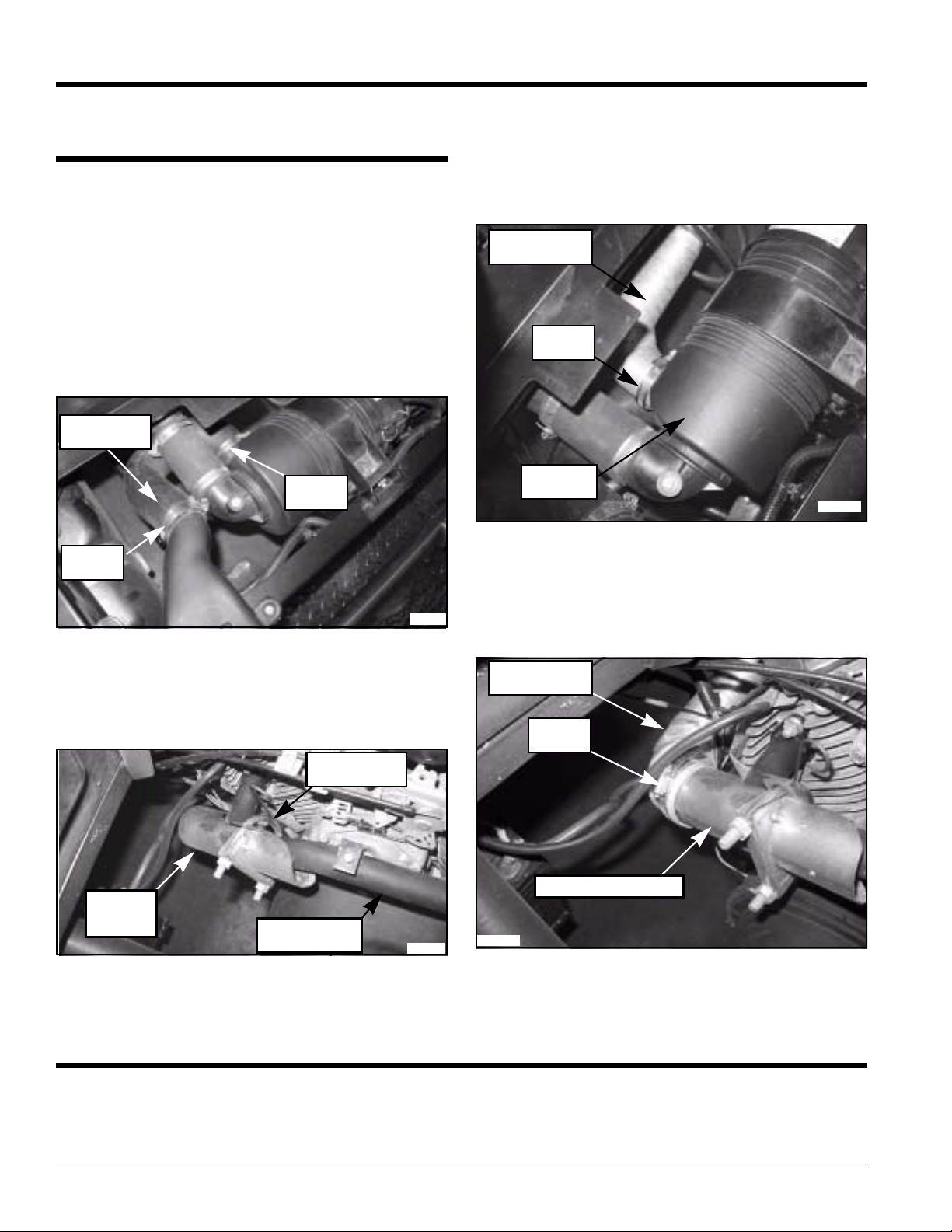
Refer to Figure 7:
1. Loosenthetwostainlesssteelhoseclampssecuring
the air intake hose.
2. Remove air intake hose and save for later
reinstallation when warmer weather prevails.
Air Intake
Hose
SS Hose
Clamp
SS Hose
Clamp
23804
Figure 7
Refer to Figure 7:
3. Install heat gather ing shield over the engine exhaust
manifold at the 90 degree bend as shown.
4. Secure with muffler clamp, flat bar, and two nuts.
Muffler Clamp
Flat Bar
Refer to Figure 9:
5. Obtainflexiblealuminumtubeand,takingcare not to
deform it, expand the tube to approximately 14”.
Install one end on the canister air intake tube as
shown.
6. Secure in place with the stainless steel hose clamp.
Flexible
Aluminum Tube
SS Hose
Clamp
AirCleaner
Canister
23806
Figure 9
Refer to Figure 10:
7. Install the other end on the heat gathering shield as
shown.
8. Secure in place with the stainless steel hose clamp.
Flexible
Aluminum Tube
SS Hose
Clamp
Heat
Gathering
Shield
Engine Exhaust
Manifold
Figure 8
23805
23807
Heat Gathering Shield
Figure 10
Treker 4210/4410 ST Series Engine Cold W eather Kit Part No. 701-074A
Qty. Part No. Part Description
1 701-075M MANUAL - ENGINE COLD WEATHER KIT
1 700-204H HEAT GATHERING SHIELD
1 700-267D MUFFLER CLAMP FLAT BAR
1 700-272D 2" FLEXIBLE ALUMINUM TUBE 18.0" LG
2 800-259C HOSE CLAMP WRM DRV#36SS (1.81-2.75)
2
Manual No. 701-075M 11/23/05
■
Page 3

Land Pride
Assembly Instructions for 4200/4400 ST Trekers
Assembly Instructions f or
4200/4400 ST Trekers
Engine Cold Weather Kit No. 701-074A
General Information
Besuretoread all instructions and safety precautions on
page 1 before installing the Engine Cold Weather Kit.
Installation Instructions
Refer to Figure 4:
1. Release retaining clips two places on bottom of air
cleaner canister and remove air cleaner access
cover.
NOTE: It is not necessary to disconnect engine
snorkel.
Engine
Snorkel
5. Obtainflexiblealuminumtubeand,takingcare not to
deform it, expand the tube to approximately 14”.
Install one end on the heat gather ing shield and the
other end on the canister air intake tube.
6. Secure in place with the stainless steel hose clamps
as illustrated.
7. Reinstall the lower access cover to the air intake
canister.
8. Tighten driver’s side canister bolt.
Air Intake Tube
Before Rotation
Driver’s Side
Canister Bolt
214547
Figure 5
AirCleaner
Canister
Access Cover
Refer to Figure 5:
Retaining Clip
Figure 4
Engine
Snorkel Hose
21455
Flexible
Aluminum Tube
SS Hose
Clamp
SSHose
Clamp
2. Loosen driver’sside canister bolt and rotate canister
until air intake tube is facing diagonally toward left
front corner of the engine.
Refer to Figure 6:
3. Install heat gather ing shield over the engine exhaust
manifold at the 90 degree bend as shown.
4. Secure with muffler clamp, flat bar, and two nuts.
Heat
Gathering
Shield
Figure 6
Treker 4200/4400 ST Series Engine Cold W eather Kit Part No. 701-074A
Qty. Part No. Part Description
Air Filter
Intake Tube
Rotated
Muffler Clamp
Flat Bar
Engine Exhaust
Manifold
21453
1 701-075M MANUAL - ENGINE COLD WEATHER KIT
1 700-204H HEAT GATHERING SHIELD
1 700-267D MUFFLER CLAMP FLAT BAR
1 700-272D 2" FLEXIBLE ALUMINUM TUBE 18.0" LG
2 800-259C HOSE CLAMP WRM DRV#36SS (1.81-2.75)
11/23/05
■
Manual No. 701-075M
3
Page 4

Assembly Instructions for 4200/4400 NT Trekers
Land Pride
Assembly Instructions f or
4200/4400 NT Trekers
Engine Cold Weather Kit No. 701-073A
General Information
Besuretoread all instructions and safety precautions on
page 1 before installing the Engine Cold Weather Kit.
Installation Instructions
Refer to Figure 1:
1. Loosen the stainless steel Hose Clamps securing
the rubber air intake hose.
2. Remove rubber air intake hose and save for later
reinstallation when warmer weather prevails.
Refer to Figure 2 & Figure 3:
!
Caution: Make sure the flexible aluminum tube does not come
into contact with battery terminals. If necessary, secure the
aluminum air intake tube safely away from the battery with a
plastic tie strap.
3. Install heat gather ing shield over the engine exhaust
4. Secure with muffler clamp, flat bar, and two nuts.
CAUTION!
manifold at the 90 degree bend as shown.
5. Obtainflexiblealuminumtubeand,takingcare not to
deform it, expand the tube to approximately 40”.
Install one end on the heat gather ing shield and the
other end on the canister air intake tube.
6. Secure in place with the stainless steel hose clamps
as illustrated.
Engine Exhaust
Flexible
Aluminum Tube
SS Hose
Clamp
Heat
Gathering
Shield
Figure 2
Manifold
Muffler Clamp
Flat Bar
21457
Canister Air
Intake Tube
SS Hose
Clamp
AirCleaner
Canister
Battery
Terminals
Figure 3
AirCleaner
Canister
SS Hose
Clamp
Figure 1
Rubber Air
Intake Hose
21127
Treker 4200/4400 NT Series Engine Cold W eather Kit Part No. 701-073A
Qty. Part No. Part Description
1 701-075M MANUAL - ENGINE COLD WEATHER KIT
1 700-204H HEAT GATHERING SHIELD
1 700-267D MUFFLER CLAMP FLAT BAR
1 700-271D 2" FLEXIBLE ALUMINUM TUBE 36.0" LG
2 800-259C HOSE CLAMP WRM DRV#36SS (1.81-2.75)
Flexible
Aluminum Tube
21456
4
Manual No. 701-075M 11/23/05
■
 Loading...