

Page 1
Owner's Handbook
Publication Part No. LRL0650ENX
© Land Rover 2003
All rights reserved. No part of this publication may be reproduced, stored in a retrieval system or transmitted in any form, electronic, mechanical,
recording or other means without prior written permission from Land Rover.
As part of Land Rover environmental policy, this publication is printed on paper made from chlorine free pulp.
Page 2

Introduction
This handbook covers all current versions of Land Rover Discovery petrol and diesel models and,
together with the other books in your literature pack, provides information that you will need to
derive maximum pleasure from owning and driving your new vehicle.
For your convenience, the handbook is divided into sections, each dealing with a different aspect of
the vehicle. These are listed on the title page and you will find it worthwhile to take a little time to
read each one, and get to know your Discovery as soon as you possibly can. The more you
understand before you drive, the greater the satisfaction once you are seated behind the steering
wheel.
*An asterisk appearing within the text, identifies features or items of equipment that are either
optional, or are only fitted to some vehicles in the model range.
IMPORTANT
The specification of each vehicle will vary according to territorial requirements and also from model
to model within the vehicle range. Some of the information published in this handbook, therefore,
may not apply to your particular vehicle.
Land Rover operates a policy of constant product improvement and therefore reserves the right to change specifications without
notice at any time. Whilst every effort is made to ensure complete accuracy of the information in this handbook, no liabilities for
inaccuracies or the consequences thereof can be accepted by the manufacturer or the dealer, except in respect of personal injury
caused by the negligence of the manufacturer or the dealer.
2
Page 3

Contents
Quick Overview
FASCIA CONTROLS. . . . . . . . . . . . . . . . . . 5
INFORMATION SYSTEM . . . . . . . . . . . . . . 6
LIGHTS & INDICATORS. . . . . . . . . . . . . . . 7
WIPERS & WASHERS. . . . . . . . . . . . . . . . 8
BINNACLE SWITCHES. . . . . . . . . . . . . . . . 9
FASCIA SWITCHES . . . . . . . . . . . . . . . . . 10
AIR CONDITIONING CONTROLS . . . . . . . 11
AUDIO SYSTEM CONTROLS . . . . . . . . . . 12
NAVIGATION SYSTEM CONTROLS . . . . . 13
Filling Station Guide
FUEL FILLER . . . . . . . . . . . . . . . . . . . . . . 15
OPENING THE BONNET. . . . . . . . . . . . . . 15
TYRE PRESSURES . . . . . . . . . . . . . . . . . 16
Controls & Instruments
Keys & Handsets . . . . . . . . . . . . . . . . . . .27
Fascia Controls . . . . . . . . . . . . . . . . . . . . .28
Locks & Alarm . . . . . . . . . . . . . . . . . . . . .30
Seats . . . . . . . . . . . . . . . . . . . . . . . . . . . . .39
Seat Belts . . . . . . . . . . . . . . . . . . . . . . . . .48
Child Restraints . . . . . . . . . . . . . . . . . . . .52
Airbag SRS . . . . . . . . . . . . . . . . . . . . . . . .57
Steering Column . . . . . . . . . . . . . . . . . . . .61
Door Mirrors . . . . . . . . . . . . . . . . . . . . . . .62
Instruments . . . . . . . . . . . . . . . . . . . . . . .63
Warning Lights . . . . . . . . . . . . . . . . . . . . .65
Audible Warnings . . . . . . . . . . . . . . . . . . .70
Lights & Indicators . . . . . . . . . . . . . . . . . .71
Wipers & Washers . . . . . . . . . . . . . . . . . .75
Horn . . . . . . . . . . . . . . . . . . . . . . . . . . . . .78
Electric Windows . . . . . . . . . . . . . . . . . . .79
Sunroof . . . . . . . . . . . . . . . . . . . . . . . . . . .80
Heating & Ventilation . . . . . . . . . . . . . . . .82
Air Conditioning . . . . . . . . . . . . . . . . . . . .86
Heated Screens . . . . . . . . . . . . . . . . . . . . .91
Interior Equipment . . . . . . . . . . . . . . . . . .92
Rear Door & Step . . . . . . . . . . . . . . . . . .101
Loadspace Cover . . . . . . . . . . . . . . . . . .102
In-Car Telephones . . . . . . . . . . . . . . . . . .103
In-Car Entertainment . . . . . . . . . . . . . . . .104
Driving & Operating
Starting & Driving . . . . . . . . . . . . . . . . . .109
Catalytic Converter . . . . . . . . . . . . . . . . .115
Fuel Filling . . . . . . . . . . . . . . . . . . . . . . . .117
Manual Gearbox . . . . . . . . . . . . . . . . . . .121
Automatic Transmission . . . . . . . . . . . . .122
Transfer Gearbox . . . . . . . . . . . . . . . . . .125
Cruise Control . . . . . . . . . . . . . . . . . . . . .129
Brakes . . . . . . . . . . . . . . . . . . . . . . . . . . . 131
Traction Control . . . . . . . . . . . . . . . . . . .134
Hill Descent Control . . . . . . . . . . . . . . . .135
Active Cornering Enhancement . . . . . . . .137
Self-levelling Suspension . . . . . . . . . . . .139
Parking Aid System . . . . . . . . . . . . . . . .143
Towing . . . . . . . . . . . . . . . . . . . . . . . . . .144
Load Carrying . . . . . . . . . . . . . . . . . . . . .147
Page 4

Contents
Off-road Driving
Off-road Driving . . . . . . . . . . . . . . . . . . .151
Driving Techniques . . . . . . . . . . . . . . . . .155
Owner Maintenance
Maintenance . . . . . . . . . . . . . . . . . . . . . .165
Bonnet Opening . . . . . . . . . . . . . . . . . . .169
Engine Compartment . . . . . . . . . . . . . . .170
Engine Oil . . . . . . . . . . . . . . . . . . . . . . . .172
Cooling System . . . . . . . . . . . . . . . . . . . .174
Brakes . . . . . . . . . . . . . . . . . . . . . . . . . . .176
Power Steering . . . . . . . . . . . . . . . . . . . .177
Active Cornering Enhancement . . . . . . . .178
Washers . . . . . . . . . . . . . . . . . . . . . . . . .179
Wiper Blades . . . . . . . . . . . . . . . . . . . . . .181
Battery . . . . . . . . . . . . . . . . . . . . . . . . . . .182
Tyres . . . . . . . . . . . . . . . . . . . . . . . . . . . .185
Cleaning & Vehicle Care . . . . . . . . . . . . .188
Identification Numbers . . . . . . . . . . . . . .191
Parts & Accessories . . . . . . . . . . . . . . . .192
Emergency Information
Wheel Changing . . . . . . . . . . . . . . . . . . .197
Emergency Starting . . . . . . . . . . . . . . . . .204
Towing the Vehicle . . . . . . . . . . . . . . . . .207
Fuses . . . . . . . . . . . . . . . . . . . . . . . . . . . .209
Bulb Replacement . . . . . . . . . . . . . . . . . .216
Technical Data
Lubricants & Fluids . . . . . . . . . . . . . . . . .231
Capacities . . . . . . . . . . . . . . . . . . . . . . . .232
Engines . . . . . . . . . . . . . . . . . . . . . . . . . .233
Electrical & Steering . . . . . . . . . . . . . . . .235
Wheels & Tyres . . . . . . . . . . . . . . . . . . . .236
Vehicle Weights . . . . . . . . . . . . . . . . . . .238
Towing Weights . . . . . . . . . . . . . . . . . . .239
Dimensions . . . . . . . . . . . . . . . . . . . . . . .241
Towbar Dimensions . . . . . . . . . . . . . . . .242
Fuel Consumption . . . . . . . . . . . . . . . . . .243
Appendices . . . . . . . . . . . . . . . . . . . . . . .244
Page 5
Quick Overview
Quick Overview
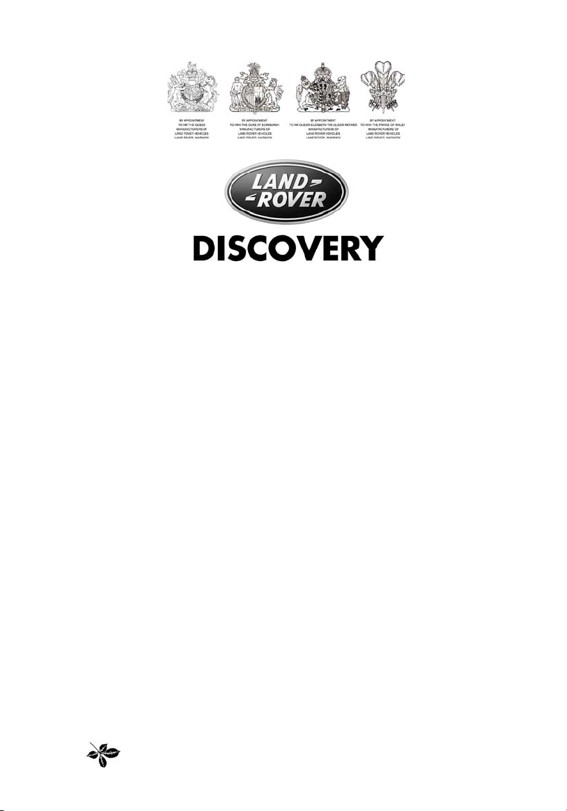
FASCIA CONTROLS
Quick Overview
23 41
5
789
6
H4872
1. Lighting and direction indicator controls
2. Cruise control switches
*
3. Windscreen wiper/washer controls
4. Heater/air conditioning controls
5. Transfer gear/differential lock* lever
NOTE: This is a brief overview of the fascia controls. For further details please refer to ‘FASCIA
CONTROLS’, page 28
6. Electric window switches
7. Fascia panel switches
8. Steering column height adjuster
9. Electric mirror adjuster
5
Page 6

INFORMATION SYSTEM
Quick Overview
321
4
5
8 7 6
H4977
1. Handbrake/low brake fluid (RED).
2. Low oil pressure (RED).
3. Battery charging (RED).
4. Supplemental restraint system - airbags
(RED).
5. Transmission oil temperature (RED)
6. Trip recorder reset button.
NOTE: If a warning light remains on or illuminates whilst driving, stop the vehicle and refer to the
relevant section of this handbook for advice.
NOTE: This is a brief overview of the warning lights, for more information concerning warning light
functionality, please refer to ‘WARNING LIGHTS’, page 65.
*.
7. Total distance (odometer) and trip
recorder.
NOTE: On automatic gearbox vehicles the
display also indicates the selector lever
position.
8. Anti-lock braking system (AMBER).
6
Page 7
Quick Overview
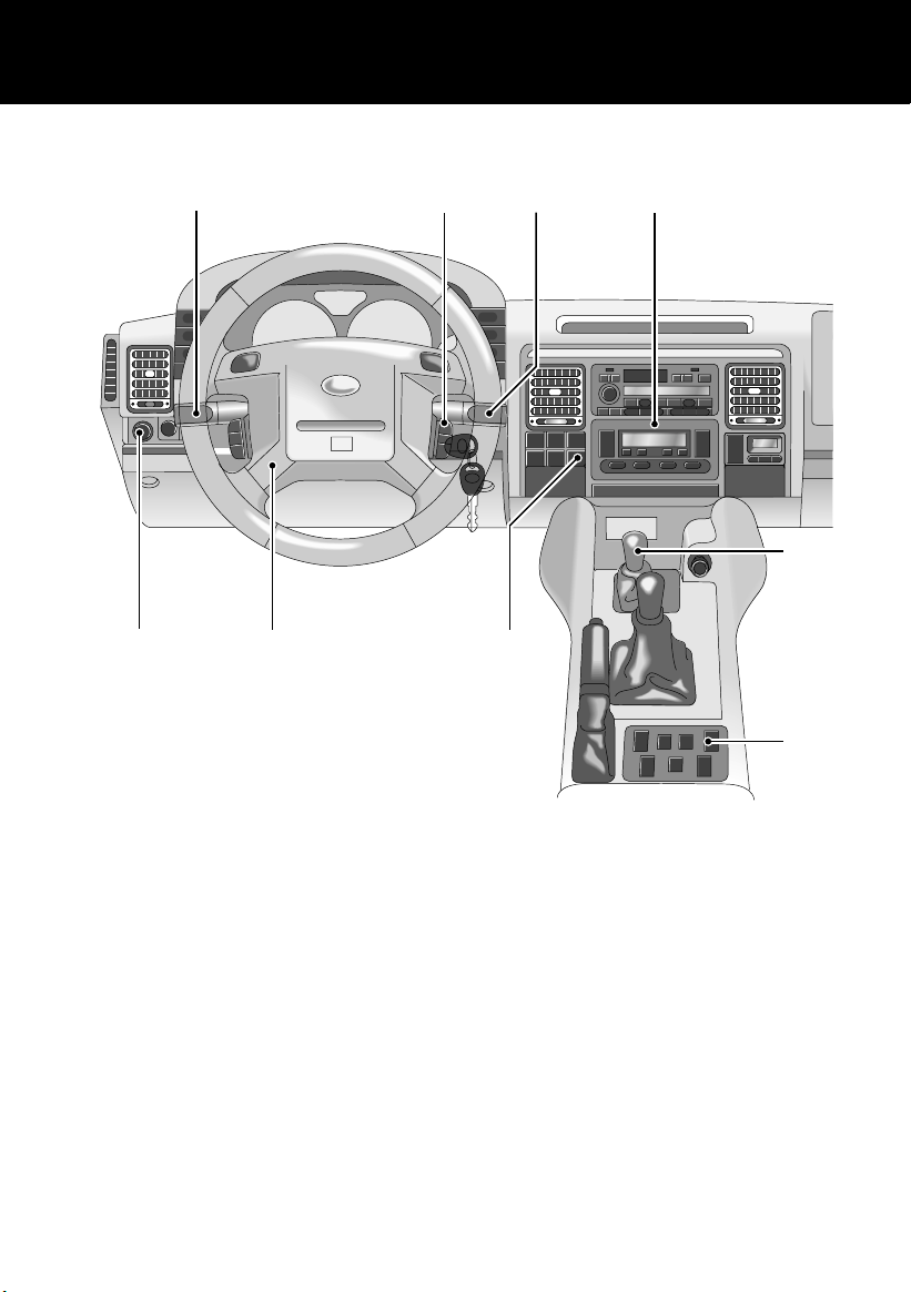
LIGHTS & INDICATORS
2
1
H2448
1. Side, tail and instrument panel lights
2. Headlights
Daylight running lights
The headlights illuminate automatically, when
the starter switch is turned to position ‘II’.
Headlight main and dipped beams
*
Direction indicators
H2582
Move the lever DOWN to indicate a LEFT turn,
and UP to indicate a RIGHT turn.
NOTE: For further information concerning
operation of the lights, please refer to
‘DIRECTION INDICATORS’, page 71 and
‘LIGHTS’, page 71.
H2449
Pull the lever fully towards the steering wheel to
change headlight beams.
To flash headlights, pull the lever part way up
and release.
7
Page 8
Quick Overview
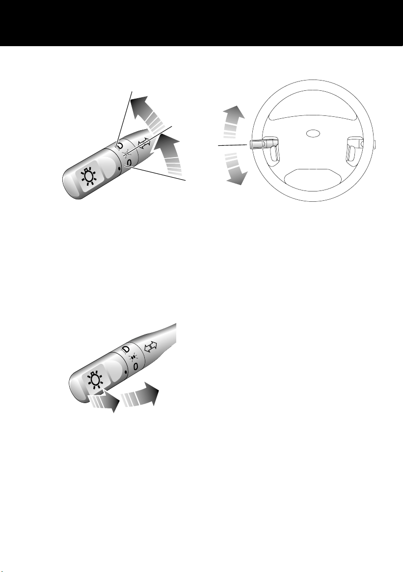
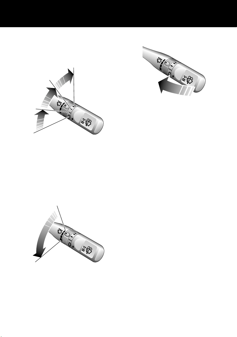
WIPERS & WASHERS
The wipers and washers will only operate when
the starter switch is turned to position ‘I’ or ‘II’.
3
2
1
H2450
1. Intermittent wipe
2. Normal speed wipe
3. Fast speed wipe
Single wipe
Pull the lever down and release immediately.
Variable delay (intermittent wipe)
Windscreen washers
H2452
Pull the lever towards the steering wheel. The
windscreen wipers will operate in conjunction
with the washers.
Headlight washers
When the headlights are illuminated, the
headlight washers operate automatically in
conjunction with every third operation of the
windscreen washers.
NOTE: For further information concerning
operation of the wipers and washers, please
refer to ‘WINDSCREEN WIPERS’, page 75.
*
H2451
Rotate the switch to vary the delay between
wipes.
8
Page 9
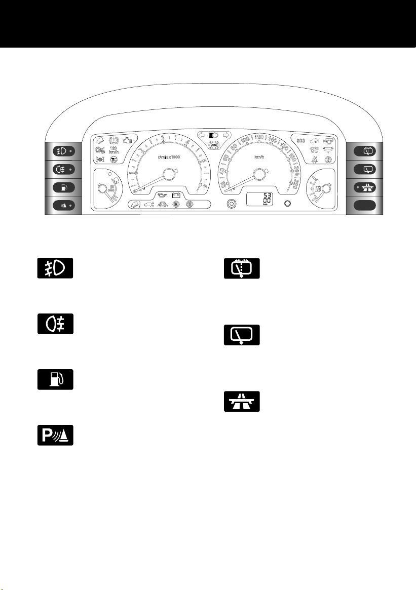
BINNACLE SWITCHES
P
H4439
Quick Overview
Front fog lights*
Operation and function of the front
fog lights are described under ‘FOG
LIGHTS’, page 73.
Rear fog guard lights
Operation and function of the rear
fog guard lights are described
under ‘FOG LIGHTS’, page 73.
Fuel flap release
Operation of the fuel flap release is
described under ‘FUEL FILLER’,
page 117.
Parking aid
Operation and function of the
parking aid system as described
under ‘USING THE PARKING AID
SYSTEM’, page 143
Rear window wash/wipe
The functions of the wash/wipe
switch are described under ‘REAR
WINDOW WIPER AND WASHER’,
page 77.
Rear window wiper
The functions of the rear window
wiper switch are described under
‘REAR WINDOW WIPER AND
WASHER’, page 77.
Cruise control
Operation and functions of the
cruise control switch are described
under ‘CRUISE CONTROL*’,
page 129.
9
Page 10

FASCIA SWITCHES
H4392
Hazard warning lights
Press to operate (see ‘HAZARD
WARNING LIGHTS’, page 74).
Heated front screen*
Press to operate (see ‘HEATED
FRONT SCREEN AND REAR
WINDOW’, page 91).
Quick Overview
Heated rear window
Press to operate (see‘HEATED
FRONT SCREEN AND REAR
WINDOW’, page 91).
Hill descent control (HDC)
Press to select hill descent control
(see ‘HILL DESCENT CONTROL’,
page 135).
Off-road suspension mode
Press to raise or lower the
suspension to or from off-road
height (see ‘SELF-LEVELLING
SUSPENSION*’, page 139).
*
10
Page 11
Quick Overview
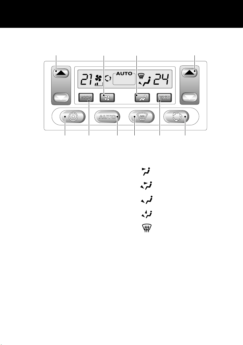
AIR CONDITIONING CONTROLS
2762
TEMP
H2481
1. Auto mode: Press for fully automatic
operation.
2. Temperature control: Press to set
individual left and right hand
temperatures.
3. Defrost mode: Press to defrost or demist
the windscreen.
4. Economy mode: Press to shut down the
air conditioning. The controls can then be
used as a conventional heater.
5. On/off control: Press to switch on or off.
6. Blower button: Press to adjust blower
speed.
NOTE: For more information concerning the operation of the climate control system, see ‘AIR
CONDITIONING CONTROLS’, page 87.
7. Air distribution control: Press the button
to adjust.
Face level vents
Foot and face level vents
Foot level vents
Foot level, windscreen and side
window vents
Windscreen and side window vents
8. External temperature: Press to display
the external temperature.
9. Air recirculation: Press to prohibit entry
of air from outside the vehicle - some
settings override recirculation after a
given time.
983145
11
Page 12
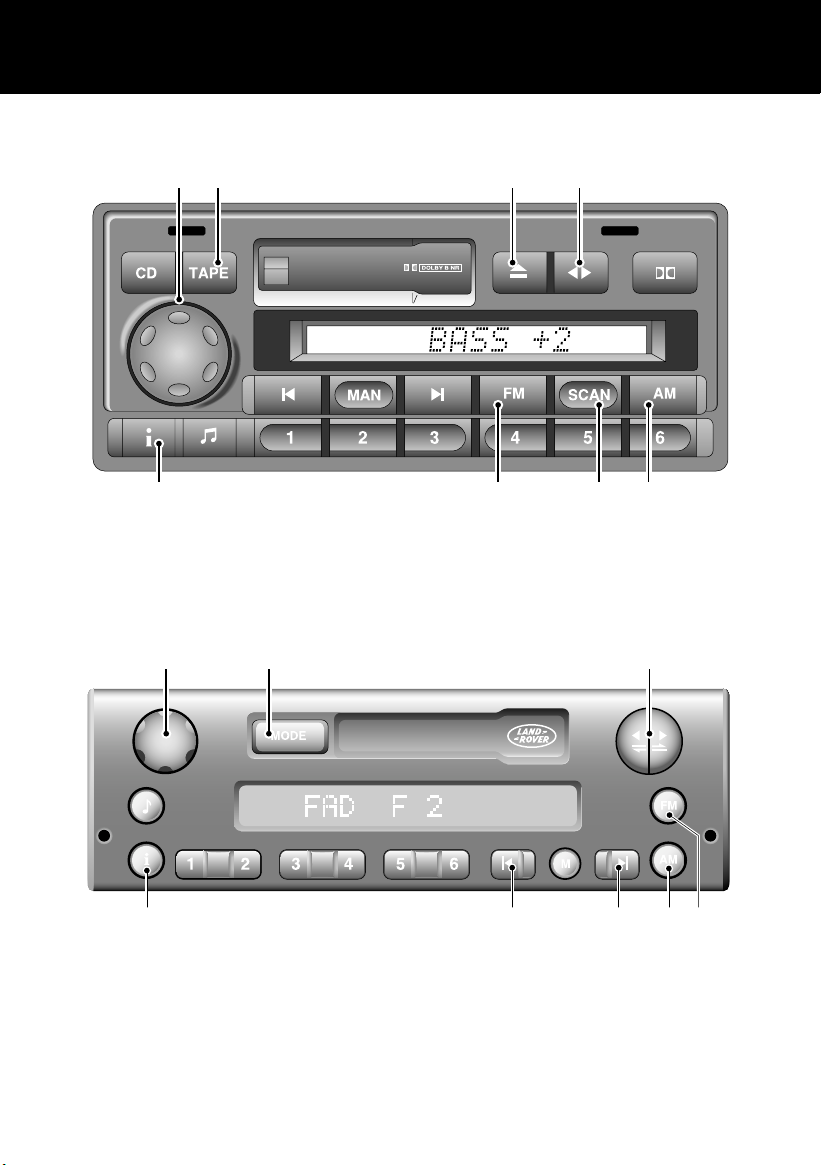
AUDIO SYSTEM CONTROLS
1 6 7 8
Quick Overview
TRAFFIC
NEWS
ICE 1332
5 4 32
1. On/off/volume control
2. FM selector
3. AM selector
4. Scan button
1 2 7
6
H4523
1. On/off/volume control
2. Mode (radio, tape, CD)
3. FM selector
4. AM selector
5. Traffic/news information
6. Tape mode
7. Eject
8. Tape reverse
55 4 3
5. Scan buttons
6. Traffic/news information
7. Tape controls
12
Page 13
Quick Overview
TP
CD
Rad
Nav
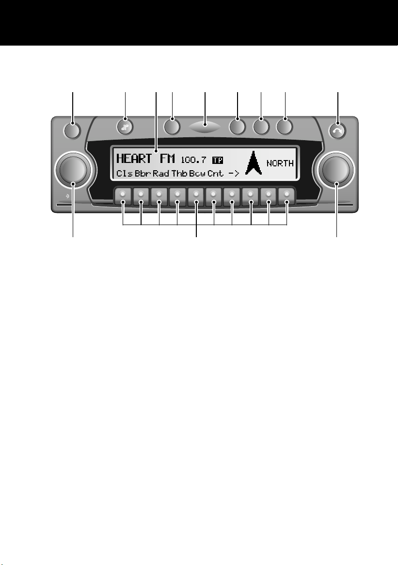
NAVIGATION SYSTEM CONTROLS
1 2 4 5 6 7 8 9
ON
Info
NAVISYS
3
TP
NAVIGATION SYSTEM
CD
Rad
Nav
OK
1112 10
ICE 0223
1. On/off
2. Tone
3. Display
4. Traffic programme
5. Security light
6. CD mode selection
NOTE: Please refer to your ‘In-Car Entertainment’ and ‘Navigation’ handbooks for further details.
7. Radio mode selection
8. Navigation mode selection
9. Display/CD eject
10. Right rotary control
11. Multifunction buttons
12. Left rotary/volume control
13
Page 14

Quick Overview
NOTE: Some music CD manufacturers are using data encryption to 'copy-protect' their recordings
and prevent the production of pirate copies. These CDs differ from the internationally agreed CD
audio standard, RedBook, a standard that serves as the operating basis for all CD players and
changers.
Copy-protected CDs may not play in your Audio unit or CD changer or may be played subject to
various limitations, e.g., sound quality may be impaired.
If you do experience a problem, try the CD in other players before contacting the CD vendor.
14
Page 15
Filling Station Guide
Filling Station Guide
Filling Station Guide
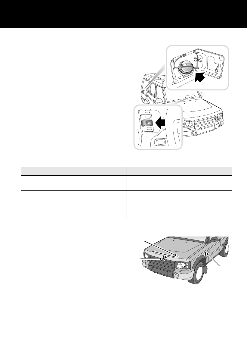
FUEL FILLER
The fuel filler is located in the rear right-hand
wing. With the starter switch turned to position
‘0’ or ‘I’, press the binnacle switch to release the
filler flap.
The filler cap is designed to allow the fuel tank
to vent during the first half turn. Carefully
loosen the cap one half turn until resistance is
felt, and allow fuel tank pressure to be released.
Once the pressure is released (hissing has
stopped), it is safe to fully remove the filler cap.
When replacing, tighten the cap clockwise until
you hear the fuel cap ratchet click at least three
times.
H5049
Fuel type
Diesel vehicles To EN590 specification.
NOT compatible with Bio-Diesel fuels
Petrol vehicles - high comp - cat conv
low comp - cat conv
low comp - non-cat conv
Unleaded 95 RON
Unleaded 91 RON
Unleaded 91 RON or 95 RON Leaded (where
only leaded available)
NOTE: For more detailed information, see ‘FUEL
FILLER’, page 117.
OPENING THE BONNET
1. From inside the vehicle, pull the bonnet
release handle located on the left-hand
side below the fascia.
2. Lift bonnet safety catch near centre of
under-bonnet.
3. Prop on support stay.
3
2
1
H5051
NOTE: For more detailed information, see
‘BONNET OPENING’, page 169.
15
Page 16
Filling Station Guide
Engine oil top up
Diesel vehicles Use Castrol 5W/30 engine oil meeting
specification ACEA A1+B1. If this is not
available, then oil meeting specification ACEA
A3+B3 can be used.
Petrol vehicles Use Castrol 10W/40 engine oil meeting
specification ACEA A2, If Castrol 10W/40 is
not available, Castrol 10W/30 can be used.
Cooling system top up
All vehicles 50% mix of fresh water and anti-freeze, see
‘LUBRICANTS AND FLUIDS’, page 231.
NOTE: For more detailed information, see
‘LUBRICANTS AND FLUIDS’, page 231.
TYRE PRESSURES
Air pressure naturally increases in warm tyres
(after the vehicle has been driven for a while). If
you have to check warm tyres, you should
expect the pressures to have increased between
30 and 40 kPa (4 to 6 lbf/in2). In this
circumstance, NEVER let air out of the tyres in
order to match the recommended pressures.
Loading condition
Pressure - kPa (lbf/in2)
Normal operating conditions Front 211 kPa (30 lbf/in2)
Rear 262 kPa (38 lbf/in
Vehicle loaded to maximum gross
vehicle weight
Front 211 kPa (30 lbf/in
Rear 322 kPa (46 lbf/in
NOTE: For more detailed information, see ‘WHEELS & TYRES’, page 236.
2
)
2
)
2
)
16
Page 17
Before You Drive
BEFORE YOU DRIVE . . . . . . . . . . . . . . . . . . . . . . 19
SYMBOLS USED . . . . . . . . . . . . . . . . . . . . . . . . . 19
WARNINGS IN THIS HANDBOOK. . . . . . . . . . . . . 20
SECURITY CARD . . . . . . . . . . . . . . . . . . . . . . . . . 20
SERVICE PORTFOLIO . . . . . . . . . . . . . . . . . . . . . 21
WARNING LABELS ATTACHED TO THE VEHICLE 21
GEARBOX SELECTOR LEVER LABELS. . . . . . . . . 22
SUN VISOR LABELS . . . . . . . . . . . . . . . . . . . . . . 22
IN AN EMERGENCY. . . . . . . . . . . . . . . . . . . . . . . 23
17
Page 18

18
Page 19

Before You Drive
Before You Drive
BEFORE YOU DRIVE
WARNING
Your vehicle has a higher ground clearance
and hence, a higher centre of gravity than
ordinary passenger cars. This will result in
different handling characteristics.
Inexperienced drivers should take additional
care, particularly in off-road driving
situations and when performing abrupt
manoeuvres on unstable surfaces.
SYMBOLS USED
The following symbols used within the
handbook call your attention to specific types of
information.
This recycling symbol identifies those
items that must be disposed of safely in
order to prevent unnecessary damage to the
environment.
This symbol identifies those features that
can be adjusted or disabled/enabled by a
Land Rover Dealer/Authorised Repairer
19
Page 20

Before You Drive
WARNINGS IN THIS HANDBOOK
WARNING
Safety warnings are included in this
handbook. These indicate either a procedure
which must be followed precisely, or
information that should be considered with
great care in order to avoid the possibility of
personal injury or serious damage to the
vehicle.
SECURITY CARD
The security card, supplied with the literature
pack, contains important emergency
information. It is ESSENTIAL that you keep the
card safe from theft and ensure that it is passed
to the new owner if you sell the vehicle.
• Key number: This is the number of the
starter/door key - essential if you ever need
to obtain a replacement.
• Emergency key access code: You will need
this code in order to start the vehicle if the
handset has been lost or damaged (see
‘Emergency key access’, page 34).
• Locking wheel nut number: If your vehicle
has locking wheel nuts, you will have been
provided with a special wheel nut socket to
remove them. You will need to quote this
number to obtain a replacement socket.
• VIN (vehicle identification number): This
identity number is unique to your vehicle
and is essential proof of its specification.
The number can also be found in various
locations around the vehicle (see ‘VEHICLE
IDENTIFICATION NUMBER (VIN)’,
page 191).
• Radio security code number: This unique
code must be entered into the radio
whenever the power supply has been
disconnected. Without this code, the radio
unit will not operate (see 'Security code' in
the 'In-Car Entertainment' book).
WARNING
Never leave the security card inside the
vehicle when it is unattended.
Memorise the emergency key access code, or
keep the card on your person while driving, in
case of emergencies.
20
Page 21

Before You Drive
SERVICE PORTFOLIO
The Service Portfolio book included in your
literature pack contains important vehicle
identification information, details of your
entitlement under the terms of the Land Rover
Warranty, as well as useful consumer advice.
Most important of all, however, is the section
on maintenance. This outlines the servicing
requirements for your vehicle and also includes
the service record slips, which the
Dealer/Authorised Repairer should sign and
stamp to certify that the routine services have
been carried out at the recommended intervals.
WARNING LABELS ATTACHED TO THE
VEHICLE
Warning labels attached to your vehicle
bearing this symbol mean: DO NOT
touch or adjust components until you
have read the relevant instructions in
the handbook.
Warning labels showing this symbol
indicate that the ignition system utilises
very high voltages. DO NOT touch any
ignition components while the starter
switch is turned on!
21
Page 22
Before You Drive
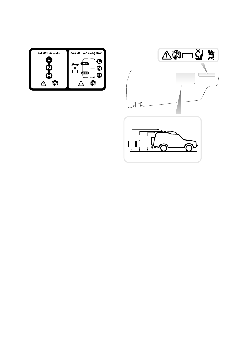
GEARBOX SELECTOR LEVER LABELS
H4931
Information concerning operation of the
transfer gearbox is printed on the centre
console. This is important information and
must be understood fully with reference to
‘TRANSFER GEARBOX’, page 125, before using
the transfer gearbox.
SUN VISOR LABELS
AIRBAG
SRS
1980
1940
2015
mm
mm
mm
78.0
79.5
76.5
INS
INS
INS
H2545
Always take careful note of warning information
about the airbag SRS attached to the sun visor
(illustrated above) or other parts of the vehicle.
Details of the vehicle's standard ride height,
both with and without an open sunroof are
printed on the driver’s sun visor.
22
Page 23

Before You Drive
IN AN EMERGENCY
IMPORTANT INFORMATION
Remember the breakdown safety code
If a breakdown occurs while travelling:
• Wherever possible, consistent with
road safety and traffic conditions, the
vehicle should be moved off the main
thoroughfare, preferably into a lay-by. If
a breakdown occurs on a motorway,
pull well over to the inside of the hard
shoulder.
• Switch on hazard lights.
• If possible, position a warning triangle
or a flashing amber light at an
appropriate distance from the vehicle to
warn other traffic of the breakdown,
(note the legal requirements of some
countries).
• Consider evacuating passengers
through nearside doors onto the verge,
as a precaution in case your vehicle is
accidentally struck by other traffic.
23
Page 24

24
Page 25
Controls & Instruments
Keys & Handsets
KEYS AND HANDSETS. . . . . . . . . . . . . . . . . . . . . 27
Fascia Controls
FASCIA CONTROLS . . . . . . . . . . . . . . . . . . . . . . . 28
Locks & Alarm
ALARM SYSTEM . . . . . . . . . . . . . . . . . . . . . . . . . 30
ENGINE IMMOBILISATION . . . . . . . . . . . . . . . . . 34
REMOTE HANDSET BATTERY . . . . . . . . . . . . . . . 36
CHILD-PROOF LOCKS . . . . . . . . . . . . . . . . . . . . . 37
DOOR LOCKING CUT-OFF SWITCH . . . . . . . . . . . 38
Seats
MANUALLY OPERATED FRONT SEATS. . . . . . . . 39
POWER OPERATED FRONT SEATS . . . . . . . . . . . 41
HEAD RESTRAINTS. . . . . . . . . . . . . . . . . . . . . . . 43
FOLDING ARMRESTS . . . . . . . . . . . . . . . . . . . . . 43
HEATED FRONT SEATS . . . . . . . . . . . . . . . . . . . . 44
FOLDING THE REAR SEATS. . . . . . . . . . . . . . . . . 44
OCCASIONAL REAR SEATS. . . . . . . . . . . . . . . . . 45
Seat Belts
SEAT BELT SAFETY . . . . . . . . . . . . . . . . . . . . . . . 48
PREGNANT WOMEN . . . . . . . . . . . . . . . . . . . . . . 49
SEAT BELTS. . . . . . . . . . . . . . . . . . . . . . . . . . . . . 49
SEAT BELT PRE-TENSIONERS . . . . . . . . . . . . . . 50
CARING FOR SEAT BELTS. . . . . . . . . . . . . . . . . . 51
Child Restraints
CHILD SAFETY SEATS. . . . . . . . . . . . . . . . . . . . . 52
ISOFIX CHILD RESTRAINTS . . . . . . . . . . . . . . . . 53
TETHER STRAP ANCHORAGES. . . . . . . . . . . . . . 55
Airbag SRS
AIRBAG SRS . . . . . . . . . . . . . . . . . . . . . . . . . . . . 57
HOW THE AIRBAG SRS WORKS . . . . . . . . . . . . . 58
SERVICE INFORMATION . . . . . . . . . . . . . . . . . . . 60
Steering Column
STEERING COLUMN ADJUSTMENT . . . . . . . . . . 61
Door Mirrors
EXTERIOR MIRRORS. . . . . . . . . . . . . . . . . . . . . . 62
25
Page 26

Instruments
INSTRUMENT PANEL . . . . . . . . . . . . . . . . . . . . . 63
Warning Lights
WARNING LIGHTS . . . . . . . . . . . . . . . . . . . . . . . 65
Audible Warnings
AUDIBLE WARNINGS . . . . . . . . . . . . . . . . . . . . . 70
Lights & Indicators
DIRECTION INDICATORS . . . . . . . . . . . . . . . . . . 71
LIGHTS . . . . . . . . . . . . . . . . . . . . . . . . . . . . . . . . 71
FOG LIGHTS . . . . . . . . . . . . . . . . . . . . . . . . . . . . 73
HAZARD WARNING LIGHTS. . . . . . . . . . . . . . . . 74
Wipers & Washers
OPERATING . . . . . . . . . . . . . . . . . . . . . . . . . . . . 75
WINDSCREEN WIPERS . . . . . . . . . . . . . . . . . . . 75
WINDSCREEN WASHER. . . . . . . . . . . . . . . . . . . 76
HEADLIGHT WASHERS . . . . . . . . . . . . . . . . . . . 77
REAR WINDOW WIPER AND WASHER . . . . . . . 77
Horn
HORN . . . . . . . . . . . . . . . . . . . . . . . . . . . . . . . . . 78
Electric Windows
ELECTRIC WINDOW CONTROLS . . . . . . . . . . . . 79
Sunroof
ELECTRIC SUNROOF . . . . . . . . . . . . . . . . . . . . . 80
CIGAR LIGHTER . . . . . . . . . . . . . . . . . . . . . . . . . 95
ASHTRAYS . . . . . . . . . . . . . . . . . . . . . . . . . . . . . 95
CD AUTOCHANGER . . . . . . . . . . . . . . . . . . . . . . 96
AUXILIARY POWER SOCKET . . . . . . . . . . . . . . . 97
CUP HOLDERS . . . . . . . . . . . . . . . . . . . . . . . . . . 97
CUBBY BOX . . . . . . . . . . . . . . . . . . . . . . . . . . . . 99
SUN VISOR VANITY MIRROR ILLUMINATION . . 99
INTERIOR REAR-VIEW MIRROR . . . . . . . . . . . 100
Rear Door & Step
REAR DOOR . . . . . . . . . . . . . . . . . . . . . . . . . . . 101
REAR STEP. . . . . . . . . . . . . . . . . . . . . . . . . . . . 101
Loadspace Cover
LOADSPACE COVER . . . . . . . . . . . . . . . . . . . . . 102
In-Car Telephones
IN-CAR TELEPHONES. . . . . . . . . . . . . . . . . . . . 103
In-Car Entertainment
RADIO AERIAL . . . . . . . . . . . . . . . . . . . . . . . . . 104
IN-CAR ENTERTAINMENT . . . . . . . . . . . . . . . . 104
HEADPHONE CONTROLS . . . . . . . . . . . . . . . . . 105
RADIO REMOTE CONTROLS. . . . . . . . . . . . . . . 106
Heating & Ventilation
VENTILATION . . . . . . . . . . . . . . . . . . . . . . . . . . . 82
HEATER CONTROLS. . . . . . . . . . . . . . . . . . . . . . 83
USING YOUR HEATER . . . . . . . . . . . . . . . . . . . . 84
Air Conditioning
VENTILATION . . . . . . . . . . . . . . . . . . . . . . . . . . . 86
AIR CONDITIONING CONTROLS. . . . . . . . . . . . . 87
GENERAL NOTES . . . . . . . . . . . . . . . . . . . . . . . . 90
Heated Screens
HEATED FRONT SCREEN AND REAR WINDOW . 91
Interior Equipment
FRONT INTERIOR & LOADSPACE LIGHTS . . . . . 92
REAR INTERIOR LIGHTS . . . . . . . . . . . . . . . . . . 92
GLOVEBOX LIGHT . . . . . . . . . . . . . . . . . . . . . . . 93
CLOCK . . . . . . . . . . . . . . . . . . . . . . . . . . . . . . . . 93
COIN TRAY . . . . . . . . . . . . . . . . . . . . . . . . . . . . . 94
26
Page 27
Keys & Handsets
Controls & Instruments
Keys & Handsets
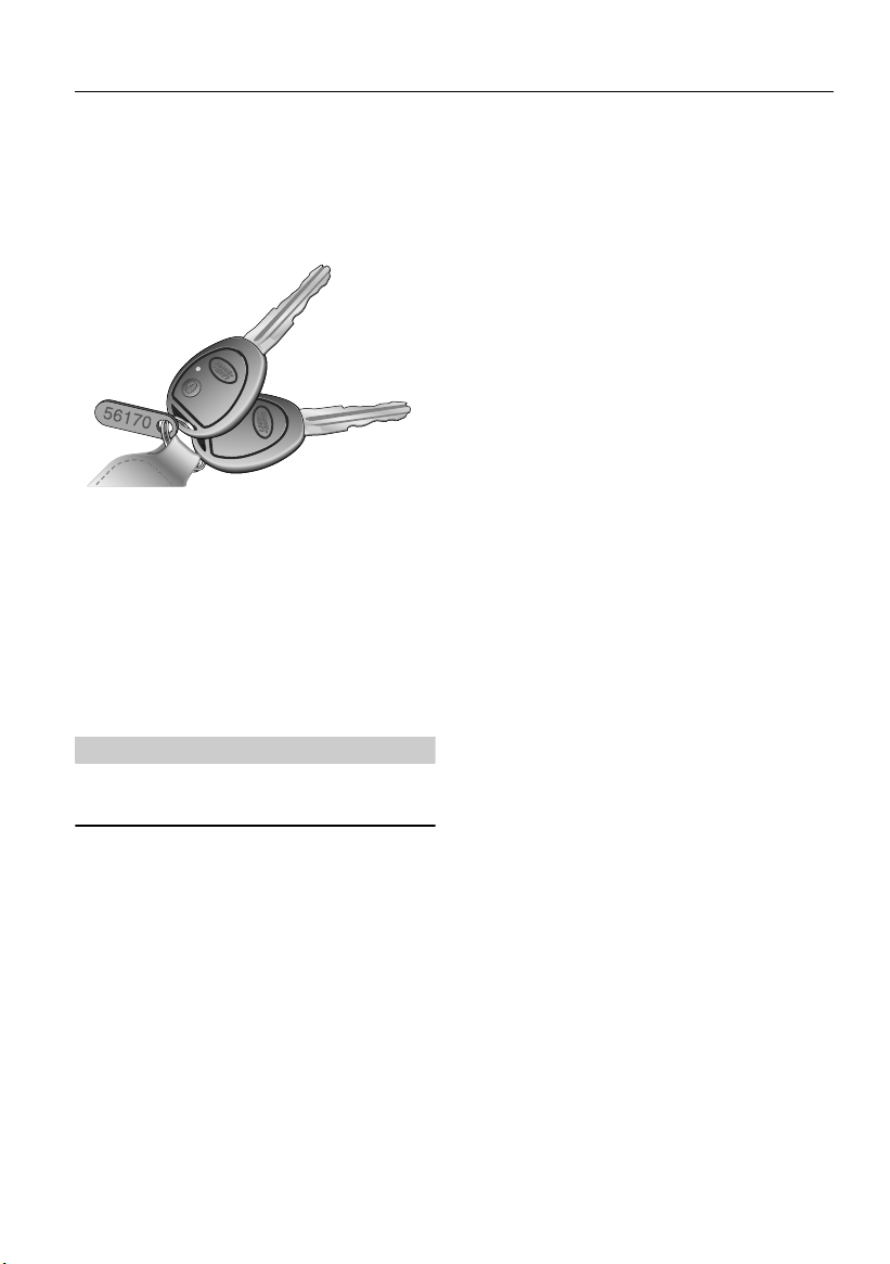
KEYS AND HANDSETS
You have been supplied with two remote
handsets with integral keys which operate all
locks.
H5032
The key number is stamped on a tag attached to
the key ring. Check that the key number has
been entered in the space provided on your
Security card.
If the remote handset is lost, contact a Land
Rover Dealer/Authorised Repairer, who can
supply replacement units.
WARNING
Keep the Security card and spare handset in a
safe place - NOT IN THE VEHICLE!
27
Page 28
Fascia Controls
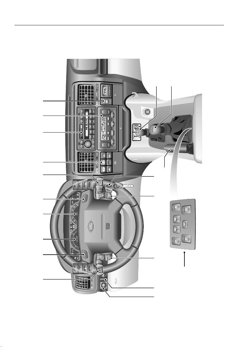
FASCIA CONTROLS
10
987652 43
Fascia Controls
TRAFFIC
NEWS
11
12
13
P
P
19
1
18 17 1416 15
H5009
28
Page 29

Fascia Controls
Fascia Controls Key
1. Lighting and direction indicator controls
2. Horn switch
3. Tachometer
4. Speedometer
5. Horn switch
6. Windscreen wiper/washer controls
7. Fascia panel switches
8. Audio system controls
9. Heater/air conditioning controls
10. Door locking switch
11. Transfer gear/differential lock lever
12. Main gear lever
13. Handbrake
14. Starter switch
15. Cruise control switches
16. Remote radio controls*
17. Headlamp levelling control*
18. Electric mirror adjuster
19. Electric window switches
NOTE: The precise specification and location of
the controls may vary according to territorial
requirements and from model to model within
the vehicle range.
*
*
29
Page 30
Locks & Alarm
Locks & Alarm
ALARM SYSTEM
Your vehicle is fitted with a sophisticated
electronic anti-theft alarm and engine
immobilisation system. There are also a
number of additional security features, some of
which are selectable options and some are
standard features of the vehicle. In order to
ensure maximum security and operating
convenience, you are strongly advised to gain a
full understanding of the features and
alternatives available, by thoroughly reading
this section of the handbook.
IMPORTANT INFORMATION
FOR MAXIMUM SECURITY ALWAYS
SUPERLOCK THE VEHICLE USING THE
REMOTE HANDSET (except when
passengers are to be left inside or if it is
necessary to leave a window or sunroof
open).
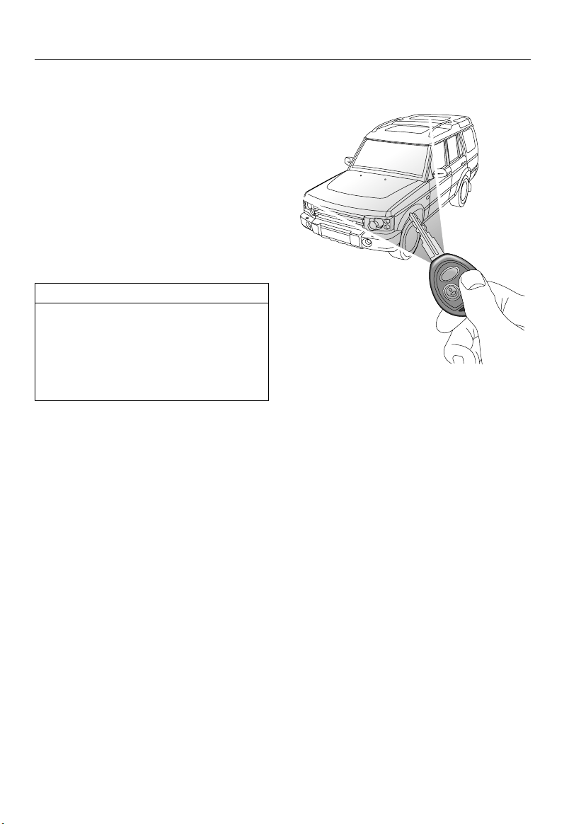
Using the remote handset
H4402
While it is not necessary to point the handset at
the vehicle, the handset must be within range of
the vehicle when a button is pressed. Note that
the operating range may vary depending upon
handset battery condition and may sometimes
be limited by physical and geographical factors
beyond your control. From a security point of
view, it may not be wise to unlock unless you
are within a few feet of the vehicle.
Locking
With the remote handset:
Press the lock (padlock symbol) button once:
• all doors are superlocked (see
‘Superlocking’, page 31)
• engine immobilised
• perimetric alarm activated (protects the
doors, bonnet and taildoor)
• interior space protection
The direction indicator lights flash three times
to confirm that the vehicle is secure and the
anti-theft alarm indicator light (in the
instrument panel) starts to flash.
30
* activated
Page 31

Locks & Alarm
With the key:
Insert the key and turn the door lock towards
the rear of the vehicle:
• all doors locked (not superlocked)
• engine immobilised
• perimetric alarm activated (protects the
doors, bonnet and taildoor)
• NO INTERIOR SPACE PROTECTION
The direction indicator lights flash once to
confirm that the vehicle is secure and the
anti-theft alarm indicator light (in the
instrument panel) starts to flash.
Unlocking
With the remote handset:
• Press the unlock (Land Rover) button once
to disarm the alarm and unlock the driver's
door only (see ‘Single point entry’,
page 32).
• Press the unlock button twice to disarm the
alarm and unlock ALL the doors.
In either case, the direction indicator lights
flash once and the interior lights illuminate.
With the key:
While the doors can be unlocked using the key,
this method is NOT RECOMMENDED depending on the specification of the vehicle
the alarm may not be disarmed.
NOTE: If the handset does not operate after the
vehicle has been parked for a long period,
unlock the driver's door with the key and then
try again. If the handset still fails to operate,
enter the EKA code, see ‘Emergency key
access’, page 34.
Superlocking
Provided all the doors are fully closed, the
Superlocking feature is activated automatically
whenever the vehicle is locked using the remote
handset. Superlocking immobilises the interior
door handles, thereby preventing an intruder
from gaining entry by smashing a window and
reaching inside the vehicle to operate the door
handles.
Note that locking with the key will not activate
superlocking.
WARNING
For safety, NEVER use Superlocking if
passengers are to remain inside the vehicle in an emergency they would not be able to
escape. Also, any movement from within the
vehicle would activate the alarm, if interior
space protection has been activated
Anti-theft alarm indicator light
H2546
This light provides information about the status
of the alarm system, as follows:
When the vehicle is locked:
The light flashes rapidly while the alarm is
arming itself. After ten seconds, the light
adjusts to a slower frequency and continues to
flash as an anti-theft deterrent until the alarm is
disarmed.
If the engine is immobilised (even though the
alarm has been disarmed):
The light flashes slowly until the engine is
remobilised.
31
Page 32

Locks & Alarm
If the alarm has been triggered:
The light will flash rapidly when the alarm is
disarmed until the starter switch is turned to
position II.
If the remote handset battery power is low:
The light will flash rapidly for ten seconds after
the handset has been used when the driver's
door is opened.
Mislock
If the driver's door is not fully closed when the
handset lock button is pressed, the alarm
sounder or vehicle horn will sound once,
indicating a mislock. In this case, none of the
doors will lock and the alarm system will not be
armed.
If a passenger door or other aperture is not fully
closed when the handset lock button is
pressed, the alarm sounder or vehicle horn will
sound once, indicating a mislock. However, the
‘partial arming’ attributes of the security system
will enable as much of the system to be armed
as possible (all fully closed door or bonnet
apertures will be protected, but an open door
will not!). As soon as the open aperture is
closed, the system will automatically revert to a
fully armed state.
NOTE: If a mislock occurs as a result of an open
door, the superlocking and interior space
protection
Dealer/Authorised Repairer.
* features will not be activated.
The mislock audible warning can be
disabled by a Land Rover
To silence the alarm, press either button on the
remote handset.
Headlight courtesy delay
When locking the vehicle, the remote handset
can be used to illuminate the headlights for
30 seconds. At night this will make it easier for
you to unlock the garage, or walk to your house
in safety. Operate this feature at the same time
as you lock the car, by keeping the handset
LOCK button pressed for more than 2 seconds
(the doors lock and alarm system arms in the
usual way).
To extinguish the lights before the 30-second
illumination period has expired, press the lock
button again.
The headlight courtesy delay can be
disabled by a Land Rover
Dealer/Authorised Repairer.
Single point entry
This is a personal security feature, which
enables the driver's door only to be unlocked,
leaving the other doors in a locked state. It can
be operated by the remote handset as follows:
• press the unlock button once to unlock the
driver's door.
• press a second time (within one minute) to
unlock the remaining doors.
Single point entry can be disabled by a
Land Rover Dealer/Authorised Repairer.
If the alarm sounds
If the alarm is triggered, the alarm sounder or
vehicle horn will sound for 30 seconds before
switching off and resetting itself to the same
protection status that existed prior to the alarm
being triggered.
32
Page 33

Locks & Alarm
Interior locking switch
H4403
This is a personal security feature which allows
the driver to lock (or unlock) all the doors from
inside the vehicle (while driving or with the
vehicle stationary). Press the lower part of the
switch to lock (the alarm will not be armed),
and the upper part to unlock.
NOTE: If the locks have already been
superlocked, the switch will not release the
locks.
Interior door handles and door sill locking
buttons
From inside the vehicle, each door can be
individually locked by depressing the
appropriate door sill button. However, doors
cannot be unlocked by raising the sill button.
Use the door handles to unlock, as follows:
• First operation of the door handle unlocks
the door.
• Second operation of the door handle opens
the door.
Interior space protection
H2468
Interior space protection is designed to protect
the interior of the vehicle from intrusion (entry
by a thief through a smashed window, for
example). Two pairs of sensors monitor the
interior space and activate the alarm if air
movement is detected in the passenger
compartment.
Using the handset:
Interior space protection is activated
automatically whenever the remote handset is
used to set the alarm and can ONLY be
deactivated with the handset.
Key operation:
Using the key will NOT activate (or deactivate)
interior space protection.
NOTE: Interior space protection cannot be
activated if a door is open, or if the starter
switch is turned on.
*
WARNING
Never activate interior space protection if
windows or sunroof are to be left open, or if
passengers or animals are to be left inside
the vehicle - any movement will activate the
alarm.
33
Page 34

Locks & Alarm
Drive-away door locking
This security feature locks all the doors
automatically when the vehicle speed exceeds
7 km/h (4 mph), and unlocks the doors as soon
as the starter switch is turned off (provided the
doors had previously been locked by the
drive-away door locking feature).
Note that drive-away door locking is not
selectable by the driver, and that operation of
the door locks by any other means (interior
locking switch on the fascia panel, for example)
will disable the drive-away door locking
function for the remainder of the journey, or
until the starter switch is turned off and on
again.
Drive-away door locking can be selected
or deselected by a Land Rover
Dealer/Authorised Repairer.
ENGINE IMMOBILISATION
Engine immobilisation is an important aspect of
the security system and includes a feature
known as ‘passive immobilisation’. This is
designed to safeguard the vehicle from theft,
should the driver forget to lock the doors and
prevents the engine from being started unless
the GENUINE handset key is inserted into the
starter switch. Engine immobilisation is
automatic whenever any of the following
conditions occur.
• The vehicle is locked using handset or key.
• Thirty seconds after the starter switch has
been turned off AND the driver's door
opened.
• Five minutes after the starter switch is
turned off, or the alarm system is disarmed.
NOTE: The engine will be re-mobilised
automatically whenever the genuine handset
key is inserted into the starter switch and
turned to position ‘II’.
Emergency key access
If the handset is damaged, or fails to operate,
the engine can be re-mobilised by using the key
to enter a unique four number emergency key
access code. The code is recorded on the
Security Information card and is entered as
follows:
34
Page 35

Locks & Alarm
IMPORTANT INFORMATION
When entering a code:
• ENSURE each key movement is carried
out with care and precision and turned
to the full extent of its travel.
• After turning the key to either the lock
or unlock positions, make sure it is
FULLY returned to the centre (vertical)
position.
• An interval of 10 seconds or more
between key turns, or the key being
held in a locked or unlocked position
for 5 seconds or more will cancel an
entry attempt, in which case you must
start again with operation 1.
1. Ensure that all doors are
closed, then using the key turn
the driver's door lock to the
UNLOCK position (towards the
front of the car) and hold in
this position for at least
5 seconds until the alarm sounder sounds
once). Then return the key to the centre
position. It is now possible to use the key to
enter the separate numerical values of the four
numbers that make up the emergency key
access code.
2. Enter the FIRST number of
the code. If the first number is
4, turn the key (towards the
front of the car) to the UNLOCK
position 4 times. Ensure the
key is FULLY returned to the
centre position after each turn.
3. Enter the SECOND number
of the code. If the second
number is 3, turn the key
(towards the rear) to the LOCK
position 3 times. Remember;
the key must be FULLY
returned to the centre position after each turn.
4. Enter the THIRD number of
the code. If the third number is
12, turn the key to the UNLOCK
position twelve times,
ensuring that the key is FULLY
returned to the centre position
after each turn.
5. Enter the FOURTH number
of the code. If the fourth
number is 1, turn the key to the
LOCK position once. Ensure
the key is FULLY returned to
the centre position.
6. Finally, turn the key to the
UNLOCK position once more.
If the code has been entered
correctly, a double ‘bleep’ will
sound (a single ‘bleep’
indicates that the code has
been entered incorrectly).
NOTE: If the Mislock audible warning has been
deselected (by a Land Rover Dealer/Authorised
Repairer), the alarm sounder will not sound
when an EKA code has been entered. Instead,
the alarm indicator light on the instrument
panel will flash once (for one second) to
indicate a successful code entry.
There is now a five-minute delay before the
alarm and engine immobiliser are deactivated.
DO NOT OPEN THE DOOR OR ATTEMPT TO
ENTER THE VEHICLE YET!
35
Page 36

Locks & Alarm
7. Through the driver's door window, observe
the anti-theft alarm indicator light on the
instrument panel. If code entry was successful,
this light will continue flashing (once every two
seconds) for the five minute delay period.
DO NOT OPEN THE DOOR OR ATTEMPT TO
ENTER THE VEHICLE until the full delay period
has elapsed - this will be indicated by the
anti-theft alarm indicator light extinguishing.
8. Now open the door, insert the key into the
starter and turn the switch to position ‘II’
IMMEDIATELY! If the starter switch is not
turned to position ‘II’ within 30 seconds of the
indicator light extinguishing, the engine will
automatically immobilise again.
If an incorrect code has been entered:
If an incorrect code has been entered, the alarm
sounder will sound once and the anti-theft
alarm indicator light will continue to flash. In
this case, return to operation ‘1’ and re-enter
the code.
After three failed entry attempts, the security
system invokes a delay period of ten minutes
during which the system will not accept any
further attempts to enter a code.
REMOTE HANDSET BATTERY
The battery should last for approximately
three years dependent upon use. When the
battery needs replacing it will be apparent from
the following symptoms:
• A gradual deterioration in range and
performance.
• The alarm indicator light in the instrument
panel will flash rapidly for 10 seconds after
the driver's door is opened.
Always fit a Land Rover YWX10003L or a
Panasonic CR2032 replacement battery
(available from a Land Rover Dealer/Authorised
Repairer).
WARNING
The handset contains delicate electronic
circuits and must be protected from impact
and water damage, high temperatures and
humidity, direct sunlight and the effects of
solvents, waxes and abrasive cleaners.
IMPORTANT INFORMATION
Memorise the emergency key access code
or keep the Security card on your person in
case of emergencies. NEVER leave the card
in the vehicle.
36
Page 37

Locks & Alarm
Battery replacement
H2794
1. With the handset face down, insert the
blade of a small flat-bladed screwdriver
into the slot at the rear of the handset (see
inset) and prise the back upwards.
2. Insert the screwdriver blade as shown in
the right hand inset and then carefully
slide it along the joint towards the key to
release the back of the handset.
3. Use a small flat-bladed screwdriver to
prise the battery from its mounting (see
illustration), taking care to avoid touching
the circuit board or the metal battery
contacts.
4. Fit the new battery, ensuring that correct
polarity is maintained (‘+’ side facing up).
Finger marks will adversely affect battery
life; if possible, avoid touching the flat
surfaces of the battery and wipe them
clean before fitting.
5. Press the two halves of the handset firmly
together and ensure that both halves are
fully joined to prevent dirt or moisture
from entering the handset.
CHILD-PROOF LOCKS
H4405
Move the locking levers on the rear doors and
taildoor down to engage the child locks.
With the child-proof locks engaged, neither the
rear doors nor the taildoor can be opened from
inside the vehicle, thereby avoiding the risk of a
door being opened accidentally while the
vehicle is moving.
WARNING
NEVER leave children unsupervised in the
vehicle.
The handset is now ready for use.
37
Page 38

Locks & Alarm
DOOR LOCKING CUT-OFF SWITCH
H4406
An inertia switch, operational only with the
starter switch in position ‘II’ and the alarm
disarmed, prevents the doors centrally locking
(or if the doors are locked, will unlock them) in
the event of an accident or sudden impact.
When the switch operates, the direction
indicator lights flash (if market permits), until
the system is reset by turning the starter switch
on and off, and opening and closing the driver's
door.
Note that doors cannot be locked again until the
switch is reset.
The inertia switch also cuts off the fuel supply
(see ‘FUEL CUT-OFF SWITCH’, page 120).
WARNING
Always check for fuel leaks before resetting
the switch!
38
Page 39

Seats
Seats
MANUALLY OPERATED FRONT SEATS
WARNING
To avoid the risk of loss of control and
personal injury, DO NOT adjust the driver's
seat while the vehicle is in motion.
Sitting correctly
o
max. 30
H4692
The seats, head restraints, seat belts and
airbags all contribute to the protection of the
occupants. Optimal use of these components
will give you more protection. Therefore,
observe the following points:
• Sit in the most upright position with the
base of your spine as far back as possible
and the backrest not reclined more than
30 degrees.
• Adjust the head restraints so that the top of
the head restraint is level with the upper
portion of the head.
• Do not move the front seat too close to the
instrument panel. The drive r should hold the
steering wheel with slightly bent arms. The
legs should also be slightly bent so that the
pedals can be pressed to the floor.
• The seat belt should rest in the centre of the
shoulder. The lap part should fit tightly
across the hips and not on the stomach.
Forward/backward adjustment
H2547
Lift the lever to slide the seat forward or back.
Ensure the seat is locked in position before
driving.
39
Page 40

Seats
Seat back adjustment
H2548
Rotate the handwheel to achieve the desired
backrest angle.
WARNING
DO NOT travel with the seat backs reclined
steeply rearwards. Optimum benefit is
obtained from the seat belt with the seat back
angle set to approximately 30º from the
upright (vertical).
Lumbar support adjustment*
H2590
Rotate the handwheel to increase or decrease
support to the lumbar region of the back.
40
Page 41

Seats
POWER OPERATED FRONT SEATS*
WARNING
To avoid the risk of loss of control and
personal injury, DO NOT adjust the driver's
seat while the vehicle is in motion.
The seat adjustment controls are situated on
the side of the centrally mounted cubby box.
Seat adjustment is only possible when the
starter switch is turned to position ‘II’ or for
45 seconds after opening the driver's door.
Forward/backward adjustment
Seat cushion angle adjustment
H2469
Push and hold the switch forwards or
backwards to move the seat to the desired
position.
H2470
Twist the switch to tilt the seat cushion to the
desired position. Note that the front and rear of
the switch work independently - the front
raising or lowering the front of the cushion, the
rear of the switch similarly controlling the rear
of the seat cushion.
41
Page 42

Seats
Seat cushion height adjustment*
H2471
On some vehicles, the height of the seat
cushion can be adjusted. Push the switch up or
down to raise or lower the cushion.
Lumbar support adjustment*
Seat back adjustment
H2473
Twist the switch forward or backward until the
desired seat back angle is achieved.
WARNING
DO NOT travel with the seat backs reclined
steeply rearwards. Optimum benefit is
obtained from the seat belt with the seat back
angle set to approximately 30º from the
upright (vertical).
H2472
Push the switch up to increase support to the
lumbar region of the back. Lower the switch to
reduce lumbar support.
42
Page 43

Seats
HEAD RESTRAINTS
H2465
Pull the head restraint up or down until the
cushion is level with the back of the head.
WARNING
Head restraints are designed to support the
back of the head (NOT THE NECK), and to
restrain rearward movement of the head in
the event of a collision. The restraint must be
positioned level with the head to be effective.
FOLDING ARMRESTS*
H2553
Some vehicles are fitted with adjustable front
seat armrests, which can be either; stowed
vertically in line with the seat backrest when not
required, or folded horizontally to serve as an
arm/elbow rest.
The height/angle of each armrest can be
adjusted by turning the knob set into the end of
the armrest: clockwise to raise and
anti-clockwise to lower.
Head restraint removal
Turn both mounting collars fully anti-clockwise
and pull the restraint upwards to remove.
After replacing a head restraint turn the
mounting collars clockwise.
43
Page 44

Seats
HEATED FRONT SEATS*
H2517
With the starter switch turned on and the
engine running, press the switches to operate
the heating elements in either the driver's or
front passenger seat (the indicator light in the
switch illuminates). Press a second time to
switch off.
The seat heaters are thermostatically controlled
and operate intermittently to achieve and then
maintain a predetermined temperature between
26° and 36°C.
IMPORTANT INFORMATION
The seat heaters consume considerable
power from the battery. For this reason,
they should ONLY be operated while the
engine is running.
FOLDING THE REAR SEATS
H2493
WARNING
DO NOT adjust any part of a seat while the
vehicle is in motion.
One or both parts of the split rear seat can be
either partially or fully folded to further increase
the rear loadspace.
1. To release either part of the backrest, lift
the lever shown in the inset, and then fold
the backrest onto the seat base.
2. Ensure the outer head restraints are fully
lowered, the armrest is stowed and the
centre head restraint
3. To release the seat base, pull the release
strap upward (arrowed in illustration).
With backrest and seat base released, the
assembly can be folded forward as shown.
* is removed.
44
Page 45

Seats
Returning the seat to the upright position
H2549
Push the seat assembly back onto the floor - the
floor catches should latch with the base of the
seat. Then raise the backrest.
If the backrest cannot be raised easily, DO NOT
force it. This indicates that the seat base has not
fully engaged with the floor catches (note that
the seat assembly is designed to prevent the
backrest from being raised unless the seat is
properly secured to the floor).
With the seat base secure, the backrest can be
raised and locked in position (none of the RED
panel on the release lever should be visible
when the backrest is correctly latched).
WARNING
After the seat is returned to the upright
position, the latching mechanism should be
checked and physically tested to ensure that
both the seat base and backrest are secure
before driving.
OCCASIONAL REAR SEATS
WARNING
Before driving with passengers seated in the
occasional rear seats, for safety ensure that
the floor latches are fully engaged.
Do not carry passengers in the occasional
rear seats if a dog guard is fitted between the
second row of seats and the loadspace.
Erecting the seats
1
H3045
1. Push the lever (shown in inset) and hold to
release the seat from its stowed position.
2
H3046
2. Swing the seat away from the vehicle side,
at the same time lifting and turning it
towards the horizontal.
45
Page 46

Seats
4
3
H3047
3. Lower the seat to the loadspace floor,
PUSHING DOWN FIRMLY to ensure that
the floor latch has fully engaged.
4. Pull the backrest into the upright position.
NOTE: The backrest cannot be raised unless the
seat is securely latched to the floor.
IMPORTANT INFORMATION
Remember to unfold the head restraints
from the roof before driving.
Stowing the seats
NOTE: Before stowing a seat, ensure that the
drinks tray to the side of the seat has been
emptied, and that the seat belt buckle is folded
down to prevent it from becoming trapped
between the backrest and cushion.
2
1
H3049
1. Push the backrest release lever forward to
unlock the backrest.
2. Fold the backrest fully forward.
3
H3050
3. Turn the twist grip (moving part of the bar
on the back of the seat) fully forward to
release the floor latch, and start to lift the
seat from the loadspace floor.
46
Page 47

Seats
4
H3051
4. Continue lifting, at the same time turning
the seat into a vertical position.
5
H3052
5. Push the seat firmly into the vehicle side,
ensuring that the seat has engaged fully
with the securing catch.
Head restraints
NOTE: The head restraints for use with the
occasional rear seats are hinged from the roof.
H3544
1. To unfold a head restraint, pull the handle
(arrowed in illustration) forward and
swing the restraint down from the roof.
Stow the head restraint when not in use by
pushing it back flush with the roof.
WARNING
DO NOT drive with occupants in the
occasional rear seats unless the head
restraints are unfolded.
WARNING
It is extremely dangerous to ride in the cargo
area. In a collision, anyone riding in this area
is more likely to be injured or killed. Do not
allow anyone to ride in any area of your
vehicle that is not equipped with seats and
safety belts. Be sure that everyone in your
vehicle is in a seat and using a safety belt
properly.
47
Page 48

Seat Belts
Seat Belts
SEAT BELT SAFETY
The seat belts fitted to the front and second row
seats are intended for use by adult sized
occupants. Each belt should be used by one
occupant only.
Observe the following precautions:
• DO make sure ALL passengers are securely
strapped in at all times - even for the
shortest journeys.
• ALWAYS adjust seat belts to eliminate any
slack in the webbing. DO NOT slacken the
webbing by holding the belt away from the
body - to be fully effective, the seat belt
must remain in full contact with the body at
all times.
• ALWAYS fit the lap strap as low on the hips
as possible (never across the abdomen),
and ensure that the diagonal belt passes
across the shoulder without slipping off or
pressing on the neck.
• DO NOT use a seat belt that is twisted or
obstructed in any way that could impede its
smooth operation.
• DO NOT wear seat belts over hard, sharp or
fragile items in clothing, such as pens, keys,
spectacles etc.
• DO NOT allow front seat occupants to travel
with the seat backs reclined steeply
rearwards. Optimum benefit is obtained
from the seat belt with the seat back angle
set to approximately 30º from the upright
(vertical) position.
• Always replace a seat belt assembly that has
withstood the strain of a severe vehicle
impact, or if the webbing shows signs of
fraying.
• Where possible use the seat belts to secure
large items of luggage that are to be carried
on the seats - in the event of an accident,
insecure items become flying missiles
capable of causing serious injury.
• DO NOT allow foreign matter (particularly
sugary food and drink particles) to enter the
seat belt locks - such substances can render
the locks inoperative.
• In most countries, all occupants are
required by law to wear a seat belt, unless
they have been issued with a medical
exemption certificate.
WARNING
The airbag supplementary restraint system
(SRS) is designed to add to the overall
effectiveness of the seat belts. It does not
replace them. SEAT BELTS MUST ALWAYS BE
WORN!
Ensure that all seat belts are worn correctly an improperly worn seat belt increases the
risk of death or serious injury in the event of a
collision.
48
Page 49

Seat Belts
PREGNANT WOMEN
WARNING
Pregnant women must wear a correctly
positioned seat belt; it is safer for mother and
unborn child.
There are many ways that the belt can be
misused for the sake of comfort, but there is
only one way of wearing it safely.
During pregnancy, women should wear the lap
belt across the hips below the baby, with the
diagonal belt passing across the shoulder,
between the breasts and to one side of the baby
- if in doubt, consult a doctor.
H5157
SEAT BELTS
To minimise injury in the event of an accident,
it is important that seat belts are worn correctly.
Read the instructions below and the advice
contained under the heading ‘SEAT BELT
SAFETY’.
Fastening the seat belts
H2488
Inertia reel belts are fitted to all front and rear
seating positions, and also to the occasional
rear seats*.
Never place anything between you and the seat
belt in an attempt to cushion the impact in the
event of an accident. It can be dangerous and
reduce the effectiveness of the seat belt in
preventing injury.
Pull the belt over the shoulder and across the
chest and, ensuring that the webbing is not
twisted, insert the metal tongue plate into the
buckle nearest the wearer - a ‘CLICK’ indicates
that the belt is securely locked.
Seat belts are designed to bear upon the bony
structure of the body (pelvis, chest and
shoulders) and can only be worn safely with the
seats in a normal upright position - DO NOT
allow front seat occupants to travel with the
seat steeply reclined.
Releasing the belt
Press the RED button on the seat belt buckle.
49
Page 50

Seat Belts
Upper anchorage adjustment (front seats
only)
H2491
The height of the seat belt upper anchorage can
be adjusted for comfort AND safety. Squeeze
the control between finger and thumb to raise
or lower the anchorage. For safety, the seat belt
should always be worn with the webbing
crossing the shoulder MIDWAY BETWEEN THE
NECK AND THE EDGE OF THE SHOULDER.
Ensure the anchorage has ‘clicked’ into one of
the locked positions before driving and DO NOT
adjust the height once the vehicle is in motion.
Where possible, rear seat passengers should
adjust their position on the seat to enable the
seat belt webbing to cross the shoulder without
pressing on the neck.
SEAT BELT PRE-TENSIONERS
The seat belt pre-tensioners activate in
conjunction with the airbag SRS and provide
additional protection in the event of a severe
frontal impact on the vehicle (see ‘HOW THE
AIRBAG SRS WORKS’, page 58). The
pre-tensioners automatically retract the seat
belts fitted to the front seats. This reduces any
slack in both the lap and diagonal portions of
the belts, thereby reducing forward movement
of the belt wearer in the event of a severe frontal
collision.
The airbag SRS warning light on the instrument
panel will alert you to any malfunction of the
seat belt pre-tensioners.
If the pre-tensioners have been activated, the
seat belts will still function as restraints, and
must be worn in the event that the vehicle
remains in a driveable condition.
NOTE: The seat belt pre-tensioners will NOT be
activated by rear, side or minor frontal impacts.
WARNING
•
The seat belt pre-tensioners will only be
activated once and then MUST BE
REPLACED by a Land Rover
Dealer/Authorised Repairer. Failure to
replace the pre-tensioners will reduce the
efficiency of the vehicle’s front restraint
system.
•
After any frontal impact, always have the
seat belts and pre-tensioners checked
and, if necessary, replaced by a Land
Rover Dealer/Authorised Repairer.
•
In the interests of safety, it is
recommended that removal and
replacement of the front seats and seat
belts should only be carried out by a Land
Rover Dealer/Authorised Repairer.
50
Page 51

Seat Belts
Service information
WARNING
DO NOT attempt to service, repair, replace,
modify or tamper with any part of the
pre-tensioner and airbag SRS, or wiring in the
vicinity of a pre-tensioner or airbag SRS
component; this could cause the system to
activate, resulting in personal injury.
After fifteen years from the original date of
registration (or the installation date of a
replacement pre-tensioners), some
components will need to be replaced by a Land
Rover Dealer/Authorised Repairer (note the
‘Seat belt pre-tensioner replacement date’
shown on page 2 of the Service Portfolio book).
In addition, ALWAYS contact your Land Rover
Dealer/Authorised Repairer if:
• an airbag inflates.
• a pre-tensioner activates.
• the front or side of the vehicle is damaged,
even if the pre-tensioner has not activated.
CARING FOR SEAT BELTS
Regularly inspect the belt webbing for signs of
fraying, cuts and wear; also pay particular
attention to the condition of the fixing points
and adjusters.
DO NOT bleach or dye the webbing and avoid
contaminating the webbing with polish, oil or
chemicals (see ‘CLEANING THE INTERIOR’,
page 189).
Testing inertia reel belts
• With the seat belt fastened, give the
webbing near the buckle a quick upward
pull. The buckle must remain securely
locked.
• With the seat belt unfastened, unreel the
webbing to the limit of its travel. Check that
unreeling is free from snatches and snags
and then allow the belt to FULLY retract.
• Partially unreel the webbing, then hold the
tongue plate and give it a quick forward pull.
The mechanism must lock automatically
and prevent any further unreeling.
If a seat belt should fail any of these tests,
contact your Dealer/Authorised Repairer
immediately.
WARNING
Always replace a seat belt that shows signs of
webbing damage or has withstood the strain
of a severe vehicle impact.
51
Page 52

Child Restraints
Child Restraints
CHILD SAFETY SEATS
Seat belts fitted to your vehicle are designed for
adults and larger children. For their safety, it is
very important that all infants and children
under 12 are restrained in a suitable child safety
seat appropriate to their age and size (see
table). Child safety seats approved for use in
your vehicle are available from Land Rover
Dealers/Authorised Repairers.
Only fit a child safety seat of a type approved for
the specific seating positions in your vehicle
(see table), and ensure the seat manufacturer’s
fitting instructions are followed exactly.
Vehicles fitted with a passenger airbag
For optimum safety, children should travel in
the rear of the vehicle at all times; front
passenger seat travel is NOT recommended.
However, if a passenger airbag is fitted and it is
essential that a child travel in the front, set the
seat fully rearward and seat the child in an
approved, FORWARD FACING child seat. DO
NOT use a rear facing child seat - an inflating
airbag could impact with the seat and cause
serious injury to the child!
The above symbol affixed to the passenger side
fascia panel of your vehicle, warns against the
use of a REAR FACING child seat in the front
passenger seat, when a passenger airbag is
fitted. This type of child seat could cause
serious injury to a child in the event of an airbag
deployment.
WARNING
DO NOT install a rearward facing child seat in
a passenger seat equipped with an airbag
system. Failure to follow this advice could
result in serious injury, or even death for the
child in the event of airbag deployment.
Mass Group
As indicated on child safety seat
packaging.
0 = Up to 10 kg (0-9 months) X U U X
0+ = Up to 13 kg (0-18 months) X U U X
I = 9 to 18 kg (9 months - 4 years) X U U X
II & III =15 to 36 kg (4-12 years) X U U X
U = Suitable for ‘universal’ category restraints approved for this mass group.
X = Seat position not suitable for children in this mass group.
* = Unsuitable for use with many child restraints due to the limited space between the 2nd and
3rd row seats. Smaller forward facing restraints and booster cushions may safely be used in
these positions if a good fit of the child restraint can be achieved following the manufacturers
instructions.
Front
Passenger
Seating Positions
Second Ro w
Outboard
52
Second
Row Centre
Third Row
Seats*
Page 53

Child Restraints
Seat belt locking mechanism
All front passenger and second row seat belts
have a special locking mechanism which aids
the retention of child seats. The procedure to
install a child seat is as follows:
1. Install the child seat in the vehicle, attach
the seat belt and secure the buckle in
accordance with the manufacturers fitting
instructions.
2. Pull on the shoulder section of the belt to
unreel all of the remaining webbing to the
limit of its travel. This will engage the
automatic locking feature, which then acts
as a ratchet, allowing the webbing to
retract ONLY.
3. Allow the seat belt to retract onto the child
seat (a ‘clicking’ sound will confirm that
the ratchet has engaged), firmly pushing
the child seat into the seat.
4. Ensure there is no slack in the seat belt by
pulling upwards on the shoulder belt
immediately above the child restraint. The
seat belt should now be locked and the
child seat held firmly in position.
Once the child seat is removed and all the seat
belt webbing is allowed to retract, the seat belt
locking mechanism reverts to normal
operation.
ISOFIX CHILD RESTRAINTS*
In some markets, child restraint systems
complying with International Standard
Organisation (ISO) regulations and approved
for fitting in your vehicle may be available.
These restraints are different to conventional
child seats, requiring anchor bars built into the
vehicle seat in order to accept the ISOFIX
locking mechanism.
NOTE: The automatic locking mechanism
should also be used when securing large items
of luggage to a seat.
53
Page 54

Child Restraints
Fitting ISOFIX child restraints
ISOFIX child restraints should only be fitted in
the two outer seating positions of the second
row seats. Anchor bars built into the rear seat
frame enable the ISOFIX restraints to be
securely attached to the vehicle seat in these
positions only. The anchor bar locations are
shown in the illustration.
When fitting ISOFIX child restraints, always
follow the instructions supplied by the
manufacturer of the restraint.
Once the ISOFIX restraint is installed, you are
recommended to test the security of the
installation before seating the child. Attempt to
twist the restraint from side to side and to pull
the restraint away from the vehicle seat; then
check that the anchors are still securely in
place.
If the restraint is not correctly anchored, there
is a significant risk of injury to the child in the
event of a collision or emergency braking.
WARNING
H4945
Both outer, rear (second row) seating positions
in your vehicle are equipped to accept ISOFIX
restraints.
WARNING
DO NOT attempt to fit ISOFIX restraints to the
centre seating position - the anchor bars are
not designed to hold an ISOFIX restraint in
this position.
54
Page 55

Child Restraints
TETHER STRAP ANCHORAGES
H3587
There are three tether strap anchorage points.
These should be used to attach tether straps
from child seats or restraint systems. Two
anchorage points are fitted to the back of the
second row seat, these should be used for the
two outer seating positions. A third single
anchorage point is located in the centre of the
rear header rail (above the tail door) for
attaching a tether strap from the centre seat
position. The anchorage points are shown in
the accompanying illustrations.
H3586
Provision is made for the fitting of up to three
child seats or restraint systems in the rear
(second row) seats, of the type that require
tether strap anchorage points.
WARNING
Child restraint anchorages are designed to
withstand only those loads imposed by
correctly fitted child restraints. Under no
circumstances should they be used for adult
rear seat belts or for harnesses for attaching
other items or equipment to the vehicle.
55
Page 56

Child Restraints
Attaching tether straps
1. Install the child restraint securely in one of
the second row seating positions.
2. Pass the tether strap over the back of the
vehicle seat and beneath the underside of
the head restraint.
3. Attach the clip on the head of the tether
strap to the tether anchor on the back of
the vehicle seat (or, for the centre seating
position, on the header rail above the
taildoor).
4. Tighten the tether strap according to the
manufacturer’s instruct ions to remove any
slack in the webbing.
WARNING
•
Always follow the child seat or restraint
system manufacturer’s instructions when
fitting tether straps.
•
When fitting a child seat or restraint
system, always pass the tether strap over
the top of the seat back and beneath the
underside of the head restraint.
•
If a child seat or restraint system is to be
fitted to the centre seating position, the
centre armrest must be in the stowed
position (folded into the seat).
56
Page 57

Airbag SRS
Airbag SRS
H4409
AIRBAG SRS
The airbag supplementary restraint system
(SRS) provides additional protection for either
the driver, or the driver and front seat
passenger, in the event of a severe frontal
impact on the vehicle.
WARNING
The airbag is a supplementary restraint
system that provides ADDITIONAL protection
in a severe frontal impact only - it does NOT
replace the need to wear a seat belt. For
maximum safety protection in all crash
situations, a seat belt must be worn.
Provided the front seat occupants are correctly
seated, with seat belts properly worn, the
airbags will provide additional protection to the
chest and facial areas in the event of the car
receiving a severe frontal impact.
NOTE: Inflation and deflation of the airbags
takes place very quickly and will not protect
against the effects of secondary impacts that
may occur.
The airbag(s) are located in the centre pad of
the steering wheel and, where fitted, in the
fascia panel above the glovebox.
WARNING
Do not allow a front seat passenger to
obstruct the operation of the airbag by placing
feet, knees or any other part of the person, or
any other objects in contact with, or in close
proximity to, an airbag module.
57
Page 58

Airbag SRS
WARNING
DO NOT attach or position items on or to an
airbag cover (steering wheel centre pad or
fascia panel), which could interfere with the
inflation of the airbag or, if the airbag
inflates, be propelled inside the car causing
injury to the occupants.
To ensure correct deployment of the airbags, it
is essential that obstructions are not allowed to
intervene between an airbag and the occupant.
The following are examples of the type of
obstructions that could either, impede correct
operation of the airbags, or jeopardise personal
safety in the event of an airbag deployment:
• Accessories attached to or obscuring an
airbag cover.
• Items of hand luggage, or other objects
placed on an airbag cover.
• Feet, knees or any other part of the anatomy
in contact with, or in close proximity to, an
airbag cover.
Seating positions
In order to provide optimum protection in the
event of a severe frontal impact, it is necessary
for the airbags to deploy with considerable
speed.
An inflating airbag can cause facial abrasions
and other injuries if the occupant is too close to
the airbag at the time of its deployment.
HOW THE AIRBAG SRS WORKS
In the event of a severe frontal impact, the
airbag control unit monitors the rate of
deceleration or acceleration induced by the
collision, to determine whether the airbags
should be deployed.
Operation of the airbag SRS is dependent
entirely on the rate at which the vehicle's
passenger compartment changes speed as a
result of a collision. The circumstances
affecting different collisions (vehicle speed,
angle of impact, type and size of object hit, for
example), vary considerably and will affect the
rate of acceleration or deceleration accordingly.
NOTE: The airbag SRS is not designed to
operate as a result of rear collisions, minor
frontal or side Impacts, roll over accidents; nor
will it operate as a result of heavy braking or
driving over bumps and potholes.
It follows, therefore, that significant superficial
damage can occur without the airbags
deploying or, conversely, that a relatively small
amount of structural damage may cause the
airbags to be deployed.
NOTE: Airbags will only deploy when they are
required to supplement the restraining force of
the seat belts.
In the case of a severe frontal collision, both
front airbags and seat belt pre-tensioners will
be deployed.
WARNING
To minimise the risk of accidental Injury from
inflating airbags, seat belts should be
correctly worn at all times. In addition, both
driver and front seat passenger should adjust
their seat to provide the maximum practical
distance from the airbags.
58
Page 59

Airbag SRS
H4939
Airbag inflation is virtually instantaneous and
occurs with considerable force, accompanied
by a loud noise. The inflated bag, together with
the seat belt restraint system, limit the
movement of a front seat occupant, thereby
reducing the risk of injury to the head and upper
torso.
WARNING
An inflating airbag can cause facial abrasions
and other injuries. Minimise the risk of injury
by ensuring that front seat occupants are
wearing their seat belts and are seated
correctly, with the seat as far back as is
practical.
WARNING
After inflation, some airbag components are
hot - DO NOT touch until they have cooled.
Airbag SRS warning light
A warning light mounted on the instrument
panel will alert you to any malfunction of the
airbag SRS. The airbag SRS should always be
checked by a Land Rover Dealer/Authorised
Repairer if any of the following symptoms
occur:
• The warning light fails to illuminate when
the starter switch is turned to position ‘II’.
• The warning light fails to extinguish within
approximately four seconds after the starter
switch is turned to position ‘II’.
• The warning light illuminates after the
engine is started, or while the vehicle is
being driven.
When an airbag inflates, a fine powder is
released. This is not an indication of a
malfunction, however, the powder may cause
irritation to the skin and should be thoroughly
flushed from the eyes and any cuts or abrasions
of the skin. After inflation the airbags deflate
immediately. This provides a gradual
cushioning effect for the occupant and also
ensures that the driver's forward vision is not
impaired.
59
Page 60

Airbag SRS
SERVICE INFORMATION
WARNING
DO NOT attempt to service, repair, replace,
modify or tamper with any part of the airbag
SRS, or wiring in the vicinity of an airbag SRS
component; this could cause the system to
activate, resulting in personal injury.
After ten years from the original date of
registration (or the installation date of a
replacement airbag SRS), some components
will need to be replaced by a Land Rover
Dealer/Authorised Repairer (note the ‘airbag
module replacement date’ shown on page 2 of
the Service Portfolio book).
In addition, ALWAYS contact your
Dealer/Authorised Repairer if:
• an airbag inflates.
• the front of the vehicle is damaged, even if
the airbag has not inflated.
• any part of an airbag module cover (the
steering wheel centre pad or fascia panel)
shows signs of cracking or damage.
IMPORTANT INFORMATION
The components that make up the airbag
SRS are sensitive to electrical or physical
interference, either of which could easily
damage the system and cause inadvertent
operation or a malfunction of the airbag.
For your safety it is recommended that you
seek the assistance of a Land Rover
Dealer/Authorised Repairer to carry out
any of the following:
• Removal or repair of any wiring or
component in the vicinity of any of the
SRS components (yellow wiring
harness), including the steering wheel,
steering column, instrument and fascia
panels.
• Installation of electronic equipment
such as a mobile phone, two-way radio
or in-car entertainment system.
• Modification to the front of the vehicle,
including the bumper and chassis.
• Attachment of accessories to the front
of the vehicle.
Disposing of vehicles
If you sell your vehicle, be sure to inform the
new owner that the vehicle has an airbag SRS.
In addition, make sure the new owner is aware
of the airbag module replacement date shown
on page 2 of the Service Portfolio book.
If your vehicle is to be scrapped; uninflated
airbags are potentially very dangerous and
must be safely deployed in a controlled
environment by qualified personnel, before a
vehicle is scrapped.
60
Page 61

Steering Column
Steering Column
STEERING COLUMN ADJUSTMENT
WARNING
DO NOT adjust the steering column while the
vehicle is in motion. This is extremely
dangerous!
DO NOT drive the vehicle unless the locking
lever is in the locked position.
H2533
The angle of the steering column can be
adjusted to suit your driving position:
1. With the vehicle stationary, push the
locking lever up and hold in this position.
2. Move the steering wheel (up or down) into
the desired position, making sure the
instrument panel is clearly visible.
3. When adjustment is complete, release the
locking lever to lock the steering column
in position.
61
Page 62

Door Mirrors
Door Mirrors
EXTERIOR MIRRORS
NOTE: Objects viewed in exterior mirrors may
appear further away than they actually are.
H2629
• Turn the control to the ‘L’ or ‘R’ position to
select either the left or right hand mirror.
• With the starter switch turned to position
‘II’, push the control in the appropriate
direction to tilt the mirror glass up/down/left
or right.
• When adjustment is complete, return the
control to the OFF position (midway
between ‘L’ and ‘R’).
NOTE: The door mirrors have integral heating
elements which disperse ice or mist from the
glass. These will operate in conjunction with the
heated rear window.
Folding the mirror body
The door mirrors are designed to fold forwards
or rearwards on impact. They can also be folded
back towards the side windows into a ‘park’
position to enable the vehicle to negotiate
narrower openings.
H2981
Operation: Mirror folding is carried out as
follows:
1. Ensure the mirror control is turned to the
centre position.
2. With the starter switch turned to position
‘II’, push the control down once to fold the
mirrors back towards the side windows.
3. Before driving, push the control down a
second time to return the mirrors to their
normal (extended) position.
If the mirrors are accidentally knocked out of
position (i.e. with one mirror extended and the
other in the ‘parked’ position), an additional
operation of the switch will re-synchronise
them.
62
Page 63

Instruments
Instruments
INSTRUMENT PANEL
2 3
1 4 5 6
H4395
1. Temperature gauge
Once the engine coolant has reached its normal
operating temperature, the pointer will rise to a
position within the WHITE segment of the
gauge (the precise position will vary according
to climatic conditions).
If the pointer moves towards the RED segment,
this indicates that the engine coolant is
becoming too hot. Should the pointer move
INTO the RED segment and the RED warning
light within the gauge illuminates, severe
engine damage could occur (under these
circumstances, the air conditioning may switch
off and engine performance may reduce in
order to minimise engine load).
Stop the vehicle as soon as safety permits and
allow the engine to idle for five minutes in order
to cool down - DO NOT SWITCH OFF. Seek
qualified assistance before continuing.
2. Tachometer
Indicates engine speed in revolutions per
minute (x 1000). In normal driving conditions
the engine is most fuel efficient between 2000
and 3000 rev/min.
Vehicles equipped with a catalytic converter are
fitted with a system which automatically
restricts the number of engine revolutions per
minute once the engine's maximum ‘governed’
speed has been reached.
3. Speedometer
Indicates road speed in kilometres per hour.
63
Page 64

Instruments
4. Total distance (odometer) and trip recorder
With the starter switch turned to position ‘II’,
the display indicates the total distance travelled
by the vehicle, and also shows the most recent
individual journey distance.In some markets,
the display can be set to show either miles or
kilometres. To convert from one to another,
press and hold the trip recorder reset button for
more than two seconds.
NOTE: On automatic gearbox vehicles the
display also indicates which selector position is
selected.
5. Trip recorder reset button
Press briefly to return the trip recorder display
to zero.
6. Fuel gauge
The pointer drops to zero when the starter
switch is turned off, but quickly rises to show
the level of fuel in the tank when the switch is
turned to position ‘II’. After refuelling, the
gauge rapidly rises to reflect the increase of fuel
in the tank.
When the fuel remaining in the tank is a
minimum of 14 litres (3 gallons) on petrol
vehicles, or 9 litres (2 gallons) on diesel
vehicles, the AMBER low fuel warning light in
the fuel gauge illuminates. If the light
illuminates, refuel at the first opportunity.
The small arrow visible below the fuel pump
symbol on the gauge indicates the side of the
vehicle on which the fuel filler is located - a
useful reminder to help you position the vehicle
on the correct side of the forecourt pumps
before refuelling.
WARNING
NEVER allow petrol engined models to run out
of fuel (the resultant misfire may destroy the
catalytic converter).
64
Page 65

Warning Lights
WARNING LIGHTS
H4398
Warning Lights
The location and specification of the warning
lights may vary according to model and market
requirements.
Hill descent control (HDC) ‘information’ GREEN
Illuminates briefly as a bulb and
system check when the starter
switch is turned to position 'II' and
also when HDC is selected.
If HDC is selected when Low Range gears are
engaged the light will illuminate continuously
indicating that HDC is active.
When HDC is selected and non-operating gears
are engaged (i.e. High range), the light will flash
to inform the driver that HDC is selected, but
will not operate.
If the light starts to flash while HDC is active,
normal functionality may seize and HDC ‘fade
out’ may be induced (see ‘HILL DESCENT
CONTROL’, page 135).
Handbrake, brake fluid - RED
The light illuminates for about
3 seconds as a bulb check when
the starter switch is turned on. It
also illuminates when the handbrake is applied
with the starter switch in position ‘II’.
The light should extinguish when the handbrake
is fully released or shortly after the electrical
circuits are switched on. If the light illuminates
whilst driving, a fault with the braking system is
indicated. Stop the vehicle as soon as safety
permits and seek qualified assistance before
continuing.
Check engine - AMBER
The light illuminates as a bulb and
system check when the starter
switch is turned on, and
extinguishes as soon as the engine is started.
Illumination at any other time indicates an
engine fault - if the light illuminates while
driving, avoid high speeds and seek qualified
assistance urgently.
*
65
Page 66

Warning Lights
Hi/Lo range- AMBER
Illuminates briefly as a bulb and
system check when the starter
switch is turned to position ‘II’ and
then extinguishes.
Illuminates continuously while the transfer
gearbox lever is in the neutral position.
Overspeed - RED*
Illuminates as a bulb check when
the starter switch is turned to
position ‘II’ and extinguishes after
approximately 2 seconds. The light will also
illuminate when the vehicle's road speed
exceeds 120 km/h and extinguishes again once
road speed drops below 120 km/h.
Differential lock warning light - AMBER*
Illuminates when the differential
lock is selected and remains
illuminated while the differential
lock is engaged.
It will only extinguish when the differential lock
actually disengages.
There will be a slight delay between differential
lock disengagement and the warning light bein g
extinguished, and is quite normal.
Three warning chimes will sound when
differential lock is engaged and disengaged.
NOTE: If the warning light is obviously reluctant
to extinguish after the differential lock has
disengaged, some transmission ‘wind-up’ may
be present.
Reversing the vehicle for a short distance and
then moving forward will usually ‘unwind’ the
transmission and the warning light will
extinguish, The vehicle can then be driven as
normal.
However, if after two or three attempts to
‘unwind’ the transmission, the light remains on,
consult your Dealer/Authorised Repairer AS
SOON AS POSSIBLE.
Traction Control - AMBER
Illuminates as a bulb check when
the starter switch is turned to
position ‘II’ and extinguishes after
approximately 3 seconds. The light illuminates
for a minimum of 2 seconds, whenever traction
control is operating.
If the light illuminates continuously, and
remains illuminated when the vehicle is
stationary, a fault with the system is indicated;
seek qualified assistance.
NOTE: Faults which cause the light to illuminate
after the initial system checks, or whilst driving,
will be accompanied by a warning chime
sounding three times.
Direction indicators - GREEN
The left or right warning light
flashes in time with the
corresponding left or right
direction indicator lights whenever they are
operated. If the warning light fails to flash, or
flashes very rapidly, this may indicate a bulb
failure in one of the direction indicator lights.
If the hazard switch is pressed, both warning
lights will flash in conjunction with the direction
indicator lights.
Headlight main beam - BLUE
Illuminates when the headlights
are switched to main beam.
66
Page 67

Warning Lights
Anti-lock braking system - AMBER
The light illuminates as a bulb and
system check when the starter
switch is turned to position ‘II’. If
the light illuminates whilst driving or remains
illuminated after the starter switch is turned on,
a fault has occurred. This means that full ABS
control may not be available and you should
seek qualified assistance urgently.
NOTE: Faults which cause the ABS light to
illuminate after the initial system checks, or
whilst driving, will be accompanied by a
warning chime sounding three times.
Three warning chimes may also be heard
during engine start-up as part of the ABS
system self-checks. This is normal unless the
ABS warning light stays illuminated after the
engine is running.
Airbag SRS - RED
The light illuminates when the
starter switch is turned to position
‘II’ and extinguishes after about
4 seconds. If the light illuminates at any other
time, the system is faulty - seek
qualified assistance urgently.
Off Road - AMBER
then extinguishes.
If the off-road switch is pressed:
The light flashes continually while the rear of
the vehicle is either; rising to off-road height, or
returning to standard ride height. The light
illuminates constantly while the suspension
remains at off-road height.
*
Illuminates briefly as a bulb and
system check when the starter
switch is turned to position ‘II’ and
Trailer direction indicators - GREEN
The light illuminates briefly as a
bulb check when the starter switch
is turned to position ‘II’. If a trailer
is attached, the light illuminates in conjunction
with the vehicle direction indicator lights to
show that all trailer indicator lights are
functioning correctly. In the event of a bulb
failure on the trailer, the warning light remains
off.
Glow plug - AMBER (diesel only)
Illuminates when the starter switch
is turned to position ‘II’. Wait for
the light to extinguish before
starting the engine.
Seat belt - RED
approximately 6 seconds, even if the driver's
seat belt remains unfastened. In some markets
illumination of the light will be accompanied by
a warning chime (see ‘AUDIBLE WARNINGS’,
page 70)
Transmission oil temperature - RED*
3 seconds approx. If the light illuminates while
driving, the gearbox oil temperature is too high
(most likely to occur in very hot weather during
continuous high speed driving, or whilst towing
heavy loads on steep inclines or if the
handbrake has been applied while driving).
*
The light illuminates when the
starter switch is turned to position
‘II’ and extinguishes after
Illuminates as a bulb check when
the starter switch is turned to
position ‘II’ and extinguishes after
In addition, the light will flash if extended mode
is induced.
67
Page 68

Warning Lights
If the light illuminates, reduce speed. If the light
remains on, stop the vehicle and allow the
gearbox to cool. Do not drive until the light has
extinguished. (Depending on the ambient
temperature and the carrying loads imposed on
the vehicle, it may take several minutes before
the light extinguishes and it is safe to drive).
Sport mode - GREEN (Auto only)
Illuminates for 3 seconds as a bulb
check when the starter switch is
turned to position ‘II’. Illuminates
constantly while Sport mode is selected.
Manual mode - GREEN (Auto only)
Illuminates for 3 seconds as a bulb
check when the starter switch is
turned to position ‘II’. Illuminates
constantly while Manual mode is selected.
NOTE: If both the Manual and Sport mode lights
(shown below) flash together, this indicates an
electrical fault with the automatic gearbox. If
the lights continue flashing after the vehicle has
been brought to a halt and the starter switch
has been turned off and then on again, you
should seek qualified assistance urgently.
Active cornering enhancement (ACE) RED/AMBER
RED illumination changes to AMBER, and after
a further two seconds, the light extinguishes.
*
The light illuminates RED when the
starter switch is turned to
position ‘II’. After 2 seconds, the
If illumination occurs while driving, a fault
with the system is indicated, as follows:
• If the light shows RED (a flashing red light
which changes to constant illumination after
two minutes, and is accompanied by a
warning chime): This indicates a system
fault that may result in serious damage to
vehicle components and reduced ACE
performance. Stop the vehicle as soon as
safety permits and switch off the engine. DO
NOT CONTINUE DRIVING! Seek qualified
assistance immediately.
• If the light shows AMBER (constant
illumination): This indicates a system fault
that will result in reduced ACE performance
but will not leave the vehicle in a dangerous
condition. You may continue driving, but
reduce speed, take additional care, and
consult a Land Rover Dealer/Authorised
Repairer at the earliest opportunity.
Self-levelling suspension - AMBER
Illuminates briefly as a bulb and
system check when the starter
switch is turned to position ‘II’ and
then extinguishes.
If the remote handset is operated:
The light flashes continually while the rear of
the vehicle is being lowered, or raised.
If the light illuminates constantly:
A fault with the suspension is indicated. Seek
qualified assistance as soon as possible.
While it is possible to continue driving the
vehicle in this condition, there is a considerable
risk of causing further damage to the
suspension. Preferably, the vehicle should be
brought to a halt as soon as conditions allow.
*
68
Page 69

Warning Lights
Further travel should be limited to reaching the
nearest Land Rover Dealer/Authorised
Repairer, or driving to a place of safety while
awaiting recovery. In any event, speed must be
restricted to a rate that will guarantee a smooth,
and totally bump-free, ride at all times, ideally
traversing only smooth, metalled roads.
Hill descent control (HDC) ‘failure’ - AMBER
Illuminates briefly as a bulb and
system check when the starter
switch is turned to position ‘II’.
If the light illuminates at any other time, either
a fault has occurred which affects the
functionality of the system, or over-use of the
system has been detected, in which case HDC
may ‘fade out’ (see ‘HILL DESCENT CONTROL’,
page 135).
NOTE: Faults which cause the HDC ‘failure’ light
to illuminate after the initial system checks, or
whilst driving, will be accompanied by a
warning chime sounding 3 times.
Low oil pressure - RED
The light illuminates as a bulb
check when the starter switch is
turned to position ‘II’ and
extinguishes when the engine is started. If the
light remains on, flashes on and off, or
illuminates whilst driving, stop the vehicle as
soon as safety permits and SWITCH OFF
THE ENGINE IMMEDIATELY. Seek qualified
assistance before driving. Always check the oil
level when this light illuminates.
Battery charging - RED
The light illuminates as a bulb
check when the starter switch
is turned to position ‘II’ and
extinguishes once the engine is running. If it
remains on, or illuminates whilst driving, a fault
is indicated. Seek qualified assistance urgently.
69
Page 70

Audible Warnings
Audible Warnings
AUDIBLE WARNINGS
The market specification will determine which
of the following audible warnings are
appropriate to your vehicle.
Lights on reminder
If the lights are left on after the starter switch is
turned off, a warning chime will sound when the
driver's door is opened. The chime will cease as
soon as the lights are switched off or when the
driver's door is closed.
Self-levelling suspension warning
• A single warning will chime whenever the
off-road switch is operated to raise the
vehicle to off-road height, or to return it to
standard ride height.
• A warning will chime continuously while the
remote handset is used to lower the vehicle
from standard ride height, and also while
returning the vehicle to standard ride height.
• A warning chime will sound three times if
changes to or from off-road height are
requested but not permitted.
ABS warning
If a fault with the anti-lock braking system is
detected, a warning will chime three times and
the warning light will be illuminated. You may
continue driving, but should understand that
full ABS control may not be available. Consult
your Land Rover Dealer/Authorised Repairer at
the earliest opportunity.
Three warnings may also be heard during
engine start-up as part of the ABS system
self-checks. This is normal unless the ABS
warning light stays illuminated after the engine
is running.
Differential lock
Three warning chimes will be heard when
differential lock is engaged or disengaged.
ACE warning
A single warning will chime if a fault with the
active cornering enhancement system is
detected. The chime will coincide with the ACE
warning light flashing RED.
HDC warnings
• A warning will chime continuously in
conjunction with the HDC warning light
flashing green, whenever HDC has been
selected but the system's operating criteria
have not been met.
• A warning will chime continuously and the
HDC failure warning light will illuminate
(amber), whenever a fault is detected with
the HDC system.
• A single warning will chime when HDC is
deselected.
Starter key reminder
If the key is left in the starter switch while the
driver's door is open, a warning will chime
continuously. The chime stops as soon as the
door is closed or the key is removed from the
starter switch.
Seat belt reminder
In some markets, if the driver's seat belt has not
been fastened when the starter switch is turned
on, a warning chime will sound (one second
frequency). The chime operates in conjunction
with the seat belt warning light and sounds for
6 seconds, or until the seat belt is fastened
(whichever occurs first).
In Gulf States markets, either; the chime will
continue sounding indefinitely until the seat belt
is fastened, or; the chime will sound for
6 seconds whenever the driver's door is
opened and closed with the starter switch
turned on.
70
Page 71

Lights & Indicators
Lights & Indicators
DIRECTION INDICATORS
H2582
Move the lever DOWN to indicate a LEFT turn,
and UP to indicate a RIGHT turn (the
appropriate GREEN warning light on the
instrument panel will flash in time with the
direction indicators).
Hold the lever part-way up or down against
spring pressure to indicate a lane change.
LIGHTS
2
1
H2448
Side, tail and instrument panel lights
Turn lighting switch to position 1.
Headlights
Turn lighting switch to position 2.
Headlight main and dipped beams
H2449
Pull the lever fully towards the steering wheel to
change headlight beams (BLUE warning light
glows when the headlights are on main beam).
When main beam is selected, main and dipped
beams are on together.
To flash the headlights, pull the lever part way
towards the steering wheel and release.
71
Page 72

Lights & Indicators
Headlight levelling*
H2632
The angle of the headlight beams is affected by
the distribution of weight inside the vehicle. The
headlights should be adjusted so that the point
at which the beams meet the road surface
ahead of the vehicle provides adequate
illumination without dazzling other road users.
The four-position switch should be used to
adjust the headlight beams in relation to the
vehicle loadings identified opposite.
Note that the loading criteria differs for vehicles
with conventional coil spring suspension,
compared with those fitted with air suspension
(if in doubt, air suspension vehicles can be
identified by the fascia-mounted off-road
switch).
Models with Coil suspension (5 & 7 seater)
Position Loading Condition
0 Driver, or driver and front
passenger only
(loadspace empty).
N/A (5 Seat)
1 (7 Seat)
1 (5 Seat)
2 (7 Seat)
2 All seats occupied with
3 Driver only with loadspace
Models with Air suspension (5 & 7 seater)
Position Loading Condition
0 Driver, or driver and front
0 Driver, front passenger and
0 All seats occupied
0 All seats occupied with
2 Driver only with loadspace
Driver, front passenger and
rear occasional seats
(loadspace empty).
All seats occupied
(loadspace empty).
loadspace loaded to max.
permissible rear axle
weight.
loaded to max. permissible
rear axle weight.
passenger only
(loadspace empty).
rear occasional seats
(loadspace empty).
(loadspace empty).
loadspace loaded to max.
permissible rear axle weight.
loaded to max. permissible
rear axle weight.
72
Page 73

Lights & Indicators
FOG LIGHTS
WARNING
Fog lights should ONLY be used when
visibility is severely restricted - other road
users could be dazzled in clear conditions.
H3545
Front fog lights
the fog lights are switched on).
The fog lights can be operated ONLY when the
starter switch is at position ‘II’ and the side or
headlights are also switched on. The fog lights
extinguish automatically when the side lights or
the starter switch is turned off.
*
Press to operate, press a second
time to switch off (the indicator
light in the switch illuminates when
switched on, and the starter switch is turned to
position ‘II’. Switching off the headlights, or
front fog lights, or turning the starter switch to
position ‘0’ will automatically extinguish the
rear fog guard lights too (the lights will not
illuminate again unless switched on).
ALWAYS remember to switch the fog guard
lights off as soon as visibility permits; in clear
conditions fog guard lights can dazzle other
road users!
Rear fog guard lights
Press to operate, press a second
time to switch off (the indicator
light in the switch illuminates when
the fog guard lights are switched on). The rear
fog guard lights illuminate ONLY when the
headlights (or front fog lights) are also
73
Page 74

Lights & Indicators
HAZARD WARNING LIGHTS
H4410
Press to operate; all the direction
indicator lights (including those
fitted to a trailer) will flash
together. Use ONLY in an emergency to warn
other road users when your stationary vehicle
is causing an obstruction, or is in a hazardous
situation. Remember to switch off before
moving away.
74
Page 75

Wipers & Washers
Wipers & Washers
OPERATING
The wipers and washers will only operate when
the starter switch is turned to position ‘I’ or ‘II’.
WINDSCREEN WIPERS
3
IMPORTANT INFORMATION
• DO NOT operate the wipers on a dry
screen.
• In freezing or very hot conditions,
ensure that the blades are not frozen or
stuck to the glass.
• In winter, remove any snow or ice from
around the arms and blades, including
the wiped area of the windscreen and
the heater air intakes.
NOTE: If the wiper blades have stuck to the
glass, a thermal cut-out may temporarily
prevent the wiper motor from operating. If this
is the case, switch the wipers off, free them
from the obstruction and then switch on again.
2
1
H2450
Intermittent wipe
Turn switch to position 1.
Normal speed wipe
Turn switch to position 2.
Fast speed wipe
Turn switch to position 3.
NOTE: If the front screen wipers are operating
(in either intermittent or continuous mode), the
rear wiper operates automatically whenever
reverse gear is selected.
75
Page 76

Wipers & Washers
Single wipe
H2583
Pull the lever down and release immediately.
NOTE: With the lever held down, the wipers will
operate at high speed until the lever is released.
Variable delay (intermittent wipe)
WINDSCREEN WASHER
H2452
Pull the lever towards the steering wheel. The
windscreen wipers will operate in conjunction
with the washers for as long as the lever is held
in this position, the wipers continuing for a
further 4 seconds after the lever is released.
H2451
Rotate the switch to vary the delay between
wipes.
76
Page 77

Wipers & Washers
HEADLIGHT WASHERS*
When the headlights are illuminated, the
headlight washers operate automatically in
conjunction with every third operation of the
windscreen washers.
REAR WINDOW WIPER AND WASHER
H3547
Rear window wash/wipe
Press and hold switch for the
required duration of window
washing. The wiper operates
automatically during washing and continues for
a further three wipes after the switch is
released.
Rear window wiper
Press to operate: after
continuously wiping three or four
times, the wiper operates
intermittently until switched off.
NOTE: When reverse gear is selected, the rear
wiper will operate either continuously or
intermittently in tandem with the front wipers.
77
Page 78

Horn
HORN
H2586
To operate, press either of the horn switches
set into the steering wheel pad.
Horn
78
Page 79

Electric Windows
Electric Windows
ELECTRIC WINDOW CONTROLS
WARNING
Accidental closing of an electrically operated
window on fingers, hands or any vulnerable
part of the body, can result in serious injury.
Always observe the following precautions:
ISOLATE the rear window switches when
carrying children.
ENSURE that children are kept clear whilst
raising or lowering windows.
ENSURE that all adult passengers are familiar
with the controls and the potential dangers of
electrically operated windows.
DO NOT allow passengers to extend any part
of their bodies through a window aperture
while the vehicle is moving - injury from
flying debris, branches of trees or other
obstructions could occur.
It is recommended that the starter key be
removed when leaving the vehicle.
Operating the windows
The electric windows can be operated when the
starter switch is at position ‘II’ and for up to
45 seconds after the starter switch is turned to
position ‘0’ (provided a door is not opened in
the meantime).
Press and HOLD the bottom of a switch to lower
and the top of a switch to raise. The window will
stop moving as soon as the switch is released.
5
3
4
1
2
H4629
The switches on the centre console operate the
windows as follows:
1. Right hand front window.
2. Left hand front window.
3. Right hand rear window.
4. Left hand rear window.
5. Isolating switch for rear door window
switches.
NOTE: Rear windows can also be operated by
the individual switches mounted on each rear
door, provided the isolation switch has not
been activated.
‘One touch’ down (Front windows only)
By briefly pressing (and then releasing) the
bottom of a switch, a front window will open
fully at a single touch. Window movement can
be stopped at any time by BRIEFLY pressing the
top of the switch.
Rear window isolation switch
Press once to isolate the rear window switches;
press a second time to restore independent
control.
79
Page 80

Sunroof
Sunroof
ELECTRIC SUNROOF*
H4628
1. Front sunroof operating switch
2. Rear sunroof disable switch.
3. Rear sunroof operating switch.
The electric sunroof can be operated when the
starter switch is at position ‘II’, and for up to
45 seconds after the starter switch is turned off
(provided a door is not opened in the
meantime).
The roof opens in two separate phases as
follows:
• To tilt the roof: press the upper part of the
switch once BRIEFLY - the rear edge of the
roof automatically rises to the tilted
position.
1
(Always disable the rear sunroof when
driving with children in the rear of the
vehicle).
NOTE: Vehicles fitted with a rear sunroof
have an additional operating switch set
into the roof lining forward of the rear
sunroof.
2
3
• To open the roof: press the upper part of the
switch BRIEFLY a second time - the roof
remains tilted and slides towards the rear
until it is fully open or until movement is
stopped by briefly pressing the lower part of
the switch.
To close the roof: press and hold the lower part
of the switch until the roof has moved to the
required position.
The roof will pause momentarily when it
reaches the tilt position.
NOTE: If the roof is obstructed for more than
7 seconds whilst opening or closing, an
automatic cut-out will prevent the sunroof
motor from operating. After a period, operation
of the motor will be restored.
WARNING
Accidental closure of a sunroof on fingers,
hands or any vulnerable part of the body, can
result in serious personal injury. Always
observe the following precautions:
ENSURE that children are kept clear and that
the sunroof is not obstructed when opening or
closing.
ENSURE that all adult passengers are familiar
with the controls and the potential dangers of
operating an electrically operated sunroof.
DO NOT allow passengers to extend any part
of their bodies through the sunroof aperture
while the vehicle is moving - injury from
flying debris, branches of trees or other
obstructions could occur.
ALWAYS close the roof when the vehicle is
unattended.
80
Page 81

Sunroof
Driving with the sunroof open
If, when driving with the sunroof open,
unwanted drafts are experienced, open the
front fascia air vents, and increase the blower
speed if necessary. DO NOT operate the air
conditioning.
Sunroof roller blind - Gulf States only
H2477
Pull the sunroof blind across the sunroof
aperture and secure the hook on the blind to the
front edge of the sunroof cassette.
NOTE: The sunroof can still be opened and
closed with the sunroof blind in position.
81
Page 82

Heating & Ventilation
VENTILATION
H4412
Heating & Ventilation
1
The ventilation system provides fresh or heated
air to the interior of the vehicle from the air
intake grille in front of the windscreen.
NOTE: Always keep the air intake grille clear of
obstructions such as leaves, snow or ice.
Air outlets are provided to the windscreen, face
and feet - the location of those vents is shown
in the illustration above. The temperature of the
air supplied to the vents is controlled by the
heater.
NOTE: Vent (1) is designed to keep the audio
unit cool; there is no air flow from this vent.
Information concerning the operation of the
heating and ventilation system appears on the
following pages.
Face level vents
H2454a
Each vent can be opened or closed by rotating
the thumbwheel: left to open, right to close.
Direct the flow of air by moving the control in
the centre of the louvres.
To ensure best ventilation and minimum noise,
the vents should be fully open when the air
distribution control is set to face level.
82
Page 83

Heating & Ventilation
HEATER CONTROLS
112
2
01
34
H2599
1. Temperature controls
The left hand control varies air temperature
from the vents on the left side of the vehicle.
The right hand control adjusts air temperature
from the vents on the right side.Rotate each
control clockwise (towards the RED segments)
to increase the air temperature, or
anti-clockwise (towards the BLUE) to reduce
the temperature.
2. Air distribution control
Rotate to select air distribution:
4
3
3. Air blower control
Move the control to the right to progressively
increase the fan speed.
With the control at ‘0’ the fan is stationary and
the volume of air entering the passenger
compartment is solely dependent upon the ram
effect of the vehicle moving through the air.
4. Air recirculation control
Press to recirculate air inside the vehicle
(indicator light illuminates).
The air recirculation mode prevents the heating
system from taking in fresh air from outside the
vehicle. Instead, the air already inside the
vehicle is recirculated, thus preventing the
entry of traffic fumes. In cold weather air
recirculation also enables warmer air to be used
to defrost the windscreen when the engine is
still cold.
WARNING
The air recirculation mode can cause the
windscreen to mist. If this happens, switch off
air recirculation immediately.
Air to face vents
(to ensure best performance, the face
level vents must be fully open)
Air to face vents and foot outlets
(to ensure best performance, the face
level vents must be fully open)
Air to foot outlets
Air to foot outlets and windscreen
(recommended for clearing mild
windscreen misting)
All air to windscreen
(recommended for clearing heavy
windscreen misting)
NOTE: The air blower switch and air
recirculation control will only operate with the
starter switch at position ‘II’.
83
Page 84

Heating & Ventilation
USING YOUR HEATER
Fresh air enters the heater unit through the
grille in front of the windscreen and stale air is
drawn out through vents in the rear of the
vehicle. Ducts along the transmission tunnel
provide heating for rear seat passengers - these
must not be obstructed.
The following examples of basic heater settings
are intended as a general guide; the air
distribution, temperature and blower controls
can then be further adjusted to suit your
comfort requirements.
Always remember that full heating is not
available until the engine has reached its
normal operating temperature.
Maximum heating
2
01
34
H2601
Set the controls as shown, with the blower at
the slowest speed (position 1) until the
temperature gauge indicates that the engine is
warming up - the blower speed can then be
increased.
Demisting
2
01
34
H2603
Set the controls as shown to obtain the
maximum flow of heated air from the
windscreen and side window vents.
Opening a window may improve ventilation.
Defrosting
2
01
34
H2604
Set the controls as shown and switch on air
recirculation to prevent cold air from being
drawn into the vehicle. Turn air recirculation off
as soon as the windscreen is clear to prevent
any possibility of the windscreen misting.
84
Page 85

Heating & Ventilation
Maximum ventilation
2
01
34
H2602
Set the controls as shown, with the face level
vents open.
Adjust the blower speed as required.
85
Page 86

Air Conditioning
VENTILATION
H4412
Air Conditioning
1
The ventilation system provides fresh or heated
air to the interior of the vehicle from the air
intake grille in front of the windscreen.
NOTE: Always keep the air intake grille clear of
obstructions such as leaves, snow or ice.
Air outlets are provided to the windscreen, face
and feet - the location of those vents is shown
in the illustration above. The temperature of the
air supplied to the vents is controlled by the
heater.
NOTE: Vent (1) is designed to keep the audio
unit cool; there is no air flow from this vent.
Information concerning the operation of the air
conditioning system, appear on the following
pages.
Face level vents
H2454a
Each vent can be opened or closed by rotating
the thumbwheel: left to open, right to close.
Direct the flow of air by moving the control in
the centre of the louvres.
To ensure best ventilation and minimum noise,
the vents should be fully open when the air
distribution control is set to face level.
86
Page 87

Air Conditioning
AIR CONDITIONING CONTROLS
2762
TEMP
H2481
The air conditioning system features automatic
temperature and air distribution control, which
is programmed to maintain optimum levels of
comfort within the vehicle in all but the most
severe climatic conditions.
While the controls can be adjusted manually to
satisfy individual requirements, allowing the
system to function automatically (in Auto
mode) is by far the simplest method of
operation for the owner and is preferable in
most operating conditions.
1. Auto mode
• Press ‘AUTO’ (1) for fully automatic
operation.
• Press the temperature control switches
(2) on either side of the display to
select the required temperature.
• Let the automatic temperature control
system do the rest.
In Auto mode, air distribution and blower
speeds are adjusted automatically to achieve
and then maintain the desired temperature.
983145
(An enclosed area in the centre of the display
will show ‘AUTO’ together with the air
distribution and blower speed settings).
Both the air distribution and blower controls
can be operated independently to override the
automatic setting. In this case, the relative
symbols will move outside the enclosed area in
the centre of the display to indicate that they are
no longer being controlled automatically.
NOTE: If the air distribution and blower controls
are operated independently, the system may
not be able to achieve or maintain the required
temperature settings.
2. Temperature controls
Operate the rocker switches on either side of
the display to set the required temperature for
the corresponding side of the passenger
compartment (left hand switch for the left side
of the vehicle, and right hand switch for the
right side).
Temperatures above 28°C (82°F) and below
16°C (61°F) cannot be set. Above or below
these maximum and minimum settings ‘HI’ or
‘LO’ will appear in the display.
87
Page 88

Air Conditioning
The temperatures shown on the display are
relative, target, temperatures only and are not
reflective of any specific temperature measured
within the vehicle interior.
NOTE: The system will not achieve
temperatures on the passenger’s side of the
vehicle that are more than 5°C (9°F) greater or
less than the temperature set for the driver's
side.
3. Defrost mode
If the windscreen is misting or
covered in ice, press the ‘SCREEN’
button; the system will
immediately direct its output to achieve
maximum screen clearing by:
• setting the blower speed to the optimum
level
• distributing air flow to the screen only.
In addition, the rear and front screen heaters
will be switched on (or their timed operating
cycle will recommence if they are already
switched on).
NOTE: The temperature and blower speed
controls can be adjusted and air recirculation
selected manually if required.
Press the ‘SCREEN’ button a second time (or
select ‘AUTO’) to leave the Defrost mode - the
system will default automatically to Auto mode.
4. Economy mode
Press the ‘ECON’ button to operate
(the display shows ‘ECON’).
In economy mode the air conditioning
compressor is switched off and the system
functions as a conventional heating and
ventilation system. This reduces the load on the
engine, thereby reducing fuel consumption.
*
Select Economy mode whenever air
conditioning is not required i.e. in cold weather
when the external temperature is lower than the
temperature required for the passenger
compartment.
The air distribution, blower and recirculation
controls can be operated independently.
Pressing the ‘Econ’ button a second time will
switch the air conditioning compressor on and
return the system to Auto mode.
NOTE: In Economy mode, it is possible to
switch the blower off (no segments showing in
the display).
5. On/off button
Press to switch on or off.
When switching on, note that the
system automatically recalls the mode and
control settings that were last used.
NOTE: With the system turned off, the
temperature of the vehicle will not be
controlled, and may cause the windows to mist.
6. Blower button
Press the button to adjust the
blower speed. The blower speed
increases incrementally with each
press of the button, until maximum fan speed is
reached (the display shows five segments and
the word ‘MAX’).
Once the maximum fan speed has been
reached, another press of the button returns the
blower to its slowest speed (one segment
shows in the display).
88
Page 89

Air Conditioning
7. Air distribution control
Press the button to adjust. Air
distribution changes incrementally
with each press of the switch in the
following sequence:
Face level vents
Foot and face level vents
Foot level vents
Foot level, windscreen and side window
vents
Windscreen and side window vents
A further operation of the button returns to the
start of the sequence.
NOTE: If the button is pressed for more than
one second, air distribution will automatically
default to foot and face level vents.
8. External temperature
Press the button to display. The
external temperature is displayed
for approximately 6 seconds, after
which the display reverts to its previous state.
NOTE: While the air conditioning system is
switched off, the external temperature can be
displayed briefly by pressing the button.
9. Air recirculation
The air recirculation feature can be
used to prohibit the entry of air
from outside the vehicle,
alternatively recirculating the air inside the
vehicle instead. This is useful to prevent the
entry of traffic fumes.
The feature also significantly influences the
dehumidifying and cooling performance of the
air-conditioning system. Therefore, in Auto
mode, air recirculation is controlled
automatically to enable the air-conditioning
system to achieve its optimum performance.
However, the feature is also manually
selectable in Auto, Defrost and Economy
modes, as follows:
In Auto mode:
• Press the button briefly (display shows
recirculation symbol):
Air recirculation operates until the control is
pressed a second time to switch off.
• Press and hold for 2 seconds (two bleeps
will sound, display shows recirculation
symbol):
Air recirculation operates for a pre-timed
period of 4-6 minutes only.
In Defrost and Economy modes:
• Press the control briefly (display shows
recirculation symbol):
Air recirculation operates for a pre-timed
period of 4-6 minutes only.
• Press and hold for 2 seconds (two bleeps
will sound, display shows recirculation
symbol):
Air recirculation operates until the control is
pressed a second time to switch off.
NOTE: Prolonged recirculation may cause the
windows to mist.
Temperature conversion (°F - °C)
The temperature displays can be converted to
or from Fahrenheit and Centigrade, as follows:
• Press and hold the air recirculation button.
• At the same time, press and hold the on/off
button for 3 seconds.
• A ‘bleep’ will sound to indicate that the
conversion has taken place.
89
Page 90

Air Conditioning
Rear air conditioning controls
243
H3580
Some vehicles are equipped with a
supplementary air conditioning system, which
supplies cooled, dried air to the rear passenger
compartment through air vents set into the rear
roof lining. The rear air conditioning will only
operate when the front air conditioning is
switched on. In all other respects, however, it is
controlled independently using the controls set
into the roof lining. To operate:
1. With the front air conditioning switched
on, press the on/off switch in the rear air
conditioning control panel (illustrated).
2. Adjust the slider control to increase or
reduce the air conditioning fan speed.
3. Always switch off the rear air conditioning
after use, otherwise operation will start
automatically again when the vehicle is
next used.
During cold weather, when the air conditioning
is not in use, the rear air conditioning controls
can be used to supply recirculated air to the rear
passenger compartment.
GENERAL NOTES
• For optimum operating efficiency, ensure all
the air vents (including those in the rear of
the vehicle) are open.
• For the automatic temperature control
system to function efficiently, all windows
(and the sunroof) should be closed, and the
air intake vents free from ice, snow, leaves
or other debris.
• In very humid conditions, slight screen
misting may be experienced when the air
conditioning system is turned on. This is a
natural occurrence on most automotive air
conditioning systems. It is not a fault and
misting will clear after a few seconds once
the air conditioning system is operating.
• The air conditioning compressor will not
function unless the engine is running.
• Surplus water produced by the
dehumidifying process is expelled from the
system via drain tubes beneath the vehicle.
This may result in a small pool of water
forming on the road when the vehicle is
stationary and is not a cause for concern.
• If desired, the system's audible information
chimes can be deactivated, as follows:
1. Press ‘Auto’ button and hold.
2. Press ‘On/off’ button and hold pressed
for three seconds, then release.
3. Press ‘On/off’ button again for a further 3
seconds, and release.
4. Release ‘Auto’ button.
90
Page 91

Heated Screens
Heated Screens
HEATED FRONT SCREEN AND REAR
WINDOW
H4414
Heated front screen*
Press to operate (the indicator light
in the switch illuminates); press a
second time to switch off (the
indicator light extinguishes). The heated screen
operates only with the engine running. After 5
minutes continuous operation, the heater
switches off automatically.
WARNING
DO NOT stick labels over the heating
elements, and DO NOT scrape or use abrasive
materials to clean the inside of the window.
Heated rear window
Press to operate; press a second
time to switch off. The indicator
light in the switch illuminates while
the heating elements are switched on and
extinguishes when they are turned off. Note that
the heating elements operate only with the
engine running.
After 15 minutes continuous operation, the
heater switches off automatically.
91
Page 92

Interior Equipment
Interior Equipment
FRONT INTERIOR & LOADSPACE LIGHTS
OFF
N
O
H2592
REAR INTERIOR LIGHTS
H2593
Switch positions:
• ‘OFF’ - Light permanently off.
• ‘ON’ - Light illuminates continuously.
With the switch in the centre position, the
interior light illuminates automatically
whenever the vehicle is unlocked, when the
starter switch is turned off (to position ‘0’), or
when a door or taildoor is opened. The light
remains illuminated for 15 seconds after the
doors and taildoor are closed, or until the
starter switch is turned on.
After driving, the interior lights will fade and
then extinguish as soon as the vehicle is locked
or when the last door is closed.
NOTE: When the light is switched for automatic
operation (switch in centre position), a
‘time-out’ function extinguishes the lights after
8 minutes approx. if a door is left open, to
prevent the battery from discharging.
Press the switch to illuminate (or extinguish)
the lights manually.
Lights illuminate automatically when the
vehicle is unlocked or whenever a door or
taildoor is opened, and extinguish
approximately 15 seconds after ALL the doors
are closed, or as soon as the starter switch is
turned on.
92
Page 93

Interior Equipment
GLOVEBOX LIGHT
Illuminates automatically whenever the
glovebox is opened, provided the sidelights are
switched on, and extinguishes when the
glovebox is closed.
CLOCK
H2492
The digital clock display illuminates constantly
and dims automatically for night time viewing,
when the side lights are illuminated.
To adjust the time, use a ballpoint pen or similar
probe to press the hour (left hand) and minute
(right hand) controls, until the correct time is
displayed.
NOTE: The clock will need to be reset if the
battery is disconnected.
Pressing both hour and minute controls
simultaneously ‘zeroes’ the display.
93
Page 94

Interior Equipment
COIN TRAY
H2600
Push the front to open. To remove the tray,
open fully, then press down on the release plate
(arrowed in illustration) and pull to remove.
94
Page 95

H2614
Interior Equipment
CIGAR LIGHTER*
With the starter switch turned on, press the
lighter in to heat up. When it has reached the
correct temperature it will partially eject and
can then be withdrawn for use.
• ONLY hold the cigar lighter by the handle.
• DO NOT plug accessories into the cigar
lighter socket unless they are approved by
Land Rover (see ‘AUXILIARY POWER
SOCKET’, page 97, for more information).
NOTE: On vehicles not fitted with a cigar lighter,
the power socket is protected by a removable
blank cover.
ASHTRAYS
WARNING
DO NOT use the ashtrays for disposing of
waste paper or other combustible items.
Front
Push the front of the ashtray to open. To
remove the ashtray, open fully, then press
down on the release plate (arrowed in
illustration) and pull to remove.
95
Page 96

Interior Equipment
Rear
H2594
Push the front of the ashtray on the right hand
side to open. To remove, open the ashtray and
then carefully lever the tray downwards to
disengage the upper pivot.
Refit by locating the upper pivot and then
easing the ashtray into a position whereby the
lower pivot can also be engaged.
CD AUTOCHANGER*
H2526
To gain access, depress the catch (arrowed in
illustration) and open the lid.
96
Page 97

Interior Equipment
AUXILIARY POWER SOCKET
H2559
An auxiliary power socket is mounted
immediately behind the rear seat on the left
hand side of the loadspace. This can be used to
power Land Rover approved accessories that
use a maximum of 180 Watts.
Always run the engine during prolonged use of
electrical accessories, otherwise the battery
may become discharged.
WARNING
NEVER plug non-approved accessories into
the power socket - damage to the vehicle's
electrical systems could occur.
CUP HOLDERS
WARNING
The driver should not drink and should not use
the cup holder while driving.
If the cup holder is retractable, it should be
kept closed when not in use.
DO NOT place anything other than suitable
drinks containers in the cup holder, because
such items may be thrown about in the
compartment and possibly injure occupants
in the event of an accident or emergency
manoeuvre.
Do not carry open-top drink containers in the
cup holders while the vehicle is in motion; a
spilled hot drink could cause personal injury.
Spilled drinks can also damage upholstery,
carpeting and electrical components.
Use only for soft containers. DO NOT use to
hold cups made of glass, china or hard
plastic, as these may cause injury in the event
of an accident or emergency manoeuvre.
Unopened, sealed containers (drinks cans,
for example) are hard objects and may also
cause injury.
97
Page 98

Interior Equipment
Front*
H2455
Push leading edge of tray to open.
Rear (2nd row seats)*
rd
Rear (occasional 3
H3873
row seats)*
The cup holder and trinket tray are fitted to the
individual seats and are accessible when the
third row occasional rear seats are erected for
use (see ‘OCCASIONAL REAR SEATS’,
page 45). The cup holder and trinket tray are
located on the outboard side of the seat.
WARNING
Remove any drink containers or personal
belongings from the cup holders and trinket
trays BEFORE returning the occasional rear
seats to their stowed position - damage to the
seats could occur.
H2550
With the centre armrest lowered, press the
front of the cup holder tray to open.
NOTE: If rear air conditioning is fitted to the
vehicle, only the right-hand seat is equipped
with a cup holder and trinket tray.
98
Page 99

Interior Equipment
CUBBY BOX
WARNING
Do not carry open-top drink containers in the
cup holders while the vehicle is in motion; a
spilled hot drink could cause personal injury.
Spilled drinks can also damage upholstery,
carpeting and electrical components.
Use only for soft cups. DO not carry cups
made of glass, china or hard plastic, because
these may cause injury in the event of an
accident or emergency manoeuvre.
H2456
Lift front of lid to open.
SUN VISOR VANITY MIRROR
ILLUMINATION
H2524
With the starter switch turned to position ‘II’,
pivot the sun visor downward and raise the
cover on the vanity mirror to illuminate the
mirror. Close the cover to extinguish the lights.
*
NOTE: The recesses in the underside of the lid
can be used to hold cups or drink cans.
99
Page 100

Interior Equipment
INTERIOR REAR-VIEW MIRROR
Automatic mirror*
H3585
The automatic rear view mirror is equipped with
an automatic dimming function which operates
whenever the starter switch is turned to
position ‘II’. When powered, the mirror will
automatically reduce glare from the headlights
of following vehicles in dark or low light
conditions.
Manual mirror
H2478
The manual rear view mirror can be dipped to
reduce glare from the headlights of following
vehicles. At night, move the lever at the base of
the mirror forward to ‘dip’ the mirror. Normal
visibility is restored by pulling the lever back
again.
WARNING
In some circumstances the view reflected in a
‘dipped’ manual mirror can confuse the driver
as to the precise location of following
vehicles. Remember to take additional care!
100
 Loading...