

Page 1
Owner’s Handbook
Instruktieboekje
Manuel du Conducteur
Betriebsanleitung
Manuale di Istruzioni
Manual del Conductor
Manual do Proprietário
Discovery Series II
Page 2

DISCOVERY
Owner's Handbook
Publication Part No. LRL 0370ENX 2nd Edition
Published by After Sales - Information Management
© Land Rover 2001
All rights reserved. No part of this publication may be reproduced, stored in a retrieval system or transmitted in any form, electronic, mechanical,
recording or other means without prior written permission from Land Rover.
As part of the Land Rover environmental policy, this publication is printed on paper made from chlorine free pulp.
Page 3

Owner’s Handbook
This handbook covers all current versions of Land Rover Discovery petrol and diesel models
and, together with the Service Portfolio book, provides all the information you need to derive
maximum pleasure from owning and driving your new vehicle.
For your convenience, the handbook is divided into sections, each dealing with a different
aspect of the vehicle. These are listed on the title page and you will find it worthwhile to take a
little time to read each one, and get to know your Discovery as soon as you possibly can. The
more you understand before you drive, the greater the satisfaction once you are seated behind
the steering wheel.
IMPORTANT
The specification of each vehicle will vary according to territorial requirements and also from
model to model within the vehicle range. Some of the information published in this handbook,
therefore, may not apply to your particular vehicle.
Land Rover operates a policy of constant product improvement and therefore reserves the right to change specifications
without notice at any time. Whilst every effort is made to ensure complete accuracy of the information in this handbook,
no liabilities for inaccuracies or the consequences thereof can be accepted by the manufacturer or the dealer, except in
respect of personal injury caused by the negligence of the manufacturer or the dealer.
2
Page 4

Contents
Controls & Instruments
Controls . . . . . . . . . . . . . . . . . . . . . . . . . . .9
Locks & Alarm . . . . . . . . . . . . . . . . . . . . .13
Seats . . . . . . . . . . . . . . . . . . . . . . . . . . . . .22
Seat Belts . . . . . . . . . . . . . . . . . . . . . . . . .32
Child Restraints . . . . . . . . . . . . . . . . . . . .35
Airbag SRS . . . . . . . . . . . . . . . . . . . . . . . .38
Steering Column . . . . . . . . . . . . . . . . . . . .42
Door Mirrors . . . . . . . . . . . . . . . . . . . . . . .43
Instruments . . . . . . . . . . . . . . . . . . . . . . .45
Warning Lights . . . . . . . . . . . . . . . . . . . . .47
Audible Warnings . . . . . . . . . . . . . . . . . . .52
Lights & Indicators . . . . . . . . . . . . . . . . . .53
Wipers & Washers . . . . . . . . . . . . . . . . . .57
Horn . . . . . . . . . . . . . . . . . . . . . . . . . . . . .60
Electric Windows . . . . . . . . . . . . . . . . . . .61
Sunroof . . . . . . . . . . . . . . . . . . . . . . . . . . .62
Heating & Ventilation . . . . . . . . . . . . . . . .65
Air Conditioning . . . . . . . . . . . . . . . . . . . .69
Heated Screens . . . . . . . . . . . . . . . . . . . . .74
Interior Equipment . . . . . . . . . . . . . . . . . .75
Rear Step . . . . . . . . . . . . . . . . . . . . . . . . .82
Loadspace Cover . . . . . . . . . . . . . . . . . . .83
In-Car Telephones . . . . . . . . . . . . . . . . . .84
In-Car Entertainment . . . . . . . . . . . . . . . .85
Driving & Operating
Starting & Driving . . . . . . . . . . . . . . . . . . .89
Catalytic Converter . . . . . . . . . . . . . . . . . .94
Fuel Filling . . . . . . . . . . . . . . . . . . . . . . . .96
Manual Gearbox . . . . . . . . . . . . . . . . . . .100
Automatic Transmission . . . . . . . . . . . . .101
Transfer Gearbox . . . . . . . . . . . . . . . . . .104
Cruise Control . . . . . . . . . . . . . . . . . . . . .106
Brakes . . . . . . . . . . . . . . . . . . . . . . . . . . .108
Traction Control . . . . . . . . . . . . . . . . . . .111
Hill Descent Control . . . . . . . . . . . . . . . . 112
Active Cornering Enhancement . . . . . . . .114
Self-levelling Suspension . . . . . . . . . . . .116
Towing . . . . . . . . . . . . . . . . . . . . . . . . . .119
Load Carrying . . . . . . . . . . . . . . . . . . . . .121
Off-road Driving
Off-road Driving . . . . . . . . . . . . . . . . . . .125
Driving Techniques . . . . . . . . . . . . . . . . .129
Owner Maintenance
Maintenance . . . . . . . . . . . . . . . . . . . . . .137
Bonnet Opening . . . . . . . . . . . . . . . . . . .141
Engine Compartment . . . . . . . . . . . . . . .142
Engine Oil . . . . . . . . . . . . . . . . . . . . . . . .144
Cooling System . . . . . . . . . . . . . . . . . . . .146
Brakes . . . . . . . . . . . . . . . . . . . . . . . . . . . 148
Power Steering . . . . . . . . . . . . . . . . . . . .149
Active Cornering Enhancement . . . . . . . .150
Washers . . . . . . . . . . . . . . . . . . . . . . . . .151
Wiper Blades . . . . . . . . . . . . . . . . . . . . . .152
Battery . . . . . . . . . . . . . . . . . . . . . . . . . .153
Tyres . . . . . . . . . . . . . . . . . . . . . . . . . . . .156
Cleaning & vehicle care . . . . . . . . . . . . . .159
Identification Numbers . . . . . . . . . . . . . .162
Parts & Accessories . . . . . . . . . . . . . . . .163
Emergency Information
Wheel Changing . . . . . . . . . . . . . . . . . . .167
Emergency Starting . . . . . . . . . . . . . . . .173
Vehicle Recovery . . . . . . . . . . . . . . . . . .176
Fuses . . . . . . . . . . . . . . . . . . . . . . . . . . .178
Bulb Replacement . . . . . . . . . . . . . . . . . .185
Technical Data
Technical Data . . . . . . . . . . . . . . . . . . . .197
Page 5
Introduction
Introduction
BEFORE YOU DRIVE
Your vehicle has a higher ground
clearance and, hence, a higher centre of
gravity than ordinary passenger cars.
This will result in different handling
characteristics. Inexperienced drivers
should take additional care, particularly
in off-road driving situations and when
performing abrupt manoeuvres on
unstable surfaces.
SYMBOLS USED
The following symbols used within the
handbook call your attention to specific types of
information.
This recycling symbol identifies those
items that must be disposed of safely in
order to prevent unnecessary damage to the
environment.
This symbol identifies those features that
can be adjusted or disabled/enabled by a
Land Rover dealer
*An asterisk appearing within the text,
identifies features or items of equipment that
are either optional, or are only fitted to some
vehicles in the model range.
WARNINGS IN THIS HANDBOOK
SECURITY CARD
The security card, supplied with the literature
pack, contains important emergency
information. It is ESSENTIAL that you keep the
card safe from theft and ensure that it is passed
to the new owner if you sell the vehicle.
• Key number: This is the number of the
starter/door key - essential if you ever need
to obtain a replacement.
• Emergency key access code: You will need
this code in order to start the vehicle if the
handset has been lost or damaged (see
‘Emergency key access’, page 18).
• Locking wheel nut number: If your vehicle
has locking wheel nuts, you will have been
provided with a special wheel nut socket to
remove them. You will need to quote this
number to obtain a replacement socket.
• VIN (vehicle identification number): This
identity number is unique to your vehicle
and is essential proof of its specification.
The number can also be found in various
locations around the vehicle (see ‘VEHICLE
IDENTIFICATION NUMBER (VIN)’,
page 162).
• Radio security code number: This unique
code must be entered into the radio
whenever the power supply has been
disconnected. Without this code, the radio
unit will not operate (see 'Security code' in
the 'In-Car Entertainment' book).
WARNING
Safety warnings are included in this
handbook. These indicate either a procedure
which must be followed precisely, or
information that should be considered with
great care in order to avoid the possibility of
personal injury or serious damage to the
vehicle.
WARNING
Never leave the security card inside the
vehicle when it is unattended.
Memorise the emergency key access code, or
keep the card on your person while driving, in
case of emergencies.
4
Page 6
Introduction
SERVICE PORTFOLIO
The Service Portfolio book included in your
literature pack contains important vehicle
identification information, details of your
entitlement under the terms of the Land Rover
warranty, as well as useful consumer advice.
Most important of all, however, is the section
on maintenance. This outlines the servicing
requirements for your vehicle and also includes
the First Service Voucher, and the service
record slips, which the Dealer should sign and
stamp to certify that the routine services have
been carried out at the recommended intervals.
WARNING LABELS ATTACHED TO THE VEHICLE
Warning labels attached to your vehicle
bearing this symbol mean: DO NOT
touch or adjust components until you
have read the relevant instructions in
the handbook.
Warning labels showing this symbol
indicate that the ignition system utilises
very high voltages. DO NOT touch any
ignition components while the starter
switch is turned on!
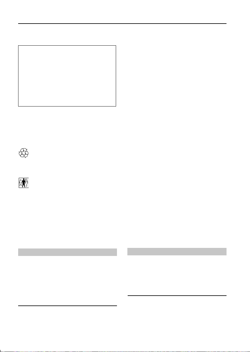
GEARBOX SELECTOR LEVER LABELS
A
H2608
Information concerning operation of the
transfer gearbox with either manual ‘A’ or
automatic gearbox ‘B’ is printed on the centre
console. This is important information and
must be understood fully with reference to the
‘Gearbox and Transmission’ sections of this
handbook, before using the transfer gearbox.
B
5
Page 7
Introduction
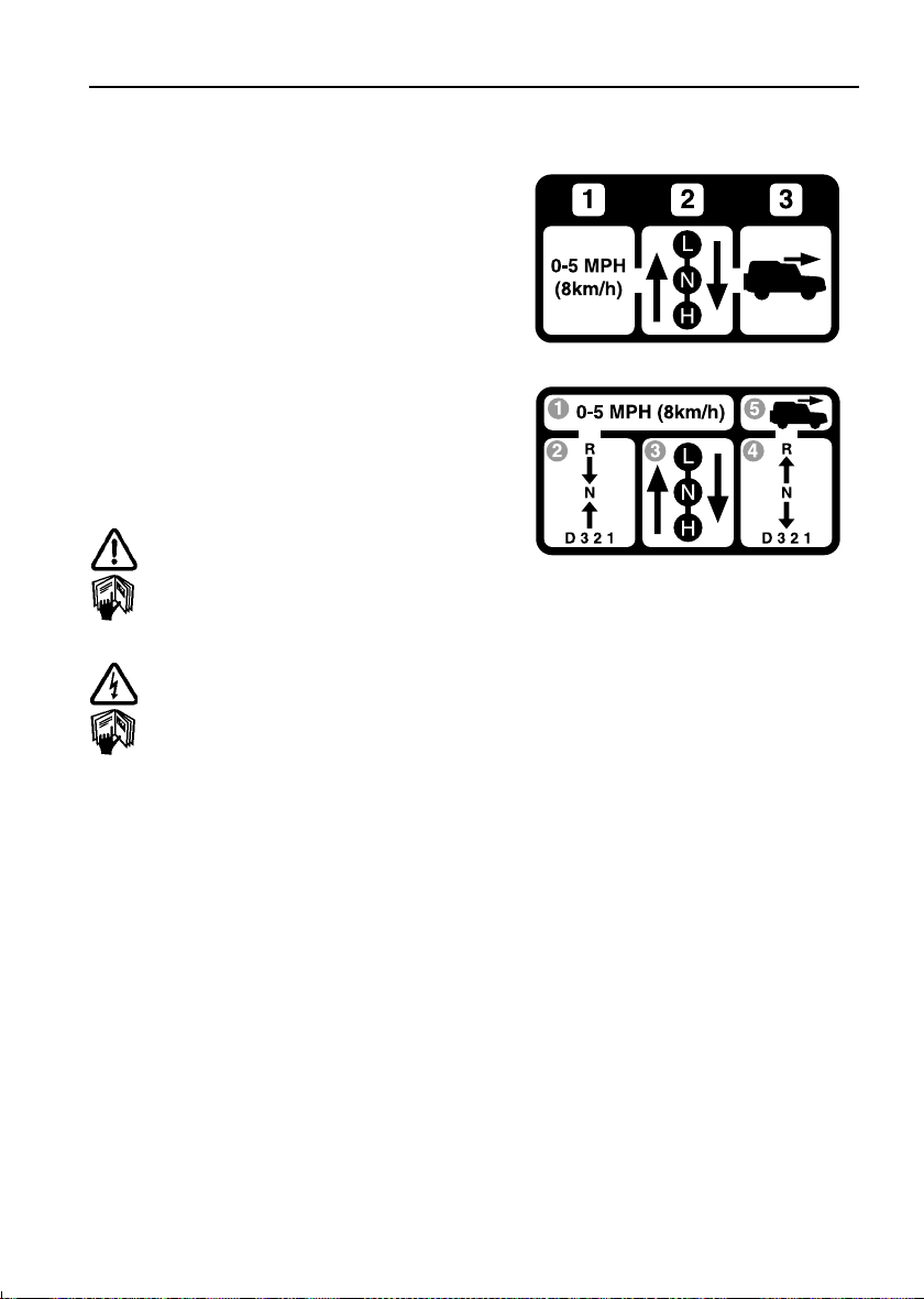
SUN VISOR LABELS
AIRBAG
SRS
1980
1940
2015
mm
mm
mm
78.0
79.5
76.5
INS
INS
INS
H2545
Always take careful note of warning information
about the airbag SRS attached to the sun visor
(illustrated above) or other parts of the vehicle.
Details of the vehicle's standard ride height,
both with and without an open sunroof are
printed on the drivers sun visor.
IN AN EMERGENCY
IMPORTANT INFORMATION
Remember the breakdown safety code
If a breakdown occurs while travelling:
• Wherever possible, consistent with
road safety and traffic conditions, the
vehicle should be moved off the main
thoroughfare, preferably into a lay-by. If
a breakdown occurs on a motorway,
pull well over to the inside of the hard
shoulder.
• Switch on hazard lights.
• If possible, position a warning triangle
or a flashing amber light at an
appropriate distance from the vehicle to
warn other traffic of the breakdown,
(note the legal requirements of some
countries).
• Consider evacuating passengers
through nearside doors onto the verge
as a precaution in case your vehicle is
accidentally struck by other traffic.
6
Page 8
Controls & Instruments
Controls
FASCIA. . . . . . . . . . . . . . . . . . . . . . . . . . . . . . . . . . 9
INSTRUMENT PANEL . . . . . . . . . . . . . . . . . . . . . 10
BINNACLE SWITCHES. . . . . . . . . . . . . . . . . . . . . 11
FASCIA SWITCHES . . . . . . . . . . . . . . . . . . . . . . . 12
Locks & Alarm
KEYS AND HANDSETS. . . . . . . . . . . . . . . . . . . . . 13
ALARM SYSTEM . . . . . . . . . . . . . . . . . . . . . . . . . 13
ENGINE IMMOBILISATION . . . . . . . . . . . . . . . . . 18
REMOTE HANDSET BATTERY . . . . . . . . . . . . . . . 20
CHILD-PROOF LOCKS . . . . . . . . . . . . . . . . . . . . . 21
DOOR LOCKING CUT-OFF SWITCH . . . . . . . . . . . 21
Seats
MANUALLY OPERATED FRONT SEATS. . . . . . . . 22
POWER OPERATED FRONT SEATS . . . . . . . . . . . 23
HEAD RESTRAINTS. . . . . . . . . . . . . . . . . . . . . . . 26
FOLDING ARMRESTS . . . . . . . . . . . . . . . . . . . . . 26
HEATED FRONT SEATS . . . . . . . . . . . . . . . . . . . . 27
FOLDING THE REAR SEATS. . . . . . . . . . . . . . . . . 27
OCCASIONAL REAR SEATS. . . . . . . . . . . . . . . . . 29
Seat Belts
SEAT BELT SAFETY . . . . . . . . . . . . . . . . . . . . . . . 32
SEAT BELTS. . . . . . . . . . . . . . . . . . . . . . . . . . . . . 33
SEAT BELT PRE-TENSIONERS . . . . . . . . . . . . . . 34
CARING FOR SEAT BELTS. . . . . . . . . . . . . . . . . . 34
Child Restraints
CHILD SEATS. . . . . . . . . . . . . . . . . . . . . . . . . . . . 35
ISOFIX CHILD RESTRAINTS . . . . . . . . . . . . . . . . 36
7
Page 9

Airbag SRS
AIRBAG SRS. . . . . . . . . . . . . . . . . . . . . . . . . . . . 38
HOW THE AIRBAG SRS WORKS. . . . . . . . . . . . . 39
SERVICE INFORMATION. . . . . . . . . . . . . . . . . . . 41
Air Conditioning
VENTILATION . . . . . . . . . . . . . . . . . . . . . . . . . . . 69
AIR CONDITIONING CONTROLS. . . . . . . . . . . . . 70
GENERAL NOTES . . . . . . . . . . . . . . . . . . . . . . . . 73
Steering Column
STEERING COLUMN ADJUSTMENT . . . . . . . . . . 42
Door Mirrors
EXTERIOR MIRRORS . . . . . . . . . . . . . . . . . . . . . 43
Instruments
INSTRUMENT PANEL . . . . . . . . . . . . . . . . . . . . . 45
Warning Lights
INSTRUMENT PANEL . . . . . . . . . . . . . . . . . . . . . 47
Audible Warnings
AUDIBLE WARNINGS . . . . . . . . . . . . . . . . . . . . . 52
Lights & Indicators
DIRECTION INDICATORS . . . . . . . . . . . . . . . . . . 53
LIGHTS . . . . . . . . . . . . . . . . . . . . . . . . . . . . . . . . 53
FOG LIGHTS . . . . . . . . . . . . . . . . . . . . . . . . . . . . 55
HAZARD WARNING LIGHTS. . . . . . . . . . . . . . . . 56
Wipers & Washers
OPERATING . . . . . . . . . . . . . . . . . . . . . . . . . . . . 57
WINDSCREEN WIPERS . . . . . . . . . . . . . . . . . . . 57
WINDSCREEN WASHER. . . . . . . . . . . . . . . . . . . 58
HEADLIGHT WASHERS . . . . . . . . . . . . . . . . . . . 58
REAR WINDOW WIPER AND WASHER . . . . . . . 59
Horn
HORN . . . . . . . . . . . . . . . . . . . . . . . . . . . . . . . . . 60
Electric Windows
ELECTRIC WINDOWS. . . . . . . . . . . . . . . . . . . . . 61
Heated Screens
HEATED FRONT SCREEN AND REAR WINDOW . 74
Interior Equipment
FRONT INTERIOR & LOADSPACE LIGHTS . . . . . 75
REAR INTERIOR LIGHTS . . . . . . . . . . . . . . . . . . 75
GLOVEBOX LIGHT . . . . . . . . . . . . . . . . . . . . . . . 75
CLOCK . . . . . . . . . . . . . . . . . . . . . . . . . . . . . . . . 76
COIN TRAY . . . . . . . . . . . . . . . . . . . . . . . . . . . . . 76
CIGAR LIGHTER . . . . . . . . . . . . . . . . . . . . . . . . . 77
ASHTRAYS . . . . . . . . . . . . . . . . . . . . . . . . . . . . . 77
UNDER SEAT STOWAGE BOX. . . . . . . . . . . . . . . 78
AUXILIARY POWER SOCKET . . . . . . . . . . . . . . . 79
CUP HOLDERS . . . . . . . . . . . . . . . . . . . . . . . . . . 79
CUBBY BOX . . . . . . . . . . . . . . . . . . . . . . . . . . . . 80
SUN VISOR VANITY MIRROR ILLUMINATION . . 80
INTERIOR REAR-VIEW MIRROR . . . . . . . . . . . . 81
Rear Step
REAR STEP. . . . . . . . . . . . . . . . . . . . . . . . . . . . . 82
Loadspace Cover
LOADSPACE COVER . . . . . . . . . . . . . . . . . . . . . . 83
In-Car Telephones
IN-CAR TELEPHONES. . . . . . . . . . . . . . . . . . . . . 84
In-Car Entertainment
RADIO AERIAL . . . . . . . . . . . . . . . . . . . . . . . . . . 85
IN-CAR ENTERTAINMENT . . . . . . . . . . . . . . . . . 85
HEADPHONE CONTROLS . . . . . . . . . . . . . . . . . . 85
RADIO REMOTE CONTROLS. . . . . . . . . . . . . . . . 86
Sunroof
MANUAL SUNROOF . . . . . . . . . . . . . . . . . . . . . . 62
ELECTRIC SUNROOF . . . . . . . . . . . . . . . . . . . . . 63
Heating & Ventilation
VENTILATION . . . . . . . . . . . . . . . . . . . . . . . . . . . 65
HEATER CONTROLS. . . . . . . . . . . . . . . . . . . . . . 66
USING YOUR HEATER . . . . . . . . . . . . . . . . . . . . 67
8
Page 10
Controls & Instrum ents
Controls
FASCIA
Controls
23 745 61
8
9
16
1213141517
11
10
H3565
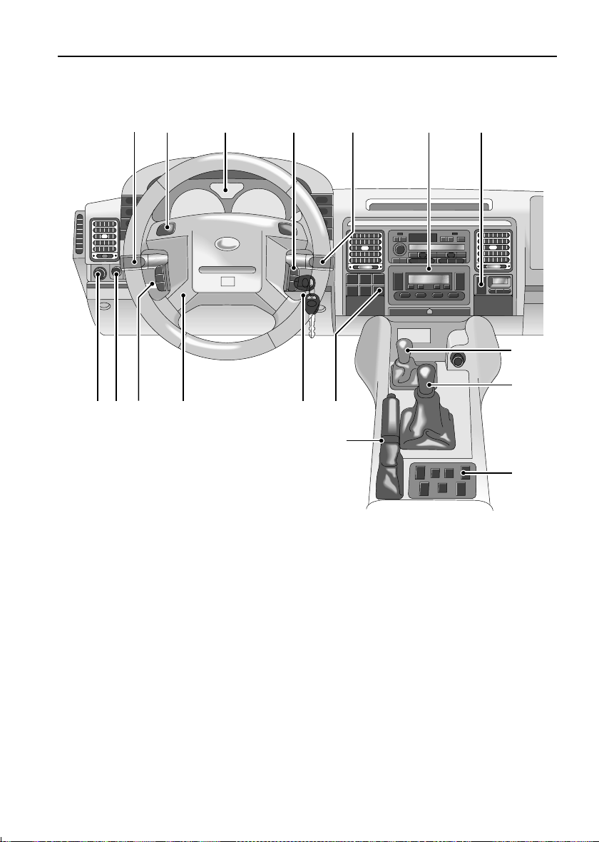
1. Lighting and direction indicator controls
2. Horn switches
3. Instrument panel
4. Cruise control switches
5. Windscreen wiper/washer controls
6. Heater/air conditioning controls
7. Door locking switch
8. Transfer gear lever
9. Main gear lever
NOTE: The precise specification and location of the controls may vary according to territorial
requirements and from model to model within the vehicle range.
*
10. Electric window switches
11. Handbrake
12. Fascia panel switches
13. Starter switch
14. Steering column height adjuster
15. Remote radio controls
16. Headlamp levelling control*
17. Electric mirror adjuster
9
*
Page 11
INSTRUMENT PANEL
km
Controls
2
3
53
00
km
45 61
H2618a
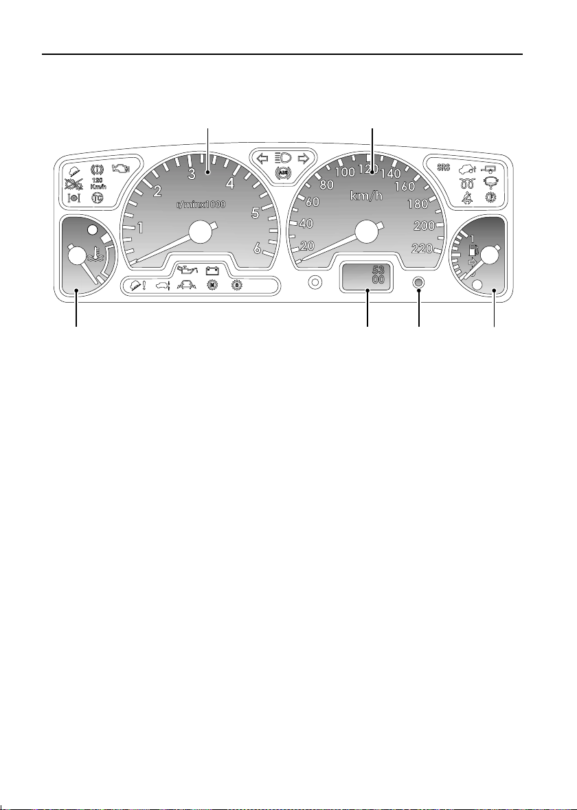
1. Temperature gauge
Under normal operating conditions the
pointer will rise to a position within the
white segment.
2. Tachometer
Indicates engine speed in revolutions per
minute (x 1000)
3. Speedometer
Indicates road speed in miles per hour
and/or kilometers per hour.
NOTE: This is a brief overview of the instrument panel, for a more detailed description of each
instrument please refer to ‘INSTRUMENT PANEL’, page 45.
4. Total distance (odometer) and trip
recorder
NOTE: On automatic gearbox vehicles the
display also indicates the selector lever
position
5. Trip recorder reset button
6. Fuel gauge
The pointer drops to zero when the starter
switch is turned off, but quickly rises to
show the level of fuel in the tank when the
switch is turned to position ‘II’.
10
Page 12
BINNACLE SWITCHES
53
00
km
H2636a
Controls
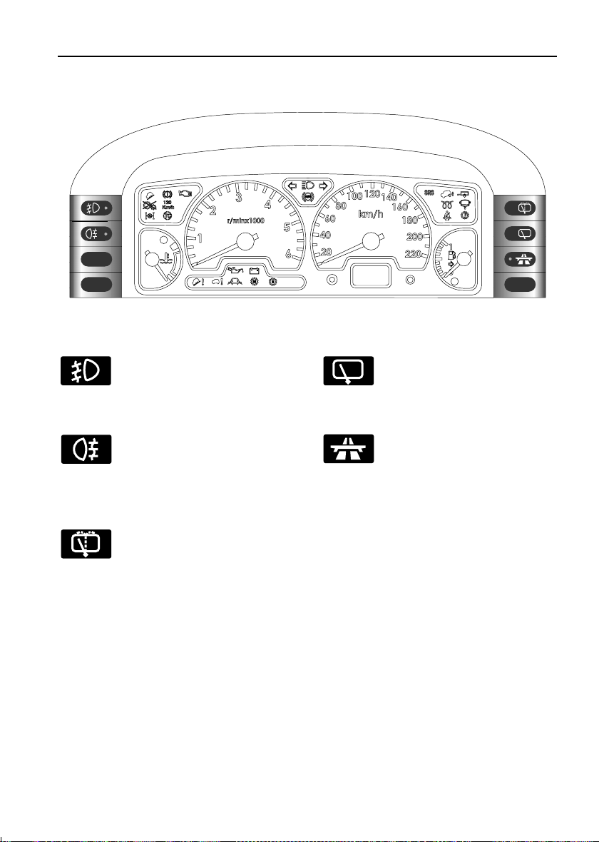
Front fog lights*
Operation and function of the front
fog lights are described under
‘Front fog lights*’, page 55.
Rear fog guard lights
Operation and function of the rear
fog guard lights are described
under ‘Rear fog guard lights’,
page 55.
Rear window wash/wipe
The functions of the wash/wipe
switch are described under ‘Rear
window wash/wipe’, page 59.
Rear window wiper
The functions of the rear window
wiper switch are described under
‘Rear window wiper’, page 59.
Cruise control
Operation and functions of the
cruise control switch are described
under ‘CRUISE CONTROL*’,
page 106.
11
Page 13
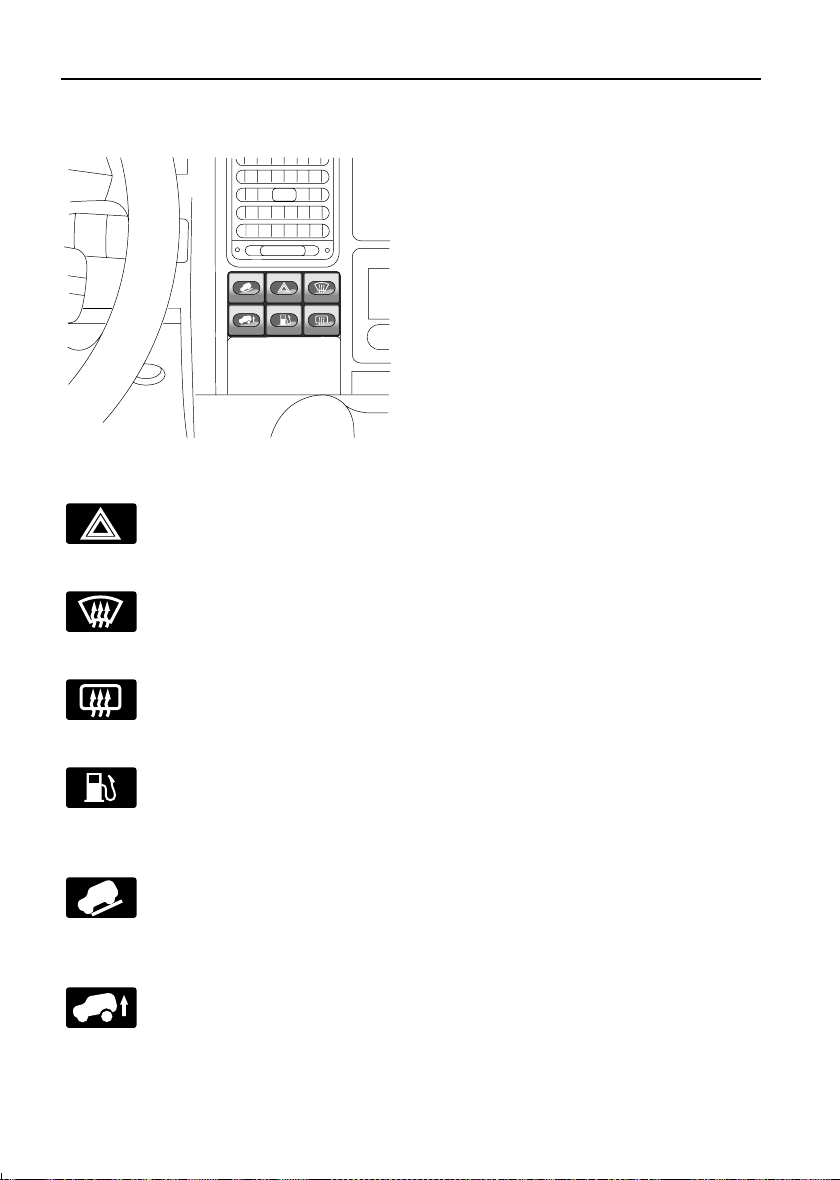
FASCIA SWITCHES
H2637
Hazard warning lights
Press to operate (see ‘HAZARD
WARNING LIGHTS’, page 56).
Controls
Heated front screen
Heated rear window
Fuel filler flap
Hill descent control (HDC)
Off-road suspension mode
suspension’).
*
Press to operate (see ‘Heated front
screen*’, page 74).
Press to operate (see‘Heated rear
window’, page 74).
With the starter switch turned to
position ‘0’ or ‘1’, press to open the
fuel filler flap.
Press to select hill descent control
(see ‘HILL DESCENT CONTROL’,
page 112).
Press to raise or lower the
suspension to or from off-road
height (see ‘Self-levelling
*
12
Page 14
Locks & Alarm
Locks & Alarm
KEYS AND HANDSETS
You have been supplied with two remote
handsets with integral keys which operate all
locks.
The key number is stamped on a tag attached to
the key ring. Check that the key number has
been entered in the space provided on your
Security card.
If the remote handset is lost, contact a Land
Rover dealer, who can supply replacement
units.
WARNING
Keep the Security card and spare handset in a
safe place - NOT IN THE VEHICLE!
ALARM SYSTEM
Your vehicle is fitted with a sophisticated
electronic anti-theft alarm and engine
immobilisation system. There are also a
number of additional security features, some of
which are selectable options and some are
standard features of the vehicle. In order to
ensure maximum security and operating
convenience, you are strongly advised to gain a
full understanding of the features and
alternatives available, by thoroughly reading
this section of the handbook.
IMPORTANT INFORMATION
FOR MAXIMUM SECURITY ALWAYS
SUPERLOCK THE VEHICLE USING THE
REMOTE HANDSET (except when
passengers are to be left inside or if it is
necessary to leave a window or sunroof
open).
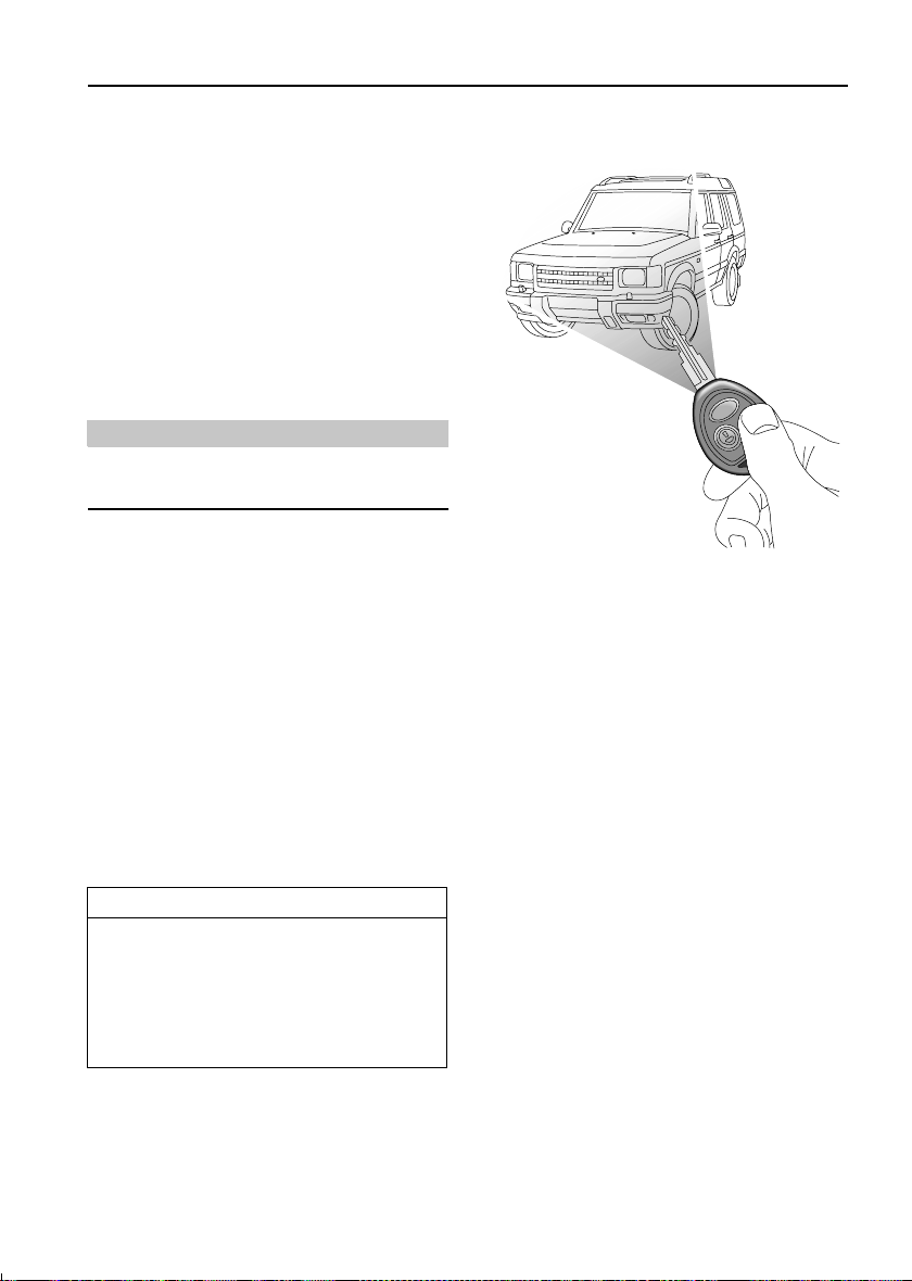
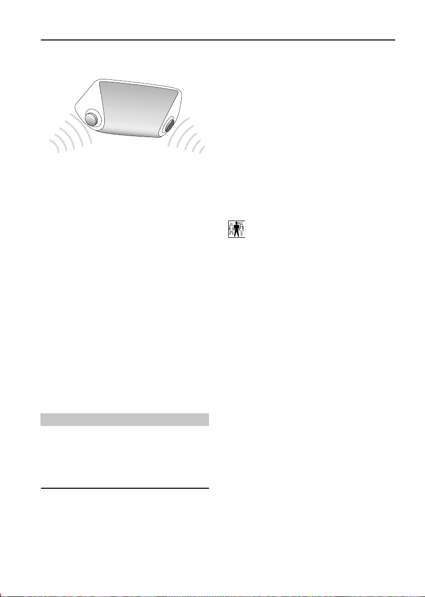
Using the remote handset
H2467
While it is not necessary to point the handset at
the vehicle, the handset must be within range of
the vehicle when a button is pressed. Note that
the operating range may vary depending upon
handset battery condition and may sometimes
be limited by physical and geographical factors
beyond your control. From a security point of
view, it may not be wise to unlock unless you
are within a few feet of the vehicle.
Locking
With the remote handset:
Press the lock (padlock symbol) button once:
• all doors are superlocked (see
‘Superlocking’, page 14)
• engine immobilised
• perimetric alarm activated (protects the
doors, bonnet and taildoor)
• interior space protection activated
The direction indicator lights flash three times
to confirm that the vehicle is secure and the
anti-theft alarm indicator light (in the
instrument panel) starts to flash.
13
Page 15

Locks & Alarm
With the key:
Insert the key and turn the door lock towards
the rear of the vehicle:
• all doors locked (not superlocked)
• engine immobilised
• perimetric alarm activated (protects the
doors, bonnet and taildoor)
• NO INTERIOR SPACE PROTECTION
The direction indicator lights flash once to
confirm that the vehicle is secure and the
anti-theft alarm indicator light (in the
instrument panel) starts to flash.
Unlocking
With the remote handset:
• Press the unlock (Land Rover) button once
to disarm the alarm and unlock the driver's
door only (see ‘Single point entry’,
page 16).
• Press the unlock button twice to disarm the
alarm and unlock ALL the doors.
In either case, the direction indicator lights
flash once and the interior lights illuminate.
With the key:
While the doors can be unlocked using the key,
this method is NOT RECOMMENDED depending on the specification of the vehicle
the alarm may not be disarmed.
Superlocking
Provided all the doors are fully closed, the
Superlocking feature is activated automatically
whenever the vehicle is locked using the remote
handset. Superlocking immobilises the interior
door handles, thereby preventing an intruder
from gaining entry by smashing a window and
reaching inside the vehicle to operate the door
handles.
Note that locking with the key will not activate
superlocking.
WARNING
For safety, NEVER use Superlocking if
passengers are to remain inside the vehicle in an emergency they would not be able to
escape.
NOTE: If the handset does not operate after the
vehicle has been parked for a long period,
unlock the driver's door with the key and then
try again. If the handset still fails to operate,
enter the EKA code using the procedure shown
later in this section.
14
Page 16
Locks & Alarm
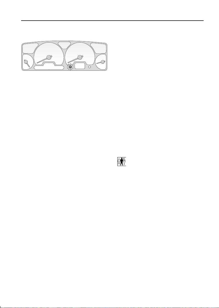
Anti-theft alarm indicator light
H2546
This light provides information about the status
of the alarm system, as follows:
When the vehicle is locked:
The light flashes rapidly while the alarm is
arming itself. After ten seconds, the light
adjusts to a slower frequency and continues to
flash as an anti-theft deterrent until the alarm is
disarmed.
If the engine is immobilised (even though the
alarm has been disarmed):
The light flashes slowly until the engine is
remobilised.
If the alarm has been triggered:
The light will flash rapidly when the alarm is
disarmed until the starter switch is turned to
position II.
If the remote handset battery power is low:
The light will flash rapidly for ten seconds after
the handset has been used when the driver's
door is opened.
Mislock
If the driver's door is not fully closed when the
handset lock button is pressed, the alarm
sounder or vehicle horn will sound once,
indicating a mislock. In this case, none of the
doors will lock and the alarm system will not be
armed.
If a passenger door or other aperture is not fully
closed when the handset lock button is
pressed, the alarm sounder or vehicle horn will
sound once, indicating a mislock. However, the
‘partial arming’ attributes of the security system
will enable as much of the system to be armed
as possible (all fully closed door or bonnet
apertures will be protected, but an open door
will not!). As soon as the open aperture is
closed, the system will automatically revert to a
fully armed state.
NOTE: If a mislock occurs as a result of an open
door, the superlocking and interior space
protection features will not be activated.
The mislock audible warning can be
disabled by a Land Rover dealer.
If the alarm sounds
If the alarm is triggered, the alarm sounder or
vehicle horn will sound for 30 seconds before
switching off and resetting itself to the same
protection status that existed prior to the alarm
being triggered.
To silence the alarm, press either button on the
remote handset.
15
Page 17
Locks & Alarm
Headlight courtesy delay
When locking the vehicle, the remote handset
can be used to illuminate the headlights for 30
seconds. At night this will make it easier for you
to unlock the garage, or walk to your house in
safety. Operate this feature at the same time as
you lock the car, by keeping the handset LOCK
button pressed for more than 2 seconds (the
doors lock and alarm system arms in the usual
way).
To extinguish the lights before the 30 second
illumination period has expired, press the lock
button again.
The headlight courtesy delay can be
disabled by a Land Rover dealer.
Single point entry
This is a personal security feature, which
enables the driver's door only to be unlocked,
leaving the other doors in a locked state. It can
be operated by the remote handset as follows:
• press the unlock button once to unlock the
driver's door.
• press a second time (within one minute) to
unlock the remaining doors.
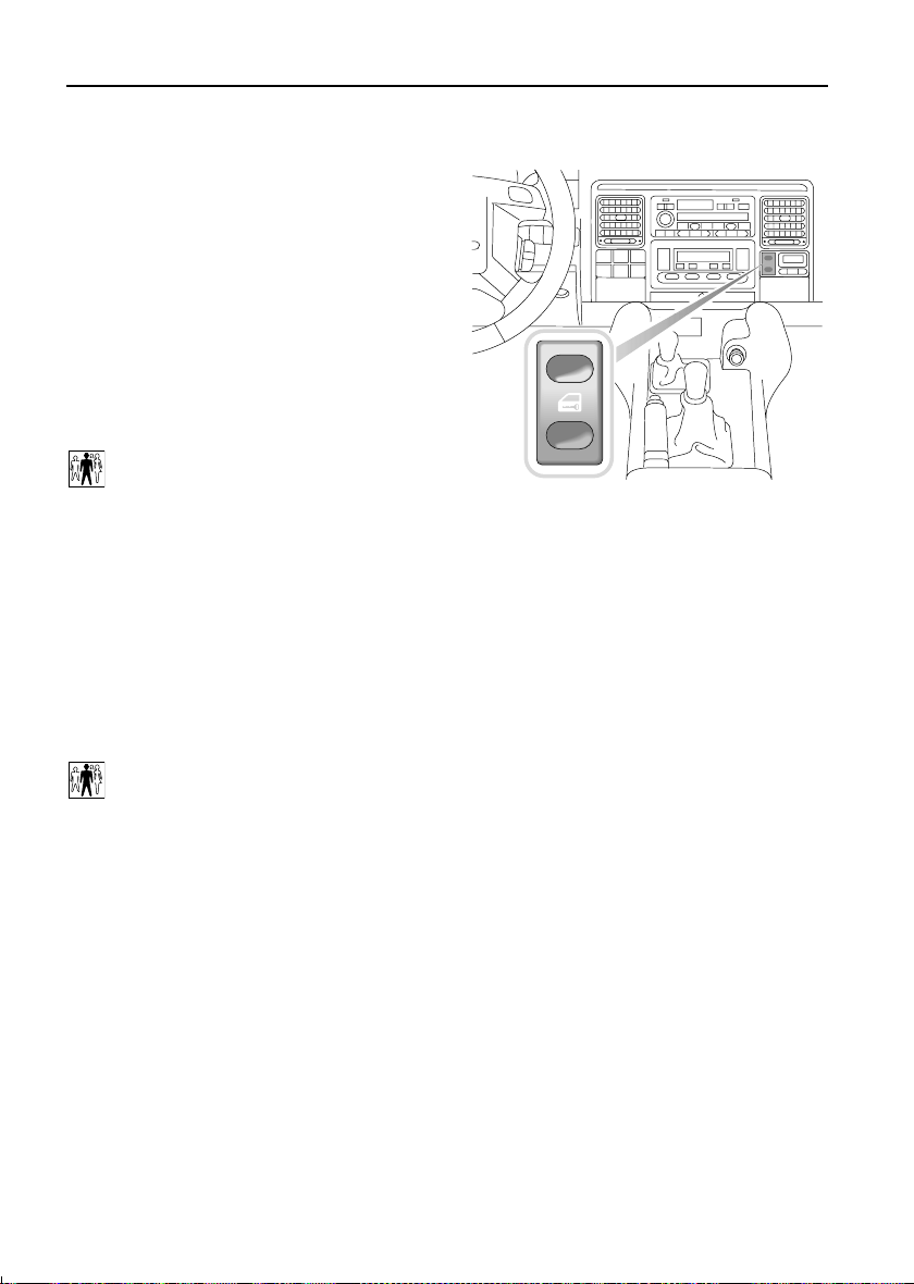
Interior locking switch
H2633
This is a personal security feature which allows
the driver to lock (or unlock) all the doors from
inside the vehicle (while driving or with the
vehicle stationary). Press the lower part of the
switch to lock (the alarm will not be armed),
and the upper part to unlock.
NOTE: If the locks have already been
superlocked, the switch will not release the
locks.
Single point entry can be disabled by a
Land Rover dealer.
Interior door handles and door sill locking
buttons
From inside the vehicle, each door can be
individually locked by depressing the
appropriate door sill button. However, doors
cannot be unlocked by raising the sill button.
Use the door handles to unlock, as follows:
• First operation of the door handle unlocks
the door.
• Second operation of the door handle opens
the door.
16
Page 18
Locks & Alarm
Interior space protection
H2468
Interior space protection is designed to protect
the interior of the vehicle from intrusion (entry
by a thief through a smashed window, for
example). Two pairs of sensors monitor the
interior space and activate the alarm if air
movement is detected in the passenger
compartment.
Using the handset:
Interior space protection is activated
automatically whenever the remote handset is
used to set the alarm and can ONLY be
deactivated with the handset.
Key operation:
Using the key will NOT activate (or deactivate)
interior space protection.
Speed-related locking
This security feature locks all the doors
automatically when the vehicle speed exceeds
7 km/h, and unlocks the doors as soon as the
starter switch is turned off (provided the doors
had previously been locked by the
speed related feature).
Note speed-related locking is not selectable by
the driver, and that operation of the door locks
by any other means (interior locking switch on
the fascia panel, for example) will disable the
speed-related locking function for the
remainder of the journey, or until the starter
switch is turned off and on again.
Speed related locking can be selected or
deselected by a Land Rover dealer.
*
NOTE: Interior space protection cannot be
activated if a door is open, or if the starter
switch is turned on.
WARNING
Never activate interior space protection if
windows or sunroof are to be left open, or if
passengers or animals are to be left inside
the vehicle - any movement will activate the
alarm.
17
Page 19
Locks & Alarm
ENGINE IMMOBILISATION
Engine immobilisation is an important aspect of
the security system, and includes a feature
known as ‘passive immobilisation’. This is
designed to safeguard the vehicle from theft,
should the driver forget to lock the doors and
prevents the engine from being started unless
the GENUINE handset key is inserted into the
starter switch. Engine immobilisation is
automatic whenever any of the following
conditions occur.
• The vehicle is locked using handset or key.
• Thirty seconds after the starter switch has
been turned off AND the driver's door
opened.
• Five minutes after the starter switch is
turned off, or the alarm system is disarmed.
IMPORTANT INFORMATION
When entering a code:
• ENSURE each key movement is carried
out with care and precision and turned
to the full extent of its travel.
• After turning the key to either the lock
or unlock positions, make sure it is
FULLY returned to the centre (vertical)
position.
• An interval of 10 seconds or more
between key turns, or the key being
held in a locked or unlocked position
for 5 seconds or more will cancel an
entry attempt, in which case you must
start again with operation 1.
NOTE: The engine will be re-mobilised
automatically whenever the genuine handset
key is inserted into the starter switch and
turned to position ‘II’.
Emergency key access
If the handset is damaged, or fails to operate,
the engine can be re-mobilised by using the key
to enter a unique four number emergency key
access code. The code is recorded on the
Security Information card and is entered as
follows:
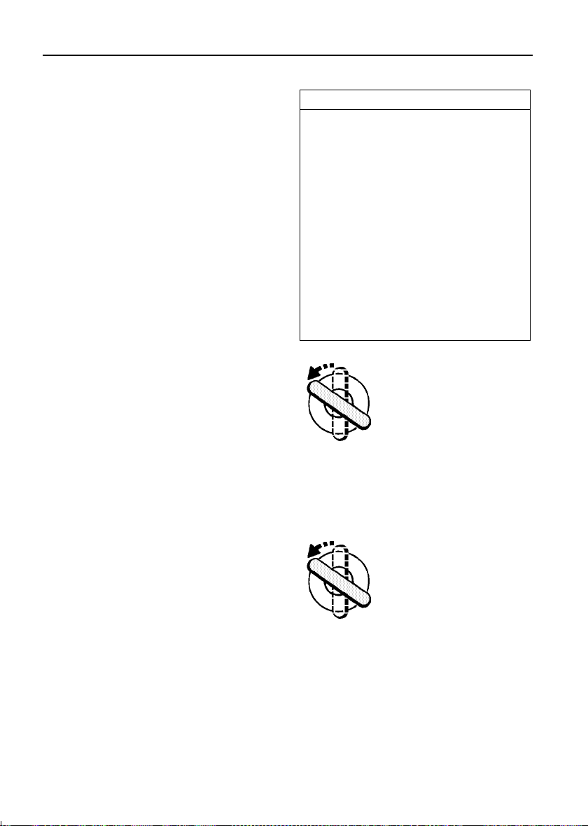
1. Ensure that all doors are
closed, then using the key turn
the driver's door lock to the
UNLOCK position (towards the
front of the car) and hold in
this position for at least 5
seconds until the alarm sounder sounds once).
Then return the key to the centre position. It is
now possible to use the key to enter the
separate numerical values of the four numbers
that make up the emergency key access code.
2. Enter the FIRST number of
the code. If the first number is
4, turn the key (towards the
front of the car) to the UNLOCK
position 4 times. Ensure the
key is FULLY returned to the
centre position after each turn.
18
Page 20
Locks & Alarm
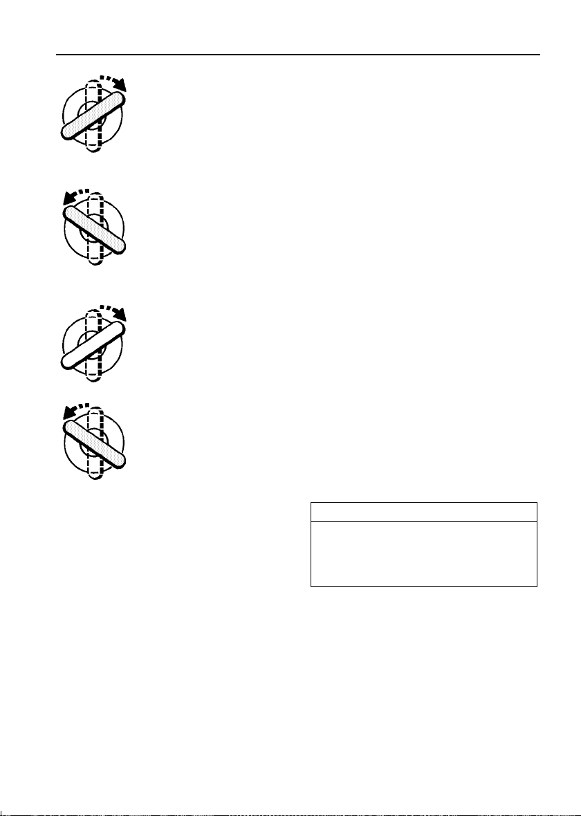
3. Enter the SECOND number
of the code. If the second
number is 3, turn the key
(towards the rear) to the LOCK
position 3 times. Remember;
the key must be FULLY
returned to the centre position after each turn.
4. Enter the THIRD number of
the code. If the third number is
12, turn the key to the UNLOCK
position twelve times,
ensuring that the key is FULLY
returned to the centre position
after each turn.
5. Enter the FOURTH number
of the code. If the fourth
number is 1, turn the key to the
LOCK position once. Ensure
the key is FULLY returned to
the centre position.
6. Finally, turn the key to the
unlock position once more. If
the code has been entered
correctly, a double ‘bleep’ will
sound (a single ‘bleep’
indicates that the code has
been entered incorrectly).
NOTE: If the Mislock audible warning has been
deselected (by a Land Rover dealer), the alarm
sounder will not sound when an EKA code has
been entered. Instead, the alarm indicator light
on the instrument panel will flash once (for one
second) to indicate a successful code entry.
7. Through the driver's door window, observe
the anti-theft alarm indicator light on the
instrument panel. If code entry was successful,
this light will continue flashing (once every two
seconds) for the five minute delay period.
DO NOT OPEN THE DOOR OR ATTEMPT TO
ENTER THE VEHICLE until the full delay period
has elapsed - this will be indicated by the
anti-theft alarm indicator light extinguishing.
8. Now open the door, insert the key into the
starter and turn the switch to position ‘II’
IMMEDIATELY! If the starter switch is not
turned to position ‘II’ within 30 seconds of the
indicator light extinguishing, the engine will
automatically immobilise again.
If an incorrect code has been entered:
If an incorrect code has been entered, the alarm
sounder will sound once and the anti-theft
alarm indicator light will continue to flash. In
this case, return to operation ‘1’ and re-enter
the code.
After three failed entry attempts, the security
system invokes a delay period of ten minutes
during which the system will not accept any
further attempts to enter a code.
IMPORTANT INFORMATION
Memorise the emergency key access code
or keep the Security card on your person in
case of emergencies. NEVER leave the card
in the vehicle.
There is now a five minute delay before the
alarm and engine immobiliser are deactivated.
DO NOT OPEN THE DOOR OR ATTEMPT TO
ENTER THE VEHICLE YET!
19
Page 21
Locks & Alarm
REMOTE HANDSET BATTERY
The battery should last for approximately
three years dependent upon use. When the
battery needs replacing it will be apparent from
the following symptoms:
• A gradual deterioration in range and
performance.
• The alarm indicator light in the instrument
panel will flash rapidly for 10 seconds after
the driver's door is opened.
Always fit a Land Rover STC 4080 or a
Panasonic CR2032 replacement battery
(available from a Land Rover dealer).
WARNING
The handset contains delicate electronic
circuits and must be protected from impact
and water damage, high temperatures and
humidity, direct sunlight and the effects of
solvents, waxes and abrasive cleaners.
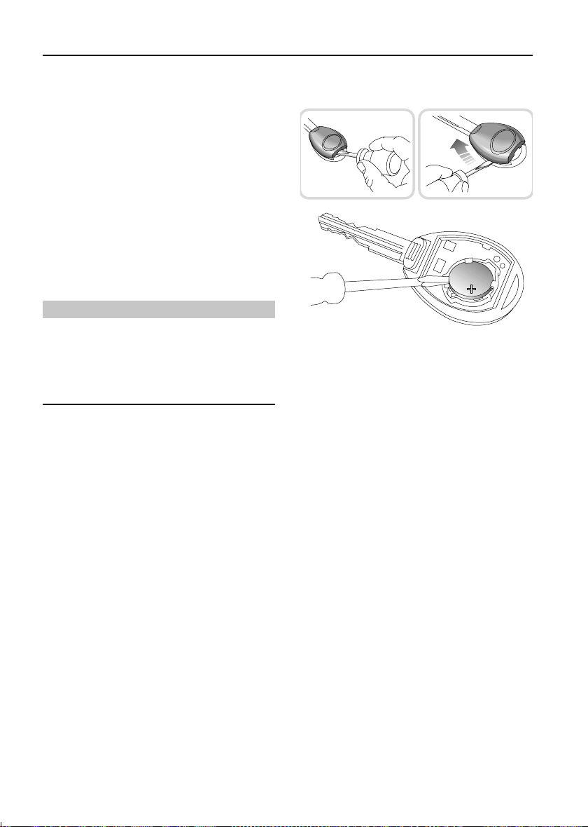
Battery replacement
H2794
1. With the handset face down, insert the
blade of a small flat-bladed screwdriver
into the slot at the rear of the handset (see
inset) and prise the back upwards.
2. Insert the screwdriver blade as shown in
the right hand inset and then carefully
slide it along the joint towards the key to
release the back of the handset.
3. Use a small flat-bladed screwdriver to
prise the battery from its mounting (see
illustration), taking care to avoid touching
the circuit board or the metal battery
contacts.
4. Fit the new battery, ensuring that correct
polarity is maintained (‘+’ side facing up).
Finger marks will adversely affect battery
life; if possible, avoid touching the flat
surfaces of the battery and wipe them
clean before fitting.
5. Press the two halves of the handset firmly
together and ensure that both halves are
fully joined to prevent dirt or moisture
from entering the handset.
The handset is now ready for use.
20
Page 22
Locks & Alarm
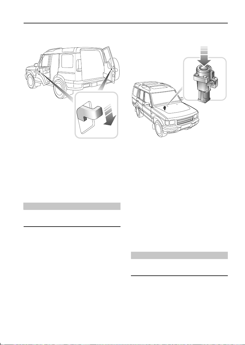
CHILD-PROOF LOCKS
H2464
Move the locking levers on the rear doors and
taildoor down to engage the child locks.
With the child-proof locks engaged, neither the
rear doors nor the taildoor can be opened from
inside the vehicle, thereby avoiding the risk of a
door being opened accidentally while the
vehicle is moving.
WARNING
NEVER leave children unsupervised in the
vehicle.
DOOR LOCKING CUT-OFF SWITCH
H2574
An inertia switch, operational only with the
starter switch in position ‘II’ and the alarm
disarmed, prevents the doors centrally locking
(or if the doors are locked, will unlock them) in
the event of an accident or sudden impact.
When the switch operates, the direction
indicator lights flash (if market permits), until
the system is reset by turning the starter switch
on and off, and opening and closing the driver's
door.
Note that doors cannot be locked again until the
switch is reset.
The inertia switch also cuts off the fuel supply
(see ‘FUEL CUT-OFF SWITCH’, page 99).
WARNING
Always check for fuel leaks before resetting
the switch!
21
Page 23
Seats
Seats
MANUALLY OPERATED FRONT SEATS
WARNING
To avoid the risk of loss of control and
personal injury, DO NOT adjust the driver's
seat while the vehicle is in motion.
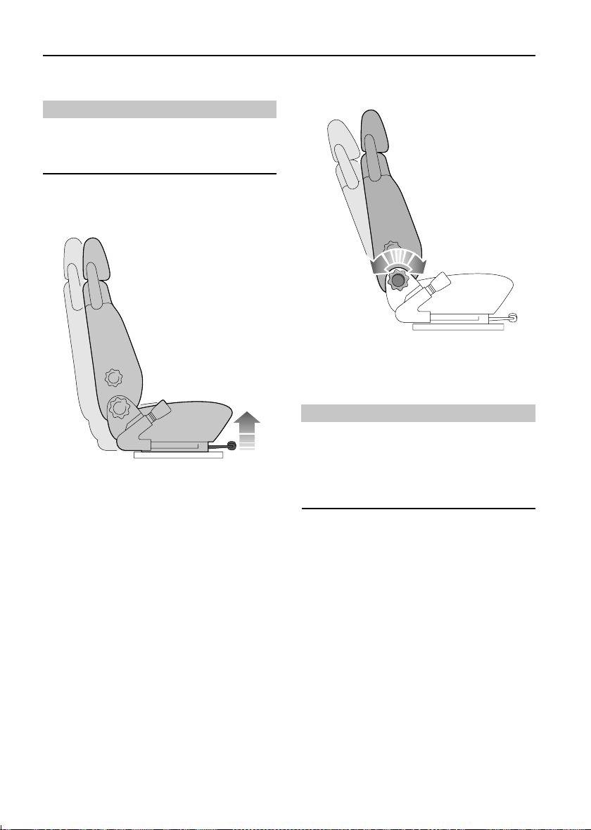
Forward/backward adjustment
H2620
Lift the lever to slide the seat forward or back.
Ensure the seat is locked in position before
driving.
Seat back adjustment
H2621
Rotate the handwheel to achieve the desired
backrest angle.
WARNING
DO NOT travel with the seat backs reclined
steeply rearwards. Optimum benefit is
obtained from the seat belt with the seat back
angle set to approximately 25 degrees from
the upright (vertical).
22
Page 24
Seats
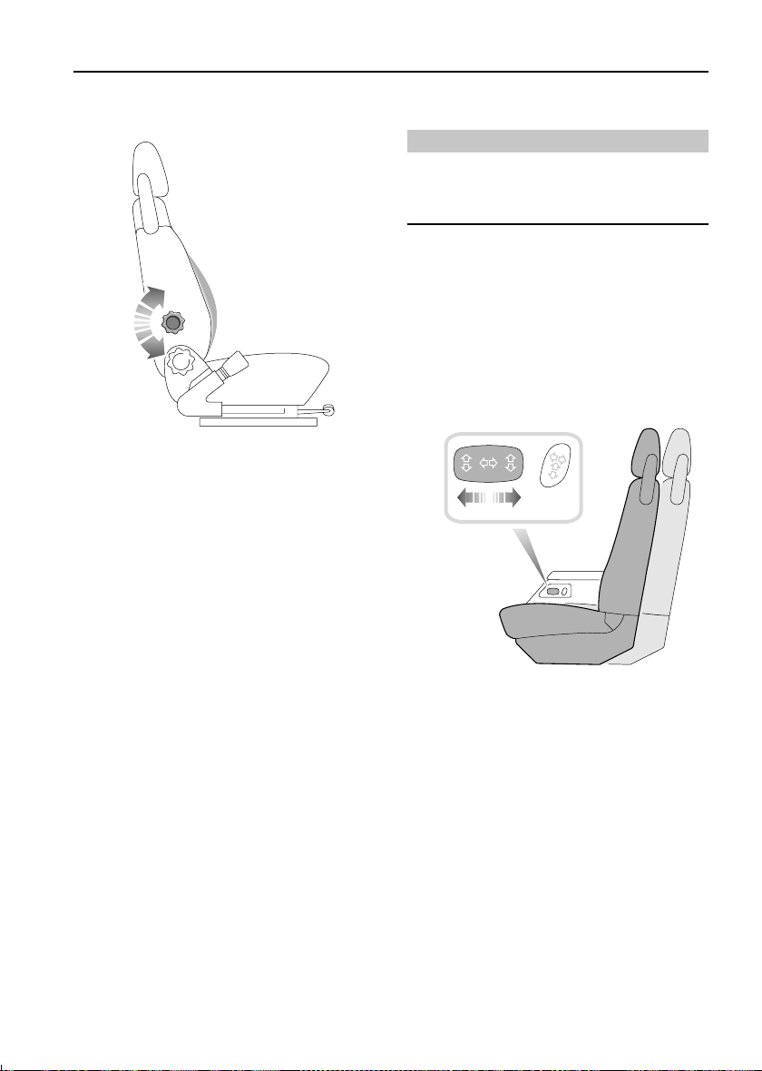
Lumbar support adjustment
H2622
Rotate the handwheel to increase or decrease
support to the lumbar region of the back.
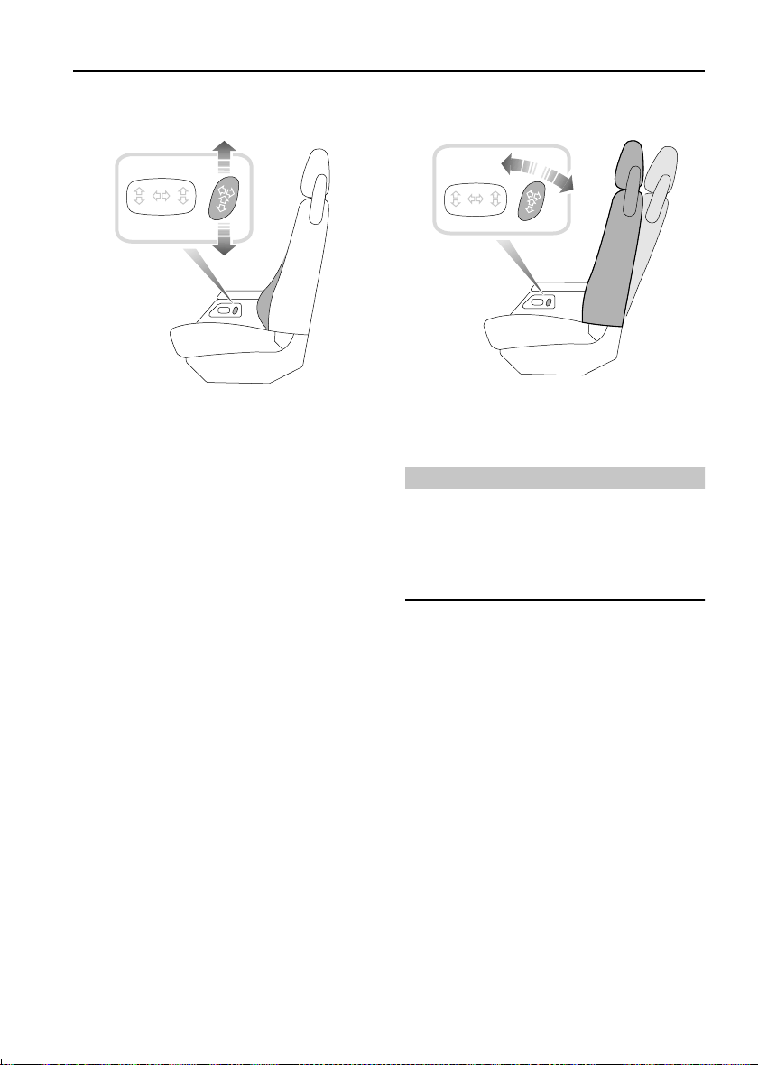
POWER OPERATED FRONT SEATS*
WARNING
To avoid the risk of loss of control and
personal injury, DO NOT adjust the driver's
seat while the vehicle is in motion.
The seat adjustment controls are situated on
the side of the centrally mounted cubby box.
Seat adjustment is only possible when the
starter switch is turned to position ‘II’ or for 45
seconds after opening the driver's door.
Forward/backward adjustment
H2623
Push and hold the switch forwards or
backwards to move the seat to the desired
position.
23
Page 25
Seats
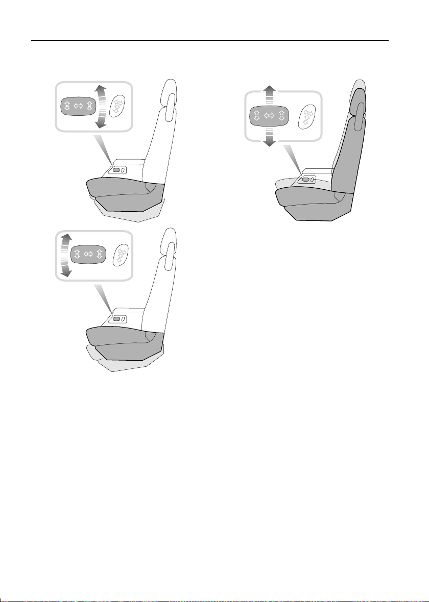
Seat cushion angle adjustment
Seat cushion height adjustment
H2625
On the driver's seat only, the height of the seat
cushion can be adjusted. Push the switch up or
down to raise or lower the cushion.
H2624
Twist the switch to tilt the seat cushion to the
desired position. Note that the front and rear of
the switch work independently - the front
raising or lowering the front of the cushion, the
rear of the switch similarly controlling the rear
of the seat cushion.
24
Page 26
Seats
Lumbar support adjustment
H2626
Push the switch up to increase support to the
lumbar region of the back. Lower the switch to
reduce lumbar support.
Seat back adjustment
H2627
Twist the switch forward or backward until the
desired seat back angle is achieved.
WARNING
DO NOT travel with the seat backs reclined
steeply rearwards. Optimum benefit is
obtained from the seat belt with the seat back
angle set to approximately 25 degrees from
the upright (vertical).
25
Page 27
Seats
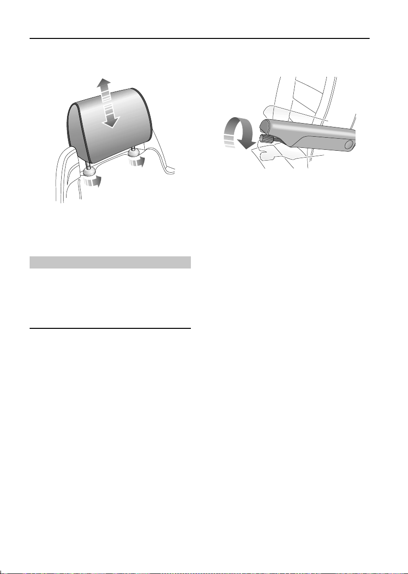
HEAD RESTRAINTS
H2465
Pull the head restraint up or down until the
cushion is level with the back of the head.
WARNING
Head restraints are designed to support the
back of the head (NOT THE NECK), and to
restrain rearward movement of the head in
the event of a collision. The restraint must be
positioned level with the head to be effective.
FOLDING ARMRESTS*
H2553
Some vehicles are fitted with adjustable front
seat armrests, which can be either; stowed
vertically in line with the seat backrest when not
required, or folded horizontally to serve as an
arm/elbow rest.
The height/angle of each armrest can be
adjusted by turning the knob set into the end of
the armrest: clockwise to raise and
anti-clockwise to lower.
Head restraint removal
Turn both mounting collars fully anti-clockwise
and pull the restraint upwards to remove.
After replacing a head restraint turn the
mounting collars clockwise.
26
Page 28
Seats
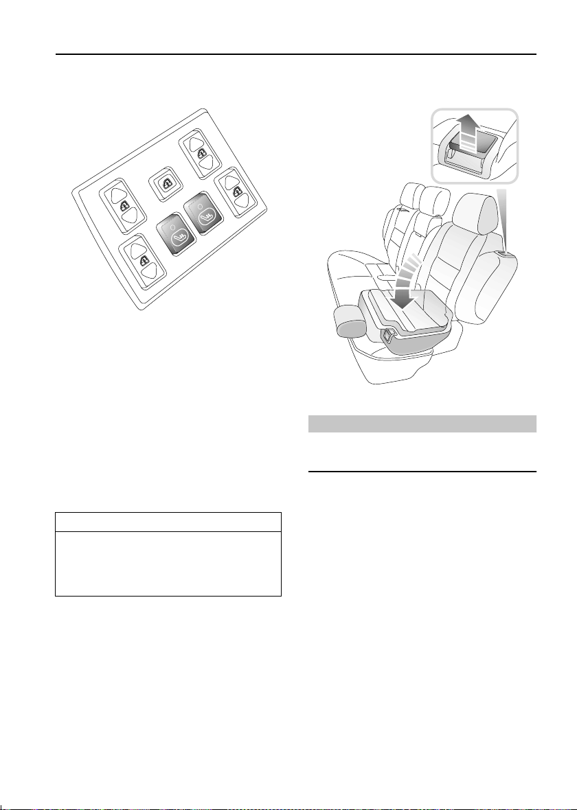
HEATED FRONT SEATS*
H2517
With the starter switch turned on and the
engine running, press the switches to operate
the heating elements in either the driver's or
front passenger seat (the indicator light in the
switch illuminates). Press a second time to
switch off.
The seat heaters are thermostatically controlled
and operate intermittently to achieve and then
maintain a predetermined temperature between
26° - 36°C.
IMPORTANT INFORMATION
The seat heaters consume considerable
power from the battery. For this reason,
they should ONLY be operated while the
engine is running.
FOLDING THE REAR SEATS
H2493
WARNING
DO NOT adjust any part of a seat while the
vehicle is in motion.
One or both parts of the split rear seat can be
either partially or fully folded to further increase
the rear loadspace.
1. To release either part of the backrest, lift
the lever shown in the inset, and then fold
the backrest onto the seat base.
2. Ensure the outer head restraints are fully
lowered, the armrest is stowed and the
centre head restraint is removed.
3. To release the seat base, pull the release
strap upward (arrowed in illustration).
With backrest and seat base released, the
assembly can be folded forward as shown.
27
Page 29
Seats
Returning the seat to the upright position
H2549
Push the seat assembly back onto the floor - the
floor catches should latch with the base of the
seat. Then raise the backrest.
If the backrest cannot be raised easily, DO NOT
force it. This indicates that the seat base has not
fully engaged with the floor catches (note that
the seat assembly is designed to prevent the
backrest from being raised unless the seat is
properly secured to the floor).
With the seat base secure, the backrest can be
raised and locked in position (none of the RED
panel on the release lever should be visible
when the backrest is correctly latched).
WARNING
After the seat is returned to the upright
position, the latching mechanism should be
checked and physically tested to ensure that
both the seat base and backrest are secure
before driving.
Preventing chafing
H3053
When the larger portion (or whole) of the seat
is fully folded, some chafing may occur
between the seat and the cubby box (note that
this is most likely to occur when the front seats
are adjusted fully forward). If chafing is
apparent, risk of damage to the seat cover can
be reduced by fitting the securing strap as
shown.
The strap can be found in the tool bag in the tail
door storage pocket.
1. Fold the backrest forward.
2. Fit one end of the strap to the press-stud
fastening on the underside of the seat
base (it will be necessary to partially raise
the seat base in order to visually locate the
fastening).
3. Stretch the strap around the folded seat
assembly and secure the free end to the
press-stud fastener on the rear of the
backrest.
Compressing the folded seat assembly in this
way should alleviate chafing and any
subsequent damage to the seat cover when the
seat is folded fully.
28
Page 30
Seats
OCCASIONAL REAR SEATS
WARNING
Before driving with passengers seated in the
occasional rear seats, for safety ensure that
the floor latches are fully engaged.
Do not carry passengers in the occasional
rear seats if a dog guard is fitted between the
second row of seats and the loadspace.
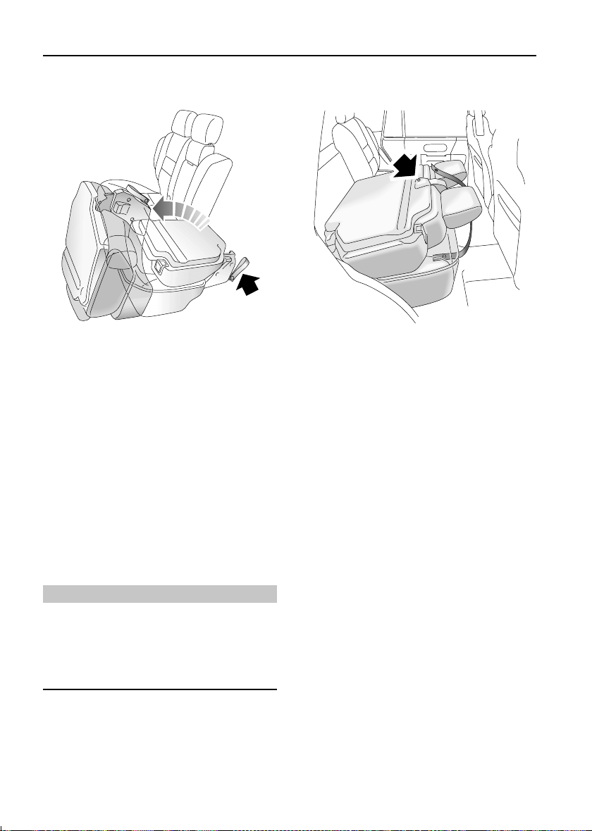
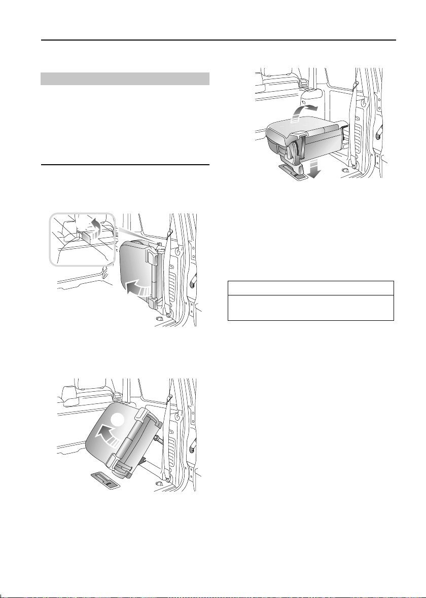
Erecting the seats
1
H3045
4
3
H3047
3. Lower the seat to the loadspace floor,
PUSHING DOWN FIRMLY to ensure that
the floor latch has fully engaged.
4. Pull the backrest into the upright position.
NOTE: The backrest cannot be raised unless the
seat is securely latched to the floor.
IMPORTANT INFORMATION
Remember to unfold the head restraints
from the roof before driving.
1. Push the lever (shown in inset) and hold to
release the seat from its stowed position.
2
H3046
2. Swing the seat away from the vehicle side,
at the same time lifting and turning it
towards the horizontal.
29
Page 31

Seats
Stowing the seats
NOTE: Before stowing a seat, ensure that the
drinks tray to the side of the seat has been
emptied, and that the seat belt buckle is folded
down to prevent it from becoming trapped
between the backrest and cushion.
4
2
1
H3049
1. Push the backrest release lever forward to
unlock the backrest.
2. Fold the backrest fully forward.
3
H3050
3. Turn the twist grip (moving part of the bar
on the back of the seat) fully forward to
release the floor latch, and start to lift the
seat from the loadspace floor.
H3051
4. Continue lifting, at the same time turning
the seat into a vertical position.
5
H3052
5. Push the seat firmly into the vehicle side,
ensuring that the seat has engaged fully
with the securing catch.
30
Page 32

Seats
Head restraints
NOTE: The head restraints for use with the
occasional rear seats are hinged from the roof.
H3544
1. To unfold a head restraint, pull the handle
(arrowed in illustration) forward and
swing the restraint down from the roof.
Stow the head restraint when not in use by
pushing it back flush with the roof.
WARNING
DO NOT drive with occupants in the
occasional rear seats unless the head
restraints are unfolded.
31
Page 33

Seat Belts
Seat Belts
SEAT BELT SAFETY
The seat belts fitted to the front and second row
seats are intended for use by adult sized
occupants. Each belt should be used by one
occupant only.
Observe the following precautions:
• DO make sure ALL passengers are securely
strapped in at all times - even for the
shortest journeys.
• ALWAYS adjust seat belts to eliminate any
slack in the webbing. DO NOT slacken the
webbing by holding the belt away from the
body - to be fully effective, the seat belt
must remain in full contact with the body at
all times.
• ALWAYS fit the lap strap as low on the hips
as possible (never across the abdomen),
and ensure that the diagonal belt passes
across the shoulder without slipping off or
pressing on ethnic.
• DO NOT wear seat belts over hard, sharp or
fragile items in clothing, such as pens, keys,
spectacles etc.
• Always replace a seat belt assembly that has
withstood the strain of a severe vehicle
impact, or if the webbing shows signs of
fraying.
• Where possible use the seat belts to secure
large items of luggage that are to be carried
on the seats - in the event of an accident,
insecure items become flying missiles
capable of causing serious injury.
• DO NOT use a seat belt that is twisted or
obstructed in any way that could impede its
smooth operation.
• DO NOT allow front seat occupants to travel
with the seat backs reclined steeply
rearwards. Optimum benefit is obtained
from the seat belt with the seat back angle
set to approximately 25 degrees from the
upright (vertical) position.
• DO NOT allow foreign matter (particularly
sugary food and drink particles) to enter the
seat belt locks - such substances can render
the locks inoperative.
• In most countries, all occupants are
required by law to wear a seat belt, unless
they have been issued with a medical
exemption certificate.
• During pregnancy, women should wear the
lap belt across the hips below the baby, with
the diagonal belt passing across the
shoulder, between the breasts and to one
side of the baby - if in doubt, consult a
doctor.
WARNING
The airbag supplementary restraint system
(SRS) is designed to add to the overall
effectiveness of the seat belts. It does not
replace them. SEAT BELTS MUST ALWAYS BE
WORN!
Ensure that all seat belts are worn correctly an improperly worn seat belt increases the
risk of death or serious injury in the event of a
collision.
32
Page 34

Seat Belts
SEAT BELTS
To minimise injury in the event of an accident,
it is important that seat belts are worn correctly.
Read the instructions below and the advice
contained under the heading ‘SEAT BELT
SAFETY’.
Fastening the seat belts
H2488
Inertia reel belts are fitted to all front and rear
seating positions, and also to the occasional
rear seats
Pull the belt over the shoulder and across the
chest and, ensuring that the webbing is not
twisted, insert the metal tongue plate into the
buckle nearest the wearer - a ‘CLICK’ indicates
that the belt is securely locked.
Seat belts are designed to bear upon the bony
structure of the body (pelvis, chest and
shoulders) and can only be worn safely with the
seats in a normal upright position - DO NOT
allow front seat occupants to travel with the
seat steeply reclined.
*.
Upper anchorage adjustment (front seats
only)
H2491
The height of the seat belt upper anchorage can
be adjusted for comfort AND safety. Squeeze
the control between finger and thumb to raise
or lower the anchorage. For safety, the seat belt
should always be worn with the webbing
crossing the shoulder MIDWAY BETWEEN THE
NECK AND THE EDGE OF THE SHOULDER.
Ensure the anchorage has ‘clicked’ into one of
the locked positions before driving.
Where possible, rear seat passengers should
adjust their position on the seat to enable the
seat belt webbing to cross the shoulder without
pressing on the neck.
Releasing the belt
Press the RED button on the seat belt buckle.
33
Page 35

Seat Belts
SEAT BELT PRE-TENSIONERS
The seat belt pre-tensioners activate in
conjunction with the airbag SRS and provide
additional protection in the event of a severe
frontal impact on the vehicle (see ‘HOW THE
AIRBAG SRS WORKS’, page 39). The
pre-tensioners automatically retract the seat
belts fitted to the front seats. This reduces any
slack in both the lap and diagonal portions of
the belts, thereby reducing forward movement
of the belt wearer in the event of a severe frontal
collision.
The airbag SRS warning light on the instrument
panel will alert you to any malfunction of the
seat belt pre-tensioners.
If the pre-tensioners have been activated, the
seat belts will still function as restraints, and
must be worn in the event that the vehicle
remains in a driveable condition.
NOTE: The seat belt pre-tensioners will NOT be
activated by rear, side or minor frontal impacts.
IMPORTANT INFORMATION
The seat belt pre-tensioners will only be
activated once and then MUST BE
REPLACED by a Land Rover dealer. Failure
to replace the pre-tensioners will reduce
the efficiency of the vehicle's front restraint
systems.
After any frontal impact, always have the
seat belts and pre-tensioners checked and,
if necessary, replaced by a Land Rover
dealer.
In the interests of safety, it is
recommended that removal or replacement
of the front seats and seat belts should
only be carried out by a Land Rover dealer.
CARING FOR SEAT BELTS
Regularly inspect the belt webbing for signs of
fraying, cuts and wear; also pay particular
attention to the condition of the fixing points
and adjusters.
DO NOT bleach or dye the webbing and avoid
contaminating the webbing with polish, oil or
chemicals (see ‘CLEANING THE INTERIOR’,
page 161).
Testing inertia reel belts
• With the seat belt fastened, give the
webbing near the buckle a quick upward
pull. The buckle must remain securely
locked.
• With the seat belt unfastened, unreel the
webbing to the limit of its travel. Check that
unreeling is free from snatches and snags
and then allow the belt to FULLY retract.
• Partially unreel the webbing, then hold the
tongue plate and give it a quick forward pull.
The mechanism must lock automatically
and prevent any further unreeling.
If a seat belt should fail any of these tests,
contact your dealer immediately.
WARNING
Always replace a seat belt that shows signs of
webbing damage or has withstood the strain
of a severe vehicle impact.
34
Page 36

Child Restraints
Child Restraints
CHILD SEATS
The seat belts fitted to your vehicle are
designed for adults and larger children. It is
very important that all infants and young
children are restrained in a suitable child safety
seat appropriate to their age and size. Safety
seats approved for use in your vehicle are
available from your Land Rover dealer.
Only fit a child seat that has been approved for
use in your vehicle, and ensure the
manufacturer's fitting instructions are followed
exactly.
Vehicles fitted with a passenger airbag
For optimum safety, children should travel in
the rear of the vehicle at all times. However, if a
passenger airbag is fitted and it is essential that
a child travel in the front, set the seat fully
rearward and seat the child in an approved,
FORWARD FACING child seat. DO NOT use a
rear facing child seat - an inflating airbag could
impact with the seat and cause serious injury to
the child!
The above symbol affixed to the passenger side
fascia panel of your vehicle, warns against the
use of a REAR FACING child seat in the front
passenger seat, when a passenger airbag is
fitted. This type of child seat could cause
serious injury to a child in the event of an airbag
deployment.
WARNING
DO NOT install a rearward facing child seat in
a passenger seat equipped with an airbag
system. Failure to follow this advice could
result in serious injury, or even death for the
child.
Seat belt locking mechanism
All front passenger and second row seat belts
have a special locking mechanism which aids
the retention of child seats. The procedure to
install a child seat is as follows:
1. Install the child seat in the vehicle, attach
the seat belt and secure the buckle in
accordance with the manufacturers fitting
instructions.
2. Pull on the shoulder section of the belt to
unreel all of the remaining webbing to the
limit of its travel. This will engage the
automatic locking feature, which then acts
as a ratchet, allowing the webbing to
retract ONLY.
3. Allow the seat belt to retract onto the child
seat (a ‘clicking’ sound will confirm that
the ratchet has engaged), firmly pushing
the child seat into the seat.
4. Ensure there is no slack in the seat belt by
pulling upwards on the shoulder belt
immediately above the child restraint. The
seat belt should now be locked and the
child seat held firmly in position.
Once the child seat is removed and all the seat
belt webbing is allowed to retract, the seat belt
locking mechanism reverts to normal
operation.
NOTE: The automatic locking mechanism
should also be used when securing large items
of luggage to a seat.
35
Page 37

ISOFIX CHILD RESTRAINTS
H3675
Child Restraints
In some markets, child restraint systems
complying with International Standard
Organisation regulations and approved for
fitiing in your vehicle may be available. These
restraints are different to convential child seats,
requiring anchor bars built into the vehicle seat
in order to accept the ISOFIX locking
mechanism.
Both outer, rear (second row) seating positions
inyou rvehicle are equipped to accept ISOFIX
restraints.
WARNING
DO NOT attempt to fit ISOFIX restraints to the
centre seating position - the anchor bars are
not designed to hold an ISOFIX restraint in
this position
36
Page 38

Child Restraints
Fitting ISOFIX child restraints
ISOFIX child restraints should only be fitted in
the two outer seating positions of the second
row seats. Anchor bars built into the rear seat
frame enable the ISOFIX restraints to be
securely attached to the vehicle seat in these
positions only. The anchor bar locations are
shown in the illustration above.
When fitting ISOFIX child restraints, always
follow the instructions supplied by the
manufacturer of the restraint.
Once the ISOFIX restraint is installed, you are
recommended to test the security of the
installation before seating the child. Attempt to
twist the restraint from side to side and to pull
the restraint away from the vehicle seat; then
check that the anchors are still securely in
place.
WARNING
If the restraint is not correctly anchored, there
is a significant risk of injury to the child in the
event of a collision or emergency braking.
37
Page 39

Airbag SRS
Airbag SRS
H2628
AIRBAG SRS
The airbag supplementary restraint system
(SRS) provides additional protection for either
the driver, or the driver and front seat
passenger, in the event of a severe frontal
impact on the vehicle.
Provided the front seat occupants are correctly
seated, with seat belts properly worn, the
airbags will provide additional protection to the
chest and facial areas in the event of the car
receiving a severe frontal impact.
WARNING
The airbag is a supplementary restraint
system that provides ADDITIONAL protection
in a frontal impact only - it does NOT replace
the need to wear a seat belt. For maximum
safety protection in all crash situations, a
seat belt must be worn.
NOTE: Inflation and deflation of the airbags
takes place very quickly and will not protect
against the effects of secondary impacts that
may occur.
The airbag(s) are located in the centre pad of
the steering wheel and, where fitted, in the
fascia panel above the glovebox.
WARNING
Do not allow a front seat passenger to
obstruct the operation of the airbag by placing
feet, knees or any other part of the person, or
any other objects in contact with, or in close
proximity to, an airbag module.
38
Page 40

Airbag SRS
To ensure correct deployment of the airbags, it
is essential that obstructions are not allowed to
intervene between an airbag and the occupant.
The following are examples of the type of
obstructions that could either, impede correct
operation of the airbags, or jeopardise personal
safety in the event of an airbag deployment:
• Accessories attached to or obscuring an
airbag cover.
• Items of hand luggage, or other objects
placed on an airbag cover.
• Feet, knees or any other part of the anatomy
in contact with, or in close proximity to, an
airbag cover.
WARNING
DO NOT attach or position items on or to an
airbag cover (steering wheel centre pad or
fascia panel), which could interfere with the
inflation of the airbag or, if the airbag
inflates, be propelled inside the car causing
injury to the occupants.
Seating positions
In order to provide optimum protection in the
event of a severe impact, it is necessary for the
airbags to deploy with considerable speed.
An inflating airbag can cause facial abrasions
and other injuries if the occupant is too close to
the airbag at the time of its deployment.
HOW THE AIRBAG SRS WORKS
In the event of a collision, the airbag control
unit monitors the rate of deceleration or
acceleration induced by the collision, to
determine whether the airbags should be
deployed.
Operation of the airbag SRS is dependent
entirely on the rate at which the vehicle's
passenger compartment changes speed as a
result of a collision. The circumstances
affecting different collisions (vehicle speed,
angle of impact, type and size of object hit, for
example), vary considerably and will affect the
rate of acceleration or deceleration accordingly.
NOTE: The airbag SRS is not designed to
operate as a result of rear collisions, minor
frontal or side Impacts, roll over accidents; nor
will it operate as a result of heavy braking or
driving over bumps and potholes.
It follows, therefore, that significant superficial
damage can occur without the airbags
deploying or, conversely, that a relatively small
amount of structural damage may cause the
airbags to be deployed.
Airbags will only deploy when they are
required to supplement the restraining force
of the seat belts.
In the case of a severe frontal collision, both
front airbags and seat belt pre-tensioners will
be deployed.
WARNING
To minimise the risk of accidental Injury from
inflating airbags, seat belts should be
correctly worn at all times. In addition, both
driver and front seat passenger should adjust
their seat to provide the maximum practical
distance from the airbags.
39
Page 41

Airbag SRS
H2474
Airbag inflation is virtually instantaneous and
occurs with considerable force, accompanied
by a loud noise. The inflated bag, together with
the seat belt restraint system, limit the
movement of a front seat occupant, thereby
reducing the risk of injury to the head and upper
torso.
WARNING
An inflating airbag can cause facial abrasions
and other injuries. Minimise the risk of injury
by ensuring that front seat occupants are
wearing their seat belts and are seated
correctly, with the seat as far back as is
practical.
Airbag SRS warning light
A warning light mounted on the instrument
panel will alert you to any malfunction of the
airbag SRS. The airbag SRS should always be
checked by a dealer if any of the following
symptoms occur:
• The warning light fails to illuminate when
the starter switch is turned to position ‘II’.
• The warning light fails to extinguish within
approximately four seconds after the starter
switch is turned to position ‘II’.
• The warning light illuminates after the
engine is started, or while the vehicle is
being driven.
When an airbag inflates, a fine powder is
released. This is not an indication of a
malfunction, however, the powder may cause
irritation to the skin and should be thoroughly
flushed from the eyes and any cuts or abrasions
of the skin. After inflation the airbags deflate
immediately. This provides a gradual
cushioning effect for the occupant and also
ensures that the driver's forward vision is not
impaired.
NOTE: After inflation, some airbag components
are hot - DO NOT touch until they have cooled.
40
Page 42

Airbag SRS
SERVICE INFORMATION
WARNING
DO NOT attempt to service, repair, replace,
modify or tamper with any part of the airbag
SRS, or wiring in the vicinity of an airbag SRS
component; this could cause the system to
activate, resulting in personal injury.
After ten years from the original date of
registration (or the installation date of a
replacement airbag SRS), some components
will need to be replaced by a Land Rover dealer
(note the ‘airbag module replacement date’
shown on page 2 of the Service Portfolio book).
In addition, ALWAYS contact your dealer if:
• an airbag inflates.
• the front of the vehicle is damaged, even if
the airbag has not inflated.
• any part of an airbag module cover (the
steering wheel centre pad or fascia panel)
shows signs of cracking or damage.
IMPORTANT INFORMATION
The components that make up the airbag
SRS are sensitive to electrical or physical
interference, either of which could easily
damage the system and cause inadvertent
operation or a malfunction of the airbag.
For your safety it is recommended that you
seek the assistance of a Land Rover dealer
to carry out any of the following:
• Removal or repair of any wiring or
component in the vicinity of any of the
SRS components (yellow wiring
harness), including the steering wheel,
steering column, instrument and fascia
panels.
• Installation of electronic equipment
such as a mobile phone, two-way radio
or in-car entertainment system.
• Modification to the front of the vehicle,
including the bumper and chassis.
• Attachment of accessories to the front
of the vehicle.
Disposing of vehicles
If you sell your vehicle, be sure to inform the
new owner that the vehicle has an airbag SRS.
In addition, make sure the new owner is aware
of the airbag module replacement date shown
on page 2 of the Service Portfolio book.
If your vehicle is to be scrapped; uninflated
airbags are potentially very dangerous and
must be safely deployed in a controlled
environment by qualified personnel, before a
vehicle is scrapped.
41
Page 43

Steering Column
Steering Column
STEERING COLUMN ADJUSTMENT
H2533
The angle of the steering column can be
adjusted to suit your driving position:
1. With the vehicle stationary, push the
locking lever up and hold in this position.
2. Move the steering wheel (up or down) into
the desired position, making sure the
instrument panel is clearly visible.
3. When adjustment is complete, release the
locking lever to lock the steering column
in position.
WARNING
DO NOT adjust the steering column while the
vehicle is in motion. This is extremely
dangerous!
42
Page 44

Door Mirrors
Door Mirrors
EXTERIOR MIRRORS
NOTE: Objects viewed in exterior mirrors may
appear further away than they actually are.
Manually adjustable mirrors
Manually adjustable mirrors are fitted to some
vehicles - move the mirror glass to the required
position.
Electrically adjustable mirrors
H2629
• Turn the control to the ‘L’ or ‘R’ position to
select either the left or right hand mirror.
• With the starter switch turned to position
‘II’, push the control in the appropriate
direction to tilt the mirror glass up/down/left
or right.
• When adjustment is complete, return the
control to the OFF position (midway
between ‘L’ and ‘R’).
NOTE: In some markets the door mirrors have
integral heating elements which disperse ice or
mist from the glass. These will operate in
conjunction with the heated rear window.
43
Page 45

Door Mirrors
Folding the mirror body
The door mirrors are designed to fold forwards
or rearwards on impact. They can also be folded
back towards the side windows into a ‘park’
position to enable the vehicle to negotiate
narrower openings.
H2981
3. Before driving, push the control down a
second time to return the mirrors to their
normal (extended) position.
If the mirrors are accidentally knocked out of
position (i.e. with one mirror extended and the
other in the ‘parked’ position), an additional
operation of the switch will re-synchronise
them.
Manual operation: On some vehicles this
operation can be carried out manually by
physically pushing the mirror bodies back
towards the side windows, and then pulling
them back into the normal (extended)
positions.
Electric operation: On some vehicles mirror
folding can be carried out electrically as
follows:
1. Ensure the mirror control is turned to the
centre position.
2. With the starter switch turned to position
‘II’, push the control down once to fold the
mirrors back towards the side windows.
44
Page 46

Instruments
km
INSTRUMENT PANEL
Instruments
2
H2618a
1. Temperature gauge
Once the engine coolant has reached its normal
operating temperature, the pointer will rise to a
position within the WHITE segment of the
gauge (the precise position will vary according
to climatic conditions).
If the pointer moves towards the RED segment,
this indicates that the engine coolant is
becoming too hot. Should the pointer move
INTO the RED segment and the RED warning
light within the gauge illuminates, severe
engine damage could occur (under these
circumstances, the air conditioning may switch
off and engine performance may reduce in
order to minimise engine load).
Stop the vehicle as soon as safety permits and
allow the engine to idle for five minutes in order
to cool down - DO NOT SWITCH OFF. Seek
qualified assistance before continuing.
3
53
00
km
45 61
2. Tachometer
Indicates engine speed in revolutions per
minute (x 1000). In normal driving conditions
the engine is most fuel efficient between 2000
and 3000 rev/min.
Vehicles equipped with a catalytic converter are
fitted with a system which automatically
restricts the number of engine revolutions per
minute once the engine's maximum ‘governed’
speed has been reached.
3. Speedometer
Indicates road speed in kilometres per hour.
45
Page 47

Instruments
4. Total distance (odometer) and trip recorder
With the starter switch turned to position ‘II’,
the display indicates the total distance travelled
by the vehicle, and also shows the most recent
individual journey distance.In some markets,
the display can be set to show either miles or
kilometres. To convert from one to another,
press and hold the trip recorder reset button for
more than two seconds.
NOTE: On automatic gearbox vehicles the
display also indicates which selector position is
selected.
5. Trip recorder reset button
Press briefly to return the trip recorder display
to zero.
6. Fuel gauge
The pointer drops to zero when the starter
switch is turned off, but quickly rises to show
the level of fuel in the tank when the switch is
turned to position ‘II’. After refuelling, the
gauge rapidly rises to reflect the increase of fuel
in the tank.
When the fuel remaining in the tank is a
minimum of 14 litres on petrol vehicles, or
9 litres on diesel vehicles, the AMBER low fuel
warning light in the fuel gauge illuminates. If the
light illuminates, refuel at the first opportunity.
The small arrow visible below the fuel pump
symbol on the gauge indicates the side of the
vehicle on which the fuel filler is located - a
useful reminder to help you position the vehicle
on the correct side of the forecourt pumps
before refuelling.
WARNING
NEVER allow petrol engined models to run out
of fuel (the resultant misfire may destroy the
catalytic converter).
46
Page 48

Warning Lights
53
00
km
INSTRUMENT PANEL
H2631a
Warning Lights
The location and specification of the warning
lights may vary according to model and market
requirements.
Check engine - AMBER*
The light illuminates as a bulb and
system check when the starter
switch is turned on, and
extinguishes as soon as the engine is started.
Illumination at any other time indicates an
engine fault - if the light illuminates while
driving, avoid high speeds and seek qualified
assistance urgently.
Airbag SRS - RED
The light illuminates when the
starter switch is turned to position
‘II’ and extinguishes after about 4
seconds. If the light illuminates at any other
time, the system is faulty - seek
qualified assistance urgently.
Handbrake, brake fluid - RED
The light illuminates for about 3
seconds as a bulb check when the
starter switch is turned on. It also
illuminates when the handbrake is applied with
the starter switch in position ‘II’.
The light should extinguish when the handbrake
is fully released or shortly after the electrical
circuits are switched on. If the light illuminates
whilst driving, a fault with the braking system is
indicated. Stop the vehicle as soon as safety
permits and seek qualified assistance before
continuing.
Low oil pressure - RED
The light illuminates as a bulb
check when the starter switch is
turned to position ‘II’ and
extinguishes when the engine is started. If the
light remains on, flashes on and off, or
illuminates whilst driving, stop the vehicle as
soon as safety permits and SWITCH OFF
THE ENGINE IMMEDIATELY. Seek qualified
assistance before driving. Always check the oil
level when this light illuminates.
47
Page 49

Warning Lights
Transmission oil temperature - RED*
Illuminates as a bulb check when
the starter switch is turned to
position ‘II’ and extinguishes after
3 seconds approx. If the light illuminates while
driving, the gearbox oil temperature is too high
(most likely to occur in very hot weather during
continuous high speed driving, or whilst towing
heavy loads on steep inclines or if the
handbrake has been applied while driving).
If the light illuminates, reduce speed. If the light
remains on, stop the vehicle and allow the
gearbox to cool. Do not drive until the light has
extinguished. (Depending on the ambient
temperature and the carrying loads imposed on
the vehicle, it may take several minutes before
the light extinguishes and it is safe to drive).
Anti-lock braking system - AMBER
The light illuminates as a bulb and
system check when the starter
switch is turned to position ‘II’. If
the light illuminates whilst driving or remains
illuminated after the starter switch is turned on,
a fault has occurred. This means that full ABS
control may not be available and you should
seek qualified assistance urgently.
NOTE: Faults which cause the ABS light to
illuminate after the initial system checks, or
whilst driving, will be accompanied by a
warning chime sounding 3 times.
Headlight main beam - BLUE
Illuminates when the headlights
are switched to main beam.
Direction indicators - GREEN
The left or right warning light
flashes in time with the
corresponding left or right
direction indicator lights whenever they are
operated. If the warning light fails to flash, or
flashes very rapidly, this may indicate a bulb
failure in one of the direction indicator lights.
If the hazard switch is pressed, both warning
lights will flash in conjunction with the direction
indicator lights.
Trailer direction indicators - GREEN
The light illuminates briefly as a
bulb check when the starter switch
is turned to position ‘II’. If a trailer
is attached, the light illuminates in conjunction
with the vehicle direction indicator lights to
show that all trailer indicator lights are
functioning correctly. In the event of a bulb
failure on the trailer, the warning light remains
off.
Glow plug - AMBER (diesel only)
Illuminates when the starter switch
is turned to position ‘II’. Wait for
the light to extinguish before
starting the engine.
Battery charging - RED
The light illuminates as a bulb
check when the starter switch
is turned to position ‘II’ and
extinguishes once the engine is running. If it
remains on, or illuminates whilst driving, a fault
is indicated. Seek qualified assistance urgently.
Seat belt - RED
approximately 6 seconds, even if the driver's
48
*
The light illuminates when the
starter switch is turned to position
‘II’ and extinguishes after
Page 50

Warning Lights
seat belt remains unfastened. In some markets
illumination of the light will be accompanied by
a warning chime (see ‘AUDIBLE WARNINGS’,
page 52)
Hill descent control (HDC) ‘information’ GREEN
Illuminates briefly as a bulb and
system check when the starter
switch is turned to position 'II' and
also when HDC is selected.
If HDC is selected when Low Range gears are
engaged the light will illuminate continuously
indicating that HDC is active.
When HDC is selected and non-operating gears
are engaged (i.e. High range), the light will flash
to inform the driver that HDC is selected, but
will not operate.
If the light starts to flash while HDC is active,
normal functionality may seize and HDC ‘fade
out’ may be induced (see ‘HILL DESCENT
CONTROL’, page 112).
Hill descent control (HDC) ‘failure’ - AMBER
The light illuminates briefly as a
bulb and system check when the
starter switch is turned to position
‘II’.
If the light illuminates at any other time, either
a fault has occurred which affects the
functionality of the system, or over-use of the
system has been detected, in which case HDC
may ‘fade out’ (see ‘HILL DESCENT CONTROL’,
page 112).
NOTE: Faults which cause the HDC ‘failure’ light
to illuminate after the initial system checks, or
whilst driving, will be accompanied by a
warning chime sounding 3 times.
49
Page 51

Warning Lights
Traction Control - AMBER
Illuminates as a bulb check when
the starter switch is turned to
position ‘II’ and extinguishes after
approximately 3 seconds. The light illuminates
for a minimum of 2 seconds, whenever traction
control is operating.
If the light illuminates continuously, and
remains illuminated when the vehicle is
stationary, a fault with the system is indicated;
seek qualified assistance.
NOTE: Faults which cause the light to illuminate
after the initial system checks, or whilst driving,
will be accompanied by a warning chime
sounding 3 times.
Active cornering enhancement (ACE) RED/AMBER
RED illumination changes to AMBER, and after
a further two seconds, the light extinguishes.
If illumination occurs while driving, a fault
with the system is indicated, as follows:
• If the light shows RED (a flashing red light
which changes to constant illumination after
two minutes, and is accompanied by a
warning chime): This indicates a system
fault that may result in serious damage to
vehicle components and reduced ACE
performance. Stop the vehicle as soon as
safety permits and switch off the engine. DO
NOT CONTINUE DRIVING! Seek qualified
assistance immediately.
*
The light illuminates RED when the
starter switch is turned to
position ‘II’. After two seconds, the
• If the light shows AMBER (constant
illumination): This indicates a system fault
that will result in reduced ACE performance
but will not leave the vehicle in a dangerous
condition. You may continue driving, but
reduce speed, take additional care, and
consult a Land Rover dealer at the earliest
opportunity.
Fuel filter - AMBER (diesel only)
Illuminates as a bulb check when
the starter switch is turned to
position ‘II’ and extinguishes after
3 seconds approximately. If the light
illuminates while driving, this indicates the
presence of excessive amounts of water in the
fuel. You may continue driving but should seek
qualified assistance at the earliest convenient
time.
Off Road - AMBER
then extinguishes.
If the off-road switch is pressed:
The light flashes continually while the rear of
the vehicle is either; rising to off-road height, or
returning to standard ride height. The light
illuminates constantly while the suspension
remains at off-road height.
In addition, the light will flash if extended mode
is induced.
*
Illuminates briefly as a bulb and
system check when the starter
switch is turned to position ‘II’ and
50
Page 52

Warning Lights
Manual mode - GREEN (Auto only)
Illuminates for 3 seconds as a bulb
check when the starter switch is
turned to position ‘II’. Illuminates
constantly while Manual mode is selected.
NOTE: If both the Manual and Sport mode lights
(shown below) flash together, this indicates an
electrical fault with the automatic gearbox. If
the lights continue flashing after the vehicle has
been brought to a halt and the starter switch
has been turned off and then on again, you
should seek qualified assistance urgently.
Sport mode - GREEN (Auto only)
Illuminates for 3 seconds as a bulb
check when the starter switch is
turned to position ‘II’. Illuminates
constantly while Sport mode is selected.
Self-levelling suspension - AMBER
Illuminates briefly as a bulb and
system check when the starter
switch is turned to position ‘II’ and
then extinguishes.
If the remote handset is operated:
The light flashes continually while the rear of
the vehicle is being lowered, or raised.
If the light illuminates constantly:
A fault with the suspension is indicated. Seek
qualified assistance as soon as possible.
While it is possible to continue driving the
vehicle in this condition, there is a considerable
risk of causing further damage to the
suspension. Preferably, the vehicle should be
brought to a halt as soon as conditions allow.
Further travel should be limited to reaching the
nearest Land Rover dealer, or driving to a place
of safety while awaiting recovery. In any event,
speed must be restricted to a rate that will
guarantee a smooth, and totally bump-free, ride
at all times, ideally traversing only smooth,
metalled roads.
*
51
Page 53

Audible Warnings
Audible Warnings
AUDIBLE WARNINGS
The market specification will determine which
of the following audible warnings are
appropriate to your vehicle.
Lights on reminder
If the lights are left on after the starter switch is
turned off, a warning chime will sound when the
driver's door is opened. The chime will cease as
soon as the lights are switched off or when the
driver's door is closed.
Transfer box reminder
A warning will chime continuously while the
transfer gearbox is in neutral.
Self-levelling suspension warning
• A single warning will chime whenever the
off-road switch is operated to raise the
vehicle to off-road height, or to return it to
standard ride height.
• A warning will chime continuously while the
remote handset is used to lower the vehicle
from standard ride height, and also while
returning the vehicle to standard ride height.
• A warning chime will sound 3 times if
changes to or from off-road height are
requested but not permitted.
ABS warning
If a fault with the anti-lock braking system is
detected, a warning will chime three times. You
may continue driving, but should understand
that full ABS control may not be available.
Consult your dealer at the earliest opportunity.
HDC warnings
• A warning will chime continuously in
conjunction with the HDC warning light
flashing green, whenever HDC has been
selected but the system's operating criteria
have not been met.
• A warning will chime continuously and the
HDC failure warning light will illuminate
(amber), whenever a fault is detected with
the HDC system.
• A single warning will chime when HDC is
deselected.
Starter key reminder
If the key is left in the starter switch while the
driver's door is open, a warning will chime
continuously. The chime stops as soon as the
door is closed or the key is removed from the
starter switch.
Seat belt reminder
In some markets, if the driver's seat belt has not
been fastened when the starter switch is turned
on, a warning chime will sound (one second
frequency). The chime operates in conjunction
with the seat belt warning light and sounds for
6 seconds, or until the seat belt is fastened
(whichever occurs first).
In Gulf States markets, either; the chime will
continue sounding indefinitely until the seat belt
is fastened, or; the chime will sound for 6
seconds whenever the driver's door is opened
and closed with the starter switch turned on.
ACE warning
A single warning will chime if a fault with the
active cornering enhancement system is
detected. The chime will coincide with the ACE
warning light flashing RED.
52
Page 54

Lights & Indicators
Lights & Indicators
DIRECTION INDICATORS
H2582
Move the lever DOWN to indicate a LEFT turn,
and UP to indicate a RIGHT turn (the
appropriate GREEN warning light on the
instrument panel will flash in time with the
direction indicators).
Hold the lever part-way up or down against
spring pressure to indicate a lane change.
LIGHTS
2
1
H2448
Side, tail and instrument panel lights
Turn lighting switch to position 1.
Headlights
Turn lighting switch to position 2.
Headlight main and dipped beams
H2449
Pull the lever fully towards the steering wheel to
change headlight beams (BLUE warning light
glows when the headlights are on main beam).
To flash the headlights, pull the lever part way
towards the steering wheel and release.
53
Page 55

Lights & Indicators
Headlight levelling*
H2632
The angle of the headlight beams is affected by
the distribution of weight inside the vehicle. The
headlights should be adjusted so that the point
at which the beams meet the road surface
ahead of the vehicle provides adequate
illumination without dazzling other road users.
The four-position switch should be used to
adjust the headlight beams in relation to the
vehicle loadings identified opposite.
Models with Coil suspension
Position Loading Condition
0 Driver, or driver and front
passenger only
(loadspace empty).
1 All seats occupied
(loadspace and occasional
rear seats empty)
2 All seats occupied with
loadspace loaded to max.
permissible rear axle weight.
3 Driver only with loadspace
loaded to max. permissible
rear axle weight.
Models with Air suspension
Position Loading Condition
0 Driver, or driver and front
passenger only
(loadspace empty).
1 All seats occupied
(loadspace and occasional
rear seats empty)
2 All seats occupied with
loadspace loaded to max.
permissible rear axle weight.
2 Driver only with loadspace
loaded to max. permissible
rear axle weight.
Note that the loading criteria differs for vehicles
with conventional coil spring suspension,
compared with those fitted with air suspension
(if in doubt, air suspension vehicles can be
identified by the fascia-mounted off-road
switch).
54
Page 56

Lights & Indicators
FOG LIGHTS
H3545
Front fog lights*
Press to operate, press a second
time to switch off (the indicator
light in the switch illuminates when
the fog lights are switched on).
The fog lights can be operated ONLY when the
starter switch is at position ‘II’ and the side or
headlights are also switched on. The fog lights
extinguish automatically when the side lights or
the starter switch is turned off.
Rear fog guard lights
Press to operate, press a second
time to switch off (the indicator
light in the switch illuminates when
the fog guard lights are switched on). The rear
fog guard lights illuminate ONLY when the
headlights (or front fog lights) are also
switched on, and the starter switch is turned to
position ‘II’. Switching off the headlights, or
front fog lights, or turning the starter switch to
position ‘0’ will automatically extinguish the
rear fog guard lights too (the lights will not
illuminate again unless switched on).
ALWAYS remember to switch the fog guard
lights off as soon as visibility permits; in clear
conditions fog guard lights can dazzle other
road users!
55
Page 57

Lights & Indicators
HAZARD WARNING LIGHTS
H3546
Press to operate; all the direction
indicator lights (including those
fitted to a trailer) will flash
together. Use ONLY in an emergency to warn
other road users when your stationary vehicle
is causing an obstruction, or is in a hazardous
situation. Remember to switch off before
moving away.
56
Page 58

Wipers & Washers
Wipers & Washers
OPERATING
The wipers and washers will only operate when
the starter switch is turned to position ‘I’ or ‘II’.
WINDSCREEN WIPERS
3
IMPORTANT INFORMATION
• DO NOT operate the wipers on a dry
screen.
• In freezing or very hot conditions,
ensure that the blades are not frozen or
stuck to the glass.
• In winter, remove any snow or ice from
around the arms and blades, including
the wiped area of the windscreen and
the heater air intakes.
NOTE: If the wiper blades have stuck to the
glass, a thermal cut-out may temporarily
prevent the wiper motor from operating. If this
is the case, switch the wipers off, free them
from the obstruction and then switch on again.
2
1
H2450
Intermittent wipe
Turn switch to position 1.
Normal speed wipe
Turn switch to position 2.
Fast speed wipe
Turn switch to position 3.
NOTE: If the front screen wipers are operating
(in either intermittent or continuous mode), the
rear wiper operates automatically whenever
reverse gear is selected.
57
Page 59

Wipers & Washers
Single wipe
H2583
Pull the lever down and release immediately.
NOTE: With the lever held down, the wipers will
operate at high speed until the lever is released.
Variable delay (intermittent wipe)
WINDSCREEN WASHER
H2452
Pull the lever towards the steering wheel. The
windscreen wipers will operate in conjunction
with the washers for as long as the lever is held
in this position, the wipers continuing for a
further 4 seconds after the lever is released.
HEADLIGHT WASHERS*
When the headlights are illuminated, the
headlight washers operate automatically in
conjunction with every third operation of the
windscreen washers.
H2451
Rotate the switch to vary the delay between
wipes.
58
Page 60

Wipers & Washers
REAR WINDOW WIPER AND WASHER
H3547
Rear window wash/wipe
Press and hold switch for the
required duration of window
washing. The wiper operates
automatically during washing and continues for
a further 3 wipes after the switch is released.
Rear window wiper
Press to operate: after
continuously wiping 3 or 4 times,
the wiper operates intermittently
until switched off.
NOTE: When reverse gear is selected, the rear
wiper will operate either continuously or
intermittently in tandem with the front wipers.
59
Page 61

Horn
HORN
H2586
To operate, press either of the horn switches
set into the steering wheel pad.
Horn
60
Page 62

Electric Windows
ELECTRIC WINDOWS
3
1
2
Electric Windows
Accidental closing of an electrically operated
window on fingers, hands or any vulnerable
5
4
part of the body, can result in serious injury.
Always observe the following precautions:
ISOLATE the rear window switches when
carrying children.
ENSURE children are kept clear whilst raising
or lowering windows.
ENSURE that all adult pass engers are familiar
with the controls and the potential dangers of
electrically operated windows.
WARNING
H2573
The switches on the centre console operate the
windows as follows:
1. Right hand front window.
2. Left hand front window.
3. Right hand rear window.
4. Left hand rear window.
5. Isolating switch for rear door window
switches.
NOTE: Rear windows can also be operated by
the individual switches mounted on each rear
door, provided the isolation switch has not
been activated.
Operating the windows
The electric windows can be operated when the
starter switch is at position ‘II’ and for up to 45
seconds after the starter switch is turned to
position ‘0’ (provided a door is not opened in
the meantime).
Press and HOLD the bottom of a switch to lower
and the top of a switch to raise. The window will
stop moving as soon as the switch is released.
‘One touch’ down (Front windows only)
By briefly pressing (and then releasing) the
bottom of a switch, a front window will open
fully at a single touch. Window movement can
be stopped at any time by BRIEFLY pressing the
top of the switch.
Rear window isolation switch
Press once to isolate the rear window switches;
press a second time to restore independent
control.
61
Page 63

Sunroof
Sunroof
MANUAL SUNROOF*
A
H2453
Pull the operating handle from its recess until it
locks in position (see inset). The roof can be
opened in two separate phases as follows:
• To tilt the roof: depress the locking button
‘A’ and rotate the handle clockwise ONE
COMPLETE TURN.
• To fully open the roof: depress the button
again and continue turning clockwise.
To close the roof: rotate the handle
anti-clockwise.
Sunroof roller blind
H2477
Pull the sunroof blind across the sunroof
aperture and secure the hook on the blind to the
front edge of the sunroof cassette.
NOTE: The sunroof can still be opened and
closed with the sunroof blind in position.
WARNING
ENSURE the sunroof is not obstructed when
opening or closing.
DO NOT allow passengers to extend any part
of their bodies through the sunroof aperture
while the vehicle is moving - injury from
flying debris, branches of trees or other
obstructions could occur.
ALWAYS close the roof when the vehicle is
unattended.
62
Page 64

Sunroof
ELECTRIC SUNROOF*
2
1
H2528
1. Front sunroof operating switch
2. Rear sunroof disable switch.
(Always disable the rear sunroof when
driving with children in the rear of the
vehicle).
3. Rear sunroof operating switch.
NOTE: Vehicles fitted with a rear sunroof
have an additional operating switch set
into the roof lining forward of the rear
sunroof.
The electric sunroof can be operated when the
starter switch is at position ‘II’, and for up to 45
seconds after the starter switch is turned off
(provided a door is not opened in the
meantime).
The roof opens in two separate phases as
follows:
• To tilt the roof: press the upper part of the
switch once BRIEFLY - the rear edge of the
roof automatically rises to the tilted
position.
3
• To open the roof: press the upper part of the
switch BRIEFLY a second time - the roof
remains tilted and slides towards the rear
until it is fully open or until movement is
stopped by briefly pressing the lower part of
the switch.
To close the roof: press and hold the lower part
of the switch until the roof has moved to the
required position.
The roof will pause momentarily when it
reaches the tilt position.
NOTE: If the roof is obstructed for more than 7
seconds whilst opening or closing, an
automatic cut-out will prevent the sunroof
motor from operating. After a period, operation
of the motor will be restored.
WARNING
Accidental closure of a sunroof on fingers,
hands or any vulnerable part of the body, can
result in serious personal injury. Always
observe the following precautions:
ENSURE the sunroof is not obstructed when
opening or closing.
ENSURE that all adult pass engers are familiar
with the controls and the potential dangers of
operating an electrically operated sunroof.
DO NOT allow passengers to extend any part
of their bodies through the sunroof aperture
while the vehicle is moving - injury from
flying debris, branches of trees or other
obstructions could occur.
ALWAYS close the roof when the vehicle is
unattended.
63
Page 65

Sunroof
Sunroof roller blind
H2477
Pull the sunroof blind across the sunroof
aperture and secure the hook on the blind to the
front edge of the sunroof cassette.
NOTE: The sunroof can still be opened and
closed with the sunroof blind in position.
64
Page 66

Heating & Ventilation
VENTILATION
Heating & Ventilation
1
H3548
The ventilation system provides fresh or heated
air to the interior of the vehicle from the air
intake grille in front of the windscreen.
NOTE: Always keep the air intake grille clear of
obstructions such as leaves, snow or ice.
Air outlets are provided to the windscreen, face
and feet - the location of those vents is shown
in the illustration above. The temperature of the
air supplied to the vents is controlled by the
heater.
NOTE: Vent (1) is designed to keep the audio
unit cool, there is no air flow from this vent.
Information concerning the operation of the
heating and ventilation system, appear on the
following pages.
Face level vents
H2454a
Each vent can be opened or closed by rotating
the thumbwheel: left to open, right to close.
Direct the flow of air by moving the control in
the centre of the louvres.
To ensure best ventilation and minimum noise,
the vents should be fully open when the air
distribution control is set to face level.
65
Page 67

Heating & Ventilation
HEATER CONTROLS
112
2
01
34
H2599
1. Temperature controls
The left hand control varies air temperature
from the vents on the left side of the vehicle.
The right hand control adjusts air temperature
from the vents on the right side.Rotate each
control clockwise (towards the RED segments)
to increase the air temperature, or
anti-clockwise (towards the BLUE) to reduce
the temperature.
2. Air distribution control
Rotate to select air distribution:
4
Air to face vents
(to ensure best performance, the face
level vents must be fully open)
Air to face vents and foot outlets
(to ensure best performance, the face
level vents must be fully open)
Air to foot outlets
3
3. Air blower control
Move the control to the right to progressively
increase the fan speed.
With the control at ‘0’ the fan is stationary and
the volume of air entering the passenger
compartment is solely dependent upon the ram
effect of the vehicle moving through the air.
4. Air recirculation control
Press to recirculate air inside the vehicle
(indicator light illuminates).
The air recirculation mode prevents the heating
system from taking in fresh air from outside the
vehicle. Instead, the air already inside the
vehicle is recirculated, thus preventing the
entry of traffic fumes. In cold weather air
recirculation also enables warmer air to be used
to defrost the windscreen when the engine is
still cold.
WARNING
The air recirculation mode can cause the
windscreen to mist. If this happens, switch off
air recirculation immediately.
NOTE: The air blower switch and air
recirculation control will only operate with the
starter switch at position ‘II’.
Air to foot outlets and windscreen
(recommended for clearing mild
windscreen misting)
All air to windscreen
(recommended for clearing heavy
windscreen misting)
66
Page 68

Heating & Ventilation
USING YOUR HEATER
Fresh air enters the heater unit through the
grille in front of the windscreen and stale air is
drawn out through vents in the rear of the
vehicle. Ducts along the transmission tunnel
provide heating for rear seat passengers - these
must not be obstructed.
The following examples of basic heater settings
are intended as a general guide; the air
distribution, temperature and blower controls
can then be further adjusted to suit your
comfort requirements.
Always remember that full heating is not
available until the engine has reached its
normal operating temperature.
Maximum heating
2
01
34
H2601
Demisting
2
01
34
H2603
Set the controls as shown to obtain the
maximum flow of heated air from the
windscreen and side window vents.
Opening a window may improve ventilation.
Defrosting
2
01
34
H2604
Set the controls as shown, with the blower at
the slowest speed (position 1) until the
temperature gauge indicates that the engine is
warming up - the blower speed can then be
increased.
Set the controls as shown and switch on air
recirculation to prevent cold air from being
drawn into the vehicle. Turn air recirculation off
as soon as the windscreen is clear to prevent
any possibility of the windscreen misting.
67
Page 69

Heating & Ventilation
Maximum ventilation
2
01
34
H2602
Set the controls as shown, with the face level
vents open.
Adjust the blower speed as required.
68
Page 70

Air Conditioning
VENTILATION
Air Conditioning
1
H3548
The ventilation system provides fresh or heated
air to the interior of the vehicle from the air
intake grille in front of the windscreen.
NOTE: Always keep the air intake grille clear of
obstructions such as leaves, snow or ice.
Air outlets are provided to the windscreen, face
and feet - the location of those vents is shown
in the illustration above. The temperature of the
air supplied to the vents is controlled by the
heater.
NOTE: Vent (1) is designed to keep the audio
unit cool, there is no air flow from this vent.
Information concerning the operation of the air
conditioning system, appear on the following
pages.
Face level vents
H2454a
Each vent can be opened or closed by rotating
the thumbwheel: left to open, right to close.
Direct the flow of air by moving the control in
the centre of the louvres.
To ensure best ventilation and minimum noise,
the vents should be fully open when the air
distribution control is set to face level.
69
Page 71

Air Conditioning
AIR CONDITIONING CONTROLS
2762
TEMP
H2481
The air conditioning system features automatic
temperature and air distribution control, which
is programmed to maintain optimum levels of
comfort within the vehicle in all but the most
severe climatic conditions.
While the controls can be adjusted manually to
satisfy individual requirements, allowing the
system to function automatically (in Auto
mode) is by far the simplest method of
operation for the owner and is preferable in
most operating conditions.
1. Auto mode
• Press ‘AUTO’ (1) for fully automatic
operation.
• Press the temperature control switches
(2) on either side of the display to
select the required temperature.
• Let the automatic temperature control
system do the rest.
983145
In Auto mode, air distribution and blower
speeds are adjusted automatically to achieve
and then maintain the desired temperature.
(An enclosed area in the centre of the display
will show ‘AUTO’ together with the air
distribution and blower speed settings).
Both the air distribution and blower controls
can be operated independently to override the
automatic setting. In this case, the relative
symbols will move outside the enclosed area in
the centre of the display to indicate that they are
no longer being controlled automatically.
NOTE: If the air distribution and blower controls
are operated independently, the system may
not be able to achieve or maintain the required
temperature settings.
70
Page 72

Air Conditioning
2. Temperature controls
Operate the rocker switches on either side of
the display to set the required temperature for
the corresponding side of the passenger
compartment (left hand switch for the left side
of the vehicle, and right hand switch for the
right side).
Temperatures above 28°C and below 16°C
cannot be set. Above or below these maximum
and minimum settings ‘HI’ or ‘LO’ will appear in
the display.
The temperatures shown on the display are
relative, target temperatures only and are not
reflective of any specific temperature measured
within the vehicle interior.
NOTE: The system will not achieve
temperatures on the passenger side of the
vehicle that are more than 5°C greater or less
than the temperature set for the driver's side.
3. Defrost mode
If the windscreen is misting or
covered in ice, press the ‘SCREEN’
button; the system will
immediately direct its output to achieve
maximum screen clearing by:
• setting the blower speed to maximum
• distributing air flow to the screen only.
In addition, the rear and front screen heaters
will be switched on (or their timed operating
cycle will recommence if they are already
switched on).
NOTE: The temperature and blower speed
controls can be adjusted and air recirculation
selected manually if required.
Press the ‘SCREEN’ button a second time (or
select ‘AUTO’) to leave the Defrost mode - the
system will default automatically to Auto mode.
*
4. Economy mode
Press the ‘Econ’ button to operate
(the display shows ‘ECON’).
In economy mode the air conditioning
compressor is switched off and the system
functions as a conventional heating and
ventilation system. This reduces the load on the
engine, thereby reducing fuel consumption.
Select Economy mode whenever air
conditioning is not required i.e. in cold weather
when the external temperature is lower than the
temperature required for the passenger
compartment.
The air distribution, blower and recirculation
controls can be operated independently.
Pressing the ‘Econ’ button a second time will
switch the air conditioning compressor on and
return the system to Auto mode.
NOTE: In Economy mode, it is possible to
switch the blower off (no segments showing in
the display).
5. On/off button
Press to switch on or off.
When switching on, note that the
system automatically recalls the mode and
control settings that were last used.
6. Blower button
Press the button to adjust the
blower speed. The blower speed
increases incrementally with each
press of the button, until maximum fan speed is
reached (the display shows five segments and
the word ‘MAX’).
Once the maximum fan speed has been
reached, another press of the button returns the
blower to its slowest speed (one segment
shows in the display).
71
Page 73

Air Conditioning
7. Air distribution control
Press the button to adjust. Air
distribution changes incrementally
with each press of the switch in the
following sequence:
Face level vents
Foot and face level vents
Foot level vents
Foot level, windscreen and side window
vents
Windscreen and side window vents
A further operation of the button returns to the
start of the sequence.
NOTE: If the button is pressed for more than
one second, air distribution will automatically
default to foot and face level vents.
8. External temperature
Press the button to display. The
external temperature is displayed
for approximately 6 seconds, after
which the display reverts to its previous state.
NOTE: While the air conditioning system is
switched off, the external temperature can be
displayed briefly by pressing the button.
9. Air recirculation
The air recirculation feature can be
used to prohibit the entry of air
from outside the vehicle,
alternatively recirculating the air inside the
vehicle instead. This is useful to prevent the
entry of traffic fumes.
The feature also significantly influences the
dehumidifying and cooling performance of the
air-conditioning system. Therefore, in Auto
mode, air recirculation is controlled
automatically to enable the air-conditioning
system to achieve its optimum performance.
However, the feature is also manually
selectable in Auto, Defrost and Economy
modes, as follows:
In Auto mode:
• Press the button briefly (display shows
recirculation symbol):
Air recirculation operates until the control is
pressed a second time to switch off.
• Press and hold for 2 seconds (two bleeps
will sound, display shows recirculation
symbol):
Air recirculation operates for a pre-timed
period of 4-6 minutes only.
In Defrost and Economy modes:
• Press the control briefly (display shows
recirculation symbol):
Air recirculation operates for a pre-timed
period of 4-6 minutes only.
• Press and hold for 2 seconds (two bleeps
will sound, display shows recirculation
symbol):
Air recirculation operates until the control is
pressed a second time to switch off.
NOTE: Prolonged recirculation may cause the
windows to mist.
72
Page 74

Air Conditioning
Temperature conversion (°F - °C)
The temperature displays can be converted to
or from Fahrenheit and Centigrade, as follows:
• Press and hold the air recirculation button.
• At the same time, press and hold the on/off
button for 3 seconds.
• A ‘bleep’ will sound to indicate that the
conversion has taken place.
Rear air conditioning controls
243
H3580
Some vehicles are equipped with a
supplementary air conditioning system, which
supplies cooled, dried air to the rear passenger
compartment through air vents set into the rear
roof lining. The rear air conditioning will only
operate when the front air conditioning is
switched on. In all other respects, however, it is
controlled independently using the controls set
into the roof lining. To operate:
1. With the front air conditioning switched
on, press the on/off switch in the rear air
conditioning control panel (illustrated).
2. Adjust the slider control to increase or
reduce the air conditioning fan speed.
3. Always switch off the rear air conditioning
after use, otherwise operation will start
automatically again when the vehicle is
next used.
GENERAL NOTES
• For optimum operating efficiency, ensure all
the air vents (including those in the rear of
the vehicle) are open.
• For the automatic temperature control
system to function efficiently, all windows
(and the sunroof) should be closed, and the
air intake vents free from ice, snow, leaves
or other debris.
• In very humid conditions, slight screen
misting may be experienced when the air
conditioning system is turned on. This is a
natural occurrence on most automotive air
conditioning systems. It is not a fault and
misting will clear after a few seconds once
the air conditioning system is operating.
• The air conditioning compressor will not
function unless the engine is running.
• Surplus water produced by the
dehumidifying process is expelled from the
system via drain tubes beneath the vehicle.
This may result in a small pool of water
forming on the road when the vehicle is
stationary and is not a cause for concern.
• If desired, the system's audible information
chimes can be deactivated, as follows:
1. Press ‘Auto’ button and hold.
2. Press ‘On/off’ button and hold pressed for
3 seconds, then release.
3. Press ‘On/off’ button again for a further 3
seconds, and release.
4. Release ‘Auto’ button.
During cold weather, when the air conditioning
is not in use, the rear air conditioning controls
can be used to supply recirculated air to the rear
passenger compartment.
73
Page 75

Heated Screens
Heated Screens
HEATED FRONT SCREEN AND REAR WINDOW
H3549
Heated front screen*
Press to operate (the indicator light
in the switch illuminates); press a
second time to switch off (the
indicator light extinguishes). The heated screen
operates only with the engine running. After 5
minutes continuous operation, the heater
switches off automatically.
WARNING
DO NOT stick labels over the heating
elements, and DO NOT scrape or use abrasive
materials to clean the inside of the window.
Heated rear window
Press to operate; press a second
time to switch off. The indicator
light in the switch illuminates while
the heating elements are switched on and
extinguishes when they are turned off. Note that
the heating elements operate only with the
engine running.
After 15 minutes continuous operation, the
heater switches off automatically.
74
Page 76

Interior Equipment
Interior Equipment
FRONT INTERIOR & LOADSPACE LIGHTS
OFF
N
O
H2592
REAR INTERIOR LIGHTS
H2593
Switch positions:
• ‘OFF’ - Light permanently off.
• ‘ON’ - Light illuminates continuously.
With the switch in the centre position, the
interior light illuminates automatically
whenever the vehicle is unlocked, when the
starter switch is turned off (to position ‘0’), or
when a door or taildoor is opened. The light
remains illuminated for 15 seconds after the
doors and taildoor are closed, or until the
starter switch is turned on.
After driving, the interior lights will fade and
then extinguish as soon as the vehicle is locked
or when the last door is closed.
NOTE: When the light is switched for automatic
operation (switch in centre position), a
‘time-out’ function extinguishes the lights after
8 minutes approx. if a door is left open, to
prevent the battery from discharging.
Press the switch to illuminate (or extinguish)
the lights manually.
Lights illuminate automatically when the
vehicle is unlocked or whenever a door or
taildoor is opened, and extinguish
approximately 15 seconds after ALL the doors
are closed, or as soon as the starter switch is
turned on.
GLOVEBOX LIGHT
Illuminates automatically whenever the
glovebox is opened, provided the sidelights are
switched on, and extinguishes when the
glovebox is closed.
75
Page 77

Interior Equipment
CLOCK
H2492
The digital clock display illuminates constantly
and dims automatically for night time viewing,
when the side lights are illuminated.
To adjust the time, use a ballpoint pen or similar
probe to press the hour (left hand) and minute
(right hand) controls, until the correct time is
displayed.
NOTE: The clock will need to be reset if the
battery is disconnected.
Pressing both hour and minute controls
simultaneously ‘zeroes’ the display.
COIN TRAY
H2600
Push the front to open. To remove the tray,
open fully, then press down on the release plate
(arrowed in illustration) and pull to remove.
76
Page 78

H2614
Interior Equipment
CIGAR LIGHTER
With the starter switch turned on, press the
lighter in to heat up. When it has reached the
correct temperature it will partially eject and
can then be withdrawn for use.
• ONLY hold the cigar lighter by the handle.
• DO NOT plug accessories into the cigar
lighter socket unless they are approved by
Land Rover.
ASHTRAYS
WARNING
DO NOT use the ashtrays for disposing of
waste paper or other combustible items.
Front
Push the front of the ashtray to open. To
remove the ashtray, open fully, then press
down on the release plate (arrowed in
illustration) and pull to remove.
77
Page 79

Interior Equipment
Rear
H2594
Push the front of the ashtray on the right hand
side to open. To remove, open the ashtray and
then carefully lever the tray downwards to
disengage the upper pivot.
Refit by locating the upper pivot and then
easing the ashtray into a position whereby the
lower pivot can also be engaged.
UNDER SEAT STOWAGE BOX
H2526
To gain access, depress the catch (arrowed in
illustration) and open the lid.
NOTE: On some models the stowage box
provides the location for a CD autochanger.
78
Page 80

Interior Equipment
AUXILIARY POWER SOCKET
H2559
An auxiliary power socket is mounted
immediately behind the rear seat on the left
hand side of the loadspace. This can be used to
power Land Rover approved accessories that
use a maximum of 180 watts.
Always run the engine during prolonged use of
electrical accessories, otherwise the battery
may become discharged.
CUP HOLDERS
Front
H2455
Push leading edge of tray to open.
Rear
*
WARNING
NEVER plug non-approved accessories into
the power socket - damage to the vehicle's
electrical systems could occur.
H2550
With the centre armrest lowered, press the
front of the cup holder tray to open.
79
Page 81

Interior Equipment
CUBBY BOX
H2456
Lift front of lid to open.
NOTE: The recesses in the underside of the lid
can be used to hold cups or drink cans.
SUN VISOR VANITY MIRROR ILLUMINATION
H2524
With the starter switch turned to position ‘II’,
pivot the sun visor downward and raise the
cover on the vanity mirror to illuminate the
mirror. Close the cover to extinguish the lights.
*
80
Page 82

Interior Equipment
INTERIOR REAR-VIEW MIRROR
Automatic mirror
H3585
The automatic rear view mirror is equipped with
an automatic dimming function which operates
whenever the starter switch is turned to
position ‘II’. When powered, the mirror will
automatically reduce glare from the headlights
of following vehicles in dark or low light
conditions.
Manual mirror
H2478
The manual rear view mirror can be dipped to
reduce glare from the headlights of following
vehicles. At night, move the lever at the base of
the mirror forward to ‘dip’ the mirror. Normal
visibility is restored by pulling the lever back
again.
WARNING
In some circumstances the view reflected in a
‘dipped’ manual mirror can confuse the driver
as to the precise location of following
vehicles. Remember to take additional care!
81
Page 83

Rear Step
Rear Step
REAR STEP
H2482
Press down with your foot to lower the step.
The step will automatically return to its stowed
position after use.
82
Page 84

Loadspace Cover
Loadspace Co ver
LOADSPACE COVER
H2485
The rear loadspace cover is a spring loaded
roller blind, which can be retracted when not in
use by detaching the cover from the hooks at
the rear of the vehicle (see lower inset).
WARNING
DO NOT carry loose items of luggage on top of
the loadspace cover - these may obscure
vision and could become dangerous
projectiles in the event of a sudden stop or
collision.
All equipment, luggage or tools carried in the
loadspace should be secured to minimise the
risk of injury to the driver and passengers in
the event of an accident or emergency
manoeuvre.
DO NOT store the loadspace cover loose in the
vehicle.
To remove the loadspace cover:
1. Slide the retracted cover firmly to the
right.
2. Lift the left hand end of the cover from its
location.
3. Carefully manoeuvre the cover from the
rear of the vehicle.
Refitting the loadspace cover is the reverse of
the removal procedure.
NOTE: Removal of the loadspace cover may be
eased by folding the rear seat backrest forward.
83
Page 85

In-Car Telephones
In-Car Telephones
IN-CAR TELEPHONES
WARNING
Refrain from operating a telephone fitted with
its own aerial inside the vehicle (see main
text).
Your vehicle utilises a number of electronic
systems designed to provide you with
maximum comfort, safety and economy. These
systems may be affected by the use of mobile
communication equipment inside the vehicle.
However, the use of an external aerial will
greatly reduce the likelihood of this occurrence.
For your safety, always note the following
precautions before fitting or using an in-car
telephone, or any mobile communication
equipment.
• Only use an installation kit incorporating an
aerial external to the vehicle.
• Ensure that the installation is carried out by
a competent installer.
• Refrain from operating a mobile phone fitted
with its own aerial inside the vehicle - the
electromagnetic field radiated by the phone
may interfere with the vehicle's electrical
systems.
For your safety
Using any hand-held appliance while driving
can be dangerous. Always stop the vehicle
before making a call and ensure the telephone
is switched off while you are driving.
84
Page 86

In-Car Entertainment
In-Car Entertainment
RADIO AERIAL
A single aerial (or twin aerials on some models)
is etched onto the surface of the glass of one
(or both) rear side windows.
No maintenance is possible, however it is
important to ensure that the interior surface of
the glass is protected from possible damage
caused by contact with hard objects or from the
injurious effects of abrasive cleaners.
HEADPHONE CONTROLS*
4
3
MODE
IN-CAR ENTERTAINMENT
Radio cassette player
Full operating instructions for any audio
equipment fitted as standard to your vehicle,
are contained in the ‘In-Car Entertainment’ book
in the vehicle literature pack.
CD autochanger
The CD autochanger is located under the right
hand front seat. Full operating instructions are
contained in the ‘In-Car Entertainment’ book.
*
WARNING
DO NOT insert or eject the magazine while
driving.
2
1
H2563
The control panel (illustrated) is for the
convenience of rear seat passengers and can be
used with headphones only.
The controls include:
1. Volume
2. Mode (for changing between radio,
cassette tape and CD)
3. Auto search (to search up or down the
selected waveband, or skip forward or
back between tracks of a tape or CD).
4. Multi-function control (selects the next
radio pre-set, reverses the direction of
tape play, or selects the next CD in the
autochanger).
Full operating instructions are included in the
‘In-Car Entertainment’ book.
NOTE: Where a conflict arises between
operation of the vehicle's audio unit and the
headphone controls, the audio unit takes
priority.
85
Page 87

In-Car Entertainment
RADIO REMOTE CONTROLS *
VOL
MODE
H3550
Search control
Lift or press to change to the next
or previous radio station on the
selected waveband.
During tape or CD play, lift the control to move
forward to the next track on the tape or disc, or
press to return to the start of the current track.
Operate the control repeatedly to move forward
or back through several tracks at a time.
Volume control
VOL
Mode select control
MODE
change will only be affected if a tape or disc has
been loaded in the autochanger.
Lift or press to increase or
decrease the volume.
Press to change to cassette tape or
compact disc play, or to return to
radio tuner mode. The mode
86
Page 88

Driving & Operating
Starting & Driving
STEERING COLUMN LOCK . . . . . . . . . . . . . . . . . 89
STARTER SWITCH. . . . . . . . . . . . . . . . . . . . . . . . 89
STARTING - Petrol models . . . . . . . . . . . . . . . . . 90
STARTING - Diesel models . . . . . . . . . . . . . . . . . 91
DRIVING . . . . . . . . . . . . . . . . . . . . . . . . . . . . . . . 92
FUEL ECONOMY . . . . . . . . . . . . . . . . . . . . . . . . . 93
AUXILIARY EQUIPMENT . . . . . . . . . . . . . . . . . . . 93
EMISSION CONTROL SYSTEM . . . . . . . . . . . . . . 93
Catalytic Converter
CATALYTIC CONVERTER. . . . . . . . . . . . . . . . . . . 94
Fuel Filling
SAFETY ON THE FORECOURT. . . . . . . . . . . . . . . 96
FUEL FILLER . . . . . . . . . . . . . . . . . . . . . . . . . . . . 96
TYPE OF FUEL . . . . . . . . . . . . . . . . . . . . . . . . . . . 97
FUEL FILLING . . . . . . . . . . . . . . . . . . . . . . . . . . . 98
EMPTY FUEL TANK . . . . . . . . . . . . . . . . . . . . . . . 98
FUEL CUT-OFF SWITCH. . . . . . . . . . . . . . . . . . . . 99
Manual Gearbox
GEAR LEVER . . . . . . . . . . . . . . . . . . . . . . . . . . . 100
Automatic Transmission
GEAR SELECTOR. . . . . . . . . . . . . . . . . . . . . . . . 101
MODE SWITCH . . . . . . . . . . . . . . . . . . . . . . . . . 103
Transfer Gearbox
TRANSFER GEARBOX . . . . . . . . . . . . . . . . . . . . 104
USING THE TRANSFER GEARBOX. . . . . . . . . . . 104
Cruise Control
CRUISE CONTROL. . . . . . . . . . . . . . . . . . . . . . . 106
87
Page 89

Brakes
FOOT BRAKE. . . . . . . . . . . . . . . . . . . . . . . . . . . 108
HANDBRAKE. . . . . . . . . . . . . . . . . . . . . . . . . . . 109
ANTI-LOCK BRAKES. . . . . . . . . . . . . . . . . . . . . 109
Traction Control
ELECTRONIC TRACTION CONTROL . . . . . . . . . 111
Hill Descent Control
HILL DESCENT CONTROL. . . . . . . . . . . . . . . . . 112
Active Cornering Enhancement
ACTIVE CORNERING ENHANCEMENT . . . . . . . 114
Self-levelling Suspension
SELF-LEVELLING SUSPENSION. . . . . . . . . . . . 116
AUTOMATIC OPERATION . . . . . . . . . . . . . . . . . 116
MANUAL OPERATION. . . . . . . . . . . . . . . . . . . . 116
WARNING LIGHTS . . . . . . . . . . . . . . . . . . . . . . 118
Towing
TOWING . . . . . . . . . . . . . . . . . . . . . . . . . . . . . . 119
Load Carrying
LUGGAGE ANCHOR POINTS. . . . . . . . . . . . . . . 121
STORAGE BINS. . . . . . . . . . . . . . . . . . . . . . . . . 121
ROOF RACKS . . . . . . . . . . . . . . . . . . . . . . . . . . 122
88
Page 90

Starting & Driving
Driving & Operating
Starting & Driving
STEERING COLUMN LOCK
H2480
To unlock the steering column
Insert the key FULLY and turn the starter switch
to position ‘I’. A small movement of the steering
wheel may be necessary to disengage the
steering lock while turning the switch.
To lock the steering column
Turn the key to position ‘0’ and withdraw it
from the starter switch. Turn the steering wheel
slightly until the lock engages.
WARNING
Once the steering lock is engaged, it is
impossible to steer the vehicle. DO NOT
remove the key or turn the starter switch to
position ‘0’ while the vehicle is in motion.
STARTER SWITCH
The starter switch is located to the right of the
steering column, and uses the following
sequence of key positions to operate the
steering lock, electrical circuits and starter
motor:
Position ‘0’
• Steering locked (if key is removed).
• Most lighting circuits are operational,
including: sidelights, headlights and hazard
warning lights.
Position ‘I’
• Steering unlocked.
• Clock, radio/cassette player and cigar lighter
can now be operated.
Position ‘II’
• All instruments, warning lights and
electrical circuits are operational.
Position ‘III’
• Starter motor operates.
Release the key immediately the engine
starts (the key will automatically return to
position ‘II’). Note that operation of position
‘I’ electrical functions will be interrupted
during engine cranking.
NOTE: On automatic models gear selector
position ‘P’ or ‘N’ must be selected before the
engine will start.
89
Page 91

Starting & Driving
STARTING - Petrol models
WARNING
Never start or leave the engine running in an
unventilated building - exhaust gases are
poisonous and contain carbon monoxide,
which can cause unconsciousness and may
even be fatal.
Before starting the engine and driving, ENSURE
you are familiar with the precautions shown
under ‘CATALYTIC CONVERTER*’, page 94.
In particular, you should be aware that if the
engine fails to start, continued use of the starter
may result in unburnt fuel damaging the
catalytic converter.
1. Check that the handbrake is applied and
that the gear lever is in neutral (‘P’ or ‘N’
for automatic transmission).
2. Switch off all unnecessary electrical
equipment.
3. Turn the starter switch to position ‘II’ and
then on to position ‘III’ to operate the
starter motor. DO NOT press the
accelerator pedal while starting, and
RELEASE THE KEY as soon as the engine
is running.
In temperate climates DO NOT operate the
starter for longer than 10 seconds. If the engine
fails to start, switch off and wait 10 seconds
before re-using the starter.
In cold weather, or when the battery is in a low
state of charge, on manual gearbox vehicles
depress the clutch pedal while starting and hold
it down until the engine is running. This will
reduce the load on the battery.
Cold climates
In very cold climates the oil pressure warning
light may take several seconds to extinguish.
Similarly, engine cranking times will also
increase; at -30°C the starter motor may need
to be operated continuously for as long as 30
seconds before the engine will start. For this
reason, ensure that all non-essential electrical
equipment is switched off.
Block heaters
Only approved block heaters restricted to a
maximum of 400 W should be used. Block
heaters that exceed this output may damage the
emission control components.
Automatic gearbox vehicles
After starting, ensure that the handbrake and
foot brake are firmly applied and the accelerator
pedal is not depressed while moving the gear
selector lever from ‘N’ or ‘P’, otherwise, the
vehicle may move immediately the selector
lever is moved to one of the drive positions
(1,2,3,D or R). This is particularly important
when the engine is cold, because the engine will
be idling at a faster speed than normal.
NOTE: Continued use of the starter will not only
discharge the battery, but may cause damage to
the starter motor and the catalytic converter.
NOTE: The battery charging and oil pressure
warning lights should extinguish as soon as the
engine is running.
90
Page 92

Starting & Driving
STARTING - Diesel models
WARNING
Never start or leave the engine running in an
unventilated building - exhaust gases are
poisonous and contain carbon monoxide,
which can cause unconsciousness and may
even be fatal.
1. Check that the handbrake is applied and
that the gear lever is in neutral (‘P’ or ‘N’
for automatic transmission).
2. Switch off all unnecessary electrical
equipment.
3. Insert the starter key and turn the switch
to position ‘II’. Wait until the glow plug
warning light extinguishes.
NOTE: The waiting time will vary
according to the engine coolant
temperature (when the engine is hot, the
glow plug warning light will extinguish
almost immediately).
4. Turn the key to position ‘III’ to operate the
starter motor. DO NOT press the
accelerator pedal while starting. RELEASE
THE KEY as soon as the engine is running.
If the engine stalls or fails to start, you MUST
return the starter switch to position ‘I’ before
attempting to restart; the engine will not start by
turning the starter switch from position ‘II’.
In temperate climates DO NOT operate the
starter for longer than 10 seconds. If the engine
fails to start, switch off and wait 10 seconds
before re-using the starter.
NOTE: Continued use of the starter will not only
discharge the battery, but may cause damage to
the starter motor.
NOTE: The battery charging and oil pressure
warning lights should extinguish as soon as the
engine is running.
In cold weather, or when the battery is in a low
state of charge, on manual gearbox vehicles
depress the clutch pedal while starting and hold
it down until the engine is running. This will
reduce the load on the battery.
Precautions
• The diesel engine must not be run above
idle speed until the oil pressure warning
light extinguishes. This will ensure that
the engine and turbo-charger bearings are
properly lubricated before being run at
speed.
• Similarly, ALWAYS allow the engine to
idle for 10 seconds before switching off.
Cold climates
In very cold climates the oil pressure warning
light may take several seconds to extinguish.
Similarly, engine cranking times will also
increase; at -30°C the starter motor may need
to be operated continuously for as long as 30
seconds before the engine will start. For this
reason, ensure that all non-essential electrical
equipment is switched off.
Block heaters
Only approved block heaters restricted to a
maximum of 400 W should be used. Block
heaters that exceed this output may damage the
emission control components.
Automatic gearbox vehicles
After starting, ensure that the handbrake and
foot brake are firmly applied and the accelerator
pedal is not depressed while moving the gear
selector lever from ‘N’ or ‘P’, otherwise, the
vehicle may move immediately the selector
lever is moved to one of the drive positions
(1,2,3,D or R). This is particularly important
when the engine is cold, because the engine will
be idling at a faster speed than normal.
91
Page 93

Starting & Driving
DRIVING
IMPORTANT INFORMATION
Vehicle stability
Your vehicle has a higher ground clearance
and, hence, a higher centre of gravity than
ordinary passenger cars to enable the
vehicle to perform in a wide variety of
different off-road applications. An
advantage of the higher ground clearance
is a better view of the road, allowing the
driver to more easily anticipate problems.
Inexperienced drivers should take
additional care, remembering that the
Discovery is not designed for cornering at
the same speeds as conventional
passenger cars, any more than a low slung
sports car is designed to perform
satisfactorily in off-road conditions. As
with other vehicles of this type, failure to
operate the Discovery correctly may result
in loss of control or even vehicle rollover.
Vehicle height
The overall height of your vehicle exceeds
that of ordinary passenger cars (for
convenience the height is shown on the
underside of the sun visor). Always be
aware of the height of your vehicle and
check the available headroom before
driving through low entrances. This is
particularly important if the vehicle is fitted
with a roof rack or if a sunroof is open.
Instruments and warning lights
Before driving it is important to fully
understand the function of the instruments and
warning lights (see ‘INSTRUMENT PANEL’,
page 45).
NOTE: Red warning lights are of particular
importance, illumination indicating that a fault
exists. If a red light illuminates, always stop the
vehicle and seek qualified assistance before
continuing.
Warming-up
DO NOT warm-up the engine by allowing it to
idle at a slow speed.
In the interests of fuel economy, it is advisable
to drive the vehicle straight away, remembering
that harsh acceleration and labouring the
engine before the normal operating
temperature has been reached can damage the
engine.
Running-in
Proper running-in will have a direct bearing on
the reliability and smooth running of your
vehicle throughout its life.
In particular, the engine, gearbox, brakes and
tyres need time to ‘bed-in’ and adjust to the
demands of everyday motoring. During the first
800 km, it is essential to drive with
consideration for the running-in process and
heed the following advice:
• LIMIT maximum road speed to 110 km/h or
3,000 rev/min. Initially, drive the vehicle on
a light throttle and only increase engine
speeds gradually once the running-in
distance has been completed.
• DO NOT operate at full throttle or allow the
engine to labour in any gear.
• AVOID fast acceleration and heavy braking
except in emergencies.
92
Page 94

Starting & Driving
FUEL ECONOMY
Fuel consumption is influenced by two major
factors:
• How your vehicle is maintained.
• How you drive your vehicle.
To obtain optimum fuel economy, it is essential
that your vehicle is maintained in accordance
with the manufacturer's service schedule.
Items such as the condition of the air cleaner
element, tyre pressures and wheel alignment
will have a significant effect on fuel
consumption. But, above all, the way in which
you drive is most important. The following hints
may help you to obtain better value from your
motoring:
• Avoid unnecessary, short, start-stop
journeys.
• Avoid fast starts by accelerating gently and
smoothly from rest.
• Do not drive in the lower gears for longer
than necessary.
• Decelerate gently and avoid sudden and
heavy braking.
• Anticipate obstructions and adjust your
speed accordingly well in advance.
• When stationary in traffic, select neutral to
improve fuel economy and air conditioning
performance.
AUXILIARY EQUIPMENT
WARNING
DO NOT use auxiliary equipment, such as
roller generators, that are driven by one
wheel of the vehicle, as they could cause
failure of the gearbox differential.
EMISSION CONTROL SYSTEM
WARNING
Exhaust fumes contain poisonous substances
which can cause unconsciousness and may
even be fatal.
• DO NOT inhale exhaust gases.
• DO NOT start or leave the engine running
in an enclosed unventilated area, or drive
with the taildoor open.
• DO NOT modify the exhaust system from
the original design.
• ALWAYS repair exhaust system leaks
immediately.
• If you think exhaust fumes are entering the
vehicle have the cause determined and
corrected immediately.
Land Rover vehicles are fitted with emission
and evaporative control equipment necessary
to meet a number of territorial requirements.
In many countries it is against the law for
vehicle owners to modify or tamper with
emission control equipment, or to sanction the
unauthorised replacement or modification of
this equipment.In such cases the vehicle owner
and the repairer may both be liable for legal
penalties.
It is important to remember that all Land Rover
dealers are properly equipped to perform
repairs and to maintain the emission control
system on your Discovery.
93
Page 95

Catalytic Converter
Catalytic Converter
CATALYTIC CONVERTER*
H2529
The exhaust system on most petrol engine
vehicles incorporates a catalytic converter,
which converts poisonous exhaust emissions
from the engine into environmentally less
harmful gases.
Starting the engine
• DO NOT continue to operate the starter after
a few failed attempts (unburnt fuel may be
drawn into the exhaust system, thereby
poisoning the catalyst), and do not attempt
to clear a misfire by pressing the accelerator
pedal - seek qualified assistance.
• When starting a COLD engine, DO NOT drive
if a misfire is suspected and do not attempt
to clear a misfire by pressing the accelerator
- seek qualified assistance.
• Do not attempt to push or tow-start the
vehicle.
WARNING
Catalytic converters can be easily damaged
through improper use, particularly if the
wrong fuel is used, or if an engine misfire
occurs. For this reason it is VERY IMPORTANT
that you heed the precautions which follow.
Fuel
ONLY use fuel recommended for your vehicle.
94
Page 96

Catalytic Converter
Driving
• If a misfire is suspected, or the vehicle lacks
power while driving, provided the engine
has reached its normal operating
temperature, it may be driven SLOWLY (at
risk of catalyst damage) to a Land Rover
dealer for assistance.
• NEVER allow the vehicle to run out of fuel
(the resultant misfire could damage the
catalyst).
• Consult your dealer if your vehicle is
burning excessive oil (blue smoke from the
exhaust), as this will progressively reduce
catalyst efficiency.
• On rough terrain do not allow the underside
of the vehicle to be subjected to heavy
impacts which could damage the catalytic
converter.
• DO NOT overload or excessively ‘rev’ the
engine.
• DO NOT switch off the engine when the
vehicle is in motion with a drive gear
selected.
WARNING
Exhaust system temperatures can be
extremely high - DO NOT park on ground
where combustible materials such as dry
grass or leaves could come into contact with
the exhaust system - in dry weather a fire
could result.
Vehicle maintenance
• Any engine misfire, loss of engine
performance or engine run-on, could
seriously damage the catalytic converter.
For this reason, it is vital that unqualified
persons do not tamper with the engine, and
that regular systematic maintenance is
carried out by a Land Rover dealer.
• DO NOT run the engine with a spark plug or
HT lead removed, or use any device that
requires an insert into a spark plug.
95
Page 97

Fuel Filling
SAFETY ON THE FORECOURT
Fuel Filling
FUEL FILLER
WARNING
Petroleum gases are highly inflammable and,
in confined spaces, are also extremely
explosive.
Always take sensible precautions when
refuelling:
• Switch off the engine.
• Do not smoke or use a naked flame or light.
• Take care not to spill fuel.
• Do not overfill the tank.
WARNING
DO NOT fully remove the filler cap until any
captive tank pressure has been released (wait
until the hissing stops).
H2489
The fuel filler is located in the rear right-hand
wing. With the starter switch turned to position
‘0’ or ‘I’, press the fascia mounted switch
(shown in illustration) to release the filler flap.
The filler cap is designed to allow the fuel tank
to vent during the first half turn. Carefully
loosen the cap one half turn until resistance is
felt, and allow fuel tank pressure to be released.
Once the pressure is released (hissing has
stopped), it is safe to fully remove the filler cap.
When replacing, tighten the cap clockwise until
you hear the fuel cap ratchet click at least three
times (see illustration).
96
Page 98

Fuel Filling
TYPE OF FUEL
WARNING
On petrol engine vehicles fitted with a
catalytic converter, serious damage to the
catalyst will occur if LEADED fuel is used!
Petrol engine vehicles
Vehicles with a catalytic converter:
• Low compression engines:
91 RON UNLEADED to EN228
• High compression engines:
95 RON UNLEADED to EN228
Vehicles without a catalytic converter:
• Use 91 RON UNLEADED petrol wherever
possible. In territories where only LEADED
fuel is available, USE 95 RON LEADED
The RON value (octane rating) and type of
petroleum (unleaded or leaded), available at
garage forecourts will vary in different parts of
the world. For example, in most European
countries 95 RON unleaded fuel is readily
available, but in some parts of the world fuel
supplies may be limited to leaded or lower
octane fuels only. The RON values quoted
above are MINIMUM requirements and can be
safely exceeded.
During manufacture, engines are tuned to suit
the fuel supplies commonly available in the
country for which the vehicle is destined.
However, if a vehicle is later exported to a
different country, or is used to travel between
different territories, the owner should be aware
that the available fuel supplies may not be
compatible with the engine specification. If in
doubt, seek advice from the territory
concerned.
Using petrol with a lower octane rating,
however, can cause persistent, heavy ‘engine
knock’ (a metallic rapping noise). If severe, this
can lead to engine damage.
If heavy engine knock is detected when using
the recommended octane rated fuel, or if steady
engine knocking is present while maintaining a
steady speed on level roads, contact your
dealer for advice.
NOTE: An occasional, light, engine knock while
accelerating or climbing hills is acceptable.
Diesel engine vehicles
Use diesel or automotive gas oil (AGO) to
EN 590.
The quality of diesel fuel (Derv) can vary in
different countries and only clean, good quality
fuel should be used. It is important that the
sulphur content of diesel fuel does not exceed
0.3%; in Europe all supplies should be within
this limit, but in other parts of the world, you
should check with your supplier.
In markets where the sulphur content exceeds
0.3%, more frequent engine oil and filter
changes will be required.
WARNING
If the fuel tank is accidentally filled with
petrol it is ESSENTIAL that you contact your
dealer BEFORE attempting to start the engine!
97
Page 99

Fuel Filling
FUEL FILLING
WARNING
DO NOT attempt to fill the tank to its maximum
capacity. If the vehicle is to be parked on a
slope, in direct sunlight, or high ambient
temperature, expansion of the fuel could
cause spillage.
Filling station pumps are equipped with
automatic cut-off sensing to avoid fuel spillage.
Fill the tank SLOWLY until the filler nozzle
automatically cuts-off the supply. DO NOT
attempt to fill the tank beyond this point or
spillage could result due to expansion of the
fuel.
Petrol engine vehicles
On petrol engine vehicles designed to operate
ONLY on unleaded fuel, the fuel filler neck will
accept ONLY a narrow filler nozzle of the type
found on pumps that deliver UNLEADED fuel.
On petrol engine vehicles designed to operate
on leaded fuel, the fuel filler neck will accept the
wider filler nozzles found on pumps that deliver
LEADED fuel.
Diesel engine vehicles
The diesel pumps on garage forecourts fill at a
maximum of 45 litres (10 gallons) per minute.
Use of commercial vehicle diesel pumps with a
higher fill rate, may result in premature pump
cut-off and fuel spillage.
EMPTY FUEL TANK
Petrol engine vehicles
In the case of petrol engine vehicles equipped
with a catalytic converter, running the fuel tank
dry could create an engine misfire capable
of damaging the catalytic converter. DO NOT
RUN THE FUEL TANK DRY!
Diesel engine vehicles
After running the fuel tank dry, refuel the tank
with at least 4.5 litres of diesel fuel, then carry
out the following procedure:
1. Turn off the starter switch and wait for 15
seconds.
2. Turn the starter key to position ‘II’ and wait
for 30 seconds.
3. Repeat steps 1 and 2 six times.
4. After the final 30 second period, fully
depress the accelerator pedal.
5. Keeping the pedal depressed, start
cranking the engine.
6. Continue cranking the engine and as soon
as the engine is firing smoothly, ease the
accelerator pedal back to approximately
halfway through its travel, and release the
starter key. The engine should now be
running.
7. If the engine fails to start, repeat the
process.
IMPORTANT INFORMATION
The engine must NOT be cranked for more
than 20 seconds in any one period.
If the above procedure is carried out on a
vehicle that has NOT run out of fuel, it will
result in the engine flooding with fuel
and failing to start.
98
Page 100

Fuel Filling
FUEL CUT-OFF SWITCH
H2574
The fuel cut-off switch is a safety device which,
in the event of a collision or sudden impact,
automatically cuts off the fuel supply to the
engine.
The switch is located on the engine
compartment bulkhead. After an impact, the
switch must be reset by pressing the rubber top
(arrowed in illustration) before the engine can
be restarted.
WARNING
ALWAYS check for fuel leaks before resetting
the switch!
99
 Loading...