

Land Rover Discovery 1997 User Manual

CONTENTS
SECTION1 Introduction.......................................................... 1
SECTION2 Controls&instruments........................................ 7
SECTION3 Driving&operating............................................. 65
SECTION4 Ownermaintenance.............................................103
SECTION5 Generaldata.........................................................145
SECTION6 Parts&accessories...............................................159
SECTION7 Off-roaddriving....................................................163
AspartoftheRoverGroupenvironmentalpolicy,thispublicationis
printedonpapermadefromelementalchlorinefreepulp.
PublicationNo.LRL0128ENX
1997RoverGroupLimited

SECTION 1
Introduction
OWNER HANDBOOK
This handbook covers all current versions of
Land Rover Discovery petrol and diesel
models and, together with the Owner
Information & Service Record book, provides
all the information you need to derive
maximum pleasure from owning and driving
your new vehicle.
For your convenience, the handbook is divided
into sections, each dealing with a different
aspect of the vehicle. These are listed on the
title page and you will find it worthwhile to
take a little time to read each one, and get to
know your Discovery as soon as you possibly
can. The more you understand before you
drive, the greater the satisfaction once you are
seated behind the steering wheel.
The specification of each vehicle will vary
according to territorial requirements and
also from model to model within the vehicle
range. Some of the information published in
this handbook, therefore, may not apply to
your particular Discovery.
Section Contents Page
Safety warnings 3...........................................
Owner information & service record 3............
Information labels 4........................................
Vehicle identificationnumber 5.......................
Anti-theft precautions 6..................................
Breakdown safety code 6................................
Land Rover operates a policy of
constant product improvement and
therefore reserves the right to change
specifications without notice at any
time. Whilst every effort is made to
ensure complete accuracy of the
information in this handbook, no
liabilities for inaccuracies or the
consequences thereof can be accepted
by the manufacturer or the dealer,
except in respect of personal injury
caused by the negligence of the
manufacturer or the dealer.
All rights reserved. No part of this
publication may be reproduced, stored
in a retrieval system or transmitted, in
any form, electronic, mechanical,
photocopying, recording, or other
means without prior written permission
from Rover Group Limited.
1

Introduction
OWNER INFORMATION & SERVICE RECORD
The Owner Information & Service Record
book included in your literature pack contains
important vehicle identificationinformation,
details of your entitlement under the terms of
the Land Rover warranty, as well as useful
consumer advice and information about your
AA membership.
Most important of all, however, is the section
on maintenance. This outlines the servicing
requirements for your Discovery and also
includes the 1500 km Free Service Voucher,
as well as incorporating the service record
slips, which the Dealer should sign and stamp
to certify that the routine services have been
carried out at the recommended intervals.
WARNING
Safety warnings are included in this
handbook. These indicate either a procedure
which must be followed precisely, or
information that should be considered with
great care in order to avoid the possibility of
personal injury or serious damage to the
vehicle.
WARNING LABELS ATTACHED TO THE
VEHICLE
Warning labels attached to your
vehicle bearing this symbol
mean: DO NOT touch or adjust
components until you have read the relevant
instructions in the handbook.
Warning labels showing this
symbol indicate that the ignition
system utilises very high
voltages. DO NOT touch any ignition
components while the starter switch is
turned on!
WARNING
Your vehicle has a higher ground clearance
and, hence, a higher centre of gravity than
ordinary passenger cars. This will result in
different handling characteristics.
Inexperienced drivers should take additional
care, particularly in off-road driving
situations and when performing abrupt
manoeuvres on unstable surfaces.
3

Introduction
INFORMATION LABELS FIXED TO THE VEHICLE
Various labels are fixed to the vehicle to draw
your attention to specific safety information.
The following are of particular importance:
1. BEFORE JACKING VEHICLE
2. HEADLAMP LEVELLING (if fitted)
3. THIS PLUG MUST NOT BE REMOVED
WHEN ENGINE IS HOT
4. ANTI FREEZE - DO NOT DRAIN
5. REWAX AFTER STEAM CLEANING
6. KEEP CLEAR OF ROTATING PARTS
7. AIR CONDITIONING (if fitted)
Location of labels
(Tdi illustrated)
Information concerning operation of the
transfer gearbox with either manual or
automatic gearbox is printed on the centre
console. This is important information and
must be understood fully before using the
transfer gearbox.
4

Introduction
VEHICLE IDENTIFICATION NUMBER (VIN)
If you need to communicate with a Land
Rover dealer, you may be asked to quote the
Vehicle Identification Number (VIN).
The VIN (and recommended maximum vehicle
weights) is stamped on a plate riveted to the
top of the radiator grille panel (this should
also match the VIN recorded in the Owner
Information & Service Record book).
In addition, as a deterrent to car thieves and to
assist the police, the VIN is also stamped on a
plate which is visible through the left side of
the windscreen.
On vehicles fitted with airbag SRS, remember
to take careful note of warning information
and labels that may be attached to the sun
visor (illustratedabove)or other parts of the
vehicle.
Details of the vehicle height, both with and
without an open sunroof are printed on the
underside of the drivers sun visor.
A. Type approval
B. Vehicle Identification Number (VIN)
C. Gross vehicle weight (where required)
D. Gross train weight (where required)
E. Maximum front axle load (where required)
F. Maximum rear axle load (where required)
5

Introduction
ANTI-THEFT PRECAUTIONS
While it may be difficult to deter the
’professional’carthief, the majority of thefts
are carried out by unskilled opportunists.
Therefore, take vehicle security very seriously
and ALWAYS adopt this simple ’five point’
drill whenever you leave your vehicle - even
for just a few minutes:
• Fully close all the windows (and the
sunroof).
• Remove your valuable belongings (or hide
them out of sight).
• Remove the starter key.
• Engage the steering lock (by slightly
turning the wheel until it locks.
• Lock all the doors and turn on the alarm.
Thieves are attracted to ’vulnerable’ vehicles.
Even if you have followed the ’five point’ drill,
there is still much you can do to make your
vehicle a less inviting target.
BE SAFE NOT SORRY!
• Park where your vehicle can easily be seen
by householders and passers-by.
• At night, park in well lit areas and avoid
deserted or dimly lit side streets.
• At home, if you have a garage, use it - and
NEVER leave the keys in the vehicle.
• Do not keep important vehicle documents
(or spare keys) in the vehicle - these are a
real bonus for the thief.
IMPORTANT INFORMATION
Remember the breakdown
safety code
If a breakdown occurs while travelling:-
• Wherever possible,consistentwith
road safety and traffic conditions the
vehicle should be moved off the
main thoroughfare, preferably into a
lay-by. If a breakdown occurs on a
motorway, pull well over to the
inside of the hard shoulder.
• Switch on hazard lights.
• If possible, position a warning
triangle or a flashing amber light at
an appropriate distance from the
vehicle to warn other traffic of the
breakdown, (note the legal
requirements of some countries).
• Consider evacuating passengers
through nearside doors onto the
verge as a precaution should your
Discoverybe struck by another
vehicle.
6

SECTION 2
Controls & instruments
In this section of the handbook you will find
descriptions of the controls and instruments
on your Discovery.
For your own safety, it is most important to
read this section fully and to gain a thorough
understanding of all the controls before
driving.
Section Contents Page
Controls 9.......................................................
Locks & alarm 10...........................................
Seats 19.........................................................
Seat belts 25...................................................
Airbag SRS 30................................................
Steering column 34........................................
Door mirrors 35..............................................
Instruments 36...............................................
Warning lights 38...........................................
Lights & indicators 41....................................
Wipers & washers 43.....................................
Switches 45....................................................
Electric windows 47........................................
Sunroof 48.....................................................
Heating & ventilation 50.................................
Air conditioning 54.........................................
Interior equipment 56.....................................
Rear step 62...................................................
Loadspace cover 63........................................
7

Controls
1. Instrument panel illumination control
(if fitted)
2. LH switch panel
3. Driver’sairbag(SRS) (if fitted)
4. Instrument and warning light pack
5. Cruise control switches (if fitted)
6. RH Switch panel
7. Clock
8. Hazard warning light switch
9. Radio/cassetteplayer
10.Heater and air conditioning controls
11.Coin tray
12.Glovebox
13.Passenger’sairbag(SRS) (if fitted)
14.Electric mirror adjustment control
15.Steering column height adjuster
16.Heated front screen switch (if fitted)
17.Fog light switch (if fitted)
18.Cruise control master switch (if fitted)
19.Tranfer gear lever
20.Handbrake
21.Heated front seat swtiches (if fitted)
22.Electric window switches
23.Main gear lever
24.Cigar lighter
25.Cup holder
26.Ashtray
NOTE: The precise specification and location of controls may vary according to territorial
requirements and from model to model within the vehicle range.
9
Locks & Alarm
ALARM SYSTEM (if fitted)
Your vehicle is fitted with a sophisticated
electronic anti-theft alarm and engine
immobilisation system. In order to ensure
maximum security and minimum
inconvenience,you are strongly advised to
gain a full understanding of the alarm system
by thoroughly reading this section of the
handbook.
IMPORTANT INFORMATION
FOR MAXIMUM SECURITY ALWAYS USE
THE HANDSET TO LOCK AND UNLOCK
THE VEHICLE
(except when the vehicle is to be locked
with passengers or animals inside, or
with a window or sunroof open
- see ’Locking using the key’).
LOCKING THE VEHICLE AND ARMING
THE ALARM
Before locking the vehicle and arming the
alarm, ensure all doors, windows, sunroof and
bonnet are securely closed.
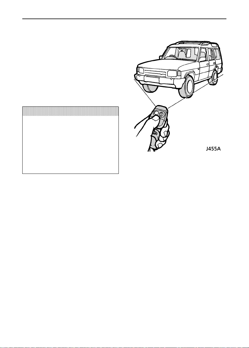
Locking with the handset
Within range of the vehicle briefly press the
lock button (PADLOCK SYMBOL) on the
handset. If the doors lock correctly, the hazard
warning lights will flash three times and the
alarm system indicator (located in the
instrument panel) will start to flash.
Each time the vehicle is locked using the
handset, a coded signal is transmitted to a
receiverinsidethe vehicle, which activates the
following security features:
10
Locks & Alarm
• the central door locking system (all the
door locks are activated).
• the perimetric alarm (protects the doors
and bonnet).
• ultrasonic space protection (protects the
space inside the passenger compartment).
• engine immobilisation.
Once armed, the alarm will sound if any door
is opened, or if (after a checkingperiod of 15
seconds) any movement is detected inside the
passenger compartment (see ’Ultrasonic
space protection’).
If the hazard warning lights fail to flash and
the horn sounds twice when the handset is
used to lock the vehicle, this indicates that
either the bonnet or a door is not fully closed.
In this case the alarm will still be armed and
the engine immobilised, but ultrasonic space
protection will not have been activated.
Once the open door or aperture is closed, the
hazard warning lights will flash three times
and the alarm system will arm itself as
described previously.
Unlocking with the handset
Within range of the vehicle briefly press the
PLAIN button on the handset; the hazard
warning lights flash once, the alarm is
disarmed immediatelyand the engine is
re-mobilised.
If the alarm sounds
To silence the alarm, press either handset
button, or operate the door locks using the
key. If the alarm is not silencedit will sound
for approximately 30 seconds before
switching itself off, and can be triggered up to
three times in total before needing to be reset.
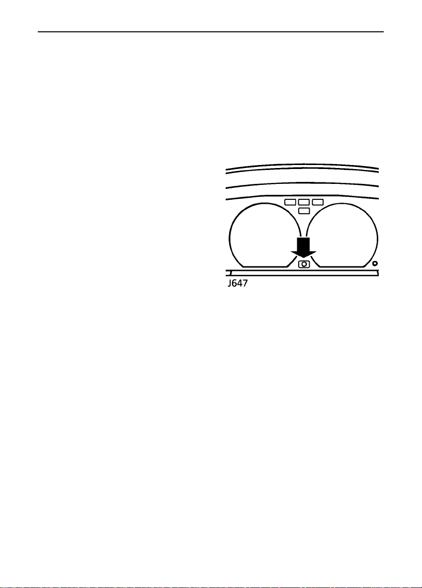
Anti-theft alarm indicator light
After locking, the RED indicator light on the
instrument panel will flash rapidly while the
alarm system is arming itself.
After 10 seconds, the indicator light adjusts to
a slower frequency, and continues flashing as
an anti-theft deterrent until such a time as the
alarm is disarmed.
NOTE: Dependent upon the territory, the
hazard lights will flash once and the interior
light illuminates when the alarm system is
disarmed.
If the handset fails to unlock the vehicle, use
the key and resynchronise the handset (see
item 6 under ’Handset battery’).
11

Locks & Alarm
Ultrasonic space protection
Ultrasonic space protection is only activated
when the alarm is armed using the handset.
Twin sensors monitor the interior space and
activate the alarm if an intrusion into the
passenger compartment is detected (entry
gained through a window or sunroof, for
example).
ENGINE IMMOBILISATION
Engine immobilisation is an important aspect
of the security system, and includes a feature
known as ’passive immobilisation’. This is
designed to safeguard the vehicle from theft
should the driver forget to lock the doors and
ensures that the engine is immobilised
automaticallywheneverany of the following
conditions occur:
- when the vehicle is locked using the handset
or key.
- thirty seconds after the starter switch has
been turned off AND the driver’s door opened.
- five minutes after the starter switch is turned
off, or the alarm system is disarmed.
The engine will be re-mobilised automatically
whenever the key is inserted into the starter
switch, provided the handset is kept on the
key ring in close proximity to the starter
switch.
WARNING
To ensure that the engine is automatically
re-mobilised when the key is inserted into
the starter switch, always keep the handset
on the same keyring as the key.
12

Locks & Alarm
ENGINE IMMOBILISATION OVERRIDE
(Entering the emergency key access code)
If the handset is lost or fails to operate, the
engine can be re-mobilised by using the key to
enter a unique four digit emergency key
access code. The code is recorded on the
Security Information card and is entered as
follows:
1. Using the key, turn the
driver’s door lock to the LOCK
position and hold in this
position for at least 5
seconds. Then return the key
to the centre position (as shown). It is now
possible to use the key to enter the separate
numerical values of the four digits that make
up the emergency key access code.
IMPORTANT INFORMATION
When entering a code:
• ENSURE each key movement is
carried out with care and precision
and turned through the full extent of
its travel.
• After turning the key to either the
lock or unlock positions, make sure
it is FULLY returned to the centre
(vertical)position.
• If a digit is entered incorrectly, the
WHOLE code can be cancelled by
returning to operation ’1’ and
starting again.
2. Enter the FIRST digit of
the code. If the first digit is 4,
turn the key to the UNLOCK
position 4 times. Ensure the
key is FULLY returned to the
centre position after each turn of the key.
3. Enter the SECOND digit of
the code. If the second digit is
3, turn the key to the LOCK
position 3 times. Remember;
the key must be FULLY
returned to the centre position after each turn
of the key.
4. Enter the THIRD digit of
the code. If the third digit is
2, turn the key to the UNLOCK
position twice, ensuring that
the key is FULLY returned to
the centre position after each turn of the key.
5. Enter the FOURTH digit of
the code. If the fourth digit is
1, turn the key to the LOCK
position once. Ensure the key
is FULLY returned to the
centre position after the key has been turned.
6. FINALLY, turn the key to
the UNLOCK position once
more to disarm the alarm and
re-mobilisethe engine. If the
code has been entered
successfully,the anti-theft alarm indicator
light on the instrument panel will extinguish
and the engine can be started.
13

Locks & Alarm
If an incorrect code has been entered:
If the code has been entered incorrectly,the
sounder will bleep twice and the anti-theft
alarm indicator light will continue to flash. In
this case, return to ’1’ and re-enter the code.
After three failed entry attempts, the security
system invokes a delay period of thirty
minutes during which the system will not
accept any further attempts to enter a code.
NOTE: Once the engine immobiliser has been
deactivated by entering the emergency key
access code, it will remain inactive until a
handset is next used to lock the vehicle.
WARNING
• NEVER leave the Security Information
card in the vehicle.
• Memorise the emergency key access
code or keep the Security Information
card on your person in case of
emergencies (a damaged handset for
example).
14
Locks & Alarm
HANDSET BATTERY
The handset battery should last for
approximatelythree yearsdependent upon
use. When the battery needs replacing it will
be apparent from the following symptoms:
• The handset will only work every other
operation.
• The hazard warning lights will not flash on
disarm.
Always fit a Panasonic CR2032 replacement
battery (availablefrom a Land Rover dealer)
and adopt the following replacement
procedure:
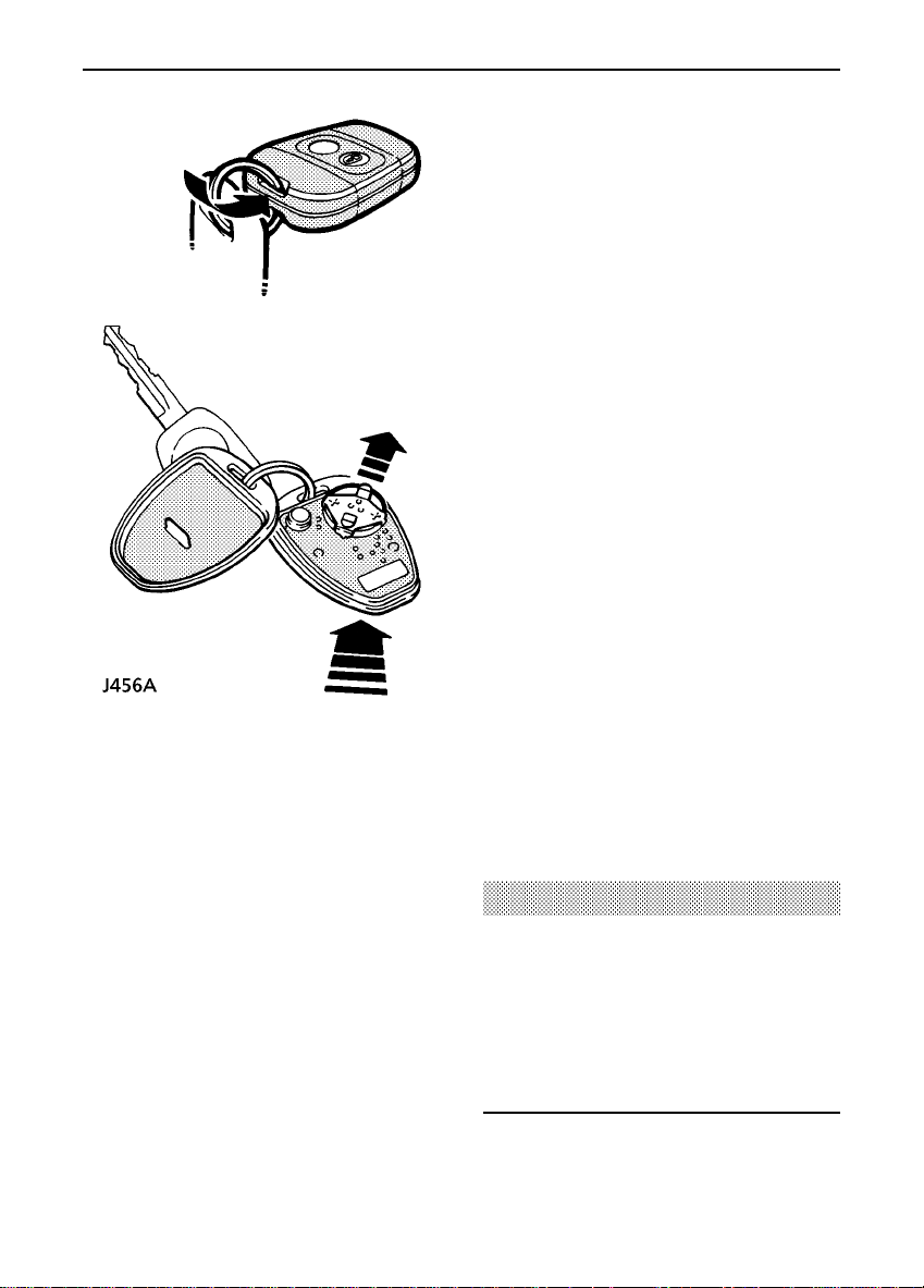
1) Carefully prise the handset apart, start from
the keyring end using a coin or small
screwdriver.Avoid damaging the seal between
the two halves of the case and DO NOT allow
dirt or moisture to get inside the handset.
2) Slide the battery out of its clip, taking care
to avoid touching the circuit board or the
contact surfaces of the clip.
3) Press and hold one of the buttons for at
least five seconds (this will drain any residual
power from the handset).
4) Fit the new battery, ensuring that correct
polarity is maintained (positive (’+’) side
facing up). Finger marks will adversely affect
battery life; if possible, avoid touching the flat
surfaces of the battery and wipe them clean
before fitting.
5) Reassemble the two halves of the handset.
6) Unlock the vehicle using the key, then
operate the lock button of the handset at least
four times.
The handset is now ready for use.
WARNING
The handset contains delicate electronic
circuits and must be protected from:
impact and water damage, high
temperatures and humidity, direct sunlight
and the effects of solvents, waxes and
abrasive cleaners.
15

Locks & Alarm
IMPORTANT INFORMATION
Battery disconnection
Your vehicle is equipped with a battery backed-up sounder, which powers the alarm siren
should the vehicle battery be disconnected.
In some markets, vehicles may be equipped with a battery backed-up sounder, which powers
the alarm siren should the vehicle battery be disconnected.
Before disconnecting the vehicle battery, it is ESSENTIAL to refer to ’Battery removal and
replacement’in Section 4, in order to prevent the alarm from sounding.
If the vehicle battery is disconnected for any reason, the status of the security system prior to
disconnection will be memorised and automatically reset when the battery is reconnected.
ALARM OR HANDSET DIFFICULTIES
Alarm goes off unexpectedly. (a) Ensure all windows and sunroof are closed.
(b) Disable ultrasonic alarm (refer to ’Locking
using the key’).
Alarm goes off when door opened. Unlock vehicle with handset, NOT the door key.
If the handset has failed, enter the emergency
key access code (refer to ’Engine
immobilisation override’).
Vehicle will not start. Pressunlockbutton on handset. If it still will
not start, consult your Land Rover dealer.
Hazard lights don’t flash and horn
sounds twice when alarm is armed.
Doors unlock and hazard lights start to
flash when vehicle is in motion.
Within range of the vehicle the handset
appears to malfunction.
Ensure all doors and bonnet are closed.
The inertia switch has been triggered. Stop the
vehicle and turn the starter switch off and on
again. Central door locking will be inhibited for
5 minutes. If fault continues, consult your Land
Rover dealer.
The handset may have lost synchronisation.
Press the lock button on the handset four times
whilst within range of the vehicle.
16

Locks & Alarm
KEY AND HANDSET NUMBERS
You have been supplied with two identical
remote control handsets and a pair of identical
keys which operate all locks, including the
taildoor and petrol flap.
The key number is stamped on a tag attached
to the key ring. Check that the key number has
been entered in the space provided on your
Security Information card.
If the key or handset is lost, contact a Land
Rover dealer, who can supply replacement or
additional keys and handsets.
WARNING
Keep the Security Information card, key tag,
spare key and handset in a safe place - NOT
IN THE VEHICLE!
Spare wheel locking nut key
In some markets, vehicles fitted with alloy
wheels are equipped with a locking cap which
fits over one of the wheel nuts securing the
spare wheel to the taildoor. In this case, two
additional (smaller)keyswill have been
supplied to lock and unlock the cap (see
’Wheel Changing’). Keep a record of the key
number in a safe place.
Locking using the key
Locking the vehicle with the key instead of the
handset restricts securityprotectionto the
perimetric alarm and engine immobilisation
only. Ultrasonic space protection will not be
activated!
WARNING
The handset MUST be used to unlock the
vehicle. Unlocking the vehicle using the key
does not disarm the alarm or re-mobilise
the vehicle.
Door sill locking buttons
From inside the vehicle, each door can be
individuallylockedby depressing the
appropriate button.
NOTE: When the driver’s door locking button
is operated, the central locking system
operates all door locks simultaneously.
17
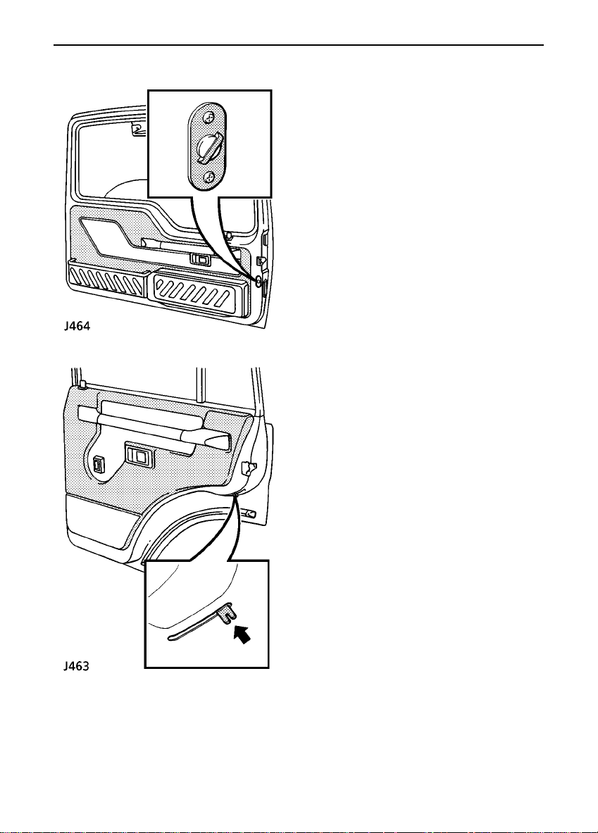
Locks & Alarm
Move the locking levers to the ’ON’ position
(as illustrations)to engage.
With the child-proof locks engaged, neither
the rear doors nor the taildoor can be opened
from inside the vehicle, thereby avoiding the
risk of a door being opened accidentallywhile
the vehicle is moving.
Door locking cut-off switch
An inertia switch, operational only with the
starter switch in position ’II’, prevents the
doors centrally locking (or if the doors are
locked, will unlock them) in the event of an
accident or sudden impact.
When the inertia switch operates, the hazard
warning lamps flash (if market permits).
Central door locking is inhibited and hazards
flash for a minimum of 30 seconds or until the
system is reset by turning the starter switch
on and off.
Child-proof locks
18

Seats
FRONT SEAT ADJUSTMENT
Forward/backward movement
Lift the bar to slide the seat forward or back.
Ensure the seat is locked in position before
driving.
WARNING
To avoid the risk of loss of control. DO NOT
adjust the driver’s seat while the vehicle is
in motion.
DO NOT allow front seat occupants to travel
with the seat backs reclined steeply
rearwards. Optimum benefit is obtained
from the seat belt with the seat back angle
set to 25 degrees from the upright (vertical)
position.
Lumbar support (1)
Rotate the handwheel to increase or decrease
support to the lumbar region of the back.
Backrest movement (2)
Rotate the handwheel to achieve the desired
backrest angle.
19

Seats
FOLDING THE REAR SEATS
WARNING
Tilt movement - (3 door models only)
Lift the lever to release, then tilt the seat
forward. Push the seat back and ensure the
seat is locked in position before driving.
NOTE: On some models the drivers seat is
fixed.
DO NOT adjust the seats while the vehicle is
in motion.
Ensure your fingers are clear of the seat
latches when folding the rear seats.
Before folding the rear seats, pass the seat
belt locks through the junction of the backrest
and the cushion and into the loadspace.
1. Push the release buttons (arrowed in
illustration).
20
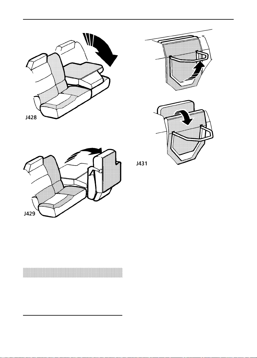
2. Fold the backrest forward.
Seats
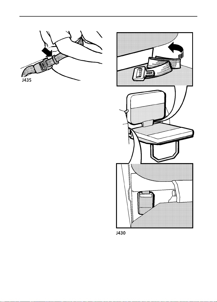
INWARD FACING SEATS
(if fitted)
With the loadspace cover (if fitted) retracted
and secured, pull out the seat stand, and fold
down the seatbase.
3. Lift and fold the base of the seat forwards.
When returning the backrest to the upright
position, ensure it is securely latched in place
before driving.
WARNING
When the seat is erected, the latching
mechanism should be visually checked and
physically tested to ensure that the latch is
secure before driving.
21
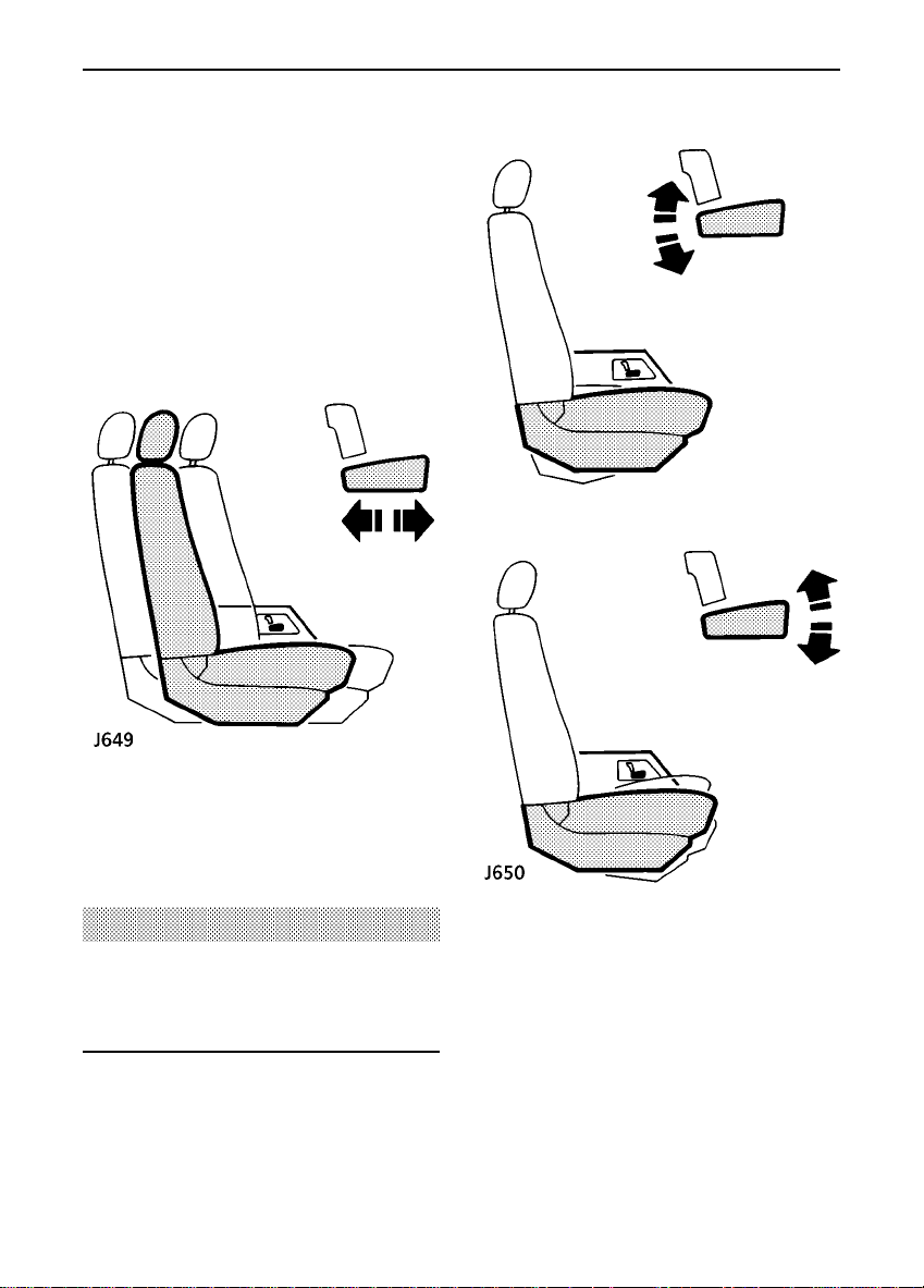
POWER OPERATED FRONT SEATS
(if fitted)
The seat adjustment controls are situated on
the side of the centre console.
Seat adjustment is only possible when the
starter switch is turned to positions ’I’ or ’II’
or with a front door open when the starter
switch is at position ’0’.
The following functions are available:
Seats
Forward/backward movement
Push and hold the switch forwards or
backwards to move the seat to the desired
position.
WARNING
To avoid the risk of loss of control, DO NOT
adjust the driver’s seat while the vehicle is
in motion.
Seat cushion angle
Twist the switch to tilt the front or rear of the
seat cushion to the desired position.
22
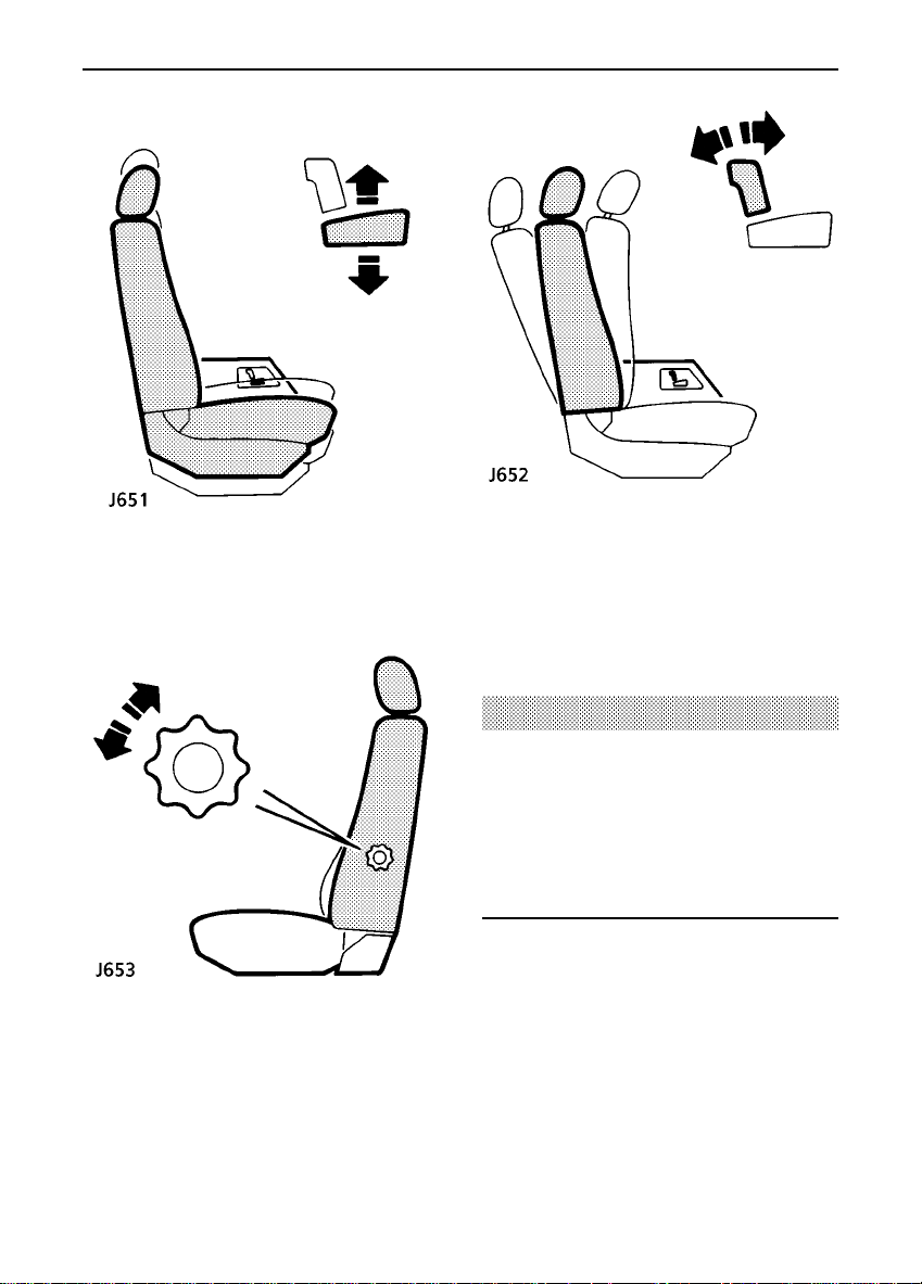
Seats
SEAT CUSHION HEIGHT
Push the switch up or down to raise or lower
the cushion.
Lumbar support adjustment
Rotate the handwheel to increase or decrease
support to the lumbar region of the back.
Seat back adjustment
Twist the switch forward or backward until the
desired seat back angle is achieved.
WARNING
DO NOT allow front seat occupants to travel
with the seat backs reclined steeply
rearwards. Optimum benefit is obtained
from the seat belt with the seat back angle
set to 25 degrees from the upright (vertical)
position.
23
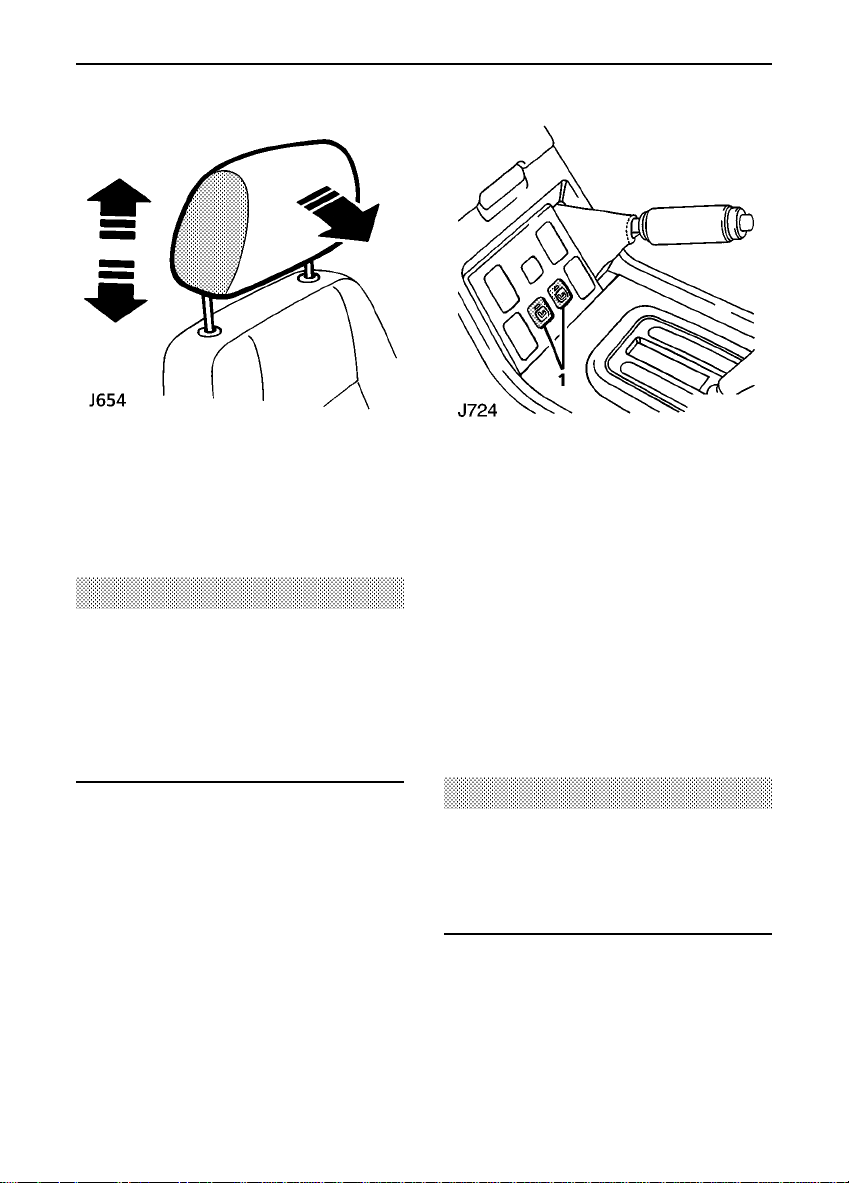
Seats
Head restraint adjustment
Raise or lower the head restraint until it is
level with the back of the head.
WARNING
Head restraints are designed to support the
back of the head (NOT THE NECK), and to
restrain rearward movement of the head in
the event of a collision. The restraint must
be positioned level with the head to be
effective.
Heated front seats
With the starter switch turned to position ’II’,
press one of the switches (No 1 in illustration)
to operate the heating elements in either the
driver’s or front passenger seat (the indicator
light in the switch will illuminate). Press the
switch a second time to switch off.
The seat heaters are thermostatically
controlled and operate intermittently to
achieve and then maintain a predetermined
temperature between 26° and 36° C.
WARNING
The seat heaters consume considerable
power from the battery. For this reason, they
should only be operated when the engine is
running.
24

Seat belts
SEAT BELT SAFETY
Seat belts are life saving equipment.
In a collision unrestrained passengers can be
thrown around inside the vehicle, or possibly
thrown out of the vehicle,resultingin injury to
themselves and to other occupants. DO NOT
take chances with safety!
• DO make sure ALL passengers are
securely strapped in at all times - even for
the shortest journeys.
• ALWAYS adjust seat belts to eliminate any
slack in the webbing. DO NOT slacken the
webbing by holding the belt away from the
body - to be fully effective,the seat belt
must remain in full contact with the body
at all times.
• ALWAYS fit the lap strap as low on the
hips as possible (never across the
abdomen), and ensure that the diagonal
belt passes across the shoulder without
slipping off or pressing on the neck.
• DO have seat belts checked if the vehicle is
involved in an accident.
• DO NOT allow a baby or infant to be
carried on the lap. The force of a crash can
increase effectivebody weight by as much
as 30 times, making it impossible to hold
on to the child.
• DO use the seat belts to secure large items
of luggage that are to be carried on the
seats - in the event of an accident,
insecure items become flying missiles
capable of causing serious injury.
• DO NOT fit more than one person into a
belt, or use a seat belt that is twisted or
obstructed in any way that could impede
its smooth operation.
• DO NOT allow front seat occupants to
travel with the seat backs reclined steeply
rearwards. Optimum benefit is obtained
from the seat belt with the seat back angle
set to 25 degrees from the upright
(vertical)position.
• DO NOT allow foreign matter (particularly
sugary food and drink particles) to enter
the seat belt locks - such substances can
render the locks inoperative.
• Pregnant women should ask a doctor for
advice about the safest way to wear seat
belts.
WARNING
The airbag supplementary restraint system
(SRS) is designed to add to the overall
effectiveness of the seat belts. It DOES NOT
replace them. SEAT BELTS MUST ALWAYS
BE WORN!
Ensure that all seat belts are worn correctly
- an improperly worn seat belt increases the
risk of death or serious injury in the event of
a collision.
25
Seat belts
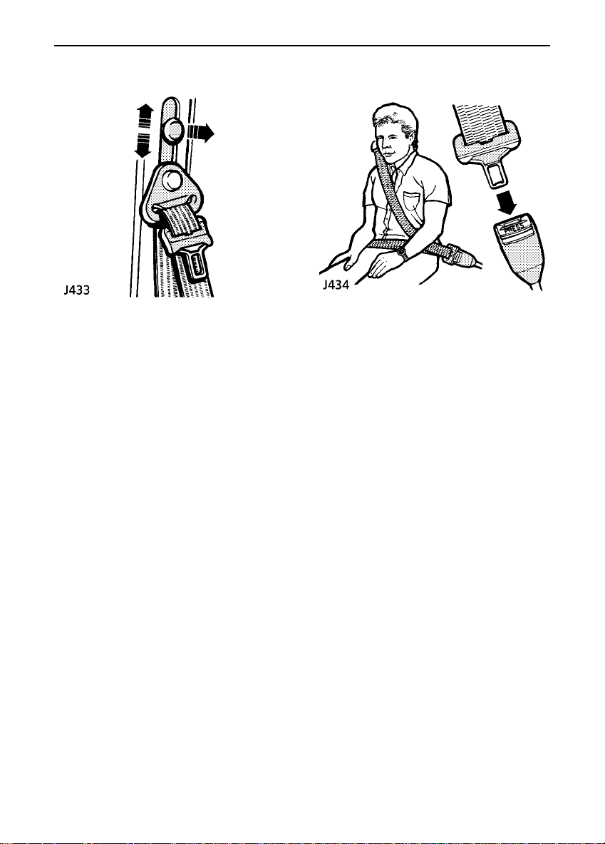
Upper anchorage adjustment (front seats)
(5 door models)
The height of the seat belt upper anchorage
can be adjusted for comfort AND safety. Pull
the button out to raise or lower. For safety, the
seat belt should always be worn with the
webbing crossing the shoulder MIDWAY
BETWEEN THE NECK AND THE EDGE OF THE
SHOULDER.
Ensure the anchorage has ’clicked’ into one of
the locked positions before driving.
Fastening the inertia reel belts
Draw the belt over the shoulder and across
the chest, and insert the metal tongue plate
into the lock nearest the wearer - a ’CLICK’
indicates that the belt is securely locked.
Seat belts are designed to bear upon the bony
structure of the body (pelvis, chest and
shoulders) and can only be worn safely with
the seats in a normal upright position - DO
NOT allow the front passenger to travel with
the seat steeply reclined.
26
Seat belts
Lap belts
The rear central and inward facing seating
positions are fitted with lap belts only. To
adjust, pull the slider along the belt and feed
the webbing through the buckle until the belt
is comfortably tight.
Inward facing seat belt stowage:
Fold the seat belt as shown and tuck into the
pocket at the base of the backrest.
Push the seat belt lock onto the clip where
shown.
27

Seat belts
Child seats
The seat belts fitted to your vehicle are
designed for adults and larger children. For
safety, it is very important that infants and
young children are restrained in a suitable
child seat. For further information on child
seats availablefor your vehicle, please contact
your Land Rover dealer.
Only fit a child seat that has been approved for
use in your vehicle, and ensure the
manufacturer’sfitting instructionsare
followed exactly.
Vehicles fitted with a passenger airbag:
It is not recommended that a child safety seat
is fitted to the front passengerseat if the
vehicle is equipped with a passenger airbag
system. If it is essential for a child to travel in
the front (i.e. in an emergency), set the seat
fully rearward and use ONLY an approved
FORWARD FACING child restraint.
WARNING
DO NOT install a rear facing child seat in the
front passenger seat if a passenger airbag is
fitted.
NEVER leave a child unattended in the
vehicle.
The above symbol affixed to the fascia panel
of your vehicle, warns against the use of a
rear facing child seat in the front passenger
seat, when a passenger airbag is fitted. This
type of child seat could cause serious injury to
your child in the event of an airbag
deployment.
28

Seat belts
Caring for seat belts
Regularly inspect the belt webbing for signs of
fraying, cuts and wear; also pay particular
attention to the condition of the fixing points
and adjusters.
DO NOT bleach or dye the webbing. Clean
using ONLY warm water and non-detergent
soap - allow to dry naturally and do not retract
or use the belts until they are completelydry.
Testing inertia reel belts
1. With the seat belt fastened, give the
webbing near the buckle a quick upward
pull. The buckle must remain securely
locked.
2. With the seat belt unfastened, unreel the
webbing to the limit of its travel. Check
that unreeling is free from snatches and
snags.
3. With the webbing half unreeled, hold the
tongue plate and give it a quick forward
pull. The mechanism must lock
automaticallyand prevent any further
unreeling.
If a seat belt should fail any of these tests,
contact your dealer immediately.
WARNING
Always replace a seat belt that shows signs
of webbing damage or has withstood the
strain of a severe vehicle impact.
29
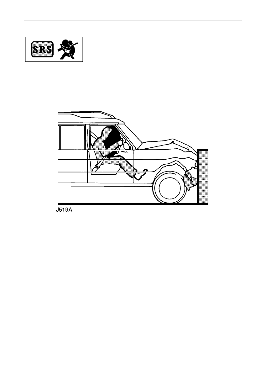
Airbag SRS
The airbag supplementary restraint system (SRS) (when fitted)
provides additional protection for either the driver, or the driver
and front seat passenger, in the event of a severe frontal impact on
the vehicle.
Always remember; the airbag is a supplementary restraint system that provides ADDITIONAL
protection in a frontal impact only - it does NOT replace the need to wear a seat belt. For
maximum safety protection in all crash situations, a seat belt must be worn.
30

Airbag SRS
How the airbag SRS works
The airbag supplementary restraint system
(SRS) includes either: a single airbag module
(mounted in the steering wheel centre pad) for
the driver, or twin airbag modules (where
shown in illustration) to protect both the
driver and the front seat passenger.
In the event of a collision involvinga frontal
impact, the airbag control unit monitors the
decelerationcausedby the impact to
determine whether the airbag SRS should be
activated.
If the impact is sufficiently severe, the system
causes each airbag to inflate. Inflation is
instantaneous and accompanied by a loud
noise. Also evident may be traces of smoke
and powder, neither of which are injurious or
indicative of a malfunction of the airbag.
After inflation, the driver’s airbag will
immediately deflate, thereby ensuring that
visibilityis not impaired.
NOTE: An airbag will not inflate as a result of
heavy braking, minor bumps or potholes.
WARNING
Following inflation some airbag SRS
components are hot - DO NOT touch until
they have cooled.
31
 Loading...