

Page 1

Baffle Kit Assembly Instructions and
Shredder Kit Assembl y Instructions
RC(M)5015/6015 with Comer Gearboxes (S/N 325493+)
Before You Start
When you see this symbol, the subsequent
instructions and warnings are serious - follow
!
without exception. Your life and the lives of
others depend on it!
IMPORTANT: Before you begin, read these
instructions and check to be sure all par ts and tools
are accounted for. Please retain these installation
instructions for future reference and parts ordering
information.
Your Baffle/Shredder Kit for Comer Gearbox (S/N
325493+) is exclusively designed for your Land Pride
RC5015 Rotary Cutter. Please read these installation
instructions and your RC5015 Rotary Cutter Operator’s
Manual thoroughly before beginning. Especially read
information relating to safety concerns. Also included in
the Operator’s Manual is important information on
operation, adjustment, troubleshooting, and
maintenance forthis attachment (some manual sections
do not apply to all accessories).
General Information
These assembly instructions apply to the following
RC5015 Baffle/Shredder Kit Accessories listed below:
318-395A ASSY.BAFFLE/SHRD COMER RC50-60
Further Assistance
Your dealer wants you to be satisfied with your new
Baffle/Shredder Kit for Comer Gearbox (S/N 325493+).
If for any reason you do not understand any part of this
manual or are not satisfiedwith the service received, the
following actions are suggested:
1. Discuss the matter with your dealership service
manager making sure he is aware of any problems
youmay haveand that he has had the opportunity to
assist you.
2. If you are still not satisfied, seek out the owner or
general manager of the dealership, explain the
problem and request assistance.
3. For further assistance write to:
Assembly Instructions
Adetailedlistingof parts for this accessory kit is provided
on page 4. Use the list as a checklist to inventory parts
received.Please contact yourlocalLand Pride dealerfor
any missing hardware.
!
Lower implement to the ground, put tractor in park, turn off
engine, engage parking brake, and remove key before
performing installation of the Baffle/Shredder Kit.
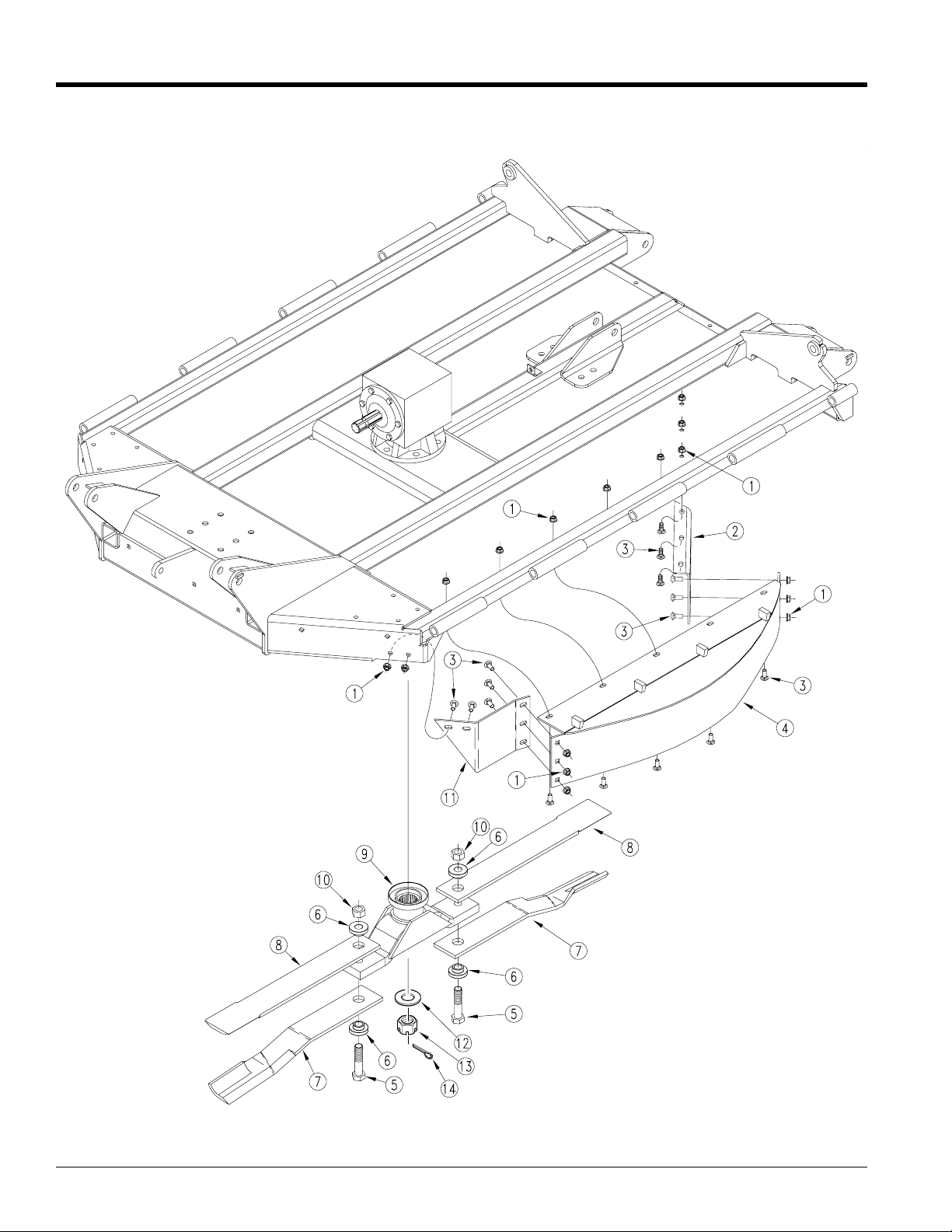
Baffle/Shredder Installation
Refer to Figure 2 on page 3:
1. Before the Baffle/Shredder Kit can be installed,
Refer to Figure 1 on page 2:
2. Assemble Front Mounting Plate (#11) and Rear
3. Mount this assembly in the holes that were drilled in
4. Removeblade carrierassemblyfrom gearbox output
5. Install Blade carrier (#9) to gearbox output shaft.
6. Assemble blades (#7) and (#8) to the blade carrier
7. Repeat steps 3, 4 and 5 for Right Hand and Left
CAUTION
eight - 17/32" dia. holes must be drilled in the center
deck. Refer to page 3 for hole locations.
Mounting Plate (#2) to Center Baffle (#4) with
carriage bolts (#3) and flange nuts (#1) as shown.
the center deck using carriage bolts (#3) and flange
nuts (#1).
shaft. Keep the hardened washer (#12) slotted hex
nut (#13) and cotter pin (#14) to use in step #4.
Installing blade carrier without the blades attached
will be much easier. Reinstall washer (#12) and nut
(#13). The slotted nut should be torqued to 550 ft./
lbs.Thecotter pin (#14) shouldbeinstalled in the nut
with legs securely bent around the nut.
(#9). Torque blade bolt lock nut (#10) to 450 ft./lbs.
Hand Deck.
Manual No. 318-314M
Land Pride Service Department
1525 East North Street
Salina, Ks. 67402-5060
lpservicedept@landpride.com
© Copyright 2007 Printed
P.O. Box 5060
E-mail address
07/02/07
1
Page 2
Assembly Instructions
Land Pride
Figure 1
Manual No. 318-314M 07/02/07
2
■
Page 3

Assembly Instructions
NOTE: Horizontal dimensions are referenced from
side of hinge tube.
Verticaldimensions are referencedfromfront side of
hydraulic cylinder lug.
Land Pride
07/02/07
Hole Location
Figure 2
■
Manual No. 318-314M
3
Page 4

Land Pride
Listing of Parts
Kit No. 318-395A ASSY.BAFFLE/SHRD COMER RC50-60
Item Qty. Part No. Part Description
1 16 803-037C NUT HEX WHIZ 1/2-13 PLT
2 1 318-308D BAFFLE REAR MOUNTING PLATE LH.
3 16 802-214C RHSNB 1/2-13X1 1/4 GR5
4 1 318-303H WELDMENT CENTER BAFFLE LH.
5 6 802-680C HHCS 1-8 X 4 1/2 PLT GR8
6 12 318-309D BLADE BUSHING
7 2 820-168C CUTTER BLADE 1/2X4X29 CCW. . . . . . . . . . . . . . . . . . . . . Center Deck Shown
8 2 820-216C CUTTER BLADE 1/2X4X28.5 FLAT . . . . . . . . . . . . . . . . . . . Center Deck Shown
9 3 318-396H WELDMENT BLADE CARRIER COMER
10 6 803-168C NUT HEX TOP LOCK 1-8 PLT
11 1 318-346D BAFFLE FRT. MOUNTING PLATE LH.
2 820-169C CUTTER BLADE 1/2X4X23 CCW. . . . . . . . . . . . . . . . . . . . . RH Wing Not Shown
2 820-170C CUTTER BLADE 1/2X4X23 CW . . . . . . . . . . . . . . . . . . . . . . LH Wing Not Shown
4 820-217C CUTTER BLADE 1/2X4X22.5 FLAT . . . . . . . . . . . . . .LH & RH Wings Not Shown
4
Manual No. 318-314M 07/02/07
■
 Loading...