

Landoll PT User Manual

®
Transport Pulverizer
Operator’s Manual
P Series 10’ through 16’
PT Series 10’ through 20’
LANDOLL CORPORATION
1900 North Street
Marysville, Kansas 66508
(785) 562-5381
800-428-5655 ~ WWW.LANDOLL.COM
189rev0713 9J017


1 Introduction and Safety Information
Introduction . . . . . . . . . . . . . . . . . . . . . . . . . . . . . . . . . . . . . . . . . . . . . . . . . . . . . . . . . . . . . . . . . . 1-1
Description of Unit . . . . . . . . . . . . . . . . . . . . . . . . . . . . . . . . . . . . . . . . . . . . . . . . . . . . . . . . . 1-1
Using this Manual . . . . . . . . . . . . . . . . . . . . . . . . . . . . . . . . . . . . . . . . . . . . . . . . . . . . . . . . . 1-1
Owner Assistance . . . . . . . . . . . . . . . . . . . . . . . . . . . . . . . . . . . . . . . . . . . . . . . . . . . . . . . . .1-1
Warranty Registration . . . . . . . . . . . . . . . . . . . . . . . . . . . . . . . . . . . . . . . . . . . . . . . . . . . . . .1-1
Understanding Safety Statements . . . . . . . . . . . . . . . . . . . . . . . . . . . . . . . . . . . . . . . . . . . . . 1-2
Transporting Safety . . . . . . . . . . . . . . . . . . . . . . . . . . . . . . . . . . . . . . . . . . . . . . . . . . . . . . . . 1-2
Attaching, Detaching and Storage . . . . . . . . . . . . . . . . . . . . . . . . . . . . . . . . . . . . . . . . . . . . . 1-2
Maintenance Safety . . . . . . . . . . . . . . . . . . . . . . . . . . . . . . . . . . . . . . . . . . . . . . . . . . . . . . . .1-3
Protective Equipment . . . . . . . . . . . . . . . . . . . . . . . . . . . . . . . . . . . . . . . . . . . . . . . . . . . . . .1-3
Chemical Safety . . . . . . . . . . . . . . . . . . . . . . . . . . . . . . . . . . . . . . . . . . . . . . . . . . . . . . . . . . 1-3
High Pressure Fluid Safety . . . . . . . . . . . . . . . . . . . . . . . . . . . . . . . . . . . . . . . . . . . . . . . . . . 1-3
Prepare for Emergencies . . . . . . . . . . . . . . . . . . . . . . . . . . . . . . . . . . . . . . . . . . . . . . . . . . . 1-3
Tire Safety . . . . . . . . . . . . . . . . . . . . . . . . . . . . . . . . . . . . . . . . . . . . . . . . . . . . . . . . . . . . . . . 1-3
Safety Chain . . . . . . . . . . . . . . . . . . . . . . . . . . . . . . . . . . . . . . . . . . . . . . . . . . . . . . . . . . . . . 1-3
Table of Contents
2 Assembly
Transport Pulverizer Assembly . . . . . . . . . . . . . . . . . . . . . . . . . . . . . . . . . . . . . . . . . . . . . . . . . . 2-1
Frame Assembly . . . . . . . . . . . . . . . . . . . . . . . . . . . . . . . . . . . . . . . . . . . . . . . . . . . . . . . . . .2-1
End Brackets Installation: . . . . . . . . . . . . . . . . . . . . . . . . . . . . . . . . . . . . . . . . . . . . . . . . . . .2-3
Wheel And Axle Assemblies (Wheel Gangs) Installation . . . . . . . . . . . . . . . . . . . . . . . . . . . 2-4
Drawbar Hitch Installation . . . . . . . . . . . . . . . . . . . . . . . . . . . . . . . . . . . . . . . . . . . . . . . . . . . 2-7
Drawbar Brace Installation . . . . . . . . . . . . . . . . . . . . . . . . . . . . . . . . . . . . . . . . . . . . . . . . . . 2-8
Wheel Arms to Center Frame Installation . . . . . . . . . . . . . . . . . . . . . . . . . . . . . . . . . . . . . . . 2-9
Hydraulic Cylinder Installation . . . . . . . . . . . . . . . . . . . . . . . . . . . . . . . . . . . . . . . . . . . . . . . 2-10
Hydraulic Hose Installation: . . . . . . . . . . . . . . . . . . . . . . . . . . . . . . . . . . . . . . . . . . . . . . . . . 2-11
Tightening Procedure For JIC Swivel Female Nuts . . . . . . . . . . . . . . . . . . . . . . . . . . . . . . 2-11
Tightening Procedure For Swivel O-ring Fittings . . . . . . . . . . . . . . . . . . . . . . . . . . . . . . . . . 2-11
PT Series 10’-20’ Models LED Lamp and Harness Installation . . . . . . . . . . . . . . . . . . . . . . 2-12
P Series10’-16’ Models LED Lamp and Harness Installation . . . . . . . . . . . . . . . . . . . . . . . 2-19
Scraper Assembly Procedure for the Optional 8J001 Wheel . . . . . . . . . . . . . . . . . . . . . . . 2-22
Scraper Assembly Procedure for the Optional 3J619 and 8C988 Wheels . . . . . . . . . . . . . 2-23
3 Operation
Operation of the Transport Pulverizer . . . . . . . . . . . . . . . . . . . . . . . . . . . . . . . . . . . . . . . . . . . . . 3-1
Field Operation . . . . . . . . . . . . . . . . . . . . . . . . . . . . . . . . . . . . . . . . . . . . . . . . . . . . . . . . . . . 3-1
Transporting . . . . . . . . . . . . . . . . . . . . . . . . . . . . . . . . . . . . . . . . . . . . . . . . . . . . . . . . . . . . . 3-1
Parking the Transport Pulverizer . . . . . . . . . . . . . . . . . . . . . . . . . . . . . . . . . . . . . . . . . . . . . . 3-2
i

4 Preventative Maintenance
Fasteners . . . . . . . . . . . . . . . . . . . . . . . . . . . . . . . . . . . . . . . . . . . . . . . . . . . . . . . . . . . . . . . . 4-1
Tires . . . . . . . . . . . . . . . . . . . . . . . . . . . . . . . . . . . . . . . . . . . . . . . . . . . . . . . . . . . . . . . . . . . . 4-2
Lubrication . . . . . . . . . . . . . . . . . . . . . . . . . . . . . . . . . . . . . . . . . . . . . . . . . . . . . . . . . . . . . . . 4-2
5 General Reference and Specifications
ii
Chapter 1
DANGER
Introduction and Safety Information
Introduction
The implement described in this manual has been
designed with care and built by skilled workers using
quality materials and processes. Proper assembly and
maintenance will provide you with satisfactory use for
seasons to come.
Read this entire manual before attempting to
assemble, adjust or operate this implement.
Failure to comply with this warning can result in
personal injury or death, damage
implement or its components and inferior
operation.
Description of Unit
The Brillion Transport Pulverizer is designed with the
versatility to operate under a wide variety of soil
conditions. Brillion’s unique transport concept
hydraulically rotates the machine weight over the wheels
for transport. This reduces drawbar hitch weight
considerably and provides ample clearance for
transporting.
to the
Owner Assistance
If customer service or repairs are needed, contact your
Brillion dealer. They have trained personnel, parts and
service equipment specially designed for Brillion
products. Your implement’s parts should only be replaced
with Brillion parts. If items covered in this manual are not
understood, contact your local Brillion Dealer.
Warranty Registration
Brillion Farm Equipment, by Landoll, shall have no
warranty obligation unless each product is registered,
within 10 days of retail purchase, using the Landoll
Corporation Ag Products on-line registration process.
Please refer to the Ag Products Policy and Procedures
Manual, accessible at www.landoll.com
instructions regarding product registration.
Enter your product information below for quick reference.
MODEL NUMBER
SERIAL NUMBER
for step by step
Using this Manual
This manual will familiarize you with safety, assembly,
operation, adjustment, and maintenance. Read this
manual and follow the recommendations to help ensure
safe and efficient operation.
• The information in this manual is current at time of
printing. Some parts may have changed to assure top
performance.
• Location reference: Right and Left designations in this
manual are determined by facing the direction the
implement will travel during field operation, unless
otherwise stated.
DATE OF PURCHASE
Refer to the ID plate as shown. See Figure 1-1.
Figure 1-1: ID Plate
1-1

INTRODUCTION AND SAFETY INFORMATION
NOTE
NOTICE
CAUTION
WARNING
DANGER
NOTE
DANGER
IMPORTANT
Investigation has shown that nearly 1/3 of all farm
accidents are caused by careless use of machinery.
Insist that all people working with you or for you abide by
all safety instructions.
When applying decals to the implement, be sure to clean
the surface to remove any dirt or residue. Where
possible, sign placement should protect the sign from
abrasion, damage, or obstruction from mud, dirt, oil etc.
Understanding Safety Statements
You will find various types of safety information on the
following pages and on the implement decals (signs)
attached to the implement. This section explains their
meaning.
Special notice - read and thoroughly understand.
Proceed with caution. Failure to heed caution
may
cause injury to person or damage product.
Proceed with caution. Failure to heed warning will
cause injury to person or damage product.
Proceed with extreme caution. Failure to heed
notice will cause injury or death to person and/or
damage product.
You should read and understand the information
contained in this manual and on the implement decals
before you attempt to operate or maintain this equipment.
Examine safety decals and be sure you have the correct
safety decals for the implement.
Order replacement decals through your Brillion dealer.
Keep these signs clean so they can be observed readily.
It is important to keep these decals cleaned more
frequently than the implement. Wash with soap and water
or a cleaning solution as required.
Replace decals that become damaged or lost. Also, be
sure that any new implement components installed
during repair include decals which are assigned to them
by the manufacturer.
• Do not allow anyone to ride on the tractor or
implement. Riders could be struck by foreign
objects or thrown from the implement.
• Never allow children to operate equipment.
• Keep bystanders away from implement during
operation.
Tran sporting Safety
It is the responsibility of the owner/operator to
comply with all state and local laws.
When transporting the implement on a road or highway,
use adequate warning symbols, reflectors, lights and
slow moving vehicle sign as required. Slow moving
tractors and towed implements can create a hazard when
driven on public roads. They are difficult to see,
especially at night.
Do not tow an implement that, when fully loaded, weighs
more than 1.5 times the weight of the towing vehicle.
Carry reflectors or flags to mark the tractor and
implement in case of breakdown on the road.
Do not transport at speeds over 20 MPH under good
conditions. Never travel at a speed which does not allow
adequate control of steering and stopping. Reduce
speed if towed load is not equipped with brakes
Avoid sudden stops or turns because the weight of the
implement may cause the operator to lose control of the
tractor. Use a tractor heavier than the implement.
Use caution when towing behind articulated steering
tractors; fast or sharp turns may cause the implement to
shift sideways.
Keep clear of overhead power lines and other
obstructions when transporting. Know the transport
height and width of your implement. See “General
Reference and Specifications” on page 5-1.
Attaching, Detaching and Storage
• Do not stand between the tractor and implement when
attaching or detaching implement unless both are not
moving.
• Block implement so it will not roll when unhitched from
the tractor.
1-2 9J017
INTRODUCTION AND SAFETY INFORMATION
Maintenance Safety
• Block the implement so it will not roll when working on
or under it to prevent injury.
• Do not make adjustments or lubricate the machine
while it is in motion.
• Make sure all moving parts have stopped.
• Understand the procedure before doing the work. Use
proper tools and equipment.
Protective Equipment
• Wear protective clothing & equipment appropriate for
the job. Avoid loose fitting clothing.
• Because prolonged exposure to loud noise can cause
hearing impairment or hearing loss, wear suitable
hearing protection, such as earmuffs or earplugs.
Chemical Safety
• Agricultural chemicals can be dangerous. Improper
use can seriously injure persons, animals, plants, soil
and property.
• Read chemical manufacture’s instructions and store or
dispose of unused chemicals as specified. Handle
chemicals with care and avoid inhaling smoke from
any type of chemical fire.
• Store or dispose of unused chemicals as specified by
the chemical manufacturer.
When inflating tires, use a clip-on chuck and extension
hose long enough to allow you to stand to one side, not in
front of or over the tire assembly. Use a safety cage if
available.
When removing and installing wheels use
wheel-handling equipment adequate for the weight
involved.
Safety Chain
Use the safety chain to help control drawn machinery
should it separate from the tractor drawbar.
Use a chain with a strength rating equal to or greater than
the gross weight of towed machinery, which is 11,000
pounds minimum in accordance with ASAE S338.2
specifications. If two or more implements are pulled in
tandem, a larger chain may be required. Chain capacity
must be greater than the TOTAL weight of all towed
implements.
A second chain should be used between each
implement.
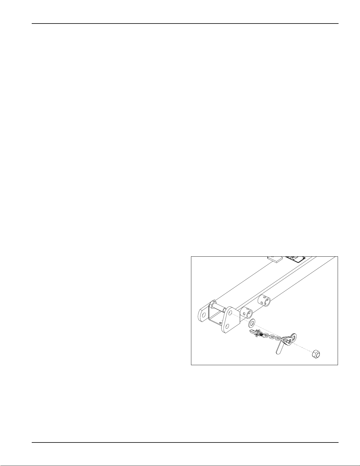
Attach the chain to the tractor drawbar support or
specified anchor location. Allow only enough slack in the
chain to permit turning. The distance from hitch pin to
attachment point or intermediate support point should not
exceed 9 inches. See Figure 1-2.
Replace the chain if any links or end fittings are broken,
stretched or damaged.
Do not use a safety chain for towing.
High Pressure Fluid Safety
Escaping fluid under pressure can be nearly invisible and
have enough force to penetrate the skin causing serious
injury. Use a piece of cardboard, rather than hands, to
search for suspected leaks.
Any fluid injected into the skin must be surgically
removed within a few hours or gangrene may result.
Avoid the hazard by relieving pressure before
disconnecting hydraulic lines.
Prepare for Emergencies
• Keep a First Aid Kit and Fire Extinguisher handy
• Keep emergency numbers for the doctor, ambulance,
hospital and fire department near the phone.
Tire Safety
Tire changing can be dangerous and should be
performed by trained personnel using correct tools and
equipment.
Figure 1-2 Safety Chain
1-3

INTRODUCTION AND SAFETY INFORMATION
WARNING
DO NOT GO NEAR LEAKS
High pressure oil easily punctures
skin causing serious injury,
gangrene or death.
If injured, seek emergency medical
help. Immediate surgery is
required to remove oil.
Do not use fingers or skin to
check for leaks.
Lower load or relieve hydraulic
pressure before loosening fittings.
CAUTION
MOVING MACHINES CAN CAUSE INJURY. KEEP AWAY!
1. KEEP AWAY FROM MOVING TRACTORS OR IMPLEMENTS.
KEEP OTHERS AWAY.
2. DO NOT RIDE OR ALLOW OTHERS TO RIDE ON TRACTOR
OR IMPLEMENT.
3. BLOCK IMPLEMENT TO PREVENT MOVEMENT WHEN
UNHITCHED FROM TRACTOR.
4. KEEP ALL GUARDS AND SHIELDS IN PLACE WHILE
MACHINE OR PARTS ARE IN MOTION.
8J309
THIS MACHINE PRODUCED
UNDER ONE OR MORE OF
THE FOLLOWING PATENTS:
US 3,070,084 US 3,390,727
US 3,555,797 US 4,534,416
US 4,871,030
CANADA 1,223,476
8D387
8D387
R
6K657
4K103
6K657
8J309
3K706
528933
528934
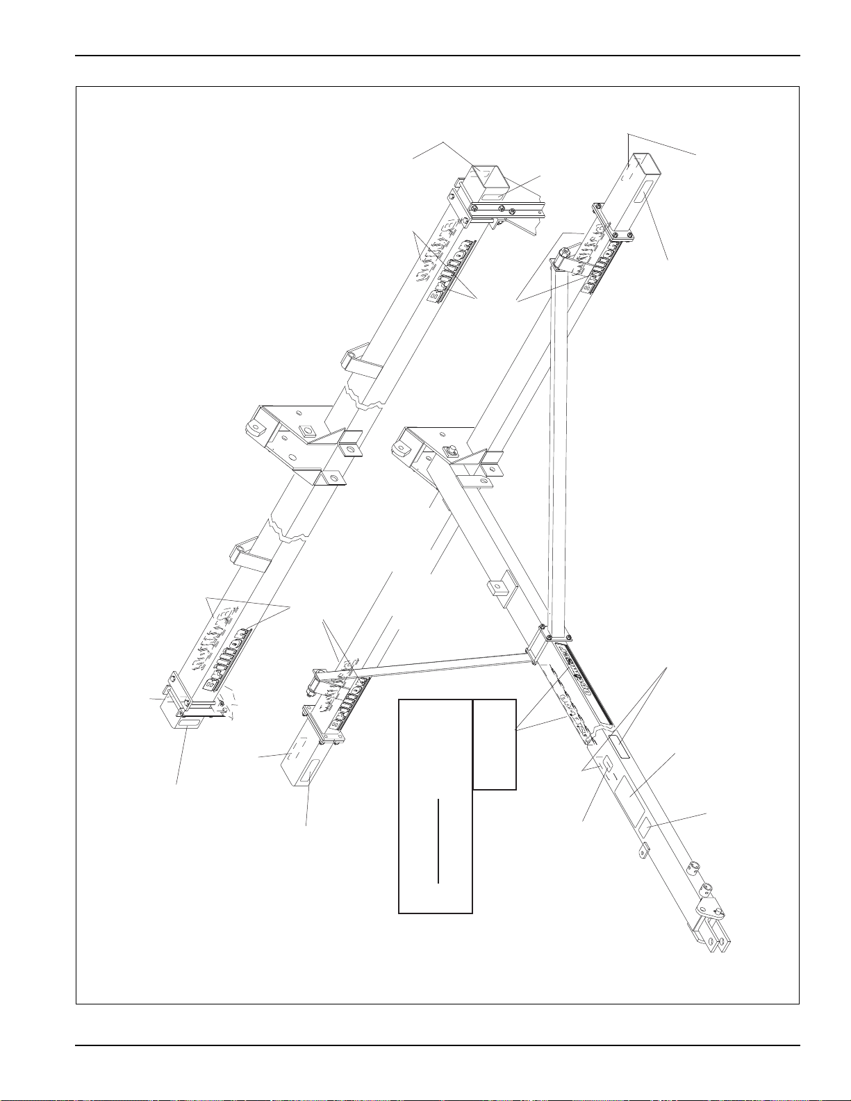
Figure 1-3: Safety Decals
1-4 9J017
4K103
“BRILLION”
(FRONT & BACK)
4K103
“BRILLION”
(FRONT & BACK)
3K706
528933
REFLECTIVE
RED
528934
REFLECTIVE
AMBER
528934
REFLECTIVE
AMBER
528934
REFLECTIVE AMBER
8J309
“CAUTION” LIST
8D387
PATENT
FRAME OF 18- &
20-FT. MODELS
528933
REFLECTIVE RED
10- THROUGH 16-FT.
MODELS
528933
REFLECTIVE RED
528934
REFLECTIVE
AMBER
528933
REFLECTIVE
RED
528934
REFLECTIVE
AMBER
ADDITIONAL DECAL ON
OPTIMIZER MODEL
PULVERIZERS ONLY:
6K657
OPTIMIZER
(BOTH SIDES)
WARNING
HYDRAULIC LEAKS
INTRODUCTION AND SAFETY INFORMATION
Figure 1-4: Safety Decal Locations
1-5

INTRODUCTION AND SAFETY INFORMATION
Page Intentionally Blank
1-6 9J017
Chapter 2
CAUTION
IMPORTANT
NOTE
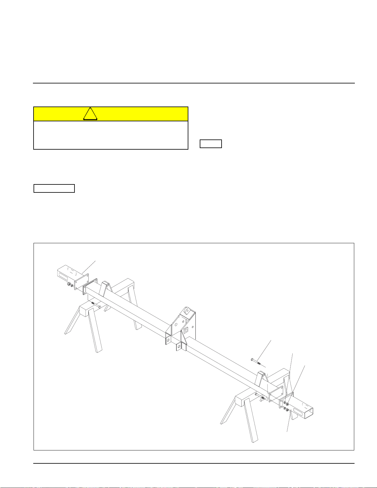
4” x 6” FRAME
FRAME
EXTENSION
FRAME
EXTENSION
SCREW, 5/8” x 2”
LOCKWASHER, 5/8”
NUT, 5/8”
Assembly
Transport Pulverizer Assembly
Do not work on or under this machine unless
securely blocked and supported by a hoist or
tractor or by other sufficient means!
The intent of this chapter is to provide instruction,
allowing you to safely and correctly assemble your
Brillion product.
If a pre-assembled component or fastener is
temporarily removed, ensure it is correctly
re-installed per these instructions.
• Check that all working parts move freely, bolts are
tight and cotter pins are spread.
Frame Assembly
“Left” and “Right” refer to directions seen as if standing
behind the machine and facing in the direction of forward
travel.
1. Place frame section on supports approximately 2' off
the floor. See Figure 2-1.
2. If machine is 12' to 16' in width, bolt center frame
extensions to the ends of the center frame. Use
Grade 5, 5/8-11 x 2" Screws with 5/8" Lockwashers
and Nuts. The 18' and 20’ models utilize a “one
piece” frame and no extensions are required.
Figure 2-1: Frame Assembly
2-1
ASSEMBLY
(This center bracket configuration
is supplied on some models.)
OR
CENTER
BRACKET
SMV BRACKET
SCREW, 1/2” x 1 3/4”
SCREW, 1/2” x 1 1/2”
LOCKWASHER, 1/2”
NUT, 1/2”
NUT, 5/8”
LOCKWASHER, 5/8”
U-BOLT, 5/8”
MACHINE BOLTS, 5/8”
STRAP
SCREW, 1/2” x 2 1/4”
LOCKWASHER, 1/2”
NUT, 1/2”
BEARING ASSEMBLY
3. If a center bracket is included with the machine, it
must be installed next. Start by clamping the center
brackets between the pair of angle iron clips. Use
Grade 5, 1/2" x 1-3/4" Screws with 1/2" Lockwashers
and Nuts. See Figure 2-2.
4. Place the center bracket at the center of the center
frame. Fasten it using 5/8" x 5-1/2" deep U-bolts or,
on 18' and 20’ machines, a pair of straps and 5/8" x
8" Machine Bolts.
5. Attach the SMV Bracket to the Center Bracket U-bolt
and secure with 5/8-11 Hex Nuts and Washers.
Figure 2-2: Center Bracket Assembly
2-2 9J017
ASSEMBLY
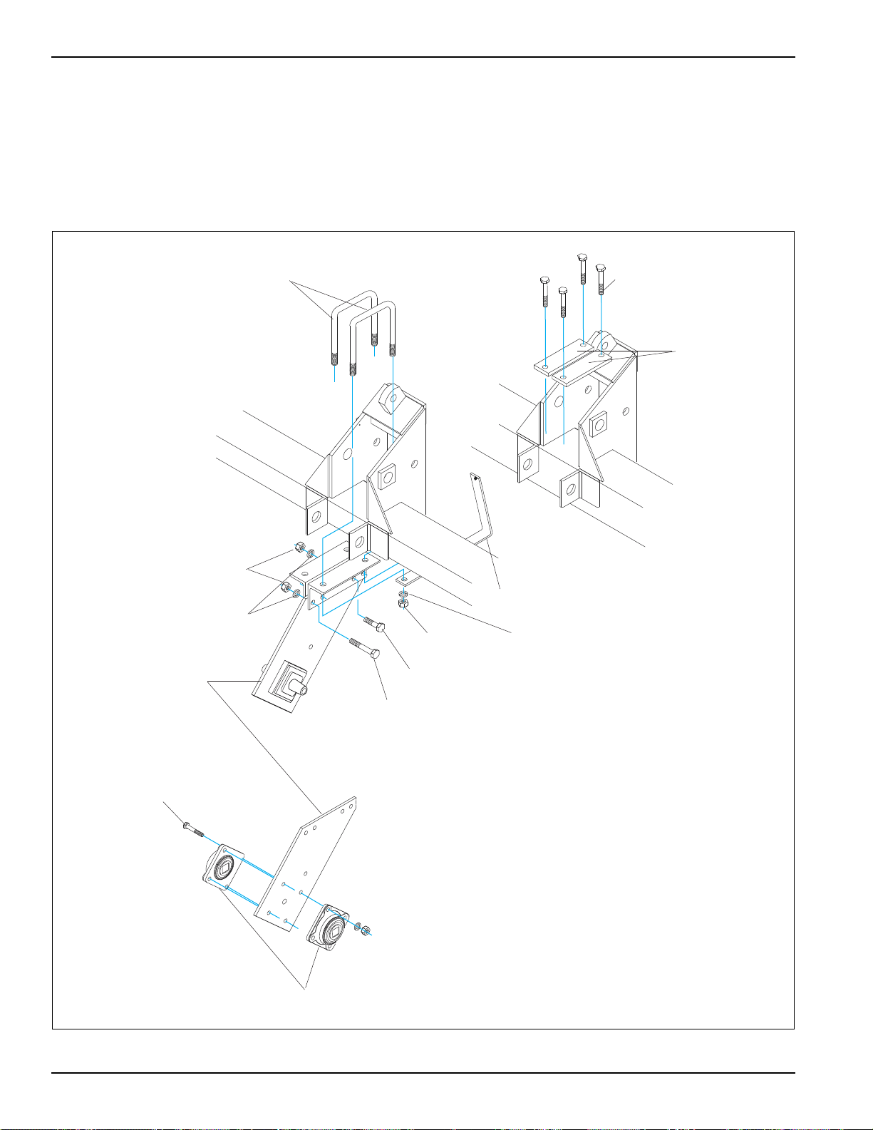
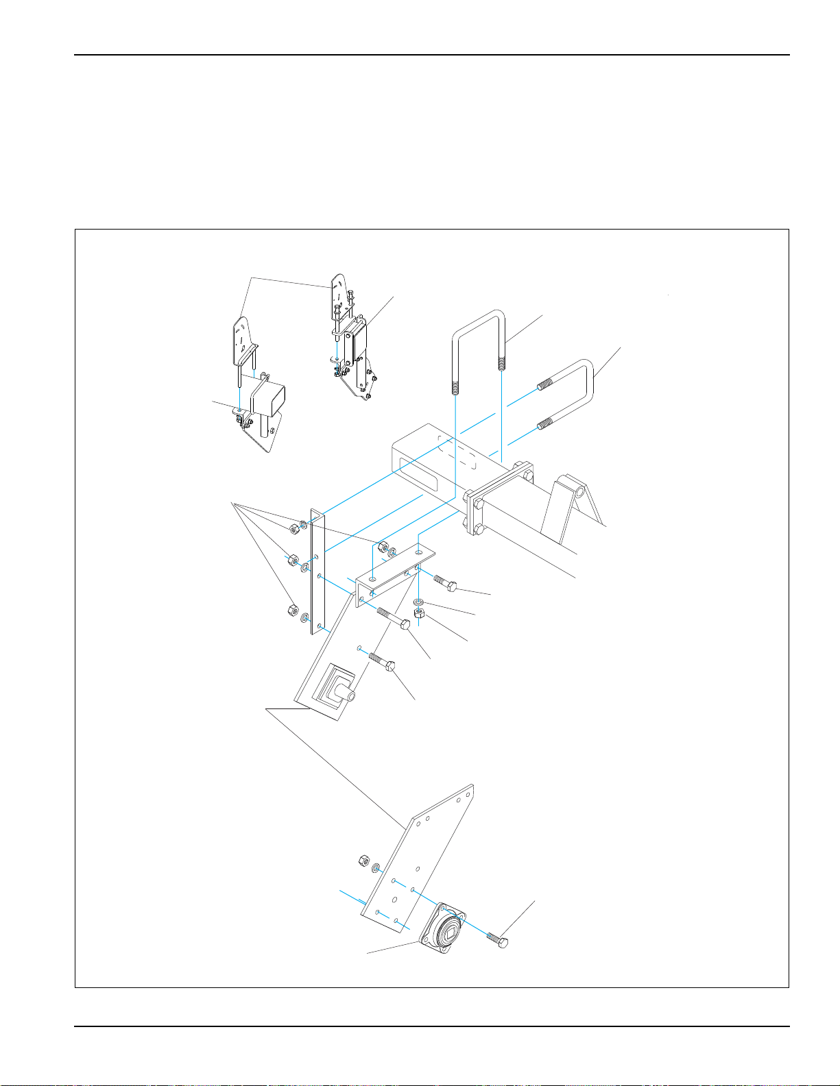
(This end bracket configuration
is supplied on some models.)
SCREW, 1/2” x 1 3/4”
SCREW, 1/2” x 1 1/2”
NUT, 5/8”
LOCKWASHER, 5/8”
SCREW, 1/2” x 1 3/4”
LOCKWASHER, 3/4”
NUT, 3/4”
BEARING ASSEMBLY
END
BRACKET
LOCKWASHER, 1/2”
U-BOLT, 5/8”
SCREW, 1/2” x 1 1/2”
NUT, 1/2”
U-BOLT, 1/2”
18’-20’
MODELS
LIGHT MOUNT
BRACKETS
End Brackets Installation:
1. Start with the right hand end plate and the two angle
members required, See Figure 2-3.
2. Bolt the three pieces together using a 1/2"-13 x
1-3/4" Screw, and a 1/2" Lockwasher and Nut in the
common hole and 1/2"-13 X 1-1/2" Screws, 1/2"
Lockwashers and Nuts for the remaining holes.
3. Attach Light Mount Brackets, using 5/8-11 x 6-11/16
x 5 1/2 U-bolts and 1/2-13 Flange Nuts. (On 18’ - 20’
machines 3K320 Strap, 1J696 Bolt, Washer 9C134
and 2P253 Flange Nut are used in place of U-bolts.)
4. Assemble the left hand end bracket in the same
manner.
Figure 2-3: End Brackets Installation
2-3

ASSEMBLY
IMPORTANT
U-BOLT, 5/8”
MACHINE
BOLTS, 5/8”
STRAP
WHEEL GANG WITH
MALE HARDWARE
Wheel And Axle Assemblies (Wheel Gangs) Installation
Keep the Wheel Gang Assemblies in close alignment
during the assembly procedure. Once you have one
end of the wheel gang fixed, do not move the free
end more than 3” out of alignment in any direction
with the fixed end. Excessive misalignment of the
free end will put stress on the fixed end’s bearing
causing bearing breakage at that location.
On 12’ and wider models the Clamp Axle Assembly
needs to be on the outer end.
1. Align the center frame with the right hand wheel gang
such that the stub shaft is at the same height as the
square bore bearing assembly. The actual placement
of the stub shafts and bearing assembly depends if
the given wheel gang is a male (with stub shafts) or a
female (square bore bearing assemblies). See
Figure 2-4 for male, See Figure 2-5 for female.
2. If the wheel gang has male hardware, slide the
wheel gang end-wise toward the center bracket,
mating the stub shaft with the bearing on the center
bracket.
3. Place a square bore bearing on the opposite wheel
gang stub shaft.
4. Install the right hand end plate assembly on the
center frame: use 5/8-11 x 5 1/2” deep x 6 11/16”
center U-bolt, 5/8” Washers and Nuts on angle
8J099, and 1/2-13 x 7 1/2” deep x 4 1/2” center
U-bolts with 1/2” Lockwashers and Nuts on angle
8J100.
5. Align holes in bearing with holes in end plate and
fasten with Grade 5, 1/2-13 x 1 3/4” Screws, 1/2”
Washers and Nuts facing outwards.
Attach left hand wheel gang in the same manner.
2-4 9J017
Figure 2-4: Wheel and Axle Installation - 1 of 4

ASSEMBLY
U-BOLT, 5/8”
MACHINE
BOLTS, 5/8”
STRAP
WHEEL GANG WITH
FEMALE HARDWARE
SCREW, 1/2” x 1 3/4”
SCREW, 1/2” x 1 1/2”
NUT, 5/8”
LOCKWASHER, 5/8”
END
BRACKET
LOCKWASHER, 1/2”
U-BOLT, 5/8”
SCREW, 1/2” x 1 1/2”
NUT, 1/2”
3K321
STRAP
MACHINE
BOLT, 1/2 x 7 1/2”
MACHINE
BOLT, 5/8 x 8”
U-BOLT, 1/2”
3K320
STRAP
Figure 2-5: Wheel and Axle Installation - 2 of 4
6. If the wheel gang has female hardware, slide the
wheel gang end-wise, toward the center bracket,
mating the square bore bearing with the stub shaft on
the center bracket.
7. Install right hand end plate assembly on the center
frame tube: use 5/8-11 x 5 1/2” deep x 6 11/16”
center U-bolt, 5/8” Washers and Nuts on angle
8J099, and 1/2-13 x 7 1/2” deep x 4 1/2” center
U-bolts with 1/2” Lockwashers and Nuts on angle
8J100. See Figure 2-6. While installing, be sure to
mate the bearing with the end plate stub shaft.
Figure 2-6: Wheel and Axle Installation - 3 of 4
2-5
 Loading...