

Landoll ICON 1632RS User Manual
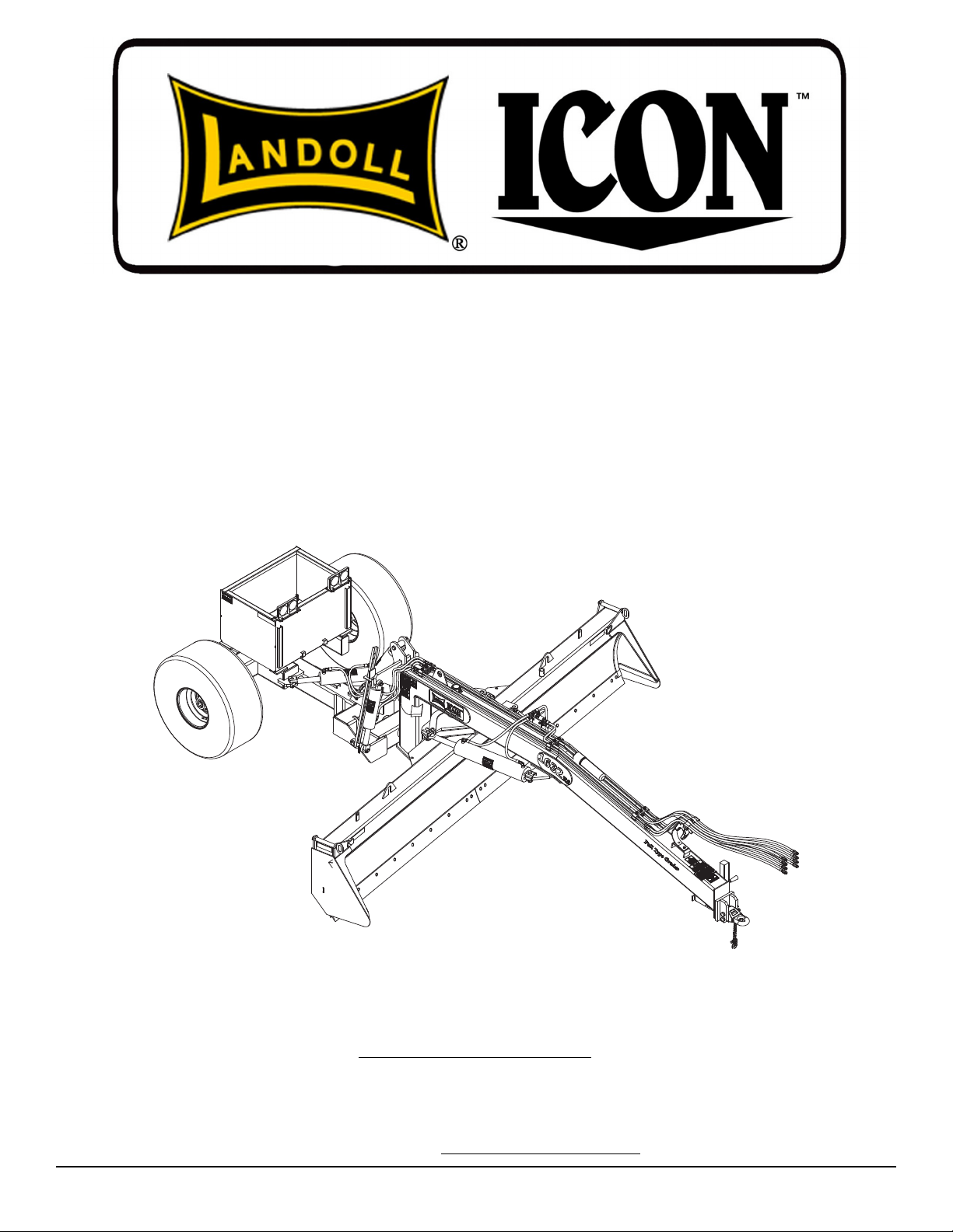
Model 1432/1632/1632RS Grader
Service and Parts
Manual
LANDOLL CORPORATION
1900 North Street
Marysville, Kansas 66508
(785) 562-5381
800-428-5655 ~ WWW.LANDOLL.COM
F-740-1213 12/2013

1-2 F-740-1213 Edition

1 Introduction
Understanding Safety Statements . . . . . . . . . . . . . . . . . . . . . . . . . . . . . . . . . . . . . . . . . . . . . . . . 1-2
2 Standard Specifications
Specifications . . . . . . . . . . . . . . . . . . . . . . . . . . . . . . . . . . . . . . . . . . . . . . . . . . . . . . . . . . . . . . . . . 2-2
3 Safety Information
Introduction . . . . . . . . . . . . . . . . . . . . . . . . . . . . . . . . . . . . . . . . . . . . . . . . . . . . . . . . . . . . . . . . . . 3-1
Owner Assistance . . . . . . . . . . . . . . . . . . . . . . . . . . . . . . . . . . . . . . . . . . . . . . . . . . . . . . . . . . . . . 3-1
Warranty Registration . . . . . . . . . . . . . . . . . . . . . . . . . . . . . . . . . . . . . . . . . . . . . . . . . . . . . . . . . . 3-1
Understanding Safety Statements . . . . . . . . . . . . . . . . . . . . . . . . . . . . . . . . . . . . . . . . . . . . . . . . 3-3
Safety Decals . . . . . . . . . . . . . . . . . . . . . . . . . . . . . . . . . . . . . . . . . . . . . . . . . . . . . . . . . . . . . . . . . 3-7
Pinching or Crushing Danger . . . . . . . . . . . . . . . . . . . . . . . . . . . . . . . . . . . . . . . . . . . . . . . . 3-7
Moving Parts . . . . . . . . . . . . . . . . . . . . . . . . . . . . . . . . . . . . . . . . . . . . . . . . . . . . . . . . . . . . . 3-7
Danger . . . . . . . . . . . . . . . . . . . . . . . . . . . . . . . . . . . . . . . . . . . . . . . . . . . . . . . . . . . . . . . . . . 3-7
Caution . . . . . . . . . . . . . . . . . . . . . . . . . . . . . . . . . . . . . . . . . . . . . . . . . . . . . . . . . . . . . . . . . 3-7
Danger, High Pressure . . . . . . . . . . . . . . . . . . . . . . . . . . . . . . . . . . . . . . . . . . . . . . . . . . . . . 3-7
Horsepower Limits . . . . . . . . . . . . . . . . . . . . . . . . . . . . . . . . . . . . . . . . . . . . . . . . . . . . . . . . . 3-7
Lubrication . . . . . . . . . . . . . . . . . . . . . . . . . . . . . . . . . . . . . . . . . . . . . . . . . . . . . . . . . . . . . . . 3-7
Proper Notification . . . . . . . . . . . . . . . . . . . . . . . . . . . . . . . . . . . . . . . . . . . . . . . . . . . . . . . . . 3-7
Table of Contents
Storage Recommendations . . . . . . . . . . . . . . . . . . . . . . . . . . . . . . . . . . . . . . . . . . . . . . . . . . . . . . 3-7
4 Assembly and Lubrication
Assembly and Lubrication Check List . . . . . . . . . . . . . . . . . . . . . . . . . . . . . . . . . . . . . . . . . . . . . 4-1
Lubrication Maintenance . . . . . . . . . . . . . . . . . . . . . . . . . . . . . . . . . . . . . . . . . . . . . . . . . . . . . . . . 4-1
Storage . . . . . . . . . . . . . . . . . . . . . . . . . . . . . . . . . . . . . . . . . . . . . . . . . . . . . . . . . . . . . . . . . . . . . . 4-1
5 Hookup and Operation
Tie Strap Designations . . . . . . . . . . . . . . . . . . . . . . . . . . . . . . . . . . . . . . . . . . . . . . . . . . . . . . . . . 5-1
Hookup to the Remote . . . . . . . . . . . . . . . . . . . . . . . . . . . . . . . . . . . . . . . . . . . . . . . . . . . . . . . . . . 5-2
Learning to Operate the Grader . . . . . . . . . . . . . . . . . . . . . . . . . . . . . . . . . . . . . . . . . . . . . . . . . . 5-2
6 Illustrated Parts List
General Assembly . . . . . . . . . . . . . . . . . . . . . . . . . . . . . . . . . . . . . . . . . . . . . . . . . . . . . . . . . . . . . 6-1
Grader Assembly . . . . . . . . . . . . . . . . . . . . . . . . . . . . . . . . . . . . . . . . . . . . . . . . . . . . . . . . . . . . . . 6-6
F-740-1213 Edition i

Grader Assembly Standard Models . . . . . . . . . . . . . . . . . . . . . . . . . . . . . . . . . . . . . . . . . . . . . . 6-10
Item . . . . . . . . . . . . . . . . . . . . . . . . . . . . . . . . . . . . . . . . . . . . . . . . . . . . . . . . . . . . . . . . . . . . . . . . 6-10
Part No. . . . . . . . . . . . . . . . . . . . . . . . . . . . . . . . . . . . . . . . . . . . . . . . . . . . . . . . . . . . . . . . . . . . . . 6-10
Description . . . . . . . . . . . . . . . . . . . . . . . . . . . . . . . . . . . . . . . . . . . . . . . . . . . . . . . . . . . . . . . . . . 6-10
. . . . . . . . . . . . . . . . . . . . . . . . . . . . . . . . . . . . . . . . . . . . . . . . . . . . . . . . . . . . . . . . . . . . . . . . . . . . 6-10
Hub And Axle Assembly . . . . . . . . . . . . . . . . . . . . . . . . . . . . . . . . . . . . . . . . . . . . . . . . . . . . . . . 6-12
7,000 Lb. Sidewind Jack Assembly . . . . . . . . . . . . . . . . . . . . . . . . . . . . . . . . . . . . . . . . . . . . . . 6-14
Hydraulic Assembly . . . . . . . . . . . . . . . . . . . . . . . . . . . . . . . . . . . . . . . . . . . . . . . . . . . . . . . . . . . 6-18
Hydraulic Cylinder, 4 X 12 . . . . . . . . . . . . . . . . . . . . . . . . . . . . . . . . . . . . . . . . . . . . . . . . . . . . . . 6-20
Hydraulic Cylinder, 4 X 16 . . . . . . . . . . . . . . . . . . . . . . . . . . . . . . . . . . . . . . . . . . . . . . . . . . . . . . 6-22
Hydraulic Cylinder, 5 X 24 . . . . . . . . . . . . . . . . . . . . . . . . . . . . . . . . . . . . . . . . . . . . . . . . . . . . . . 6-24
Light Kit (Option) . . . . . . . . . . . . . . . . . . . . . . . . . . . . . . . . . . . . . . . . . . . . . . . . . . . . . . . . . . . . . 6-25
Decal Kit . . . . . . . . . . . . . . . . . . . . . . . . . . . . . . . . . . . . . . . . . . . . . . . . . . . . . . . . . . . . . . . . . . . . 6-30
Gauge Wheel Kit (Option) . . . . . . . . . . . . . . . . . . . . . . . . . . . . . . . . . . . . . . . . . . . . . . . . . . . . . . 6-32
Grader Snow/Dirt Kit (Option) . . . . . . . . . . . . . . . . . . . . . . . . . . . . . . . . . . . . . . . . . . . . . . . . . . . 6-34
7 Numerical Index
ii F-740-1213 Edition

Chapter 1
Introduction
The Landoll/Icon Model 1632RS Grader is a quality product designed to give years of trouble free performance. By
following each section of this manual, your system will perform as designed for you and your operation
CHAPTER 1 gives basic instructions on the use of this manual.
CHAPTER 2 gives product specifications. These specifications supply lengths and measures for your
equipment. A Standard Bolt Torque Table is provided to give guidelines for bolt torques to
be used when servicing this product.
CHAPTER 3 contains assembly instructions for your Model 1632RS Grader. When these procedures
are correctly followed, your equipment should provide you years of trouble-free operation
and service.
CHAPTER 4 instructs how to operate your equipment before using it, and describes adjustments
needed. It also gives practical advice for the care and maintenance of your Landoll
equipment. Drawings in this section locate adjustment points on the equipment.
NOTE: IF THE EQUIPMENT IS IMPROPERLY ASSEMBLED OR MAINTAINED, THE
WARRANTY IS VOID. IF YOU HAVE ANY QUESTIONS CONTACT:
LANDOLL CORPORATION
1900 NORTH STREET
MARYSVILLE, KANSAS 66508
or phone:
(785) 562-5381 or
(800) 428-5655
or FAX:
(888) 527-3909
CHAPTER 5 is a troubleshooting guide to aid in diagnosing and solving problems with the equipment.
PARTS LIST is a separate manual showing the various assemblies, subassemblies, and systems.
Refer to that manual when ordering Landoll replacement parts. Order parts from your
Landoll dealer.
WARRANTY The Warranty Registration form is included with the product documents. Fill it out and
mail it within 15 days of purchase.
NOTE: IMPROPER ASSEMBLY, MODIFICATION, OR MAINTENANCE OF YOUR
LANDOLL MACHINE CAN VOID YOUR WARRANTY.
COMMENTS Address comments or questions regarding this publication to:
LANDOLL CORPORATION
1900 NORTH STREET
MARYSVILLE, KANSAS 66508
ATTENTION: PUBLICATIONS -DEPT. 55
1-1

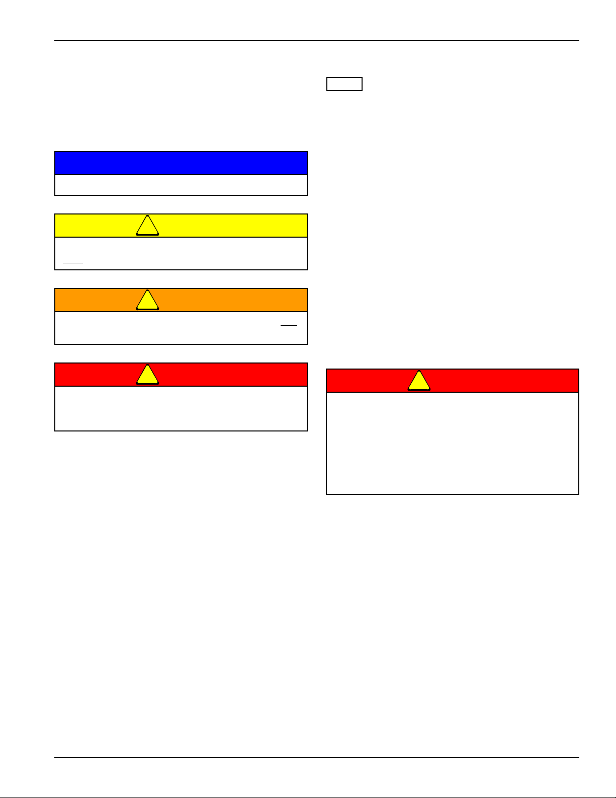
INTRODUCTION
DANGER
WARNING
CAUTION
NOTE
NOTE
Understanding Safety Statements
You will find various types of safety information on the
following pages and on the machine signs (decals)
attached to the vehicle. This section explains their
meaning.
The Safety Alert Symbol means ATTENTION! YOUR
SAFETY IS INVOLVED!
Danger means a life-threatening situation exists.
Death can occur if safety measures or
instructions on this label are not properly
followed.
Warning means serious injury or death can occur
if safety measures or instructions on this label
are not properly followed.
Caution means serious equipment or other
property damage can occur if instructions on this
label are not properly followed.
Means that failure to follow these instructions could
cause damage to the equipment or cause it to operate
improperly.
Make sure you read and understand the information
contained in this manual and on the machine signs
(decals) before you attempt to operate or maintain this
vehicle.
The safety statements contained in this manual relate to
the operation of the Model 1632RS Grader.
1-2 F-740-1213 Edition

Chapter 2
Standard Specifications
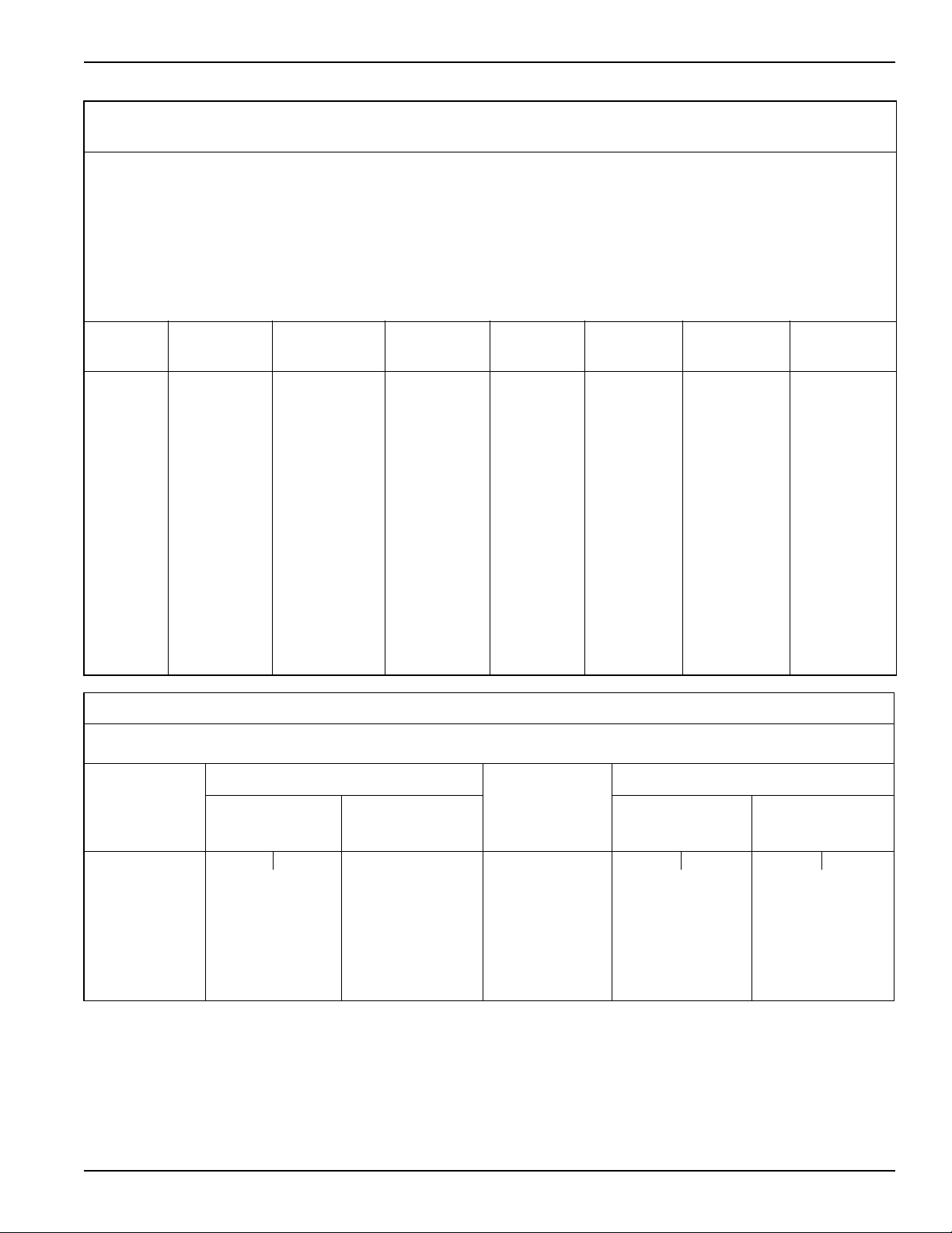
1432/1632 GRADER
MODEL BLADE WIDTH TRANSPORT WIDTH EST. WEIGHT (LBS.)
1432 14’0” 8’-4” 5,100
1632 16’-0” 8’-4” 5,300
1632RS 16’-0” 8’-4” 5,660
TIRE INFLATION
TIRE
SIZE
19L x 16.1
12 ply
20.5 x 8.0-10 Load Range D/ 1,320 lb. 70 psi
Center Frame Spindle Nuts:
Inner 50 Ft./Lbs.
Outer 300 Ft./Lbs.
Center Frame Wheel Nuts: 450 - 500 Ft./Lbs.
Wing Frame Wheel Nuts: 85 - 100 Ft./Lbs.
Disc Gang Shafts 1,200 Ft./Lbs.
9/16-18 Lug Bolts and Nuts (Heavy Duty Disc) 80 - 90 ft. lbs
5/8-18 Lug Bolts and Nuts (Heavy Duty Disc) 85 - 100 ft. lbs
MANUFACTURER
Firestone or
equivalent
TIRE
PLY/LOAD
RATING
Farm Implement Tread
6600 lbs. @ 30 mph
SPECIFIC BOLT TORQUES
INFLATION PRESSURE
(PSI) (MAX.)
36 psi
2-1

STANDARD SPECIFICATIONS
Specifications
• Model 1432
• Standard 7” x 8’ cutting edges on 16’ x 32” blade.
• Standard folding box ends, to convert to box scraper.
• Four way operation to raise/lower, blade tilt side to
side, and blade rotation. And rear steer.
• Pintle style hitch w/bolt on hammer strap. Rated at
68,800 lbs.
• Maximum tractor horsepower is 300 hp.
• Shipping Weight
1432 - 5100 lbs.
• Overall length is 23’.
• Overall width with hydraulics attached is 9’-6”.
• Transport width with hydraulics unpinned, and in
transport position is 8’-4”.
• Blade swing left/right is 50°, tilt side to side is 15°,
blade clearance at full raised position is 18". And rear
steer adds 5’ extension of blade on either side.
• Tires are 19 x 16.1, on 8 bolt rims and 8000 lb.
spindles (35 psi max. inflation)
• Weight box should be filled prior to use. It holds app.
1/2 yd. of concrete (1500#)
• Hydraulic cushion valve for blade breakaway, upon
solid impact. (set at 2500psi)
• Standard light package.
• Cylinders are welded industrial
— 5 x 24 blade swing
— 4 x 12 tilt
— 4 x 16 raise/lower
— 4 x 16 rear steer
• 9 total grease locations.
• Requires 4 remotes on the tractor (8 hoses).
• Standard angle gauge.
• 3000 psi hydraulic hoses.
•
•
• Model 1632.1632RS
• Standard 6” x 8’ cutting edges on 16’ x 32” blade.
• Standard folding box ends, to convert to box scraper.
• Four way operation to raise/lower, blade tilt side to
side, and blade rotation. And rear steer.
• Pintle style hitch w/bolt on hammer strap. Rated at
68,800 lbs.
• Maximum tractor horsepower is 300 hp.
• Shipping Weight
1632 - 5300 lbs.
1632RS - 5,660 lbs.
• Overall length is 23’.
• Overall width with hydraulics attached is 9’-6”.
• Transport width with hydraulics unpinned, and in
transport position is 8’-4”.
• Blade swing left/right is 50°, tilt side to side is 15°,
blade clearance at full raised position is 18". And rear
steer adds 5’ extension of blade on either side.
• Tires are 19 x 16.1, on 8 bolt rims and 8000 lb.
spindles (35 psi max. inflation)
• Weight box should be filled prior to use. It holds app.
1/2 yd. of concrete (1500#)
• Hydraulic cushion valve for blade breakaway, upon
solid impact. (set at 2500psi)
• Standard light package.
• Cylinders are welded industrial
— 5 x 24 blade swing
— 4 x 12 tilt
— 4 x 16 raise/lower
— 4 x 16 rear steer
• 9 total grease locations.
• Requires 4 remotes on the tractor (8 hoses).
• Standard angle gauge.
• 3000 psi hydraulic hoses.
•
2-2 F-740-1213 Edition
STANDARD SPECIFICATIONS
LANDOLL CORPORATION
GENERAL TORQUE SPECIFICATIONS (REV. 4/97)
THIS CHART PROVIDES TIGHTENING TORQUES FOR GENERAL PURPOSE APPLICATIONS WHEN SPECIAL TORQUES ARE NOT SPECIFIED ON PROCESS
OR DRAWING.
ASSEMBLY TORQUES APPLY TO PLATED NUTS AND CAPSCREWS ASSEMBLED WITHOUT SUPPLEMENTAL LUBRICATION (AS RECEIVED CONDITION). THEY
DO NOT APPLY IF SPECIAL GRAPHITE MOLY-DISULFIDE OR OTHER EXTREME PRESSURE LUBRICANTS ARE USED.
WHEN FASTENERS ARE DRY (SOLVENT CLEANED), ADD 33% TO AS RECEIVED CONDITION TORQUE.
BOLT HEAD IDENTIFICATION MARKS INDICATE GRADE AND MAY VARY FROM MANUFACTURER TO MANUFACTURER.
THICK NUTS MUST BE USED ON GRADE 8 CAPSCREWS.
USE VALUE IN [ ] IF USING PREVAILING TORQUE NUTS.
TORQUE IS SPECIFIED IN FOOT POUNDS
UNC
Size
SAE Grade2SAE Grade5SAE Grade
8
UNF
Size
SAE Grade 2SAE Grade5SAE Grade
8
1/4-20 4 [5] 6 [7] 9 [11] 1/4-28 5 [6] 7 [9] 10 [12]
5/16-18 8 [10] 13 [16] 18 [22] 5/16-24 9 [11] 14 [17] 20 [25]
3/8-16 15 [19] 23 [29] 35 [43] 3/8-24 17 [21] 25 [31] 35 [44]
7/16-14 24 [30] 35 [43] 55 [62] 7/16-20 27 [34] 40 [50] 60 [75]
1/2-13 35 [43] 55 [62] 80 [100] 1/2-20 40 [50] 65 [81] 90 [112]
9/16-12 55 [62] 80 [100] 110 [137] 9/16-18 60 [75] 90 [112] 130 [162]
5/8-11 75 [94] 110 [137] 170 [212] 5/8-18 85 [106] 130 [162] 180 [225]
3/4-10 130 [162] 200 [250] 280 [350] 3/4-16 150 [188] 220 [275] 320 [400]
7/8-9 125 [156] 320 [400] 460 [575] 7/8-14 140 [175] 360 [450] 500 [625]
1-8 190 [237] 408 [506] 680 [850] 1-14 210 [263] 540 [675] 760 [950]
1-1/8-7 270 [337] 600 [750] 960 [1200] 1-1/8-12 300 [375] 660 [825] 1080 [1350]
1-1/4-7 380 [475] 840 [1050] 1426 [1782] 1-1/4-12 420 [525] 920 [1150] 1500 [1875]
1-3/8-6 490 [612] 110 [1375] 1780 [2225] 1-3/8-12 560 [700] 1260 [1575] 2010 [2512]
1-1/2-6 650 [812] 1460 [1825] 2360 [2950] 1-1/2-12 730 [912] 1640 [2050] 2660 [3325]
1-3/4-5 736 [920] 1651 [2063] 2678 [3347] 1-3/4-12 920 [1150] 2063 [2579] 3347 [4183]
METRIC
COARSE THREAD METRIC CLASS 10.9 FASTENERS AND CLASS 10.0 NUTS AND THROUGH HARDENED FLAT WASHERS, PHOSPHATE COATED, ROCKWELL
“C” 38-45.
USE VALUE IN [ ] IF USING PREVAILING TORQUE NUTS.
Nominal
Thread
Diameter
mm
Standard Torque Nominal
Newton-
Meters
Foot-
Pounds
Thread
Diameter
mm
Standard Torque
Newton-
Meters
Foot-
Pounds
6 10 [14] 7 [10] 20 385 [450] 290 [335]
7 16 [22] 12 [16] 24 670 [775] 500 [625]
8 23 [32] 17 [24] 27 980 [1105] 730 [825]
10 46 [60] 34 [47] 30 1330 [1470] 990 [1090]
12 80 [101] 60 [75] 33 1790 [1950] 1340 [1450]
14 125 [155] 90 [115] 36 2325 [2515] 1730 [1870]
16 200 [240] 150 [180] 39 3010 [3210] 2240 [2380]
18 275 [330] 205 [245]
Table 2-1: General Torque Specifications
2-3

STANDARD SPECIFICATIONS
LANDOLL CORPORATION
HYDRAULIC FITTING TORQUE SPECIFICATIONS
THIS CHART PROVIDES TIGHTENING TORQUES FOR HYDRAULIC FITTING APPLICATIONS WHEN SPECIAL TORQUES ARE NOT SPECIFIED ON PROCESS
OR DRAWING.
ASSEMBLY TORQUES APPLY TO PLATED CARBON STEEL AND STAINLESS STEEL FITTINGS ASSEMBLED WITHOUT SUPPLEMENTAL LUBRICATION (AS
RECEIVED CONDITION). THEY DO NOT APPLY IF SPECIAL GRAPHITE MOLY-DISULFIDE OR OTHER EXTREME PRESSURE LUBRICANTS ARE USED.
BRASS FITTINGS AND ADAPTERS - 65% OF THE TORQUE VALUE FOR STEEL. STAINLESS STEEL, ALUMINUM AND MONEL - THREADS ARE TO BE
LUBRICATED
.
TORQUE IS SPECIFIED IN FOOT POUNDS
Dash Size 37 Degree JIC O-Ring (ORS) O-Ring Boss (ORB)
-4 11-13 15-17 13-15
-5 14-16 — 21-23
-6 20-22 34-36 25-29
-8 43-47 58-62 40-44
-10 55-65 100-110 57.5-62.5
-12 80-90 134-146 75-85
-16 115-125 202-218 109-121
-20 160-180 248-272 213-237
-24 185-215 303-327 238-262
-32 250-290 — 310-340
o
37
JIC, ORS, & ORB (REV. 10/97)
PARKER BRAND FITTINGS
GATES BRAND FITTINGS
Dash Size 37 Degree JIC O-Ring (ORS) O-Ring Boss (ORB)
-4 10-11 10-12 14-16
-5 13-15 — —
-6 17-19 18-20 24-26
-8 34-38 32-40 37-44
-10 50-56 46-56 50-60
-12 70-78 65-80 75-83
-14 — 65-80 —
-16 94-104 92-105 111-125
-20 124-138 125-140 133-152
-24 156-173 150-180 156-184
-32 219-243 — —
AEROQUIP BRAND FITTINGS
Dash Size 37 Degree JIC O-Ring (ORS) O-Ring Boss (ORB)
-4 11-12 10-12 14-16
-5 15-16 — 18-20
-6 18-20 18-20 24-26
-8 38-42 32-35 50-60
-10 57-62 46-50 72-80
-12 79-87 65-70 125-135
-14 — — 160-180
-16 108-113 92-100 200-220
-20 127-133 125-140 210-280
-24 158-167 150-165 270-360
-32 245-258 — —
Table 2-2: Hydraulic Fitting Torque Specifications
2-4 F-740-1213 Edition

Chapter 3
1-010006
Safety Information
Introduction
This manual is compiled as a guide for owners and
operators of the Pull Type Grader. Read it carefully so as
to be able to follow the suggestions made. Please take
time to understand the proper maintenance schedule and
SAFE operation of your equipment.
In the event that a new and inexperienced operator is
placed in charge of running the equipment, they should
read and understand, that part of the manual for proper
maintenance and SAFE operation, and to be trained in
regard by an experienced operator.
Owner Assistance
If customer service or repairs are needed, contact your
Icon dealer. They have trained personnel, parts and
service equipment specially designed for Icon products.
Your machine’s parts should only be replaced with Icon
parts. Have the Serial Number and complete Model
Number available when ordering parts from your Icon
dealer (See Figure 3-1.)
Warranty Registration
Be certain to register the grader, by online registration at
www.landoll.com
order to be on file at Landoll and eligible for Warranty.
Take time to read and understand the Warranty for this
product. That Warranty is printed in the Owner’s Manual
(See Figure 3-2), and a separate copy enclosed in the
packet.
ICON/Landoll reserves the right to make changes and/or
add improvements to it’s products at any time without
obligation to previously manufactured equipment.
ICON/Landoll recommends a maximum horsepower of
the pulling tractor for your grader to be 300 hp. Additional
power may shorten the life of your grader and will alter
the Warranty.
Please take time to complete the following information for
your personal reference, should you need to contact your
Dealer with questions or parts needs.
MODEL_____________________________________
SERIAL #____________________________________
DATE OF PURCHASE__________________________
DEALER NAME________________________________
We at ICON/Landoll wish to thank you for purchasing our
product. We have spent considerable time and effort to
research, design, test and develop this machine and are
confident it will serve you in the use for which it was
designed.
within 10 days of purchase or lease, in
Figure 3-1: ID Plate
3-1

SAFETY INFORMATION
LANDOLLCORPORATION
ProductWarranty
LANDOLLCORPORA TION1600W.8 St.BeloitKS67420
(referredtoasLANDOLLinthisdocument)
LANDOLL
LANDOLL,
LANDOLL
LANDOLL,
th
shallWarrantworkmanshipandmaterialsonthe
foraperiodof12monthsfromthedateoforiginalpurchase,lease,
orrental,fromtheoriginalDealer,andinaccordancewiththefollowingterms
andconditions.
ShouldanypartorcomponentfailwithintheWarrantyperiod,andunder
normaluseconditions,
LANDOLL shallsupplyanewpartorcomponentfor
replacementthroughtheoriginalDealer.Costofnormalgroundfreight,for
thatpartorcomponenttotheDealer,shallbepaidbyLANDOLL.Repairand
replacementlaborcost,fromtheoriginalDealer,shallbepaidbyLANDOLLat
aratenegotiatedbyLANDOLL.
Nofurtherexpenseshallbepaidby includingbut notlimitedto,
lossoftimeorincome.
shallnotprovideWarrantyonanypartorcomponentthathas
failedduetoabuse,misuse,alteration,impropermaintenance,ornormal
wear.Failureoccurringwhilebeingpulledbyatractorinexcessofengine
horsepower,asdescribedintheownersmanualand/orpostedonthe
machine,isconsideredabuseandmisuseandshallnotreceiveWarranty.
Warrantyappliesonlytonormal.intermittentagriculturaluse,andnot
commercialorindustrialuse.
Inregardtosomecomponentsmanufacturedbyothercompaniesandsold
by includingbut
notlimitedtotires,saidWarrantyshallbe
providedsolelybythatmanufacturingcompany.
ThisWarrantyappliestoproductssoldintheUnitedStatesandCanada,
andismadeexpresslyinplaceofallotherwarranties,expressedorimplied.
ICONFarm
Products
3-2 F-740-1213 Edition
Figure 3-2: Product Warranty
Understanding Safety
NOTICE
CAUTION
WARNING
DANGER
NOTE
DANGER
Statements
You will find various types of safety information on the
following pages and on the machine decals (signs)
attached to the implement. This section explains their
meaning.
Special notice - read and thoroughly understand.
Proceed with caution. Failure to heed caution
may
cause injury to person or damage product.
Proceed with caution. Failure to heed warning will
cause injury to person or damage product.
SAFETY INFORMATION
You should read and understand the information
contained in this manual and on the machine decals
before you attempt to operate or maintain this equipment.
• Examine safety decals and be sure you have the
correct safety decals for the machine. See Safety Sign
and Locations in Safety Section for decal locations
See Figures 3-3 through 3-5 Order replacement
decals through your Icon dealer.
• Keep these signs clean so they can be observed
readily. It is important to keep these decals cleaned
more frequently than the machine. Wash with soap
and water or a cleaning solution as required.
• Replace decals that become damaged or lost. Also, be
sure that any new machine components installed
during repair include decals which are assigned to
them by the manufacturer.
• When applying decals to the machine, be sure to
clean the surface to remove any dirt or residue. Where
possible, sign placement should protect the sign from
abrasion, damage, or obstruction from mud, dirt, oil
etc.
Proceed with extreme caution. Failure to heed
notice will cause injury or death to person and/or
damage product.
• Keep Riders Off of Machinery
• Do not allow anyone to ride on tractor or
machine. Riders could be struck by foreign
objects or thrown from the machine.
• Never allow children to operate equipment.
• Keep bystanders away from machine during
operation.
3-3
SAFETY INFORMATION
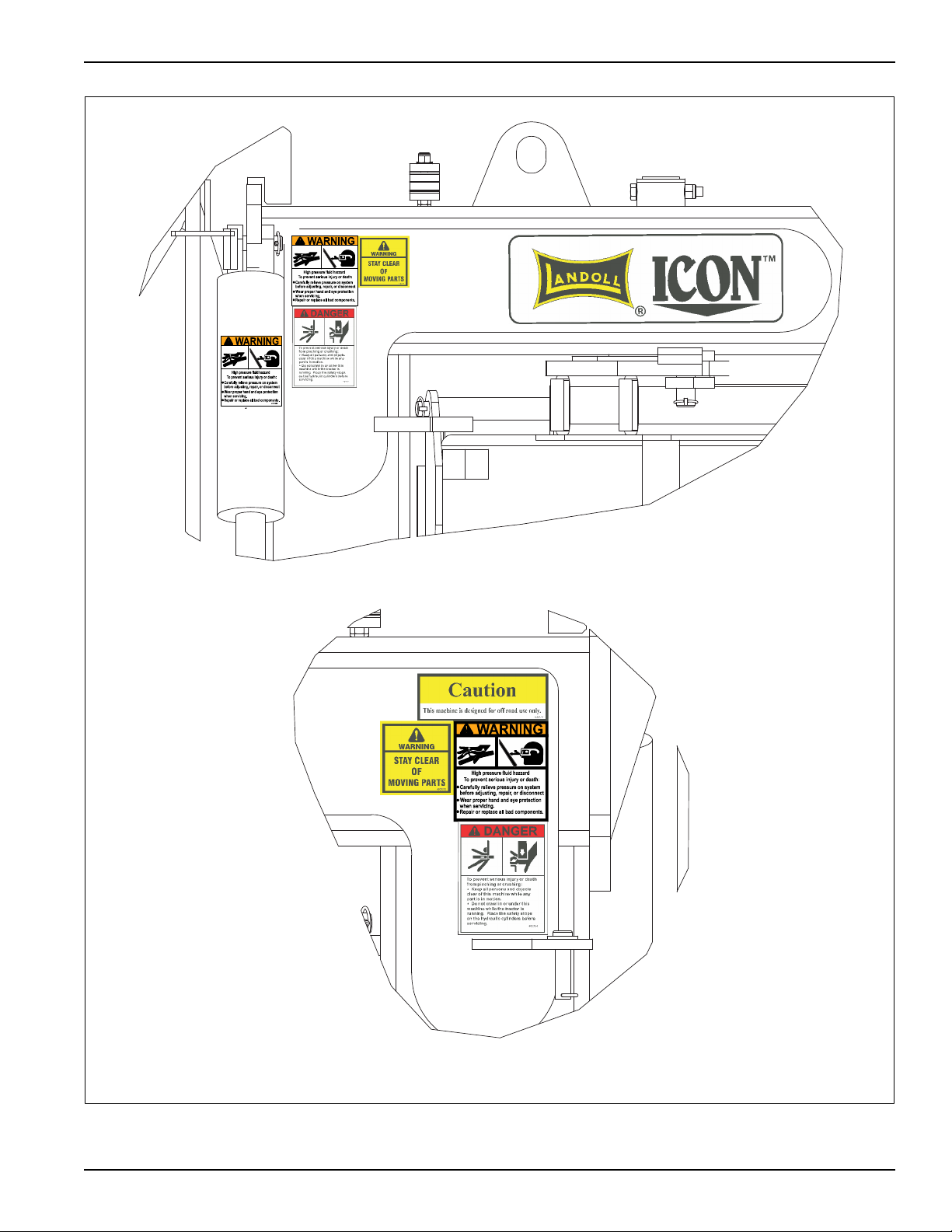
1632rs safety decals
SEE DETAIL B
SEE DETAIL C
SEE DETAIL A
3-4 F-740-1213 Edition
Figure 3-3: Safety Decal Locations (1 of 3)
SAFETY INFORMATION
DETAIL A
1632RS DECALS 2
DETAIL B
4000931
4000931
Figure 3-4: Safety Decal Locations (2 of 3)
3-5

SAFETY INFORMATION
DETAIL C
1632RS safety decals 3
4000625
3-6 F-740-1213 Edition
Figure 3-5: Safety Decal Locations (3 of 3)
SAFETY INFORMATION
NOTE
NOTE
NOTE
NOTE
CAUTION
Safety Decals
See Figures 3-3 through 3-5 for decal locations.
Replace all missing or damaged safety signs/decals.
Pinching or Crushing Danger
1. Moving parts that are operated by hydraulic pressure
can cause serious injury or death.
2. Use extreme caution when working around any
moving part.
3. Do not allow any person to be on or near the
machine while it is in motion.
Moving Parts
1. Be aware of all moving parts of the machine.
2. Do not allow anyone to be near, or on the machine
while operating any moving part.
Danger
1. Read and understand the operator’s manual before
using the machine.
2. Allow no person to operate the machine before
reading the manual and being instructed on proper
operation.
Horsepower Limits
1. Each machine is rated for it’s horsepower limits.
2. If the posted limits are exceeded, damage to the
machine may occur, and the Warranty will void.
300 maximum engine h.p. is only applicable if the grader
is equipped with the 2nd cylinder.
Lubrication
1. Lubrication information is placed near each zerk.
2. Proper maintenance should be followed to assure the
working life of the machine.
Proper Notification
1. Contact the proper authorities before you dig.
2. When digging in a populated area, it is
recommended that a call be made to area utilities to
establish the local of any buried pipes, lines, or
structures. When digging in open areas, research
and know the local of any underground structures
and objects.
3. Striking the blades or bits against buried objects can
cause damage to the machine, and is considered as
abuse to the scraper.
Caution
1. This machine is designed for off road use only.
Danger, High Pressure
1. High pressure fluid can cause serious damage to
hands and eyes.
2. Carefully relieve pressure before attempting any
3. adjustments.
4. Tighten all fittings before applying pressure.
If fluid is sprayed into eyes or injected into skin, see a
doctor immediately!
Storage Recommendations
If the machine is being stored or not in use for a long
period of time, it is recommended that a coating of heavy
grease be applied to the exposed chrome cylinder rods.
This will help to protect the coating from moisture and
rust during this time.
Be certain to remove the cylinder stops before
using the grader. The stops are to be pinned in
the holder, located on the rear frame.
Failure to remove the stops will result in damage
to the stop or cylinder.
3-7

SAFETY INFORMATION
3-8 F-740-1213 Edition

Chapter 4
Assembly and Lubrication
Assembly and Lubrication Check List
1. Install and pin pivot frame to tongue frame.
2. Pin rear frame to center pivot frame
3. Attach grader hitch and assure proper movement.
4. Install pivot pins, and insert all retaining clips.
5. Install lift/tilt pivot cylinders. Install all cylinder pins
and retaining clips.
6. Install box ends and components. Fold and check to
assure they function properly.
7. Install axle and wheel components. Visually inspect
tires.
8. Route hydraulic lines and tighten.
9. Install safety lighting components, route wiring, and
install plug retainer. Cycle and check lighting system
with 12 volt system tester.
10. Lubricate all moving components with high temp
grease.
11. Fill hydraulic systems with Mobil 424 hydraulic oil
using hydraulic pump, activate all moving parts and
bleed air from the system. Hold 3000 psi. hydraulic
pressure against all cylinders, fittings, and hoses.
12. Check hydraulic components for leaks.
13. Recheck that all retainers are installed.
14. Assure the rear steer components function properly.
15. Clean and touch up paint the machine.
16. Attach operators manual and container.
17. Apply the safety, operations, and lube identification
decals. Attach plastic envelope with warranty info,
and this check list, at the front of the hose holder.
18. For ease of transporting, assure that the blade is
level, and in the transport position before leaving
shop.
Lubrication Maintenance
1. Ta ble 4 - 1 specifies the number and the period of
lubrication points on the 1632RS Grader. Proper
maintenance of your machine will, under normal
operating conditions, help to keep it operating at or
near its peak performance for an extended period of
time. Proper maintenance is also a condition of
keeping your warranty in good status (See
Figure 4-1.)
2. When lubricating the 1632RS, SAE multi-purpose EP
grease, or EP grease with 3-5% molybdenum sulfide
is recommended. Wipe soil from fittings before
greasing. Replace any lost or broken fittings
immediately.
3. Regular lubrication will extend service life,
particularly in severe operating conditions.
Storage
1. The service life of the 1632RS Grader will be
extended by proper off-season storage practices.
Prior to storing the unit, complete the following
procedures:
a. Completely clean the unit.
b. Inspect the machine for worn or defective parts.
Replace as needed.
c. Repaint all areas where the original paint is worn
off.
d. Grease all exposed metal surfaces of shanks,
points and discs.
e. Apply a light coating of oil or grease to exposed
cylinder rods to prevent them from rusting.
f. Lubricate each point of the machine as stated in
“Lubrication Maintenance” on page 4-1.
2. Store the unit in a shed or under a tarpaulin to protect
it from the weather. The ground tools and tires should
rest on boards, or some other object, to keep them
out of the soil.
4-1
ASSEMBLY AND LUBRICATION
4
1
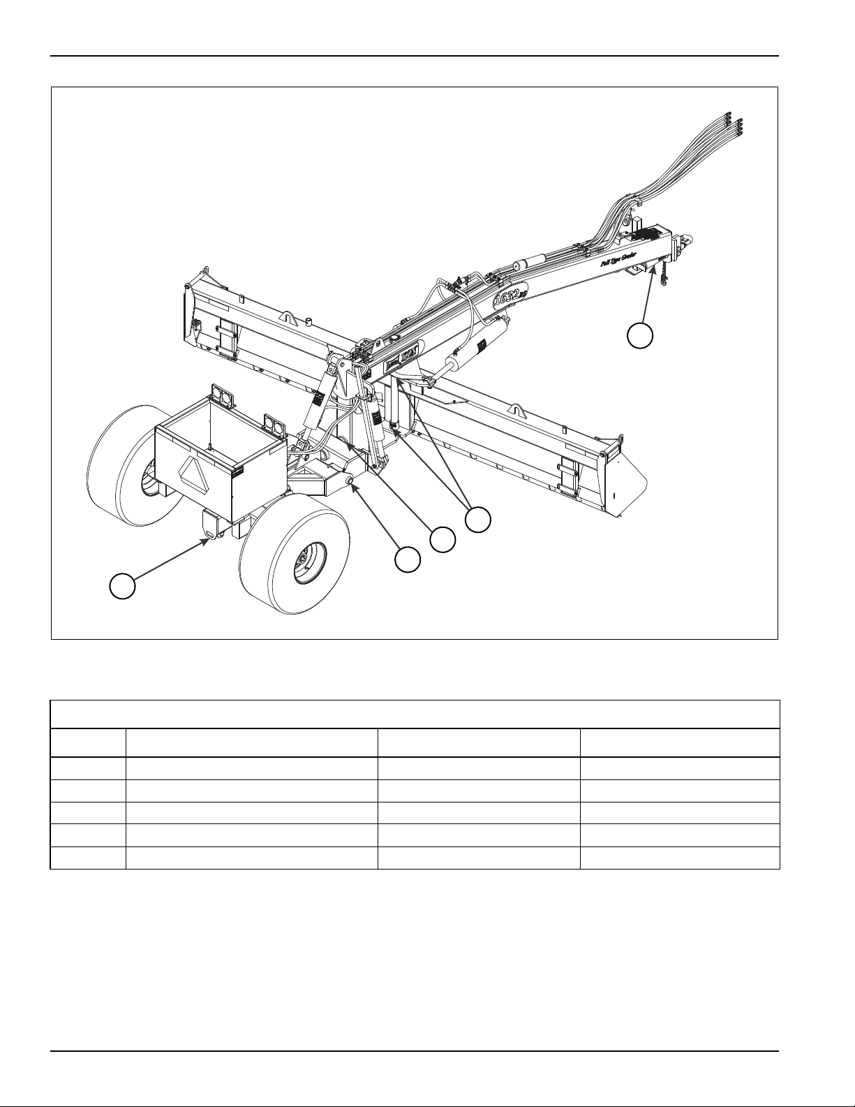
1632 rs lubrication chart
2
5
3
Figure 4-1: Lubrication Schedule
LUBRICATION TABLE
ITEM DESCRIPTION NO. OF LUBE POINTS INTERVAL
1 REAR AXLE PIVOT 1 DAILY
2 REAR AXLE SUPPORT PIN 2 DAILY
3 CENTER BLADE PIN 2 DAILY
4 HITCH PIVOT 2 DAILY
5 CENTER PIVOT 1 DAILY
Table 4-1: Lubrication Table
4-2 F-607-1213 Edition
 Loading...