

Landoll HSB 71-1 User Manual

®
SOIL BUILDER
Coulter Chisel - Extended Frame
Models: SB, HSB 71-1 through 131-1
s
Operator’s Manual
LANDOLL CORPORATION
1900 North Street
Marysville, Kansas 66508
(785) 562-5381
800-428-5655 ~ WWW.LANDOLL.COM
791rev0514 1K705


Contents
Contents
Introduction . . . . . . . . . . . . . . . . . . . . . . . . . . . . . . . . . . . . . . . . . . . . . . . . . . . . . . . . . . . . . . . 3
Location Reference . . . . . . . . . . . . . . . . . . . . . . . . . . . . . . . . . . . . . . . . . . . . . . . . . . . . . 3
Parts Ordering . . . . . . . . . . . . . . . . . . . . . . . . . . . . . . . . . . . . . . . . . . . . . . . . . . . . . . . . . 3
Safety . . . . . . . . . . . . . . . . . . . . . . . . . . . . . . . . . . . . . . . . . . . . . . . . . . . . . . . . . . . . . . . . . . . 4
Safety Suggestions . . . . . . . . . . . . . . . . . . . . . . . . . . . . . . . . . . . . . . . . . . . . . . . . . . . . . 4
Safety Signs . . . . . . . . . . . . . . . . . . . . . . . . . . . . . . . . . . . . . . . . . . . . . . . . . . . . . . . . . . 5
Safety Sign Locations . . . . . . . . . . . . . . . . . . . . . . . . . . . . . . . . . . . . . . . . . . . . . . . . . . . 6
Safety Chain . . . . . . . . . . . . . . . . . . . . . . . . . . . . . . . . . . . . . . . . . . . . . . . . . . . . . . . . . . 7
Operation . . . . . . . . . . . . . . . . . . . . . . . . . . . . . . . . . . . . . . . . . . . . . . . . . . . . . . . . . . . . . . . . . 8
Transporting . . . . . . . . . . . . . . . . . . . . . . . . . . . . . . . . . . . . . . . . . . . . . . . . . . . . . . . . . . . 8
Field Operatiion . . . . . . . . . . . . . . . . . . . . . . . . . . . . . . . . . . . . . . . . . . . . . . . . . . . . . . . . 8
Coulter Depth & Leveling . . . . . . . . . . . . . . . . . . . . . . . . . . . . . . . . . . . . . . . . . . . . . . . . . 9
Lubrication . . . . . . . . . . . . . . . . . . . . . . . . . . . . . . . . . . . . . . . . . . . . . . . . . . . . . . . . . . . . 10, 11
Maintenance . . . . . . . . . . . . . . . . . . . . . . . . . . . . . . . . . . . . . . . . . . . . . . . . . . . . . . . . . . . . . . 11, 1 2
Shipping Bundles . . . . . . . . . . . . . . . . . . . . . . . . . . . . . . . . . . . . . . . . . . . . . . . . . . . . . . . . . . 13
Set Up . . . . . . . . . . . . . . . . . . . . . . . . . . . . . . . . . . . . . . . . . . . . . . . . . . . . . . . . . . . . . . . . . . . 14
Frame . . . . . . . . . . . . . . . . . . . . . . . . . . . . . . . . . . . . . . . . . . . . . . . . . . . . . . . . . . . . . . . 14
Single Wheels . . . . . . . . . . . . . . . . . . . . . . . . . . . . . . . . . . . . . . . . . . . . . . . . . . . . . . . . . 15-16
Tandem Wheels . . . . . . . . . . . . . . . . . . . . . . . . . . . . . . . . . . . . . . . . . . . . . . . . . . . . . . . . 17-19
Transport Lock . . . . . . . . . . . . . . . . . . . . . . . . . . . . . . . . . . . . . . . . . . . . . . . . . . . . . . . . . 20
Coulters & Coulter Control . . . . . . . . . . . . . . . . . . . . . . . . . . . . . . . . . . . . . . . . . . . . . . . . 21
Drawbar Mounting . . . . . . . . . . . . . . . . . . . . . . . . . . . . . . . . . . . . . . . . . . . . . . . . . . . . . . 26
Shanks & Points . . . . . . . . . . . . . . . . . . . . . . . . . . . . . . . . . . . . . . . . . . . . . . . . . . . . . . . 27
Wheel & Shank Layout Diagrams . . . . . . . . . . . . . . . . . . . . . . . . . . . . . . . . . . . . . . . . . . . . . . 28-31
Cylinders & Hydraulics . . . . . . . . . . . . . . . . . . . . . . . . . . . . . . . . . . . . . . . . . . . . . . . . . . 32
Warning Light Kit . . . . . . . . . . . . . . . . . . . . . . . . . . . . . . . . . . . . . . . . . . . . . . . . . . . . . . . . . . . 34
SMV Sign Location . . . . . . . . . . . . . . . . . . . . . . . . . . . . . . . . . . . . . . . . . . . . . . . . . . . . . 34
Machine Specifications . . . . . . . . . . . . . . . . . . . . . . . . . . . . . . . . . . . . . . . . . . . . . . . . . . . . . . 36
791rev1-10-08
1K705Page 1

Introduction
Introduction
Your Brillion Soil Builder is built with the best
materials and workmanship available. It has
been designed to give you years of trouble-free
operation.
SAFETY
This safety alert symbol is used to
call your attention to instructions
concerning personal safety. It means
“ATTENTION! BE ALERT!
YOUR SAFETY IS INVOLVED!”
Location Reference
Right hand, left hand and forward designations
are those related to the operator when sitting in
the operating position.
Study this manual carefully before attempting
to assemble or operate this machine. A special
section of this manual is devoted to assembly
of the Coulter-Chisel. Refer to the “Setting Up
Instructions” portion of this manual.
ALERT
The symbol is found throughout this manual
and on safety signs found on your machine.
It points out important safety precautions.
Read its message and be alert to the possibility of personal injury or death.
Parts Ordering
When ordering parts for this machine, include the
complete model number and serial number. Refer
to the name plate located on the outside of the
front left-side frame member. Please record these
numbers upon taking delivery of the unit.
Warranty Registration
ACKNOWLEDGMENT REQUIRED
Brillion shall have no obligation
Farm Equipment
under this warranty
Card included with your Operator’s Manual is
signed by Owner and Dealer and is delivered to
Brillion Farm Equipment within sixty (60) days from
the date of sale.
unless the Owner Registration
791rev5-30-05
1K705Page 3
S
afety Suggestions
S
afety Suggestions
Investigation has found that many farm accidents are caused by careless use of farm machinery. To
minimize as much as possible the chance of personal injury or even death, insist that all people working
with you or for you follow these instructions. Be sure to explain to the operator, in detail, the operation,
maintenance, adjustments, and safe operation instructions contained in this manual.
CAUTION: Relieve pressure in hydraulic lines before you attempt to work
with, connect or disconnect hydraulic hoses under pressure.
CAUTION: Whenever transporting a farm implement on public roads it is the
reponsibility of the operator to abide by state and local laws concern ing wide loads, speed, safety emblems, and safety lighting equipment.
CAUTION: Before initially applying hydraulic pressure to the system, be sure
all connections are tight and that lines and hoses are not damaged.
CAUTION: Do not stand between tractor and implement when attaching or
detaching implement unless both tractor and implement are not moving.
CAUTION: Do not make adjustments or lubricate machine while it is in
motion.
CAUTION: Do not allow anyone to ride on the tractor or machine when operating or
transporting.
CAUTION: Reduce speed when transporting over uneven or rough terrain.
Shift the tractor into a lower gear when transporting down hills or steep slopes.
791rev5-30-05
1K705Page 4
Safety Signs
Safety Signs
There are three levels of hazard intensity that appear with the safety alert symbol on safety decals:
DANGER, WARNING, and CAUTION. The level
of hazard intensity is determined by the following
defnitions:
DANGER - Immediate hazards which
WILL result in death or serious
personal injury.
WARNING - Hazards or unsafe practices
which COULD result in death or
serious personal injury.
CAUTION - Indicates potentially hazardous
situations, or directs attention to
unsafe practices which could
result in minor or moderate injury.
• Examine safety decals and be sure you
have the correct safety decals for the
machine.
• Order replacement decals through your
BRILLION dealer.
• Keep these signs clean so they can be
observed readily. It is important to keep
these decals cleaned more frequently
than the machine. Wash with soap and
water or cleaning solution as required.
• Replace decals that become damaged or
lost. Also be sure that any new machine
components installed during repair
include decals which are assigned to
them by the manufacturer.
• When applying decals to the machine,
be sure to clean the surface to remove
any dirt or residue. Where possible, sign
placement should protect the sign from
abrasion, damage, or obstruction from
mud, dirty oil, etc.
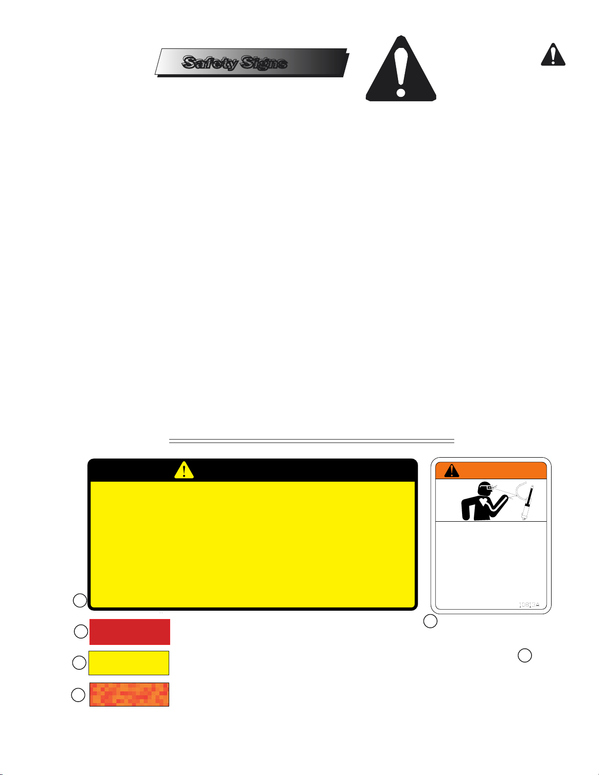
• Decals for the Extended Frame Soil Builder
are pictured below. Their locations on the
machine are shown on the next page.
CAUTION
1. DO NOT LUBRICATE, ADJUST OR REPAIR WHEN MACHINE IS IN MOTION.
2. DO NOT TOW OR TRANSPORT FASTER THAN 15 MILES PER HOUR.
3. DO NOT RIDE OR ALLOW OTHERS TO RIDE ON THE MACHINE.
4. BLOCK UP ALL HYDRAULICALLY OR MECHANICALLY RAISED COMPONENTS TO PREVENT
UNINTENDED LOWERING OR LOWER THE MACHINE TO THE GROUND TO MAKE ADJUSTMENT
OR REPAIRS OR WHEN NOT IN USE.
5. KEEP ALL PERSONS AWAY FROM MACHINE DURING HITCHING AND OPERATING.
6. SLOW DOWN BEFORE MAKING SHARP TURNS OR USING THE BRAKE.
DRIVE SLOWLY OVER ROUGH GROUND, SIDE HILLS, AND AROUND CURVES TO AVOID TIPPING.
7. COMPLY WITH ALL LAWS WHEN TRANSPORTING THE MACHINE ON PUBLIC ROADWAYS.
8. INSTRUCT ALL OPERATORS IN THE SAFE OPERATION OF THE MACHINE.
REVIEW THE OPERATOR’S MANUAL FOR CORRECT PROCEDURES.
9. BLOCK IMPLEMENT TO PREVENT MOVEMENT WHEN UNHITCHED FROM TRACTOR.
10. KEEP ALL GUARDS AND SHIELDS IN PLACE WHILE MACHINE OR PARTS ARE IN MOTION.
1
3
1. 8J310 .... Decal, Caution List
4
5
791rev5-30-05
2. 3J706 .... Decal, Warning-Hydraulic Leaks
3. 528933 .... Decal,Reflective Red
4. 528934 .... Decal, Reflective Amber
5. 528938 ... Decal, Reflective Red-Orange
6. 2P151.......SMV Sign
8J310
WARNING
WARNING
DO NOT GO NEAR LEAKS
High pressure oil easily punctures
skin causing serious injury,
gangrene or death.
If injured, seek emergency medical
help. Immediate surgery is
required to remove oil.
Do not use fingers or skin to
check for leaks.
Lower load or relieve hydraulic
pressure before loosening fittings.
2
6
1K705Page 5
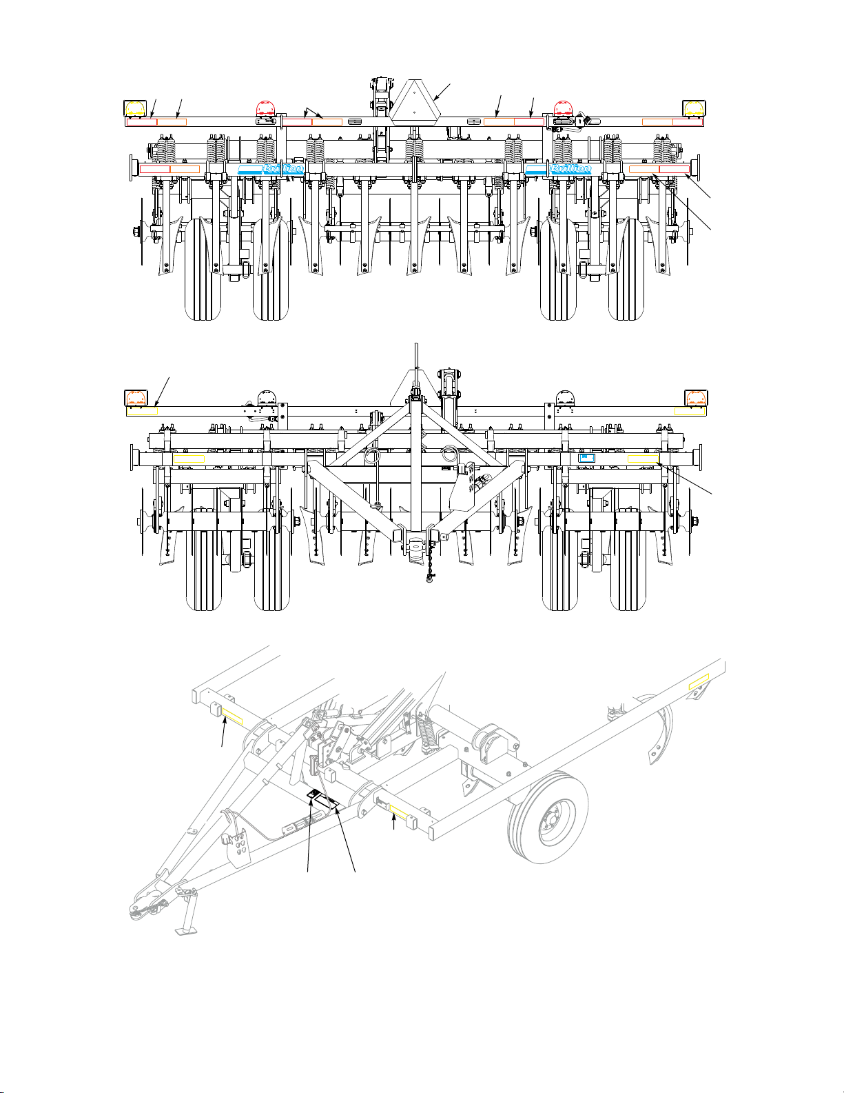
Safety Sign Locations
Center Decals
4
3
on 11 & 13 Shank
Only
6
3
4
4
3
REAR VIEW
11 & 13 SHANK
5
5
FRONT VIEW
4
4
2
1
1. 8J310 - Caution Decal
DRAWBAR and SIDE VIEW
2. 3J706 - Warning Hydraulic Leaks
3. 528938 - Orange Stripe
4. 528933 - Reflector, Red
5. 528934 - Reflector, Yellow
6. 2P151 - SMV Sign
Page 6 1K705
TRACTOR
DRAWBAR
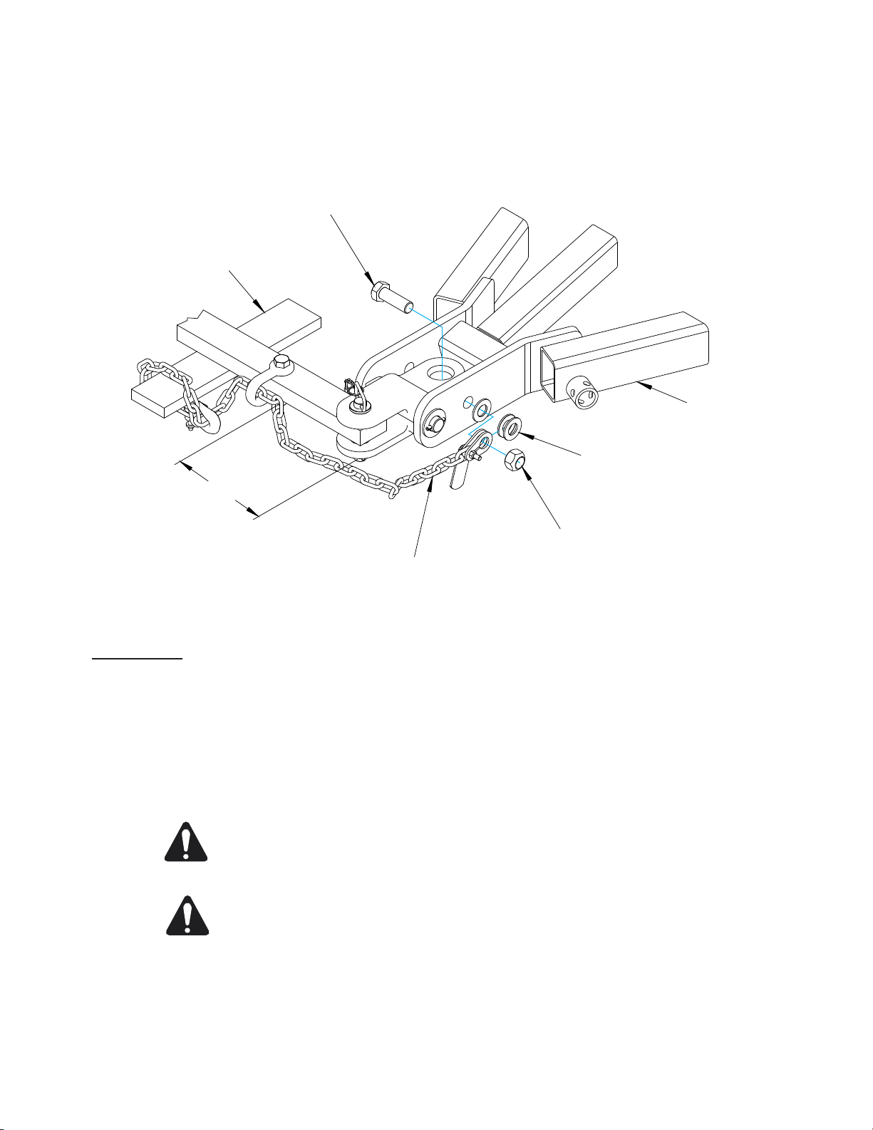
Safety Chain
Figure 3
HHCS,1-8 x 3
DRAWBAR
FLAT WASHER,1" SAE
9" MAX
NUT,LOCK 1-8
SAFETY CHAIN
Safety Chain
WFPSafetyChain
Use of a 10,100# safety chain is recommended if the machine is towed on a public road or highway.
Total weight of towed machine must not exceed chain capacity as shown on the chain’s identification
tag.
Slack in the chain should be only enough to permit turning. Distance from hitch pin to attachment
point or intermediate support should not exceed 9”.
CAUTION If two or more machines are pulled in tandem, a larger chain may be
required. Chain capacity must be greater than the total weight of towed
implements. A second chain should be used between each implement.
CAUTION Replace chain if one or more links are broken, stretched, or otherwise
damaged or deformed.
SoilBuilder SafetyChain
Keep attaching hardware fastened securely.
If bolts are replaced, be sure to use grade 5 or higher unless otherwise specif
If you have any questions regarding the safety chain call your Brillion dealer.
791rev0514
Page 7
ed.
1K705
Operation
Operation
The Brillion Soil Builder should be inspected prior
to operation to see that all nuts and bolts are
tight and to be sure that it is in good operating
condition. (After the first few hours of initial
operation, check bolts once again to be sure they
haven’t loosened.)
Hitch the coulter-chisel to the tractor drawbar. It
may be necessary to adjust the adjustable brace
rod assembly of the coulter-chisel so that the
clevis is at the proper height for tractor drawbar.
A 3½ x 16 cylinder is used to raise and lower
the machine. With the cylinder installed, attach
hydraulic hoses to the tractor hydraulic system so
the machine will be lowered when moving control
lever forward.
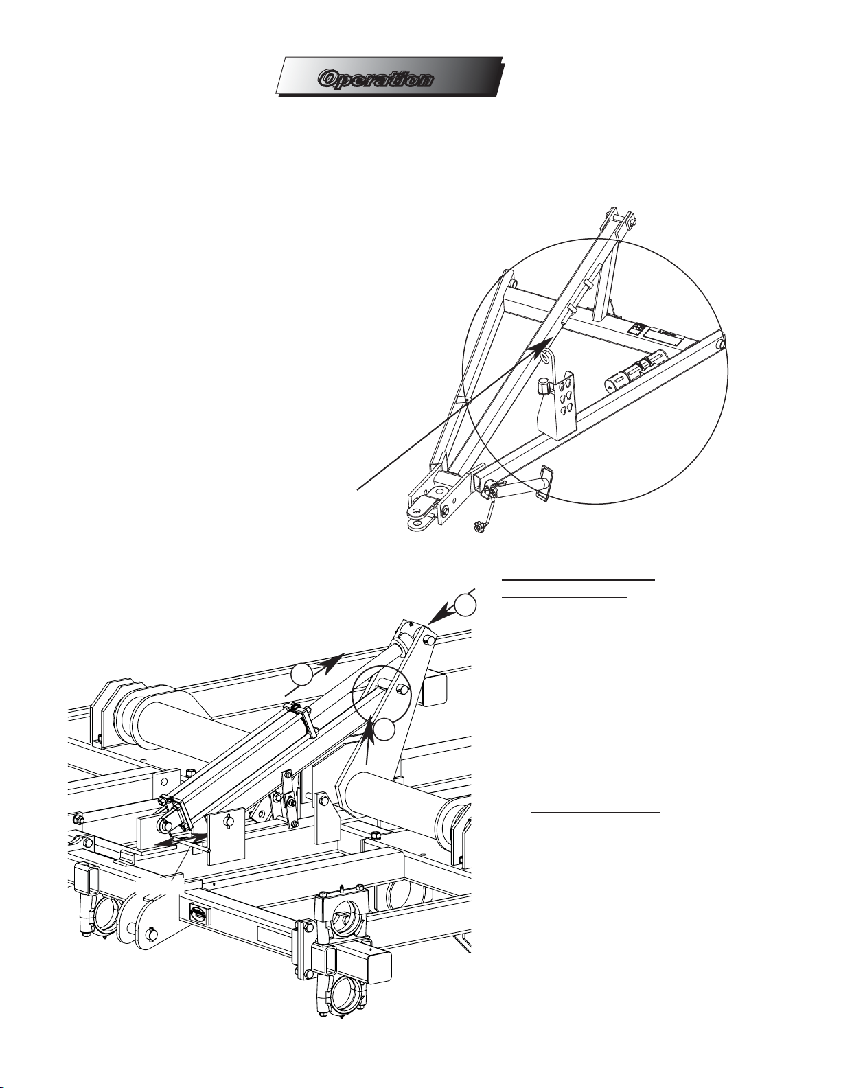
Make sure the ratchet
is stored away from the
machine raising cylinder.
IMPORTANT! Remove the handle from the
ratchet jack before raising or lowering the machine
to prevent bending the handle. Store the handle
on the drawbar.
1
2
Handle
TRANSPORTING THE
COULTER-CHISEL
3
To transport the unit, extend the
transport cylinder completely
and raise the transport lock into
position by pulling the handle to
the front and latching the handle
in place. Then retract the
cylinder until the weight is taken
up by the lock. The machine is
now ready for transport.
FIELD OPERATION
To release the transport lock,
extend the transport cylinder
full length and push the lock
handle to the rear to lower
the lock. Lower the machine
to the desired working depth.
If your cylinder is eqipped
with a depth stop, you may
set the depth by adjusting the
moveable hydraulic stop on the
cylinder rod.
791rev1-10-08
1K705Page 8
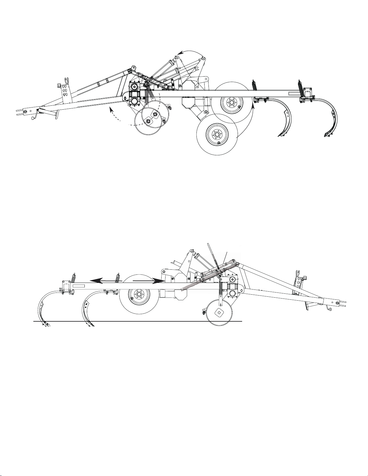
3” x 8” Cyllinder
Operates Coulters
3-1/2” x 16” Cyllinder
Operates Wheel Raising
Set the coulters to the desired depth by operating
the hydraulic cylinder on the coulter depth control
(or by moving the pins to the proper holes if your
machine is equipped with manually adjustable
coulters.)
For Field Operation, the spring bolts should
be tightened so that one inch of thread is exposed.
For chisel plowing tougher ground you may want to
clamp the spring tighter, but when this is done, the
shank and tooth will not pass over as great an obstruction.
Do not set the coulters deeper than necessary
to cut the surface residue. Setting the coulters
too deep in firm soil may prevent the shanks from
properly penetrating the soil.
Ratchet Jack
Now check to make sure the machine is level in
working position. The machine is leveled from
front to back by adjusting the ratchet jack on the
drawbar brace.
791rev1-10-08
For best results, operate tractor at 4 to 6 miles
per hour. Reduce speed when approaching the
end of the field. When turning or backing up raise
the coulter-chisel clear of the ground to prevent
damage to the shanks and disc gang assemblies.
1K705Page 9

LUBRICATION
On your Brillion Soll Builder the
following grease fittings should
be greased after each 8 hours
of operation.
The four cast bearings on the
coulter gangs, the six steel
bearings on the wheel arms
and rockshaft and the center
bearing on the rockshaft.
8
HRS.
791rev5-30-05
8
HRS.
Also the four pins on the
links from rockshaft to the
wheel arms.
Each season repack the wheel
bearings and the walking beam
pivot bearings on machines
equipped with walking beam axles.
Page 10
1K705
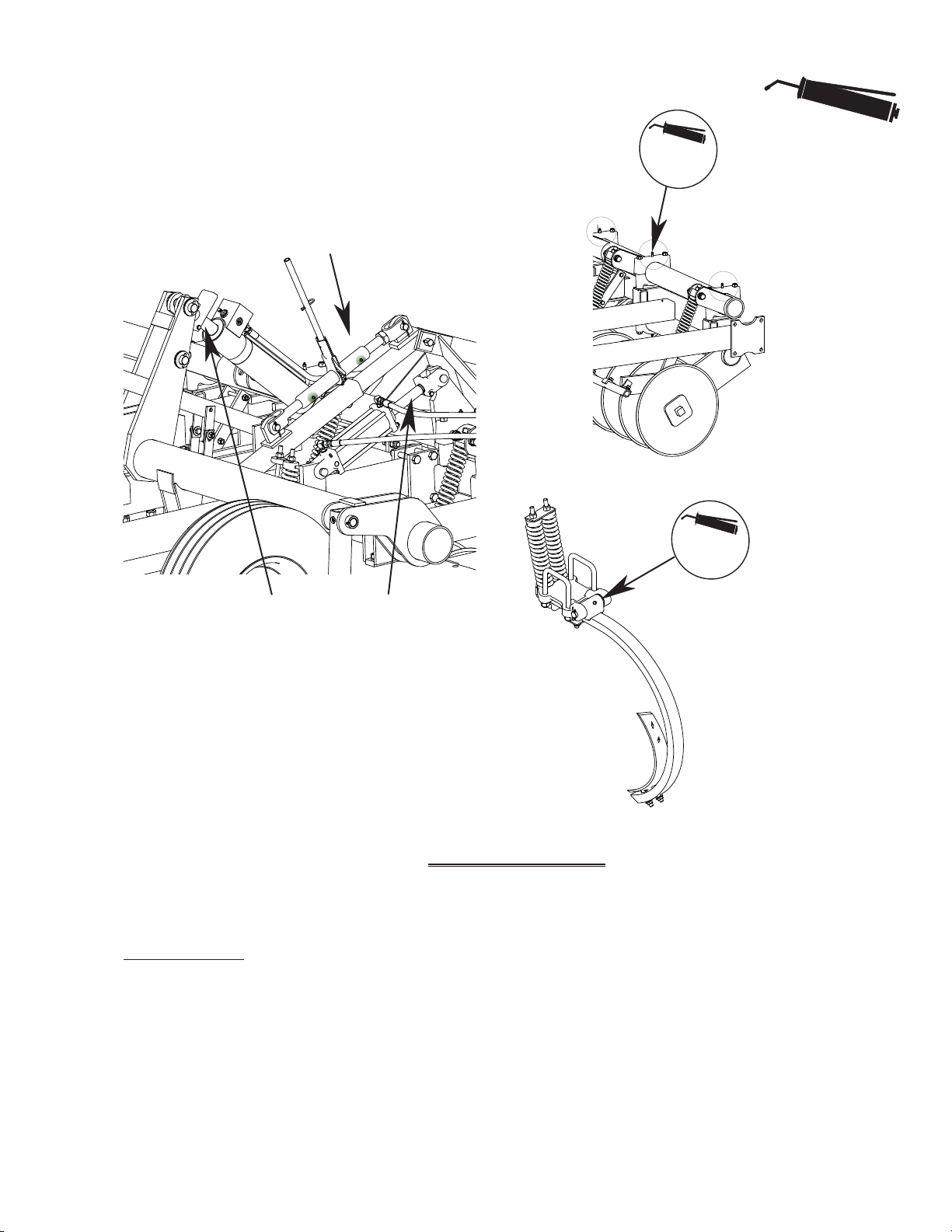
Grease the ratchet jack as
needed to prevent rusting, .
Coat the cylinder rods with grease to prevent the
rods from rusting if the machine will be stored
outside or for a prolonged period of time.
Daily
8
HRS.
If your machine
is equipped with
spring cushion
shanks, grease the
shank pivot after
each 8 hours of
operation.
On machines
equipped with
hydraulic coulter
adjustment,
grease the cast
bearings daily.
MAINTENANCE
Clean dirt, weeds, and any other foreign material
from the coulter-chisel before storing at the end of
the season. Repaint areas where paint has worn
791rev5-30-05
Page 11
off. Repair or replace any broken or damaged
parts. Store in a dry, protected place.
1K705
 Loading...