

Landoll 2211 User Manual

Model 2211
Ripoll
Operator’ s Manual
LANDOLL CORPORATION
1900 North Street
Marysville, Kansas 66508
(785) 562-5381
800-428-5655 ~ WWW.LANDOLL.COM
F-571-0613 06/2013


1 Introduction
Understanding Safety Statements . . . . . . . . . . . . . . . . . . . . . . . . . . . . . . . . . . . . . . . . . . . . . . . . 1-2
2 Standard Specifications
3 Assembly Instructions
Ripoll Frame Assembly . . . . . . . . . . . . . . . . . . . . . . . . . . . . . . . . . . . . . . . . . . . . . . . . . . . . . . . . . 3-3
2211-13/15 Ripoll Wing Extension Assembly . . . . . . . . . . . . . . . . . . . . . . . . . . . . . . . . . . . . . . . 3-5
2211-13 & -15 Fold Lock Assembly . . . . . . . . . . . . . . . . . . . . . . . . . . . . . . . . . . . . . . . . . . . . . . . 3-7
Wheel Lift Installation . . . . . . . . . . . . . . . . . . . . . . . . . . . . . . . . . . . . . . . . . . . . . . . . . . . . . . . . . . 3-9
Hitch Installation . . . . . . . . . . . . . . . . . . . . . . . . . . . . . . . . . . . . . . . . . . . . . . . . . . . . . . . . . . . . . 3-11
Depth Stop Tube Assembly . . . . . . . . . . . . . . . . . . . . . . . . . . . . . . . . . . . . . . . . . . . . . . . . . . . . 3-13
Disc Gang and Depth Adjustment Installation . . . . . . . . . . . . . . . . . . . . . . . . . . . . . . . . . . . . . 3-15
Table of Contents
Auto Reset Shank and Shovel Installation . . . . . . . . . . . . . . . . . . . . . . . . . . . . . . . . . . . . . . . . 3-19
Disc Gang Depth Gauge Assembly . . . . . . . . . . . . . . . . . . . . . . . . . . . . . . . . . . . . . . . . . . . . . . 3-21
Hydraulic Installation . . . . . . . . . . . . . . . . . . . . . . . . . . . . . . . . . . . . . . . . . . . . . . . . . . . . . . . . . . 3-25
Light Installation (Prior to August, 2013) . . . . . . . . . . . . . . . . . . . . . . . . . . . . . . . . . . . . . . . . . . 3-27
Light Installation (After August, 2013) . . . . . . . . . . . . . . . . . . . . . . . . . . . . . . . . . . . . . . . . . . . . 3-29
Final Assembly . . . . . . . . . . . . . . . . . . . . . . . . . . . . . . . . . . . . . . . . . . . . . . . . . . . . . . . . . . . . . . . 3-30
Rear Jack Installation . . . . . . . . . . . . . . . . . . . . . . . . . . . . . . . . . . . . . . . . . . . . . . . . . . . . . . . . . 3-31
Standard Tubular Mount Chopper/Conditioner Reel Installation (Option) . . . . . . . . . . . . . . . 3-33
Hydraulic Tubular Mount Chopper Reel Installation . . . . . . . . . . . . . . . . . . . . . . . . . . . . . . . . 3-38
4 Operation and Maintenance
Tractor Preparation . . . . . . . . . . . . . . . . . . . . . . . . . . . . . . . . . . . . . . . . . . . . . . . . . . . . . . . . . . . . 4-2
Ripoll Preparation . . . . . . . . . . . . . . . . . . . . . . . . . . . . . . . . . . . . . . . . . . . . . . . . . . . . . . . . . . . . . 4-2
Attaching to the Tractor . . . . . . . . . . . . . . . . . . . . . . . . . . . . . . . . . . . . . . . . . . . . . . . . . . . . . . . . 4-2
Hydraulic Lift System . . . . . . . . . . . . . . . . . . . . . . . . . . . . . . . . . . . . . . . . . . . . . . . . . . . . . . . . . . 4-3
Hydraulic Fold System (2211-13 & -15 Models Only) . . . . . . . . . . . . . . . . . . . . . . . . . . . . . . . . . 4-4
Hydraulic Disc Gang Lift System . . . . . . . . . . . . . . . . . . . . . . . . . . . . . . . . . . . . . . . . . . . . . . . . . 4-6
General Operation . . . . . . . . . . . . . . . . . . . . . . . . . . . . . . . . . . . . . . . . . . . . . . . . . . . . . . . . . . . . . 4-6
Field Operation . . . . . . . . . . . . . . . . . . . . . . . . . . . . . . . . . . . . . . . . . . . . . . . . . . . . . . . . . . . . . . . . 4-7
F-571-0613 Edition i

Leveling (Front-to-Rear) . . . . . . . . . . . . . . . . . . . . . . . . . . . . . . . . . . . . . . . . . . . . . . . . . . . . . . . . . 4-7
Variable Ratio Adjustment . . . . . . . . . . . . . . . . . . . . . . . . . . . . . . . . . . . . . . . . . . . . . . . . . . . . . . . 4-8
Disc Blades . . . . . . . . . . . . . . . . . . . . . . . . . . . . . . . . . . . . . . . . . . . . . . . . . . . . . . . . . . . . . . . . . . . 4-9
Disc Gang Angle Settings . . . . . . . . . . . . . . . . . . . . . . . . . . . . . . . . . . . . . . . . . . . . . . . . . . . . . . 4-11
Depth Stop Adjustment (Manual) . . . . . . . . . . . . . . . . . . . . . . . . . . . . . . . . . . . . . . . . . . . . . . . . 4-13
Wheel Bearing Maintenance . . . . . . . . . . . . . . . . . . . . . . . . . . . . . . . . . . . . . . . . . . . . . . . . . . . . 4-13
Hydraulic Maintenance . . . . . . . . . . . . . . . . . . . . . . . . . . . . . . . . . . . . . . . . . . . . . . . . . . . . . . . . 4-13
Transport . . . . . . . . . . . . . . . . . . . . . . . . . . . . . . . . . . . . . . . . . . . . . . . . . . . . . . . . . . . . . . . . . . . . 4-14
Lubrication Maintenance . . . . . . . . . . . . . . . . . . . . . . . . . . . . . . . . . . . . . . . . . . . . . . . . . . . . . . . 4-17
Storage . . . . . . . . . . . . . . . . . . . . . . . . . . . . . . . . . . . . . . . . . . . . . . . . . . . . . . . . . . . . . . . . . . . . . 4-17
5 Troubleshooting Guide
ii F-571-0613 Edition

Chapter 1
Introduction
The Landoll Model 2211 Ripoll is a quality product designed to give years of trouble free performance. By following
each section of this manual, your system will perform as designed for you and your operation
CHAPTER 1 gives basic instructions on the use of this manual.
CHAPTER 2 gives product specifications. These specifications supply lengths and measures for your
equipment. A S tandard Bolt Torq ue Table is provided to give guidelines for bolt to rques to
be used when servicing this product.
CHAPTER 3 contains assembly instructions for your Model 2211 Ripoll. When these procedures are
correctly followed, your equipment should provide you years of trouble-free operation
and service.
CHAPTER 4 instructs how to operate your equipment before using it, and describes adjustments
needed. It also gives practical advice for the care and maintenance of your Landoll
equipment. Drawings in this section locate adjustment points on the equipment.
NOTE: IF THE EQUIPMENT IS IMPROPERLY ASSEMBLED OR MAINTAINED, THE
WARRANTY IS VOID. IF YOU HAVE ANY QUESTIONS CONTACT:
LANDOLL CORPORATION
1900 NORTH STREET
MARYSVILLE, KANSAS 66508
or phone:
(785) 562-5381 or
(800) 428-5655
or FAX:
(888) 527-3909
CHAPTER 5 is a troubleshooting guide to aid in diagnosing and solving problems with the equipment.
PARTS LIST is a separate manual showing the various assemblies, subassemblies, and systems.
Refer to that manual when ordering Landoll replacement parts. Order parts from your
Landoll dealer.
WARRANTY The Warranty Registration form is included with the product documents. Fill it out and
mail it within 15 days of purchase.
NOTE: IMPROPER ASSEMBLY, MODIFICATION, OR MAINTENANCE OF YOUR
LANDOLL MACHINE CAN VOID YOUR WARRANTY.
COMMENTS Address comments or questions regarding this publication to:
LANDOLL CORPORATION
1900 NORTH STREET
MARYSVILLE, KANSAS 66508
ATTENTION: PUBLICATIONS -DEPT. 55
1-1

INTRODUCTION
DANGER
WARNING
CAUTION
NOTE
NOTE
Understanding Safety Statements
You will find various types of safety information on the
following pages and on the machine signs (decals)
attached to the vehicle. This section explains their
meaning.
The Safety Alert Symbol means ATTENTION! YOUR
SAFETY IS INVOLVED!
Danger means a life-threatenin g sit ua ti on ex is ts.
Death can occur if safety measures or
instructions on this label are not properly
followed.
Warning means serious injury or death can occur
if safety measures or instructions on this label
are not properly followed.
Caution means serious equipment or other
property damage can occur if instruction s on this
label are not properly followed.
Means that failure to follow these instructions could
cause damage to the equipment or cause it to operate
improperly.
Make sure you read and understand the informatio n
contained in this manual and on the machine signs
(decals) before you attempt to operate or maintain this
vehicle.
The safety statements contai ned in this manual relate to
the operation of the Model 2211 Ripoll.
1-2 F-571-0613 Edition

Standard Specifications
2211 SERIES RIPOLL
Chapter 2
NO. OF
MODEL
NO.
2211-09 11’-3” 15’-4” 6’-2” 9 15” 16/18 8 Bolt
2211-11 13’-9” 17’-1” 6’-2” 11 15” 18/20 14,410
2211-13 16’-4” 17’-9” 13’-4” 13 15” 22/24 8 Bolt
2211-15 18’-9” 18’-11” 14’-0” 15 15” 21,560
12.5L x 15
Farm Highway Service
380/55R-16.5 Goodyear Load Index 150A8/B
WORKING
WIDTH
Tire Size Tire Manufacturer Ply/Load Rating Inflation Pressure (Psi) (Max.)
TRANSPORT
WIDTH
Goodyear F Load 6000 lbs. @ 20 mph 90 psi
TRANSPORT
HEIGHT
Tire Inflation
7400 lbs @ 30 mph
NO. OF
SHANKS
SHANK
SPACING
73 psi
BLADES
F/R
TIRES AND
WHEELS
Wheels w/
2-1/4”
Spindles
Wheels w/
3” Spindles
ESTIMATED
WEIGHT
(LBS.)
13,480
20,600
2-1
STANDARD SPECIFICATIONS
LANDOLL CORPORATION
GENERAL TORQUE SPECIFICATIONS (REV. 4/97)
THIS CHART PROVIDES TIGHTENING TORQUES FOR GENERAL PURPOSE APPLICATIONS WHEN SPECIAL TORQUES ARE NOT SPECIFIED ON PROCESS
OR DRAWING.
ASSEMBLY TORQUES APPLY TO PLATED NUTS AND CAPSCREWS ASSEMBLED WITHOUT SUPPLEMENTAL LUBRICATION (AS RECEIVED CONDITION).
THEY DO NOT APPLY IF SPECIAL GRAPHITE MOLY-DISULFIDE OR OTHER EXTREME PRESSURE LUBRICANTS ARE USED.
WHEN FASTENERS ARE DRY (SOLVENT CLEANED), ADD 33% TO AS RECEIVED CONDITION TORQUE.
BOLT HEAD IDENTIFICATION MARKS INDICATE GRADE AND MAY VARY FROM MANUFACTURER TO MANUFACTURER.
THICK NUTS MUST BE USED ON GRADE 8 CAPSCREWS.
USE VALUE IN [ ] IF USING PREVAILING TORQUE NUTS.
TORQUE IS SPECIFIED IN FOOT POUNDS
UNC
Size
1/4-20 4 [5] 6 [7] 9 [11] 1/4-28 5 [6] 7 [9] 10 [12]
5/16-18 8 [10] 13 [16] 18 [22]
SAE Grade2SAE Grade5SAE Grade
8
UNF
Size
5/16-24
SAE Grade 2SAE Grade5SAE Grade
8
9[11]14[17]20[25]
3/8-16 15 [19] 23 [29] 35 [43] 3/8-24 17 [21] 25 [31] 35 [44]
7/16-14 24 [30] 35 [43] 55 [62] 7/16-20 27 [34] 40 [50] 60 [75]
1/2-13 35 [43] 55 [62] 80 [100] 1/2-20 40 [50] 65 [81] 90 [112]
9/16-12 55 [62] 80 [100] 110 [137] 9/16-18 60 [75] 90 [1 12] 130 [162]
5/8-11 75 [94] 110 [137] 170 [212] 5/8-18 85 [106] 130 [162] 180 [225]
3/4-10 130 [162] 200 [250] 280 [350] 3/4-16 150 [188] 220 [275] 320 [400]
7/8-9 125 [156] 320 [400] 460 [575] 7/8-14 140 [175] 360 [450] 500 [625]
1-8 190 [237] 408 [506] 680 [850] 1-14 210 [263] 540 [675] 760 [950]
1-1/8-7 270 [337] 600 [750] 960 [1200] 1-1/8-12 300 [375] 660 [825] 1080 [1350]
1-1/4-7 380 [475] 840 [1050] 1426 [1782] 1-1/4-12 420 [525] 920 [1150] 1500 [1875]
1-3/8-6 490 [612] 110 [1375] 1780 [2225] 1-3/8-12 560 [700] 1260 [1575] 2010 [2512]
1-1/2-6 650 [812] 1460 [1825] 2360 [2950] 1-1/2-12 730 [912] 1640 [2050] 2660 [3325]
1-3/4-5 736 [920] 1651 [2063] 2678 [3347] 1-3/4-12 920 [1150] 2063 [2579] 3347 [4183]
METRIC
COARSE THREAD METRIC CLASS 10.9 FASTENERS AND CLASS 10.0 NUTS AND THROUGH HARDENED FLAT WASHERS, PHOSPHATE COATED, ROCKWELL
“C” 38-45.
USE VALUE IN [ ] IF USING PREVAILING TORQUE NUTS.
Nominal
Thread
Diameter
mm
Standard Torque Nominal
Newton-
Meters
Foot-
Pounds
Thread
Diameter
mm
Standard Torque
Newton-
Meters
Foot-
Pounds
6 10 [14] 7 [10] 20 385 [450] 290 [335]
7 16 [22] 12 [16] 24 670 [775] 500 [625]
8 23 [32] 17 [24] 27 980 [1105] 730 [825]
10 46 [60] 34 [47] 30 1330 [1470] 990 [1090]
12 80 [101] 60 [75] 33 1790 [1950] 1340 [1450]
14 125 [155] 90 [115] 36 2325 [2515] 1730 [1870]
16 200 [240] 150 [180] 39 3010 [3210] 2240 [2380]
18 275 [330] 205 [245]
Table 2-1: General Torque Specifications
2-2 F-571-0613 Edition

STANDARD SPECIFICATIONS
LANDOLL CORPORATION
HYDRAULIC FITTING TORQUE SPECIFICATIONS
THIS CHART PROVIDES TIGHTENING TORQUES FOR HYDRAULIC FITTING APPLICATIONS WHEN SPECIAL TORQUES ARE NOT SPECIFIED ON PROCESS
OR DRAWING.
ASSEMBLY TORQUES APPLY TO PLATED CARBON STEEL AND STAINLESS STEEL FITTINGS ASSEMBLED WITHOUT SUPPLEMENTAL LUBRICATION (AS
RECEIVED CONDITION). THEY DO NOT APPLY IF SPECIAL GRAPHITE MOLY-DISULFIDE OR OTHER EXTREME PRESSURE LUBRICANTS ARE USED.
BRASS FITTINGS AND ADAPTERS - 65% OF THE TORQUE VALUE FOR STEEL. STAINLESS STEEL, ALUMINUM AND MONEL - THREADS ARE TO BE
LUBRICATED
.
TORQUE IS SPECIFIED IN FOOT POUNDS
Dash Size 37 Degree JIC O-Ring (ORS) O-Ring Boss (ORB)
-4 11-13 15-17 13-15
-5 14-16 — 21-23
-6 20-22 34-36 25-29
-8 43-47 58-62 40-44
-10 55-65 100-110 57.5-62.5
-12 80-90 134-146 75-85
-16 115-125 202-218 109-121
-20 160-180 248-272 213-237
-24 185-215 303-327 238-262
-32 250-290 — 310-340
o
37
JIC, ORS, & ORB (REV. 10/97)
PARKER BRAND FITTINGS
GATES BRAND FITTINGS
Dash Size 37 Degree JIC O-Ring (ORS) O-Ring Boss (ORB)
-4 10-11 10-12 14-16
-5 13-15 — —
-6 17-19 18-20 24-26
-8 34-38 32-40 37-44
-10 50-56 46-56 50-60
-12 70-78 65-80 75-83
-14 — 65-80 —
-16 94-104 92-105 111-125
-20 124-138 125-140 133-152
-24 156-173 150-180 156-184
-32 219-243 — —
AEROQUIP BRAND FITTINGS
Dash Size 37 Degree JIC O-Ring (ORS) O-Ring Boss (ORB)
-4 11-12 10-12 14-16
-5 15-16 — 18-20
-6 18-20 18-20 24-26
-8 38-42 32-35 50-60
-10 57-62 46-50 72-80
-12 79-87 65-70 125-135
-14 — — 160-180
-16 108-113 92-100 200-220
-20 127-133 125-140 210-280
-24 158-167 150-165 270-360
-32 245-258 — —
Table 2-2: Hydraulic Fitting Torque Specifications
2-3
STANDARD SPECIFICATIONS
182413
13
2211-09 light placement
26-3/4”
2-4 F-571-0613 Edition
Figure 2-1: Light Bracket Placement Assembly (2211-09)
STANDARD SPECIFICATIONS
182413
13
2211-11 light placement
26-3/4”
Figure 2-2: Light Bracket Plac ement Assembly (2211-11)
2-5
STANDARD SPECIFICATIONS
52
392222
8
8
2210-13 light placement
1-1/2
Figure 2-3: Light Bracket Placement Assembly (2211-13)
2-6 F-571-0613 Edition
STANDARD SPECIFICATIONS
52
392222
8
8
2210-15 light placement
1-1/2
Figure 2-4: Light Bracket Placement Assembly (2211-15)
2-7
STANDARD SPECIFICATIONS
48
22
72
20
3
3
2211-09
2211-11
12
482272
2033
12
114” REEL ASSEMBLY
91” REEL ASSEMBLY
114” REEL ASSEMBLY
82” REEL ASSEMBLY
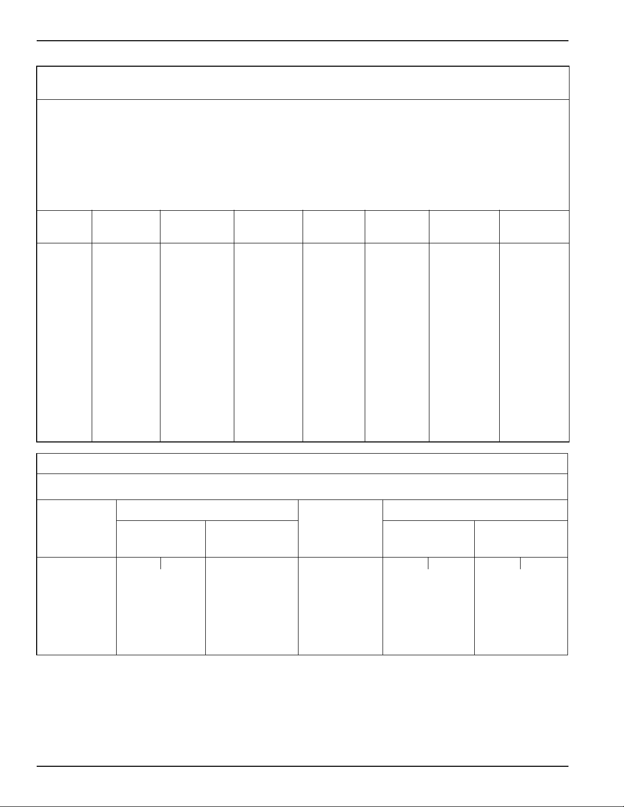
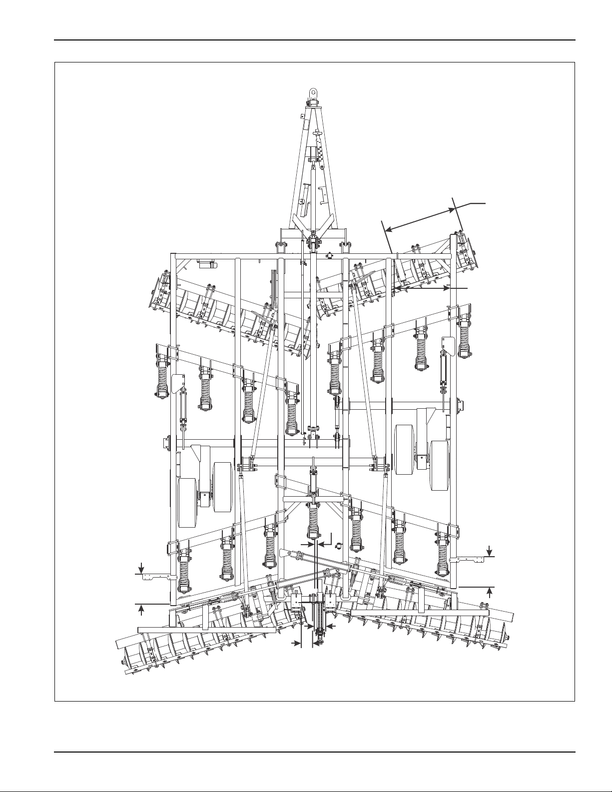
Figure 2-5: Standard and Hydraulic Tubular Mount Chopper Reel Placement (2211-09 & 2211-11)
2-8 F-571-0613 Edition

4-3/4
4-3/4
23-1/2
34-1/2 34
38-1/2
33-1/2
34
2-1/2
2-1/2
2211-13
2211-15
4-3/4
4-3/4
23-1/2
34-1/2
32
38-1/2
34
32
2-1/2
2-1/2
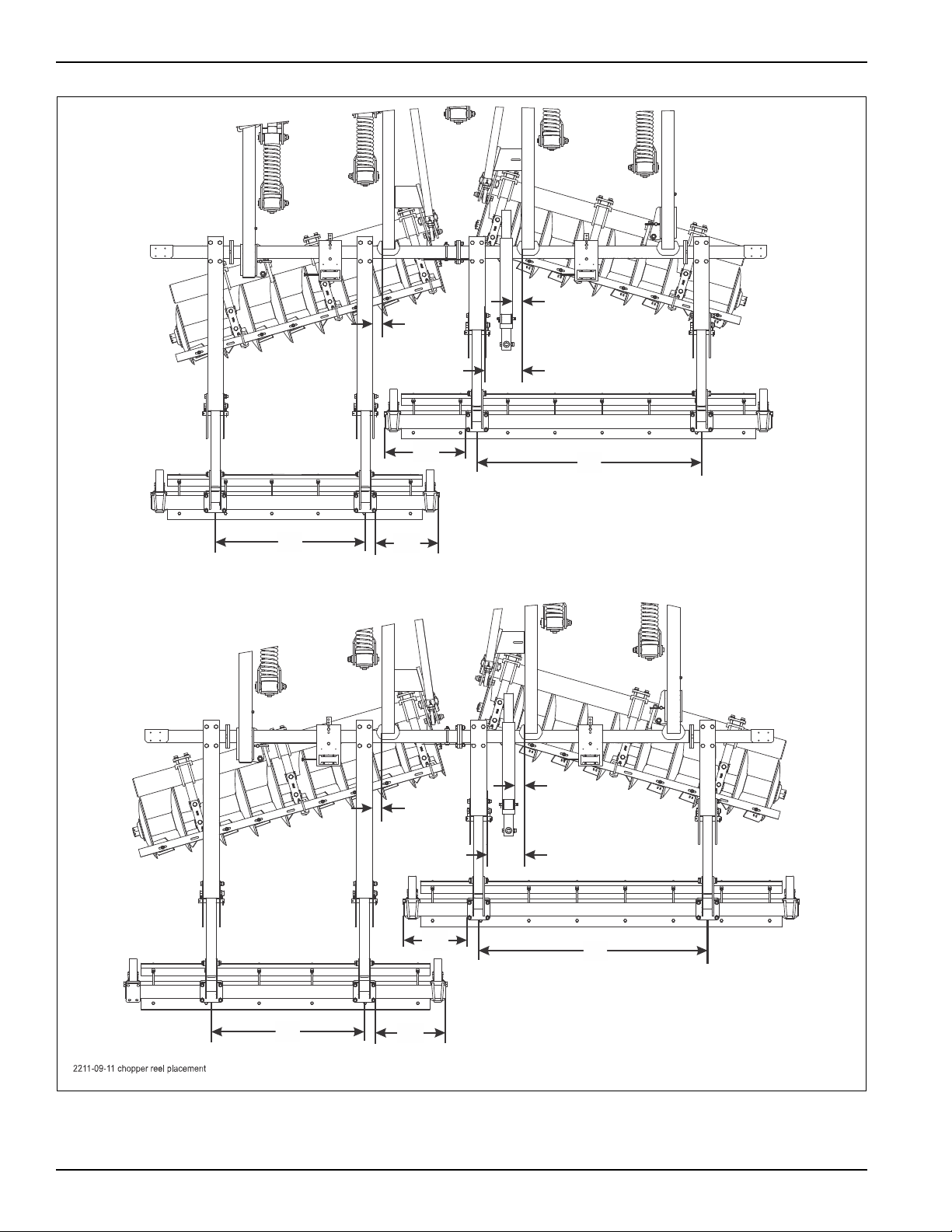
129” REEL ASSEMBLY
129” REEL ASSEMBLY
129” REEL ASSEMBLY
129” REEL ASSEMBLY
STANDARD SPECIFICATIONS
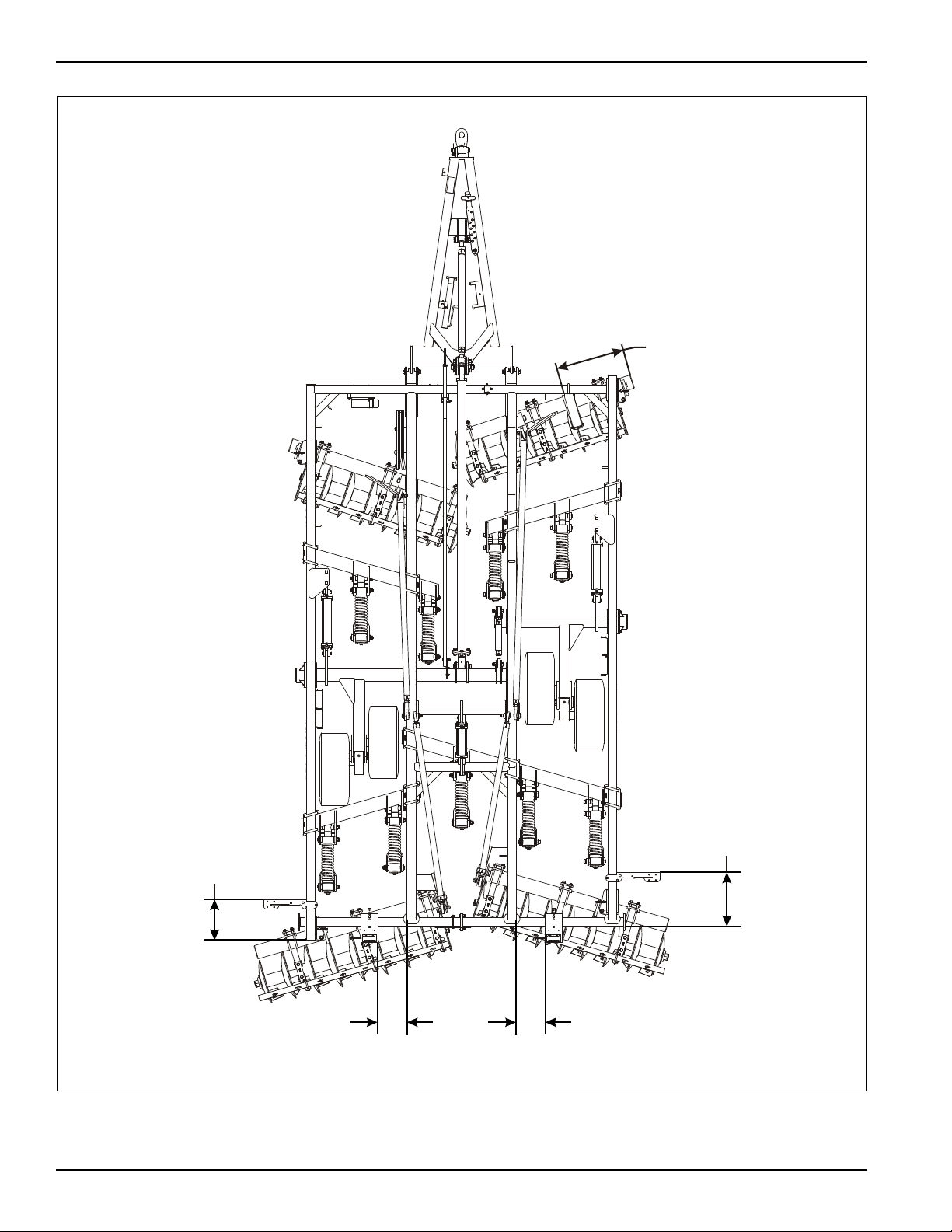
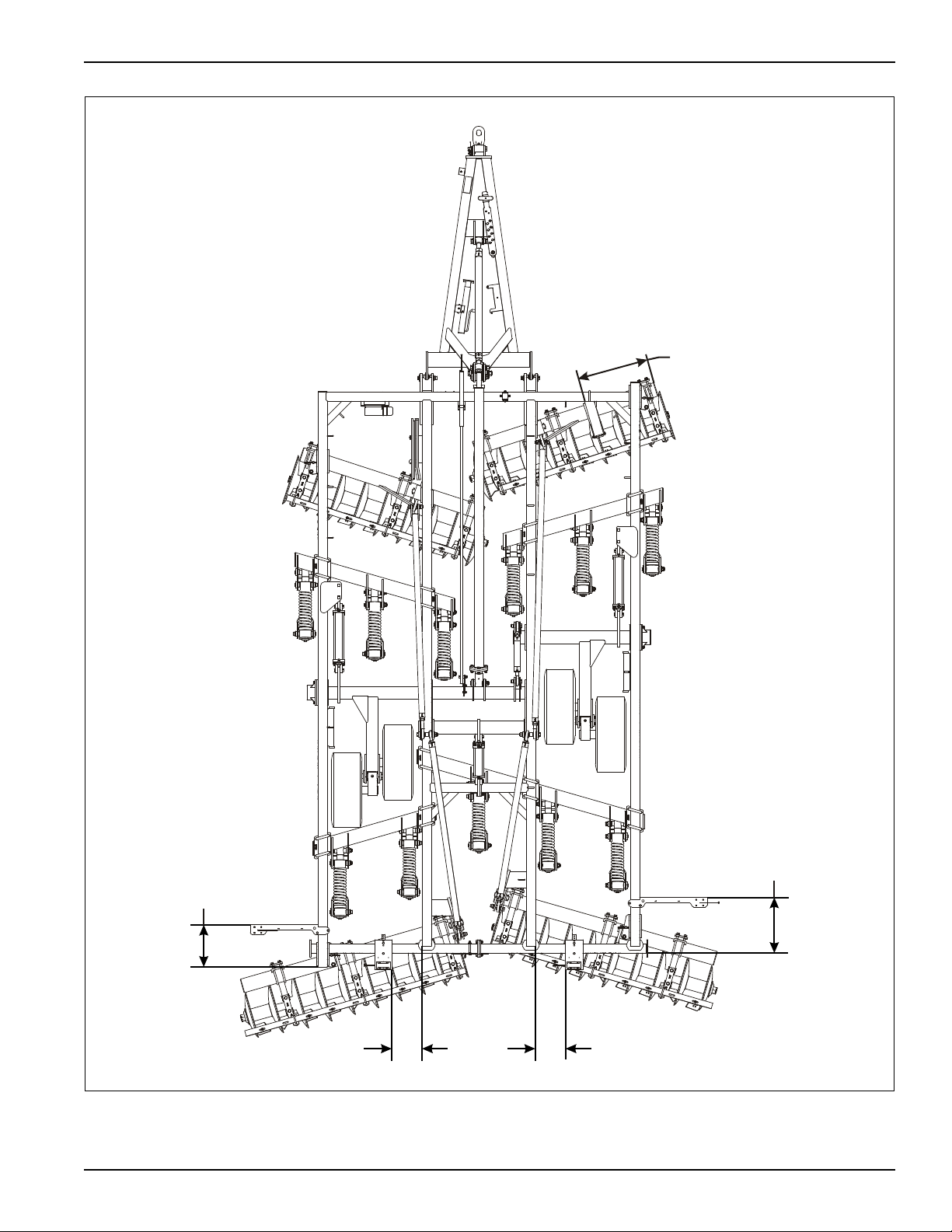
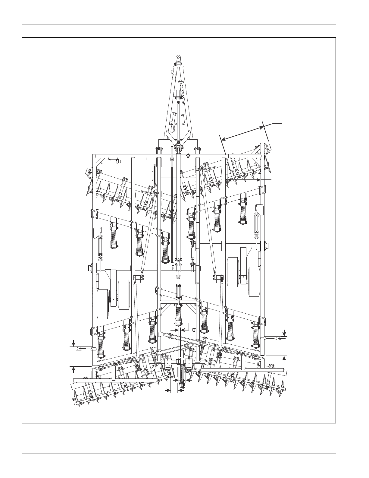
Figure 2-6: Standard and Hydraulic Tubular Mount Chopper Reel Placement (2211-13 & 2211-15)
2-9

STANDARD SPECIFICATIONS
Page Intentionally Blank
2-10 F-571-0613 Edition

It is very important that your new 2211 Ripoll be properly
DANGER
WARNING
DANGER
CAUTION
CAUTION
assembled, adjusted and lubricated before use.
Illustrations to assist with the assembly process are
provided in “Standard Specifications” on page 2-1.
They show proper shank and light mounting bracket
spacing. Illustrations in this section show proper
assembly procedures. Remove paint from grease fittings.
Replace any grease fittings that are damaged or missing.
Be sure to return screws, clips, etc., to their original
locations.
To insure alignment of assemblies, leave the nuts loose
until completion of final assembly. Use lock washers or
flat washers as specified. Spread all cotter pins.
After completion of final assembly, tighten all nuts
evenly to prevent misalignment, distortion or binding.
Tighten all screws and nut s to the recommende d torques
shown in Table 2-1.
Chapter 3
Assembly Instructions
Do not attempt to lift heavy parts (such as the
frame, disc gangs, wheel lift, and pull hitch)
manually. Use a hoist or a forklift to move these
parts into position.
To prevent accidental lowering:
1. All hydraulically elevated equipment must be
locked out using the cylinder lockouts.
2. Lower equipment to the ground while
servicing or when it is idle.
Failure to take measures to prevent accidental
lowering may result in serious personal injury or
death.
Disc blades are extremely sharp. Exercise
extreme care when working on or near disc
blades. Do not allow disc to roll over or fall onto
any body part. Do not allow wrenches to slip
when working near disc blades. Neve r pus h
wrenches toward disc blades. Do not climb over
machine above disc blades. Failure to stay clear
of disc blade edges can cause serious personal
injury or death.
Be sure to bleed the hydraulic system of a ll air in
lines after inst allation. Failure to bleed the system
of all air can result in improper machine
operation.
Incorrect adjustment of disc adjust rods will
cause permanent equipment damage.
3-1
ASSEMBLY INSTRUCTIONS
4” UHMW BEARING
LIFT BEARING CAP
RIGHT FRAME
HALF
3/4-10 HEX
LOCK NUT
LIFT BEARING
CAP
3/4-10 HEX
LOCK NUT
U-BOLT
BOTTOM
CASTING
1-8 HEX LOCK
NUT
3/4-10 X 2-1/4
HEX HEAD CAP
SCREW
TOP CASTING
LEFT FRAME
HALF
3/4-10 X 2-1/2
HEX HEAD
CAP SCREW
m2210 frame assy op
SHANK TUBE
ALIGNMENT
POINT
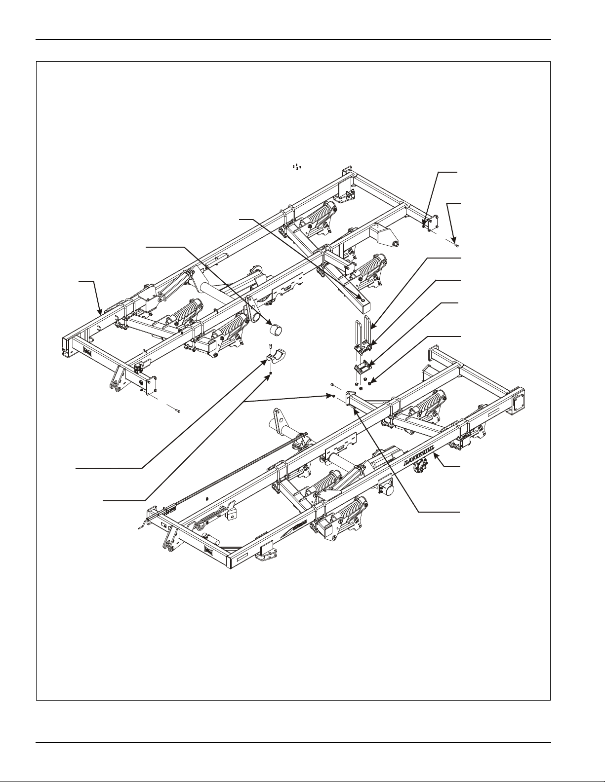
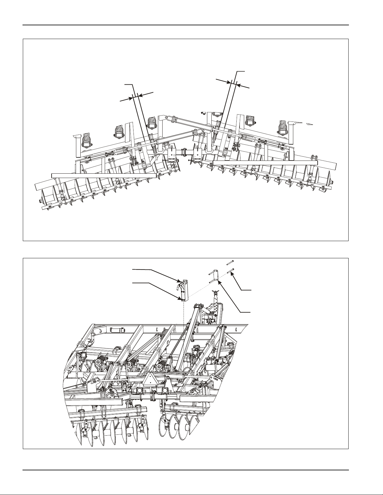
Figure 3-1: Frame and Lift Installation
3-2 F-571-0613 Edition

Ripoll Frame Assembly
IMPORT ANT
WARNING
NOTE
Read all safety precautions at the front of the section
before attempting any of the following procedures.
Do not attempt to lift heavy parts (such as the
frame, disc gangs, wheel lift, and pull hitch)
manually. Use a hoist or a forklift to move these
parts into position.
1. Place both frame halves on stands approximately 36”
high. The assembly area should be a large level area
of sufficient size to accommodate the Ripoll when
fully assembled.
2. Insert top casting (p/n 150167) onto shank tube
alignment point with other point under the frame
when fully assembled. Note that top and bottom
castings have p/n cast on them (See Figure 3-1.)
ASSEMBLY INSTRUCTIONS
It may be necessary to loosen the screws holding the lift
on the left frame half when attaching casting to the shank
tube.
3. Align both the shank tube and rockshaft in position.
This will also line up the plate on each end of the
frame.
4. Bolt frame halves together using 3/4-10 x 2-1/4 hex
head cap screws and hex lock nuts in the front and
rear plates. Bolt frame halves together using 3/4-10 x
2-1/2 hex head cap screws and hex lock nuts in the
center cylinder mount plate. Leave all screws loose.
5. Install the 1" u-bolts over the frame and through the
top casting holding the shank tube, bottom casting
(p/n 150168) and hex lock nuts.
6. Install the 4" UHMW bearing onto the left lift.
7. Connect lift bearing cap to right frame using 3/4-10 x
2 hex head cap screws and hex lock nuts.
8. Level the frame halves.
9. Tighten all hardware to the recommended torques
shown in Table 2-1.
3-3
ASSEMBLY INSTRUCTIONS
2211-15 frame and wing op
WING LATCH
PIN AND
SNAP RING
FLANGE
BEARING
HINGE EAR
PLATES
WING LATCH
HOOK
FRAME
ASSEMBLY
4 X 30 HYDRAULIC
CYLINDER
FOLD PIN
5/16 X 2-1/2
SPRING
SLOTTED PIN
1-8 X 11 HEX
HEAD CAP
SCREW
FOLD
ANCHOR
1-8 HEX LOCK
NUT
1/2 x 2-1/4 GROOVED
ALLOY PIN
FOLD ANCHOR
MOUNT PLATE
3/4-10 X 3 HEX HEAD CAP SCREW
(DO NOT OVERTIGHTEN)
HOOK LATCH ASSEMBLY
3/4-10 HEX LOCK NUT
1-1/4N FLAT WASHER
THRUST
WASHER
HITCH PIN
FOLD ANCHOR
PLATE
LH WING
1-8 HEX LOCK
NUT
3-4 F-571-0613 Edition
Figure 3-2: Wing Extension Installation (2211-13 & -15)

ASSEMBLY INSTRUCTIONS
IMPORT ANT
WARNING
NOTE
NOTE
221 1-13/15 Ripoll Wing Extension Assembly
Read all safety precautions at the front of the section
before attempting any of the following procedures.
Do not attempt to lift heavy parts (such as the
frame, disc gangs, wheel lift, and pull hitch)
manually. Use a hoist or a forklift to move these
parts into position.
1. Insert flange bearings into hinge ear plates on the
rear of frame.
2. Assemble wing latch pin to LH wing using snap ring.
The wing latch hook will hook on wing latch pin when
the wings are unfolded.
3. Assemble LH and RH wings to the hinge ear plates
on the rear of the frame using hitch pins, 1/2 x 2-1/4
grooved alloy pins, thrust washer, and 1-8 hex lock
nut (See Figure 3-2.)
Thrust washers are located in between hinge ear plates
of wing on the front side of both front and rear hinges.
4. Assemble fold anchor to fold anchor mount plates on
the frame using 1-8 x 1 1 hex head cap screw and hex
lock nut.
5. Put 4 x 30 hydraulic cylinder on top of fold anchor
with rod in between wing fold anchor plates.
6. Connect base end of 4 x 30 hydraulic cylinder to fold
anchor using fold pin and 5/16 x 2-1/2 spring slotted
pin.
7. Connect hook latch end of hook latch assembly to
wing latch hook using 3/4-10 x 3 hex head cap screw
and hex lock nut.
Do not overtighten as wing latch hook must move freely.
8. Connect rod end of 4 x 30 hydraulic cylinder to hook
latch assembly and wing through slots in the fold
anchor plates using fold pin and 5/16 x 2-1/2 spring
slotted pin.
9. Tighten all hardware to the recommended torques
shown in Table 2-1.
3-5
ASSEMBLY INSTRUCTIONS
4-3/4”
4-3/4”
2211-15 fold lock placement
3/4-10 X 13 HEX
HEAD CAP SCREW
MOUNT PLATE
FOLD LOCK ASSEMBLY
3/4-10 HEX LOCK NUT
2211-15 fold lock
Figure 3-3: Fold Lock Placement
3-6 F-571-0613 Edition
Figure 3-4: Fold Lock Assembly

2211-13 & -15 Fold Lock
IMPORT ANT
IMPORT ANT
Assembly
1. Place fold lock assembly on the front side of the 7 x 4
rear frame tube and mount plate on the back side of
the rear frame tube (See Figure 3-3.)
The placement dimensions are an approximation and
may need to be adjusted for proper alignment of
wing fold safety pin.
2. Install 3/4-10 x 13 hex head cap screws and lock
nuts to hold the fold lock and mount plate in place.
Do not tighten screws (See Figure 3-4.)
Fold wing until proper fit is achieved prior to
tightening screws.
3. Fold wings over. Adjust fold lock assembly location if
necessary. Tighten screws after proper fit is
achieved.
4. Adjust fold anchor (base of fold cylinder) as
necessary to allow wing fold lock pin to work freely.
Do not over-adjust as this could damage the cylinder
rod by forcing the wing to fold over too far.
ASSEMBLY INSTRUCTIONS
3-7
ASSEMBLY INSTRUCTIONS
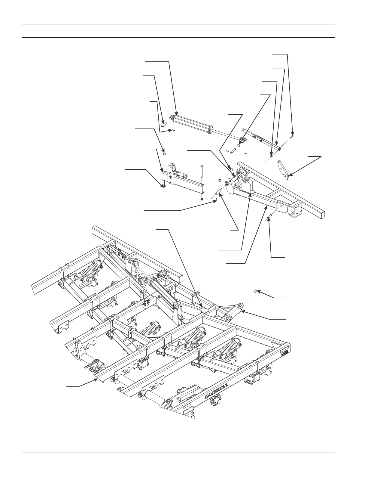
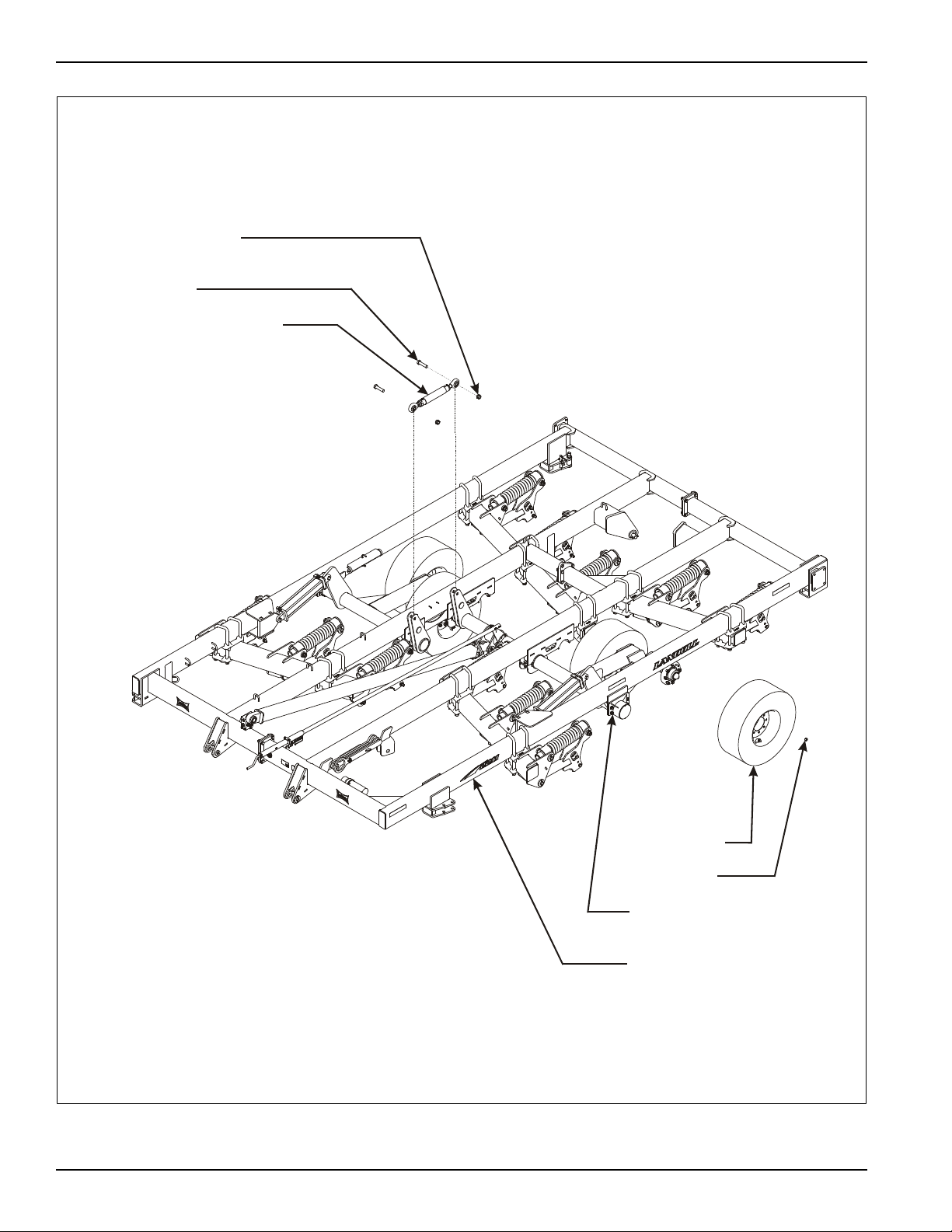
TIRE AND
WHEEL
ASSEMBLY
WHEEL LIFT
ASSEMBLY
FRAME ASSEMBL Y
LUG NUT
m2211 wheel lift assy op
1-8 HEX LOCK NUT
1-8 X 4 HEX HEAD
CAP SCREW
RADIUS ROD ASSEMBLY
3-8 F-571-0613 Edition
Figure 3-5: Wheel Lift Installation
 Loading...