

Page 1
LANCOM Antenna
AirLancer ON-D9a
Page 2
MOUNTING INSTRUCTIONS
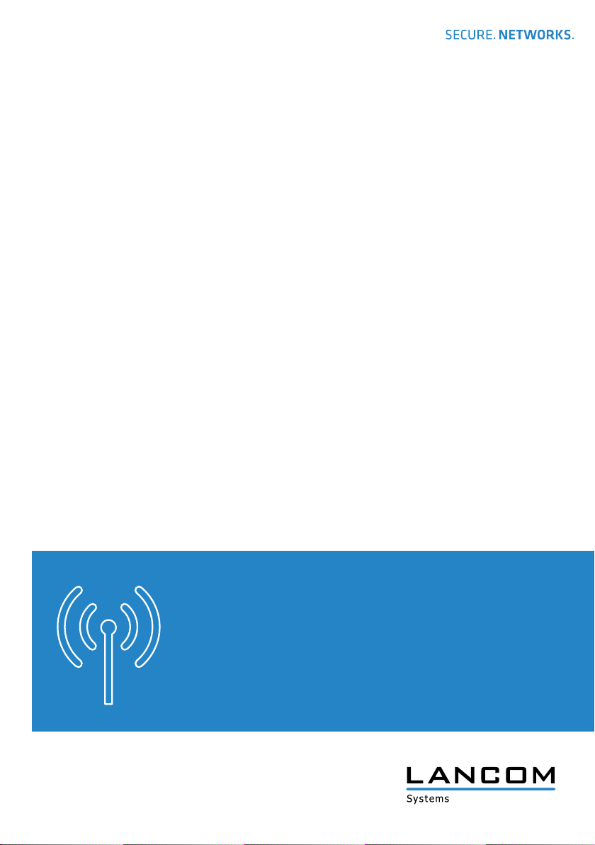
Mounting preparation
Fix the mounting bracket (antenna) to the corresponding
mounting bolts for 0° or 45° orientation at the backside
of the antenna using a hex nut, a flat washer, and a lock
washer per bolt as shown in the diagram.
Connect the mounting bracket (antenna) and the mounting
bracket (middle) using two screws plugged from the inner
side of the brackets. Fasten the connection by first placing a
flat washer and then a lock washer on each bolt. Attach the
hex nuts to the bolts and tighten the nuts hand-tight. Then
proceed with wall- or pole-mounting the antenna.
Mounting bolt
DRAIN HOLES
Mounting bracket
(antenna)
Mounting bolt
Mounting bolt
DRAIN HOLES
Mounting bracket
(middle)
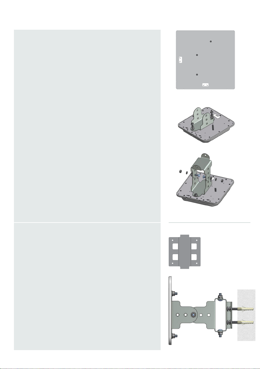
Wall mounting
Fix the mounting bracket (wall/pole) to a wall able to take
weight using the four supplied screws and dowels. Then
connect the mounting bracket (wall/pole) and the mounting
bracket (middle) of the previously mounted unit using two
screws plugged from the inner side of the brackets. Make
sure that the drain holes on the backside of the antenna
point downwards. Fasten the connection by first placing a
flat washer and then a lock washer on each bolt. Attach the
hex nuts to the bolts and tighten the nuts hand-tight.
Align the antenna according to your needs and tighten all
nuts firmly.
Mounting bracket
(wall/pole)
Mounting bracket
(middle)
Mounting bracket
(antenna)
Mounting bracket
(wall/pole)
Page 3

MOUNTING INSTRUCTIONS
Pole mounting
Fix the mounting bracket (wall/pole) to a suitable pole
(Ø 4,2 cm - 5,8 cm) using the two supplied screw clamps.
Then connect the mounting bracket (wall/pole) and the
mounting bracket (middle) of the previously mounted unit
using two screws plug+ged from the inner side of the
brackets. Make sure that the drain holes on the backside
of the antenna point downwards. Fasten the connection by
first placing a flat washer and then a lock washer on each
bolt. Attach the hex nuts to the bolts and tighten the nuts
hand-tight. Align the antenna according to your needs and
tighten all nuts firmly.
Mounting bracket
(wall/pole)
Connecting to the access point
Antennas of the AirLancer ON-D9a model feature two
antenna connectors for the parallel transmission of two data
streams in combination with a LANCOM 802.11n / 802.11ac
MIMO Access Point. In this case, the following description
applies to each of the antenna connectors. Concerning
overvoltage protection, we strongly recommend the use of
the AirLancer SN-ANT (not included). When connecting to
an Access Point, first connect one end of the supplied cable
to the AirLancer SN-ANT. Then connect the other end to
the Access Point‘s antenna output. For connection to the
antenna, first connect the end of the antenna cable to the
AirLancer SN-ANT. Then connect the other end of the antenna cable to the antenna‘s input. You may require an adapter
or adapter cable depending on the type of connector.
Page 4

MOUNTING INSTRUCTIONS
Important
Working responsibly with high frequencies
The AirLancer ON-D9a meets the requirements of the R&TT directives EN62479 and the FCC regulations. To ensure compliance with these requirements, an adequate safety distance must be maintained between the antenna and the human body when operating the antenna.
Important
Electrical and electronic equipment law
In the interests of recycling, please do not dispose of electrical and electronic waste in your household garbage. Ensure that your electrical and electronic waste is disposed of in accordance with the
regulations in your country.
Important
Proper handling of antenna cables
Antenna cables are sensitive RF cables. During installation it is important that the cables are not
creased, and bent as little as possible, otherwise the antenna will suffer a loss in performance. Do
not coil the antenna cable in tight loops.
Important
Antenna gain and terminating unused antenna connectors on the access point
It is essential to terminate unused antenna connectors on the access point with the supplied rod
antenna. The terminating resistor supplied with the adapter AirLancer AN-RPSMA-NJ is suitable for
use with indoor access points. In addition, you must disable the unused antenna connectors in LCOS
(changing the antenna grouping of the respective WLAN module), and configure the antenna gain of
the antenna. The settings can be found in LANconfig at:
Configuration > Wireless LAN > General > Physical WLAN settings > Radio
Page 5

Technical details
0
30
60
90
120
150
180
210
240
270
300
330
Port 1 - H-Plane
5000 Mhz
5300 Mhz
5800 Mhz
0
30
60
90
120
150
180
210
240
270
300
330
Port 1 - E-Plane
5000 Mhz
5300 Mhz
5800 Mhz
Frequency range 4900 - 5900 MHz
Antenna characteristics
Radiation characteristics
horizontal 9°
vertical 9°
Recommended use Point-to-Point
VSWR 1.5:1 typ. / 2.0:1 max.
Gain 23 dbi
Mechanical details
Size 340 x 340 x 30 mm (length x width x height)
Weight 1.6 kg (antenna without mounting kit)
Temperature range -40°C to 80°C
Color light grey
Material UV-resistant plastic
Mounting options Wall and pole mounting, adjustable
Cables, connectors 2x 50cm N-female-to-N-male adapter, 2x N-Female connector
Item
Warranty 2 years for AirLancer and accessories
Item number 61244
Package content Antenna, wall- and pole-mount accessories, Quick Reference Guide
5 GHz h-plane
30
20
10
0
-10
-20
-30
-40
5000 MHz
5300 MHz
5800 MHz
5 GHz e-plane
30
20
10
0
-10
-20
-30
-40
LANCOM, LANCOM Systems and LCOS are registered trademarks. All other names or descriptions used may be trademarks or registered trademarks of their
owners. Subject to change without notice. No liability for technical errors and/or omissions. 111425/1116
 Loading...