

Page 1

...connecting your business
LANCOM OAP-54 Wireless
LANCOM OAP-310agn Wireless
쮿
Handbuch
쮿
Manual
Page 2

LANCOM OAP-54 Wireless
LANCOM OAP-310agn Wireless
Page 3

© 2009 LANCOM Systems GmbH, Wuerselen (Germany). All rights reserved.
0
0909
While the information in this manual has been compiled with great care, it may not be deemed an assurance of product
characteristics. LANCOM Systems shall be liable only to the degree specified in the terms of sale and delivery.
The reproduction and distribution of the documentation and software supplied with this product and the use of its contents
is subject to written authorization from LANCOM Systems. We reserve the right to make any alterations that arise as the
result of technical development.
Windows®, Windows Vista™, Windows NT® and Microsoft® are registered trademarks of Microsoft, Corp.
The LANCOM Systems logo, LCOS and the name LANCOM are registered trademarks of LANCOM Systems GmbH. All other
names or descriptions used may be trademarks or registered trademarks of their owners.
Subject to change without notice. No liability for technical errors or omissions.
Products from LANCOM Systems include software developed by the OpenSSL Project for use in the OpenSSL Toolkit (http:/
/www.openssl.org/).
Products from LANCOM Systems include cryptographic software written by Eric Young (eay@cryptsoft.com
Products from LANCOM Systems include software developed by the NetBSD Foundation, Inc. and its contributors.
Products from LANCOM Systems contain the LZMA SDK developed by Igor Pavlov.
LANCOM Systems GmbH
Adenauerstr. 20/B2
52146 Wuerselen
Germany
www.lancom.eu
).
Wuerselen, September 2009
11
754/
Page 4

Preface
LANCOM OAP-54 Wireless and LANCOM OAP-310agn Wireless
Preface
Thank you for placing your trust in this
The LANCOM OAP Wireless are designed to offer high-performance wireless
LAN in tough environments.
The housing that conforms with IP66 and the facilities for sturdy mounting on
walls or poles all make the LANCOM OAP-54 Wireless ideally suited for locations where the demands on stability and robustness are at their highest.
Depending on the model equipped with an integrated heating and cooling the
devices enable operation in temperatures from -30° to +70°C (LANCOM
OAP-54 Wireless) and -30° to +65°C (LANCOM OAP-310agn Wireless)
respectively.
With the integrated 54/108 Mbps WLAN module according to IEEE 802.11a/
h or IEEE 802.11b/g the LANCOM OAP-54 Wireless work in the 2,4 or 5 GHz
frequency range. The LANCOM OAP-54 Wireless comes with two WLAN
modules and hence can work in both frequency ranges simultaneously.
The LANCOM OAP-310agn Wireless additionally supports the standard IEEE
802.11n and offers a maximum WLAN performance with up to 300 Mpbs.
MIMO (multiple input multiple output) technology allows the LANCOM OAP310agn Wireless to transfer several data streams in parallel and thus significantly improve data throughput.
The modells of the LANCOM OAP Wireless series can be configured in standalone, managed and client mode. In managed mode, the access point can be
securely managed by the LANCOM WLAN Controller.
LANCOM Systems
product.
EN
Model
restrictions
Model variants
This documentation is intended for LANCOM OAP Wireless users. The
following models are available:
The LANCOM OAP-54 Wireless with two integrated WLAN modules.
The LANCOM OAP-310agn Wireless with support for IEEE 802.11n stan-
dard and connectors for up to three antennas.
Passages applying only to certain models are identified either in the text itself
or by a comment in the margin.
Otherwise the documentation refers to all models collectively as the LANCOM
OAP Wireless series.
3
Page 5

LANCOM OAP-54 Wireless and LANCOM OAP-310agn Wireless
Preface
Security settings
To maximize the security available from your product, we recommend that you
undertake all of the security settings (e.g. firewall, encryption, access protection) that were not already activated when you purchased the product. The
LANconfig Wizard 'Security Settings' will help you with this task. Further information is also available in the chapter 'Security settings'.
We would additionally like to ask you to refer to our Internet site
EN
www.lancom.eu
for the latest information about your product and technical
developments, and also to download our latest software versions.
Components of the documentation
The documentation of your device consists of the following parts:
Installation Guide
User manual
Reference manual
Menu Reference Guide
You are now reading the user manual. It contains all information you need to
put your device into operation. It also contains all of the important technical
specifications.
The Reference Manual is to be found as an Acrobat document (PDF file) at
www.lancom.eu/download
or on the CD supplied. It is designed as a supplement to the user manual and goes into detail on topics that apply to a variety
of models. These include, for example:
The system design of the operating system LCOS
Configuration
Management
Diagnosis
Security
Routing and WAN functions
Firewall
Quality of Service (QoS)
Virtual Private Networks (VPN)
Virtual Local Networks (VLAN)
Wireless networks (WLAN)
Backup solutions
4
Page 6

LANCOM OAP-54 Wireless and LANCOM OAP-310agn Wireless
Preface
Further server services (DHCP, DNS, charge management)
The Menu Reference Guide (also available at www.lancom.eu/download
the CD supplied) describes all of the parameters in LCOS, the operating system
used by LANCOM products. This guide is an aid to users during the configuration of devices by means of WEBconfig or the telnet console.
This documentation was created by …
... several members of our staff from a variety of departments in order to
ensure you the best possible support when using your
Should you find any errors, or if you would like to suggest improvements, please do not hesitate to send an e-mail directly to:
info@lancom.de
Our online services www.lancom.eu are available to you around the
clock if you have any questions on the content in this manual, or if you
require any further support. The area 'Support' will help you with
many answers to frequently asked questions (FAQs). Furthermore, the
knowledgebase offers you a large reserve of information. The latest
drivers, firmware, utilities and documentation are constantly available
for download.
In addition, LANCOM Support is available. For telephone numbers
and contact addresses for LANCOM Support, please refer to the enclosed leaflet or the LANCOM Systems Web site.
LANCOM
or on
product.
EN
Information symbols
Very important instructions. Failure to observe these may result in damage.
Important instruction that should be observed.
Additional information that may be helpful but is not essential.
5
Page 7

LANCOM OAP-54 Wireless and LANCOM OAP-310agn Wireless
Content
Content
1 Introduction 9
1.1 What is a wireless LAN? 9
1.1.1 Modes of operation of wireless LANs and access points
10
1.2 Wireless LANs in accordance with 802.11n 10
EN
2 Installation 23
1.2.1 Advantages of 802.11n 10
1.2.2 Compatibility with other standards 11
1.2.3 The physical layer 12
1.2.4 The MAC layer 18
1.3 Just what can your LANCOM Wireless Router do? 20
2.1 Package contents 23
2.2 System requirements 23
2.2.1 Configuring the LANCOM devices 23
2.2.2 Operating access points in managed mode 24
2.3 Status displays and interfaces 24
2.3.1 LEDs of LANCOM OAP-54 Wireless and LANCOM OAP310agn Wireless 24
2.4 The device connectors 27
2.5 Mounting and connectiong the LANCOM OAP-54 Wireless and
LANCOM OAP-310agn Wireless 30
2.6 Software installation 34
2.6.1 Starting the software setup 34
2.6.2 Which software should I install? 35
3 Basic configuration 36
3.1 Details you will need 36
3.1.1 TCP/IP settings 37
3.1.2 Configuration protection 38
3.1.3 Settings for the wireless LAN 39
3.2 Instructions for LANconfig 40
3.3 Instructions for WEBconfig 41
3.4 TCP/IP settings for PC workstations 45
6
Page 8

LANCOM OAP-54 Wireless and LANCOM OAP-310agn Wireless
Content
4 Security settings 47
4.1 Security in the wireless LAN 47
4.1.1 Encrypted data transfer (802.11i/WPA or WEP) 47
4.1.2 802.1x / EAP 48
4.1.3 LANCOM Enhanced Passphrase Security 48
4.1.4 Access control by MAC address 49
4.1.5 IPSec over WLAN 49
4.2 Tips for the proper treatment of keys and passphrases 50
4.3 Security settings Wizard 50
4.3.1 LANconfig Wizard 51
4.3.2 WEBconfig Wizard 52
4.4 The security checklist 52
5 Advanced wireless LAN configuration 57
5.1 WLAN configuration with the wizards in LANconfig 57
5.2 Special wireless LAN parameters for 802.11n 59
5.2.1 Compatibility 59
5.2.2 Performance settings for the wireless LAN module 59
5.2.3 Performance settings for wireless LAN networks 60
5.2.4 Configuring 802.11n parameters 62
5.3 Point-to-point connections 63
5.3.1 Geometric dimensioning of outdoor wireless network
links 64
5.3.2 Antenna alignment for P2P operations 68
5.3.3 Measuring wireless bridges 70
5.3.4 Activating the point-to- point operation mode 70
5.3.5 Configuration of P2P connections 71
5.3.6 Access points in relay mode 74
5.3.7 Security for point-to- point connections 75
5.4 Client mode 76
5.4.1 Client settings 77
5.4.2 Set the SSID of the available networks 78
5.4.3 Encryption settings 78
EN
7
Page 9

LANCOM OAP-54 Wireless and LANCOM OAP-310agn Wireless
Content
6 Setting up Internet access 80
6.1 The Internet Connection Wizard 81
6.1.1 Instructions for LANconfig 81
6.1.2 Instructions for WEBconfig 81
6.2 The Firewall Wizard 82
6.2.1 LANconfig Wizard 82
6.2.2 Configuration under WEBconfig 83
EN
7 Options and accessories 84
7.1 Optional AirLancer Extender antennas 84
7.1.1 Antenna diversity 84
7.1.2 Polarization diversity 85
7.1.3 MIMO 85
7.1.4 Installing the AirLancer Extender antennas 85
7.2 LANCOM Public Spot Option 87
7.3 LANCOM VPN Option 89
8 Advice & assistance 90
8.1 No WAN connection can be established 90
8.2 Slow DSL transmission 90
8.3 Unwanted connections under Windows XP 91
9 Appendix 92
9.1 Performance data and specifications 92
9.2 Connector wiring 93
9.2.1 Ethernet interface 10/100Base-TX, DSL interface 93
9.3 CE-declarations of conformity 93
10 Index 94
8
Page 10

LANCOM OAP-54 Wireless and LANCOM OAP-310agn Wireless
Chapter 1: Introduction
1Introduction
1.1 What is a wireless LAN?
The following sections describe the functionality of wireless networks
in general. You can see from the table 'What your LANCOM can do'
further below which functions your device supports. Please refer to
the reference manual for further information on this topic.
A wireless LAN connects individual end-user devices (PCs and mobile computers) to form a local network (also called – Local Area Network). In contrast
to a traditional LAN, communication takes place over a wireless connection
and not over network cables. For this reason it is called a Wireless Local Area
Network (WLAN).
A wireless LAN provides the same functionality as a cable-based network:
Access to files, servers, printers etc. as well as the integration of individual
work stations into a corporate mail system or access to the Internet.
There are obvious advantages to wireless LANs: Notebooks and PCs can be
installed where they are needed—problems with missing connections or
structural changes are a thing of the past with wireless networks.
Apart from that, wireless LANs can also be used for connections over longer
distances. Expensive leased lines and the associated construction measures
can be saved.
EN
LANCOM Wireless Routers and LANCOM Access Points can be opera-
ted either as self-sufficient Access Points with their own configuration
(WLAN modules in "Access Point mode“) or as components in a WLAN
infrastructure, which is controlled from a central WLAN-Controller
("managed mode").
Split management can be used to separate the WLAN configuration
from the rest of the router configuration. This allows router settings
and VPN settings to be adjusted locally, for example in a branch office
or home office installation, and the WLAN configuration is regulated
by a LANCOM WLAN Controller at the main office.
Please observe the corresponding notices to this in this documentation or in the LCOS reference manual.
9
Page 11

LANCOM OAP-54 Wireless and LANCOM OAP-310agn Wireless
Chapter 1: Introduction
1.1.1 Modes of operation of wireless LANs and access points
Wireless LAN technology and access points in wireless LANs are used in the
following modes of operation:
Simple, direct connection between terminal devices with an access point
(ad-hoc mode)
Extensive wireless LANs, possibly connected to a LAN, with one or more
access points (infrastructure network)
EN
Transmission of VPN-encrypted connections with VPN pass through
Establishing access to the Internet
Connecting two LANs over a wireless link (point-to-point mode)
Connecting devices with an Ethernet interface via an access point (client
mode)
Extending an existing Ethernet network with a wireless LAN (bridge mode)
Relay function for connecting networks via multiple access points
WDS (Wireless Distribution Systems)
Central administration using a LANCOM WLAN Controller
1.2 Wireless LANs in accordance with 802.11n
10
The new wireless LAN standard IEEE 802.11n—ratified as „WLAN Enhancements for Higher Throughput“ in september 2009—features a number of
technical developments that promise up to six-times the performance in wireless LANs.
Some of the improvements refer to the physical layer (PHY), which describes
the transmission of individual bits over the physical medium—in this case the
air represents the physical medium. Other additions are concerned with the
MAC (medium access control) that among other things governs access to the
transmission medium. The two areas are treated separately below.
You can find additional information on this subject in the LCOS refe-
rence manual or in the technical papers relating to this topic.
1.2.1 Advantages of 802.11n
The new technology includes the following advantages:
Higher effective data throughput
The 802.11n standard includes a number of new mechanisms to significantly increase available bandwidth. Current wireless LAN standards
Page 12

LANCOM OAP-54 Wireless and LANCOM OAP-310agn Wireless
Chapter 1: Introduction
based on 802.11a/g enable physical data rates (gross data rates) of up to
54 Mbps, which turn out to be approx. 22 Mbps net. Networks based on
802.11n currently achieve a gross data throughput of up to 300 Mbps
(in reality approx. 120 to 130 Mbps net) – theoretically the standard defines up to 600 Mbps with four data streams. For the first time, maximum
speeds exceed the 100 Mbps of cable- based Fast Ethernet networks,
which are currently standard in most workplaces.
Improved and more reliable wireless coverage
The new 802.11n technologies do not just increase date throughput but
bring about improvements in the range and reduce the wireless dead
spots in existing a/b/g installations.
This results in better signal coverage and improved stability for significantly better utilization of wireless networks, in particular for users in professional environments.
Greater range
Data throughput generally decreases when the distance between receiver
and transmitter increases. The overall improved data throughput allows
wireless LANs based on 802.11n to achieve greater ranges, as a significantly stronger wireless signal is received by the Access Point over a given
distance than in 802.11a/b/g networks.
EN
1.2.2 Compatibility with other standards
The 802.11n standard is backwardly compatible to previous standards
(IEEE 802.11a/b/g). However, some of the advantages of the new technology
are only available when, in addition to the access points, the wireless LAN clients are also compatible with 802.11n.
In order to allow the co-existence of wireless LAN clients based on 802.11a/
b/g (called "legacy clients") 802.11n access points offer special mechanisms
for mixed operation, where performance increases over 802.11a/b/g are not
as high. Only in all-802.11n environments is the "greenfield mode" used,
which can exploit all the advantages of the new technology. In greenfield
mode both access points and wireless LAN clients support the 802.11n standard, and access points reject connections with legacy clients.
11
Page 13

LANCOM OAP-54 Wireless and LANCOM OAP-310agn Wireless
Chapter 1: Introduction
1.2.3 The physical layer
The physical layers describes how data must be transformed in order for them
to be transmitted as individual bits over the physical medium. In this process
the following steps are performed in a wireless LAN device:
Modulation of digital data into analog carrier signals
Modulation of the carrier signal into a radio signal in the selected fre-
quency band, which for a wireless LAN is either 2.4 or 5 GHz.
EN
The second modulation step in IEEE 802.11n occurs in the same way as in
conventional wireless LAN standards and is therefore not covered here.
However, there are a number of changes in the way digital data are modulated into analog signals in 802.11n.
Improved OFDM modulation (MIMO-OFDM)
Like 802.11a/g, 802.11n uses the OFDM scheme (Orthogonal Frequency Division Multiplex) as its method of modulation. This modulates the data signal
not on just one carrier signal but in parallel over several. The data throughput
that can be achieved with OFDM modulation depends on the following parameters, among other things:
Number of carrier signals: Whereas 802.11a/g uses 48 carrier signals,
802.11n can use a maximum of 52.
12
IEEE 802.11a/b/g:
48 carrier signals
20 MHz 20 MHz
IEEE 802.11n:
52 carrier signals
Payload data rate: Airborne data transmission is fundamentally unreli-
able. Even small glitches in the WLAN system can result in errors in data
transmission. Check sums are used to compensate for these errors, but
these take up a part of the available bandwidth. The payload data rate
indicates the ratio between theoretically available bandwidth and actual
payload. 802.11a/g can operate at payload rates of 1/2 or 3/4 while
802.11n can use up to 5/6 of the theoretically available bandwidth for
payload data.
Page 14
LANCOM OAP-54 Wireless and LANCOM OAP-310agn Wireless
Gross bandwidth
Payload rate for 802.11a/b/g: 1/2
Checksum Payload data
Payload rate for 802.11a/b/g: 3/4
Chapter 1: Introduction
Maximum payload rate for 802.11n: 5/6
These two features increase the maximum useable bandwidth of 54 Mbps for
802.11a/g to 65 Mbps for 802.11n. This increase is not exactly spectacular,
but it can be further improved by using the following features:
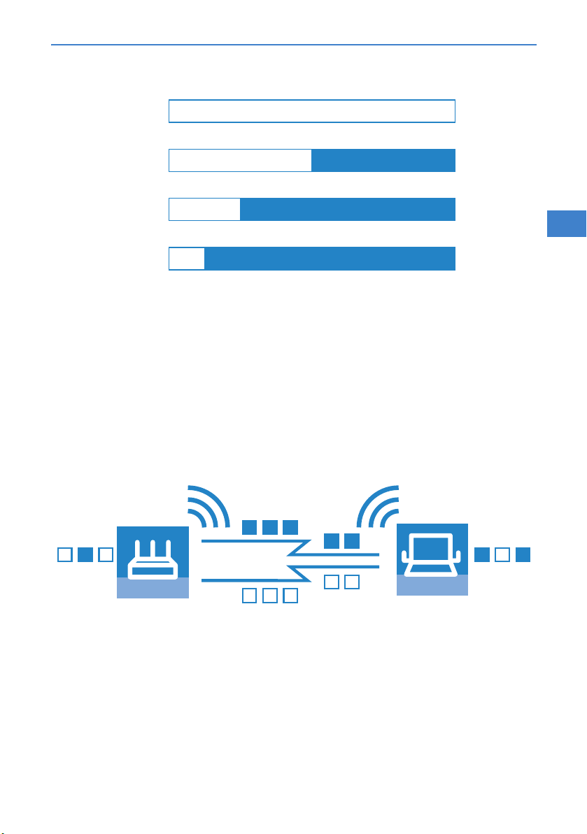
MIMO technology
MIMO (multiple input multiple output) is the most important new technology
contained in 802.11n. MIMO uses several transmitters and several receivers
to transmit up to four parallel data streams on the same transmission channel
(currently only two parallel data streams have been implemented). The result
is an increase in data throughput and improved wireless coverage.
MIMO AP 802.11n
MIMO Client 802.11n
For example, the Access Point splits the data into two groups which are then
sent simultaneously via separate antennas to the WLAN client. Data throughput can therefore be doubled using two transmitting and receiving antennas.
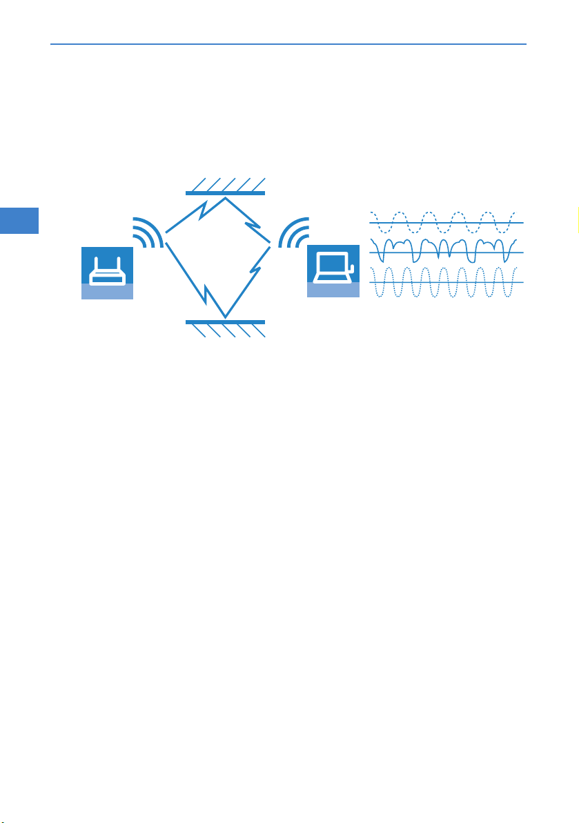
But how can several signals be transmitted on a single channel simultaneously? This was considered impossible with previous WLAN applications.
Let us consider how data is transmitted in "normal" wireless LAN networks:
Depending on antenna type, an Access Point's antenna broadcasts data in
several directions simultaneously. These electromagnetic waves are reflected
EN
13
Page 15
LANCOM OAP-54 Wireless and LANCOM OAP-310agn Wireless
Chapter 1: Introduction
by the surrounding surfaces causing a broadcast signal to reach the WLAN client's antenna over many different paths; this is also referred to as "multipath
propagation". Each of these paths has a different length meaning that individual signals reach the client with a different time delay.
EN
ACCESS POINT
WLAN-Client
These time-delayed signals interfere with each other at the WLAN client and
significantly weaken the original signal. For this reason, conventional WLAN
networks should always have a direct line of sight (LOS) between transmitter
and receiver in order to reduce the influence of reflections.
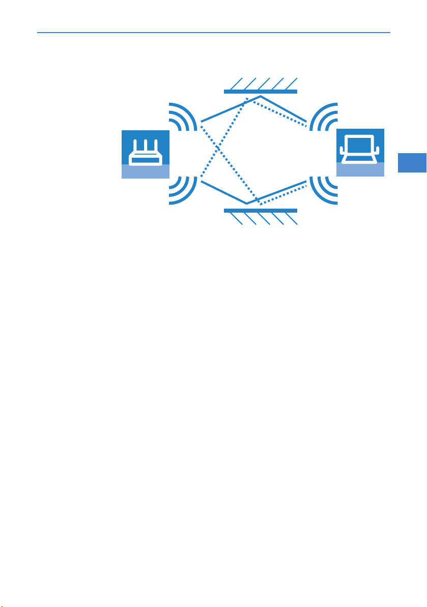
MIMO technology transforms this weakness in WLAN transmission into a
strength that allows an enormous increase in data throughput. As mentioned
above, it is virtually impossible to transmit different signals on the same channel simultaneously as the receiver cannot distinguish between them. MIMO
uses the reflection of electromagnetic waves and the associated spatial aspect
to obtain a third criterion for identifying the signals.
A signal sent by transmitter A and received by receiver 1 follows a different
path than a signal from transmitter B to receiver 2. Due to the different reflections and changes in polarization that both signals experience along their
paths, each of these paths takes on its own characteristics. When data transmission starts, a training phases records the characteristics of the path by
transmitting standardized data. Subsequently, the data received here is used
to calculate which data stream the signals belong to. The receiver decides for
itself which of the incoming signals is to be processed, thus avoiding loss from
interference.
14
Page 16
LANCOM OAP-54 Wireless and LANCOM OAP-310agn Wireless
Chapter 1: Introduction
A
MIMO AP 802.11n
B
MIMO thus allows the simultaneous transmission of several signals over one
shared medium, such as the air. Individual transmitters and receivers must be
positioned a minimum distance apart from one another, although this is just
a few centimeters. This separation results in differing reflections and signal
paths that can be used to separate the signals.
Generally speaking, MIMO can provide up to fo ur parallel data strea ms, whi ch
are also called "spatial streams". However, the current generation of chips can
only implement two parallel data streams as the separation of data streams
based on characteristic path information demands high levels of computing
power, which consumes both time and electricity. The latter tends to be undesirable particularly for WLAN systems, where attempts are often made to
achieve independence from power sockets at the WLAN client or when using
PoE as the electricity supply for the Access Point.
Even if the aim of four spatial streams has not yet been achieved, the use of
two separate data connections results in a doubling of data throughput,
which represents a true technological leap in th e area of WLAN sys tems. Combined with the improvements in OFDM modulation, the data throughput that
can be attained increases to 130 Mbps.
The short description "transmitter x receiver" expresses the actual number of
transmitting and receiving antennas. 3x3 MIMO describes three transmitting
and three receiving antennas. However, the number of antennas does not
equate with the number of data streams: the antennas available only limit the
maximum number of spatial streams. The reason for using more antennas
than strictly necessary for data stream transmission relates to the method of
allocating the signals according to their characteristic path: A third signal is
used to transmit additional spatial information. If the data from the first two
1
MIMO Client 802.11n
2
EN
15
Page 17
LANCOM OAP-54 Wireless and LANCOM OAP-310agn Wireless
Chapter 1: Introduction
signals cannot be uniquely identified, their computation can still be performed
with the aid of the third signal. The use of additional antennas does not contribute to an increase in data throughput, but it does result in a more even,
stronger coverage for clients.
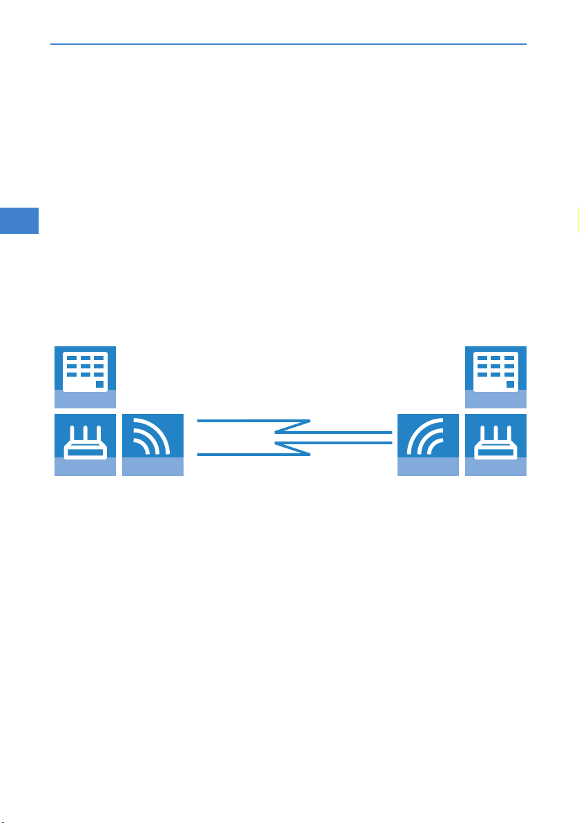
MIMO in outdoor use
Outdoor 802.11n applications cannot use natural reflections since signal
EN
transmission usually takes place over the direct path between directional
antennas. In order to transmit two data streams in parallel, special antennas
are employed that use polarization channels turned through 90° to each
other. These so-called "dual-slant" antennas are really two antennas in one
housing. Since a third signal does not offer additional reliability, outdoor
applications generally use as many antennas (or polarization channels) as
there are data streams for transmission.
BUILDING
MIMO AP 802.11n
16
BUILDING
POLARIZATION
DIVERSITY
POLARISATION
DIVERSITY
MIMO AP 802.11n
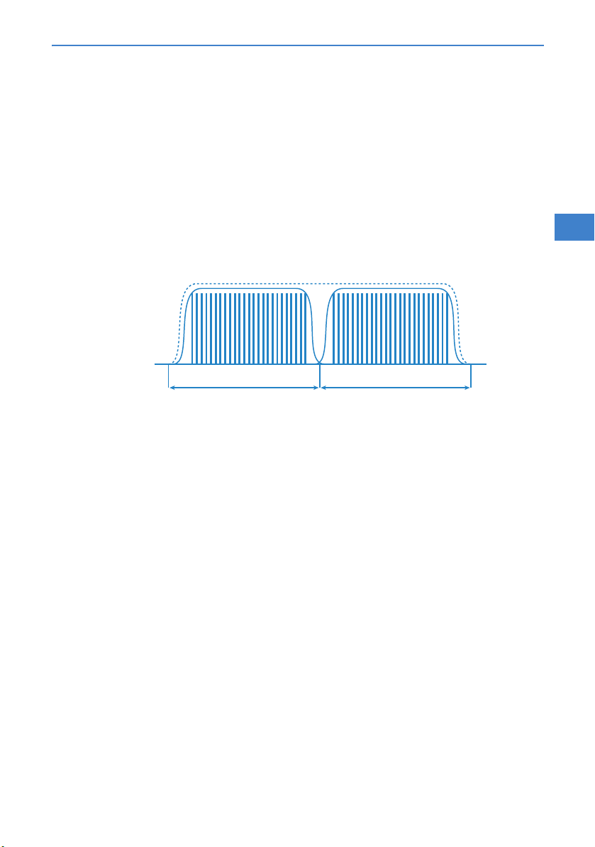
40 MHz channels
As the above explanation of OFDM modulation states, data throughput rises
with an increasing number of carrier signals because this allows several signals to be transmitted simultaneously. If a channel with a bandwidth of
20 MHz supports no more than 48 (802.11a/g) or 52 (802.11n) carrier signals,
the obvious choice would be to use a second channel with additional carrier
signals.
This method was used in the past by a number of manufacturers (including
LANCOM Systems) and was referred to as "turbo mode", allowing data rates
of up to 108 Mbps. Turbo mode does not form part of the official IEEE standard but is frequently employed on point-to-point connections, for example,
because compatibility to other manufacturers tends to play a secondary role.
However, the success of the underlying technology has lead to its incorporation into 802.11n. IEEE 802.11n uses the second transmission channel in a
Page 18
LANCOM OAP-54 Wireless and LANCOM OAP-310agn Wireless
Chapter 1: Introduction
way that maintains compatibility to IEEE 802.11a/g devices. 802.11n transmits data over two contiguous channels. One of these assumes the task of a
control channel that, among other things, handles the administration of data
transmission. Concentrating these basic tasks into the control channel means
that devices supporting a transmission at 20 MHz only can also be connected.
The second channel is an extension that only comes comes into effect if the
remote client also supports data transmission at 40 MHz. The use of the
second channel remains optional throughout, with transmitter and receiver
deciding dynamically whether one or two channels should be employed.
Control channel Extension channel
20 MHz 20 MHz
As the implementation of 40 MHz with separate control and extension channels is more efficient in the 802.11n standard than in the conventional turbo
mode, more than double the amount of carrier signals can be obtained (108
in total). The maximum data throughput when using improved OFDM modulation and two parallel data streams thus rises to 270 Mbps.
EN
Short guard interval
The final improvement of the 802.11n standard is the improvement in the
chronological sequence of data transmission. A signal that is to be transmitted in a WLAN system is not broadcast at a distinct point in time but is "held
up" for a certain, constant transmission period. In order to prevent interference at the receiving end, a short break is made following the transmission
period before the transmission of the next signal commences. The entire duration of transmission period and break are referred to in WLAN terminology as
"symbol length" and the break itself is known as the "guard interval".
IEEE 802.11a/g uses a symbol length of 4 μs: the information transmitted on
the carrier signal changes following transmission of 3.2 μs and a break of
0.8 μs. 802.11n reduces the break between transmissions to the so-called
"short guard interval" of only 0.4 μs.
17
Page 19

LANCOM OAP-54 Wireless and LANCOM OAP-310agn Wireless
Chapter 1: Introduction
OFDM Symbol
3,2 μs 0,8 μs
Payload data
EN
3,2 μs
Transmitting data in shorter intervals thus increases the maximum data
throughput when using improved OFDM modulation, two parallel data
streams and transmission at 40 MHz to 300 Mbps.
1.2.4 The MAC layer
Frame aggregation
The improvements in the physical layer brought about by the new 802.11n initially describe only the theoretical data throughput of the physical medium.
However, the share of this theoretical bandwidth that is actually available for
payload data is limited by two factors:
in addition to the actual payload data, each data packet in a wireless LAN
system contains additional information such as a preamble and MAC
address information.
Time is lost to the management events that occur when the transmission
medium is actually accessed. Thus the transmitter must negotiate access
authorization with the other receivers before transmitting each data
packet (frame); further delays are caused by data packet collisions and
other events.
This loss, referred to as "overhead", can be reduced by combining several data
packets together to form one large frame and transmitting them together. In
this process, information such as the preamble are only transmitted once for
all the combined data packets and delays due to negotiating access to the
transmission medium only occur at longer intervals.
The use of this method, known as frame aggregation, is subject to certain
restrictions:
As information such as MAC address only needs to be transmitted once
for the aggregated frame, only those data packets intended for the same
address can be combined.
0,4 μs
18
Page 20

LANCOM OAP-54 Wireless and LANCOM OAP-310agn Wireless
Chapter 1: Introduction
All data packets that are to be combined into a single large frame must
be available at the sender at the time of aggregation—as a consequence
some data packets may have to wait until enough data packets for the
same destination are available with which they can be combined. This
aspect may represent a significant limitation for time-critical transmissions such as voice over IP.
Block acknowledgement
Each data packet directed to a specific address (i.e. not broadcast or multicast
packets) is acknowledged immediately after receipt. In this way, the transmitter is informed that the packet was received correctly and does not need to be
repeated. This principle also applies to aggregated frames in 802.11n.
Two different methods are used for frame aggregation. These are not explained in detail here, but they differ in the way aggregated frames are acknowledged.
Mac Service Data Units Aggregation (MSDUA) combines several Ethernet
packets together to form one common wireless LAN packet. This packet is
acknowledged only once and the acknowledgment is valid for all aggregated packets. If there is no acknowledgement the whole block is resent.
Mac Protocol Data Units Aggregation (MPDUA) combines individual wire-
less LAN packets together to form one large common wireless LAN packet.
In this case, each wireless LAN packet is acknowledged and the acknowledgements are combined and transmitted as a block. In contrast to
MSDUA, the sender receives information about the receipt status of every
single WLAN packet and can, if necessary, resend only those specific
packets that were not successful.
EN
19
Page 21

LANCOM OAP-54 Wireless and LANCOM OAP-310agn Wireless
Chapter 1: Introduction
1.3 Just what can your LANCOM Wireless Router do?
The following table provides a comparison of the properties and functions of
your device.
EN
Applications
Outdoor operation in tough environments with extreme
temperature ranges (high temperature stability)
Internet Access
IP router with Stateful Inspection Firewall
DHCP and DNS server (for LAN and WAN)
N:N mapping for routing networks with the same IPaddress ranges over VPN
Policy-based routing
Backup solutions and load balancing with VRRP
PPPoE Server
WAN RIP
Spanning Tree protocol
Layer 2 QoS tagging
VPN gateway (optional)
WLAN
Wireless transmission by IEEE 802.11g and IEEE 802.11b
Wireless transmission by IEEE 802.11a and IEEE 802.11h
Wireless transmission by IEEE 802.11n (including 40
MHz channels, packet aggregation, block acknowledgement, short guard interval)
Point-to-point mode (six P2P paths can be defined per
WLAN interface)
Relay function to link two P2P connections
Access point mode
Client mode
LANCOM
OAP-54
Wireless
LANCOM
OAP-310agn
Wireless
✔✔
✔✔
✔✔
✔✔
✔✔
✔✔
✔✔
✔✔
✔✔
✔✔
✔✔
✔
✔✔
✔✔
✔
✔✔
✔
✔✔
✔✔
20
Page 22

LANCOM OAP-54 Wireless and LANCOM OAP-310agn Wireless
Chapter 1: Introduction
Managed mode for central configuration of WLAN modules by a WLAN Controller
Turbo Modus: Bandbreitenverdopplung im 2,4 GHz- und
5 GHz-Bereich
Super AG inkl. Hardware-Compression und Bursting
Multi SSID
Roaming function
802.11i / WPA with hardware AES encryption
WEP encryption (up to 128 Bit key length, WEP152)
IEEE 802.1x/EAP
MAC address filter (ACL)
Individual passphrases per MAC address (LEPS)
Closed network function
Integrated RADIUS server
VLAN
Intra-Cell Blocking
WLAN QoS (IEEE 802.11e, WME)
LAN connection
Fast Ethernet LAN port (10/100Base-TX)
Power-over-Ethernet (PoE)
DHCP and DNS server
WAN connection
Connection for DSL or cable modem
Internet connection (IP-Router)
Stateful Inspection Firewall
Firewall filters (IP addresses, ports)
IP-Masquerading (NAT, PAT)
LANCOM
OAP-54
Wireless
LANCOM
OAP-310agn
Wireless
✔✔
✔
✔
✔✔
✔✔
✔✔
✔✔
✔✔
✔✔
✔✔
✔✔
✔✔
✔✔
✔✔
✔✔
✔✔
✔✔
✔✔
✔✔
✔✔
✔✔
✔✔
EN
21
Page 23

LANCOM OAP-54 Wireless and LANCOM OAP-310agn Wireless
Chapter 1: Introduction
EN
Quality of Service (QoS)
VPN gateway with VPN hardware encryption (optional)
Power supply
Power-over-Ethernet (PoE)
Configuration and firmware
Configuration with LANconfig or with web browser,
additionally terminal mode for Telnet or other terminal
programs, SNMP interface and TFTP server function.,
SSH connection.
Setup wizards
FirmSafe with firmware versions for absolutely secure
software upgrades
Monitoring and management of the WLAN with Rogue
AP Detection
Optional software extensions
LANCOM Public Spot Option
LANCOM VPN Option with 25 active tunnels for protection of network couplings
Optional hardware extensions
AirLancer Extender antennas for increased range
LANCOM PoE Power Injector (100 Mbps)
Housing
IP66-rated housing for deployment in extreme environments
LANCOM
OAP-54
Wireless
LANCOM
OAP-310agn
Wireless
✔✔
✔
✔✔
✔✔
✔✔
✔✔
✔✔
✔
✔✔
✔✔
✔✔
22
Page 24

LANCOM OAP-54 Wireless and LANCOM OAP-310agn Wireless
Chapter 2: Installation
2 Installation
This chapter will assist you to quickly install hardware and software. First,
check the package contents and system requirements. The device can be
installed and configured quickly and easily if all prerequisites are fulfilled.
2.1 Package contents
Please check the package contents for completeness before starting the
installation. In addition to the base station itself, the package should contain
the following accessories:
LANCOM
OAP-54
Wireless
LAN cable for connecting to PoE Injector with waterproof
screw connections, 15 m
External 360° dualband antennas with reverse N-plug 2 3
Adapter cable reverse N-jack to N- plug, 1,5 m 3 2
Adapter cables reverse N-jack to N- plug, 10 cm 2 2
Mast and wall mount accessories
High Power PoE Injekor (802.3af compatible)
Power cable for PoE Power Injector
Grounding cable with srews
Terminator for a free antanna connector 1 2
LANCOM CD
Printed documentation
✔✔
✔✔
✔✔
✔✔
✔✔
✔✔
✔✔
LANCOM
OAP-310agn
Wireless
If anything is missing, please contact your retailer or the address stated on the
delivery slip of the unit.
EN
2.2 System requirements
2.2.1 Configuring the LANCOM devices
Computers that connect to a LANCOM must meet the following minimum
requirements:
23
Page 25

LANCOM OAP-54 Wireless and LANCOM OAP-310agn Wireless
Chapter 2: Installation
Operating system with TCP/IP support, suchas Windows, Linux, BSD Unix,
Apple Mac OS, OS/2.
Access to the LAN via the TCP/IP protocol.
Wireless LAN adapter or LAN access (if the access point is to be connected
to the LAN).
The LANtools also require a Windows operating system. A web brow-
EN
ser under any operating system provides access to WEBconfig.
2.2.2 Operating access points in managed mode
LANCOM Wireless Routers and LANCOM Access Points can be operated either
as self-sufficient Access Points with their own configuration ("Access Point
mode“) or as components in a WLAN infrastructure, which is controlled from
a central WLAN-Controller ("managed mode").
2.3 Status displays and interfaces
Meanings of the LEDs
In the following sections we will use different terms to describe the behaviour
of the LEDs:
Blinking means, that the LED is switched on or off at regular intervals in
the respective indicated colour.
Flashing means, that the LED lights up very briefly in the respective
colour and stay then clearly longer (approximately 10x longer) switched
off.
Inverse flashing means the opposite. The LED lights permanently in the
respective colour and is only briefly interrupted.
Flickering means, that the LED is switched on and off in irregular inter-
vals.
24
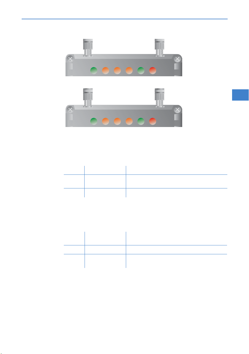
2.3.1 LEDs of LANCOM OAP-54 Wireless and LANCOM OAP-310agn Wireless
The front and the rear panels of the unit feature a series of light emitting
diodes (LEDs) that provide information on the status of the device.
Page 26
LANCOM OAP-54
Wireless
LANCOM OAP-54 Wireless and LANCOM OAP-310agn Wireless
Chapter 2: Installation
LANCOM OAP-310agn
Wireless
Power
LAN
WLAN1
(LANCOM
OAP-54
Wireless only)
Power LAN
WLAN-1WLAN
-2
WAN Message
WLAN
Power LAN
Link
WLAN
Data
WAN Message
This LED indicates that the device is operational. After the device has been
switched on, the LED remains lit green.
Status of the LAN port
off No network device connected
yellow constantly on Connection to network device operational; transfer rate
yellow inverse flashing Data traffic
10 or 100 Mbps
Gives information about the wireless LAN access of the first internal wireless
network adapter of the base station. The WLAN link display can assume three
states:
EN
WLAN2
(LANCOM
OAP-54
Wireless only)
WLAN Link
(LANCOM
OAP-310agn
Wireless only)
off WLAN module out of order or deactivated in the device
yellow constantly on Wireless LAN adapter ready for use
yellow inverse flashing Number of flashes: number of WLAN stations connected
configuration
and p2p links, followed by a pause
Gives information about the wireless LAN access of the second internal wireless network adapter of the base station. Meaning as desribed for WLAN1.
Provides information about the WLAN connections via the internal WLAN
module.
25
Page 27

LANCOM OAP-54 Wireless and LANCOM OAP-310agn Wireless
Chapter 2: Installation
The following can be displayed for WLAN link:
EN
WLAN Data
(LANCOM
OAP-310agn
Wireless only)
WAN
Off No WLAN network defined or WLAN module deactiva-
Yellow At least one WLAN network is defined and WLAN
Yellow Inverse flashing Number of flashes = number of connected WLAN stati-
Yellow Blinking DFS scanning or other scan procedure.
ted. The WLAN module is not transmitting beacons.
module activated. The WLAN module is transmitting
beacons.
ons and P2P wireless connections, followed by a pause
(default).
Alternatively, the frequency of the flashed can indicate
the received signal strength of a P2P link or the received
signal strength from an access point, to which this
device is connected in client mode.
Provides information about the data traffic at the internal WLAN module.
The following can be displayed for WLAN data:
Yellow Flickering TX data traffic.
Connection status of the WAN interface. The WAN link display can assume
three states:
off Not connected
green constantly on Connection established
green inverse flashing Data transfer via WAN
26
Page 28

LANCOM OAP-54 Wireless and LANCOM OAP-310agn Wireless
Chapter 2: Installation
Message
Flashing Message-LED but no connection?
There's no need to worry if the Message- LED blinks red and you
con no longer connect to the WAN. This simply indicates that a
preset time or connect-charge limit has been reached.
There are three methods available for unlocking:
Reset connect charge protection.
Increase the limit that has been reached.
Completely deactivate the lock that has been triggered (set
limit to '0').
If a time or connect charge limit has been reached, you will be notified in LANmonitor. To
reset the connect charge protection, select Reset Charge and Time Limits in the context
menu (right mouse click). You can configure the connect charge settings in LANconfig under
Management Costs (you will only be able to access this configuration if 'Complete configuration display' is selected under View Options…).
You will find the connect charge protection reset in WEBconfig and all parameters under:
LCOS Menu Tree Setup Charges-module
Gives general information about the device.
Signal for reached time or
charge limit
off Device ready for use
red flashing (slow) Time or connect-charge reached
red flashing (fast) Device insecure: configuration password not assigned
red flickering WLAN module defected
EN
The power LED flashes red when a charge limit is reached.
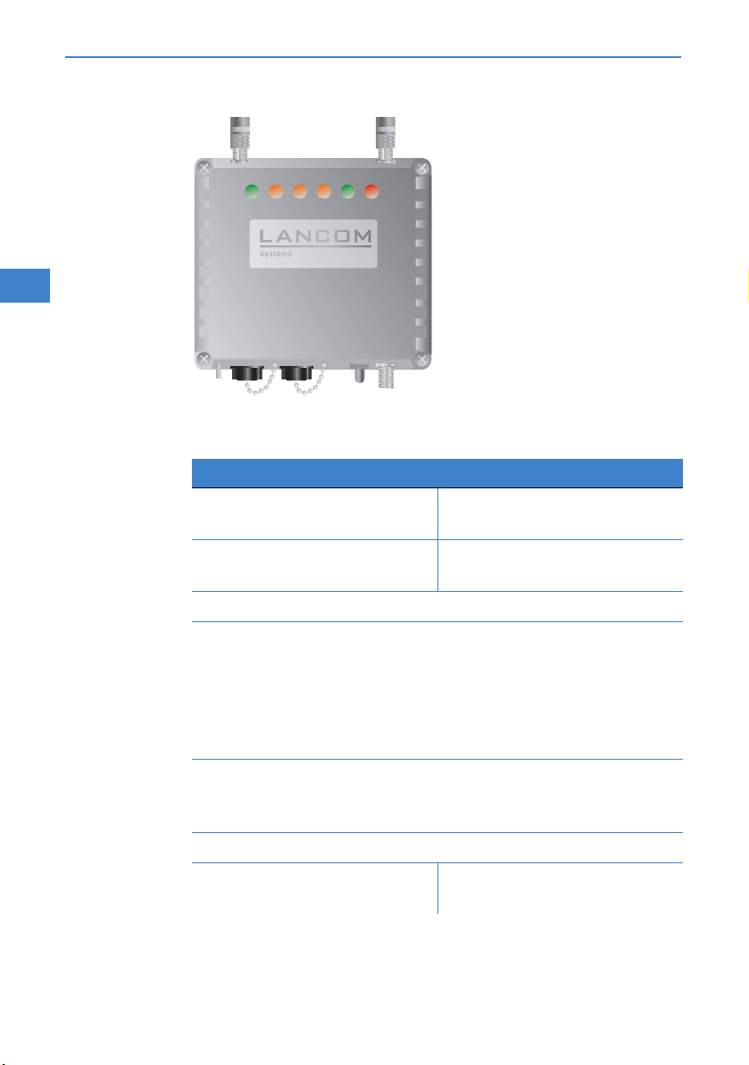
2.4 The device connectors
The connections and switches of the LANCOM OAP-54 Wireless and LANCOM
OAP-310agn Wireless are located on the top and bottom side.
On the top are the two antenna connectors. The bottom side accommodates
the LAN and WAN connectors, the reset button and an additional antenna
connector.
27
Page 29
LANCOM OAP-54 Wireless and LANCOM OAP-310agn Wireless
Chapter 2: Installation
LANCOM OAP-54
Wireless
EN
WLAN-1WLAN
Power LAN
LANCOM OAP-54 Wireless LANCOM OAP-310agn Wireless
Main connector for the first
-2
WAN Message
Connector for antenna 1.
WLAN module.
Aux connector for the first
Connector for antenna 2.
WLAN module.
Earth cable connector.
10/100Base-Tx for connection to the LAN. Both 10 Mbit or 100 Mbit
connections are supported. The available transfer rate is detected automatically (autosensing). The LAN connection features an automatic
MDI/MDIX detector enabling the use of cross-over cables.
The LAN connector on the LANCOM OAP Wireless supports the Power
over Ethernet standard (PoE).
WAN connector; can alternatively be configured as a LAN connector
(also with autosensing of 10/100 Mbps and automatic recognition of
MDI/MDIX).
28
Reset button (see "Reset button functions").
Antenna connector for the sec-
Connector for antenna 3.
ond WLAN module.
Page 30

LANCOM OAP-54 Wireless and LANCOM OAP-310agn Wireless
Chapter 2: Installation
Power over Ethernet – the elegant power supply via LAN cabling
Electricity supply to the LANCOM OAP Wireless takes place via Power over Ethernet. This
requires the use of the Power Injector as included in the scope of supply.
The use of other PoE injector devices, e.g. those compliant with the IEEE 802.3af stand-
ard, is not permitted and using them can cause damage to the devices. The LANCOM
OAP Wireless has a power consumption of up to 25 Watts when operating at its full
heating or cooling capacity. The resulting flow of current in the PoE cable places constraints on the length of cable that can be used.
Due to the high power consumption of the LANCOM OAP Wireless, a disturbance-free power
supply can only be assured with PoE cabling of up to 50m in length.
For the same reason, the maximum length of cable to the next Ethernet switch may not exceed
50m, even if the PoE feed takes place over a shorter length of cable (e.g. when using the 15m
cable).
EN
LAPTOP/W-LAN
ACCESS POINT
Maximum 50 meters between access point and Power Injector/Switch!
To this end, the 15m PoE cable with a waterproof thread as supplied with the LANCOM OAP
Wireless can simply be extended with a coupler. An Ethernet cable coupler and Cat 5 Ethernet
cable are available from specialist resellers.
Please ensure that all cables used are of at least Cat 5 quality. All four conductor pairs
must have contact through all of the cables.
The 1Port Power Injector supplied with the LANCOM OAP Wireless does not comply
fully with the IEEE 802.3af standard. It is suitable for supplying power to the LAN port
of the LANCOM OAP-54 Wireless only. If you wish to safely supply power to other
devices with IEEE802.3af, LANCOM can supply a proprietary LANCOM PoE Injector.
SA-5L
230 V
PoE Switch 48 V
29
Page 31

LANCOM OAP-54 Wireless and LANCOM OAP-310agn Wireless
Chapter 2: Installation
Reset button functions
The reset button is freely accessible on LANCOM OAP-54 Wireless or LANCOM
OAP-310agn Wireless, hence you cannot reset the device by simply pressing
this button. Detach the LAN cable from the corresponding interface to disable
the power supply via PoE. Keep the reset button pressed when re-attaching
the LAN cable. The message LED will start blinking. After the LEDs has finished
blinking, you can release the button and the device has been reset.
EN
After resetting, the device starts completely unconfigured and all set-
tings are lost. If possible be sure to backup the current device configuration before resetting.
After resetting, the LANCOM Access Point returns to managed mode,
in which case the configuration cannot be directly accessed via the
WLAN interface!
2.5 Mounting and connectiong the LANCOM OAP-54 Wireless and LANCOM OAP-310agn Wireless
Before mounting external antennas, please observe the information on lightning pro-
tection in the LANCOM WLAN Outdoor Manual (available as a download from
www.lancom.eu
lead to serious damage to the access point and the network infrastructure connected
to it.
). Mounting antennas without adequate lightning protection could
30
Wall mounting
Your LANCOM OAP Wireless should be mounted with suitable screws
in the required position on the wall. Screws for wall mounting are not supplied with the device.
Page 32

Wall mounting
Pole mounting
LANCOM OAP-54 Wireless and LANCOM OAP-310agn Wireless
Chapter 2: Installation
WLAN-1WLAN
Power LAN
-2
WAN Message
Pole mounting
Place the two U-bolts around the pole and use the supplied nuts and
washers to fix the mounting plate . The package includes two
mounting clamps for poles of different diameters.
EN
Mounting is completed by attaching your LANCOM OAP Wireless with the
help of two screws to the mounting plate.
31
Page 33

LANCOM OAP-54 Wireless and LANCOM OAP-310agn Wireless
Chapter 2: Installation
Connecting the LANCOM OAP Wireless
Installation of the LANCOM OAP-54 Wireless devices involves the following
steps:
Earth connection (if necessary)—attach the earth cable to the earth screw
of the LANCOM OAP Wireless and to a suitable earthed conductor.
When mounting the LANCOM OAP Wireless on poles or walls it may
EN
be necessary to earth the housing to avoid dangerous differences in
potential. For grounding the LANCOM OAP Wireless please observe
the information on lightning protection in the LANCOM WLAN Outdoor Manual (available as a download from www.lancom.eu
Antennas—screw the two supplied diversity antennas onto the two N
connectors on the top of the LANCOM OAP Wireless. An additional
antenna for the second WLAN module can be connected to the reverse N
connector on the underside of the device.
Antennas are only to be attached or changed when the device is
switched off. Mounting or demounting antennas while the device
switched on may cause the destruction of the WLAN module!
)
32
Antennas for LANCOM OAP-54 Wireless—screw the two supplied diver-
sity antennas onto the two N connectors on the top of the LANCOM OAP
Wireless. An additional antenna for the second WLAN module can be connected to the reverse N connector on the underside of the device.
Antennas for LANCOM OAP-310agn Wireless—screw the supplied anten-
nas onto the N connectors on the top and bottom of the LANCOM OAP
Wireless. Depending on how the antennas are to be used, the 'Antenna
Grouping' parameter may need to be configured in order provide the
desired MIMO behavior (→ 'Advanced Wireless LAN Configuration').
To attach an external antenna to a reverse N connector, use one of the
supplied "reverse N" to "N" adapter cables.
When assembling separately purchased mobile radio antennas please
note that the maximum allowed transmission power of the wireless
LAN according to EIRP in the country in question may not be
exceeded. The system operator is responsible for adhering to the
threshold values.
Page 34

LANCOM OAP-54 Wireless and LANCOM OAP-310agn Wireless
Chapter 2: Installation
The employment of the AirLancer Extender SA-5L for internal light-
ning protection is essential under all circumstances—the
AirLancer Extender SA-5L is always mounted between the Access
Point and the antenna, preferably as near as possible to the antenna.
Antennas are only to be attached or changed when the device is
switched off. Mounting or demounting antennas while the device
switched on may cause the destruction of the WLAN module!
LAN—The LAN connector is also used to supply power to the LANCOM
OAP Wireless. Plug in the water-proof power cable to the LAN port on the
underside of the device and carefully tighten the threaded connector.
Connect the other end of the power cable to the 'Power Out' connector
on the supplied PoE Injector.
PoE—the 'LAN In' connector of the supplied PoE Injector should be con-
nected via a normal Ethernet cable to an available network connection
socket in your local network (e.g. an available socket on a hub or switch)
and the PoE Injector connected with the electricity supply.
Information about the installation of PoE can be found in the information
box 'Power over Ethernet—elegant power supply over LAN cabling'
above.
Please observe the information in the documentation supplied with the
PoE Injector.
EN
Use the PoE Injector only for the supply of power to PoE-compatible
devices. Pay particular care not to connect the PoE Injector to normal
Ethernet devices!
WAN—if you wish to make use of the integrated DSL router for a direct
WAN connection, plug in the supplied WAN cable to the WAN connector
on the underside of the device and carefully tighten the threaded connector. Connect the other end of the WAN cable to an ADSL or cable
modem.
Waterproof WAN cables from LANCOM Systems are available on order
from specialist resellers.
Ready for operation? —the Power LED permanently lights up in green as
soon as the device receives power. After being switched on, the device
33
Page 35

LANCOM OAP-54 Wireless and LANCOM OAP-310agn Wireless
Chapter 2: Installation
carries out a self-test as shown by the blinking Message LED. The LEDs
subsequently display the operational status.
2.6 Software installation
The following section describes the installation of the Windows-compatible
system software LANtools, as supplied.
EN
You may skip this section if you use your LANCOM OAP Wireless exclu-
sively with computers running operating systems other than Windows.
2.6.1 Starting the software setup
Place the product CD into your drive. The setup program will start automatically.
If the setup does not start automatically, run AUTORUN.EXE in the
root directory of the LANCOM CD.
In Setup, select Install software. The following selection menus will appear
on screen:
34
Page 36

LANCOM OAP-54 Wireless and LANCOM OAP-310agn Wireless
2.6.2 Which software should I install?
LANconfig is the Windows configuration program for all LANCOM rou-
ters and LANCOM access points. WEBconfig can be used alternatively
or in addition via a web browser.
With LANmonitor you can use a Windows computer to monitor all of
your LANCOM routers and LANCOM access points.
WLANmonitor enables the observation and surveillance of wireless
LAN networks. Clients connected to the access points are shown, and
even non-authenticated access points and clients can be displayed as
well (rogue AP detection and rogue client detection).
With Documentation you copy the documentation files onto your PC.
Select the appropriate software options and confirm your choice with Next.
The software is installed automatically.
Chapter 2: Installation
EN
35
Page 37

LANCOM OAP-54 Wireless and LANCOM OAP-310agn Wireless
Chapter 3: Basic configuration
3 Basic configuration
The basic configuration is conducted with a convenient Setup Wizard that
provides step-by-step guidance through the configuration and that requests
any necessary information.
Unconfigured LANCOM Access Points with standard factory settings
cannot be commissioned by means of the WLAN interface.
EN
First of all this chapter presents the information that has to be entered for the
basic configuration. This first section will help you to gather up all of the
necessary data before you start the Wizard.
You subsequently enter this information into the Setup Wizard. Starting the
program and the following procedure are described step by step. LANconfig
and WEBconfig each have their own description. With all of the necessary
information collected in advance, this basic configuration can now take place
quickly and in ease.
At the end of this chapter we show you the necessary settings for the workplace computers in the LAN so that they can access the device without problem.
For LANCOM Access Points that are unconfigured and in their factory settings,
the WLAN modules are switched off and set to the "Managed" operating
mode. The WLAN modules search the LAN for a LANCOM WLAN Controller
from which they can receive their WLAN-interface configuration profiles.
Once executed, the Basic Settings Wizard automatically resets the WLANmodule operating mode to "Access Point". The WLAN interface then has to be
configured manually.
36
Only activate the Basic Settings Wizard if the Access Point is not to be
configured from a WLAN-Controller. Subsequently execute the WLAN
Wizard → WLAN Configuration.
3.1 Details you will need
The Basic Settings Wizard is used to set the LANCOM OAP Wirelesss basic TCP/
IP parameters and to protect the device with a configuration password. The
following description of the information required by the wizard is divided into
the following configuration sections:
TCP/IP settings
Protecting the configuration
Page 38

Wireless LAN details
Security settings
3.1.1 TCP/IP settings
TCP/IP configuration can be performed in two different ways: Either fully automatically or manually. No user input is required if TCP/IP configuration is performed automatically. All parameters are set by the Setup Wizard on its own.
When manual TCP/IP configuration is performed the wizard prompts for the
usual TCP/IP parameters: IP address, network mask etc. (more on this later)
The fully automatic TCP/IP configuration is only possible in certain network
environments. For this reason the Setup Wwizard analyses the connected LAN
to see whether fully automatic configuration is possible or not.
New LAN – fully automatic configuration possible
The setup wizard offers to configure TCP/IP fully automatically if no network
devices connected have yet been configured. This usually happens in the following situations:
Only a single PC is going to be attached to the LANCOM OAP Wireless
Setting up a new network
Fully automatic TCP/IP configuration will not be offered if you are integrating
the LANCOM OAP Wireless into an existing TCP/IP LAN. In this case please
continue with the section 'Required information for manual TCP/IP configuration'.
The result of fully automatic TCP/IP configuration is as follows: The LANCOM
OAP Wireless is assigned the IP address '172.23.56.254' (network mask
'255.255.255.0'). The integrated DHCP server is also activated so that the
LANCOM OAP Wireless can assign the devices in the LAN IP addresses automatically.
LANCOM OAP-54 Wireless and LANCOM OAP-310agn Wireless
Chapter 3: Basic configuration
EN
Should you still configure manually?
Fully automatic TCP/IP configuration is optional. Instead of this you can select
manual configuration. Make this selection after considering the following:
Select automatic configuration if you are not familiar with networks and
IP addresses.
Select the manual TCP/IP configuration if you are familiar with networking
and IP addresses, and you would like to specify the IP address for the router yourself (from one of the address ranges reserved for private use,
37
Page 39

LANCOM OAP-54 Wireless and LANCOM OAP-310agn Wireless
Chapter 3: Basic configuration
for example '10.0.0.1' with a network mask of '255.255.255.0'). If you
do this you simultaneously specify the address range that the DHCP server
will subsequently use for the other devices in the network (provided the
DHCP server is activated).
Required information for manual TCP/IP configuration
When performing manual TCP/IP configuration the Setup Wwizard prompts
EN
you for the following information:
DHCP mode of operation
Off: The IP addresses required must be entered manually.
Server: The LANCOM OAP Wireless operates as DHCP server in the
network; as a minimum its own IP address and the network mask
must be assigned.
Client: The LANCOM OAP Wireless obtains its address information
from another DHCP server; no address information is required.
IP address and network mask for the LANCOM OAP Wireless
Assign the LANCOM OAP Wireless a free IP address from your LAN's
address range and enter the network mask.
Gateway address
Enter the gateway's IP address if you have selected 'Off' as the DHCP
mode of operation or if another network device is assuming the role of
gateway in the 'Server' mode of operation.
DNS server
Enter the IP address of a DNS server to resolve domain names if you have
selected 'Off' as the DHCP mode of operation or if another network device
is assuming the role of DNS server in the 'Server' mode of operation.
38
3.1.2 Configuration protection
Using a password secures access to the LANCOM OAP Wireless's configuration and thus prevents unauthorized modification. The device's configuration
contains a great deal of sensitive data such as data for Internet access and
should be protected by a password in all cases.
Multiple administrators can be set up in the configuration of the
LANCOM, each with different access rights. Up to 16 different administrators can be set up for a LANCOM OAP Wireless. Further information can be found in the LCOS reference manual under “Managing
rights for different administrators”.
Page 40

LANCOM OAP-54 Wireless and LANCOM OAP-310agn Wireless
In the managed mode the LANCOM Wireless Routers and LANCOM
Access Points automatically receive the same root password as the
WLAN-Controller, assuming that no root password has been set in the
device itself.
3.1.3 Settings for the wireless LAN
There is a handy installation wizard to help you with the LANCOM Access
Point's wireless LAN configuration. After performing the basic configuration
please execute the wizard to configure the wireless LAN interface (→ 'WLAN
configuration with the wizards in LANconfig').
Network name (SSID)
The Basic Settings Wizard prompts for the access point's network name (frequently referred to as SSID – Service Set Identifier). The name is of your own
choice. Several access points with the same name form a common wireless
LAN.
Open or closed wireless LAN?
Mobile wireless devices select the desired wireless LAN by specifying the network name. Two methods serve to facilitate the specification of network
name:
Mobile wireless devices can search ("scan") the vicinity for wireless LANs
and offer the wireless LANs they find in a list for selection.
By using the network name 'ANY' the mobile wireless device registers with
the nearest available wireless LAN.
The wireless LAN can be "closed" in order to prevent this procedure. In this
case it will not accept any devices attempting to register with the network
name 'ANY'.
Chapter 3: Basic configuration
EN
Selecting a radio channel
The access point operates in a specific radio channel. The radio channel is
selected from a list of up to 13 channels in the 2.4 frequency band or up to 19
channels in the 5 GHz frequency band (individual radio channels are blocked
in some countries. Please refer to the appendix for more details).
The channel and frequency range used determine the operation if the common wireless standard, with the 5 GHz frequency range corresponding to the
IEEE 802.11a/h standard and the 2.4 GHz frequency range determining operation in the IEEE 802.11g and IEEE 802.11b standards.
39
Page 41

LANCOM OAP-54 Wireless and LANCOM OAP-310agn Wireless
Chapter 3: Basic configuration
If no other access points are operating within the access point's range, any
radio channel can be set. Otherwise the channels in the 2.4 GHz band must
be selected in such a way that they do not overlap and are as far apart as possible. In the 5 GHz band the automatic setting, where the LANCOM Access
Point uses TPC and DFS to select the best channel is normally sufficient.
Please refer to the LCOS reference manual for more information on
TPC and DFS.
EN
3.2 Instructions for LANconfig
Start LANconfig with Start Programs LANCOM LANconfig.
LANconfig automatically detects new LANCOM devices in the TCP/IP network.
If the search detects an unconfigured device, the Setup Wizard launches
to help you with its basic settings, or indeed to handle the entire process
on your behalf (assuming that the appropriate networking environment
exists).
40
If the Setup Wizard does not start automatically, you can manually
search for new devices at all interfaces (if the LANCOM OAP Wireless
is connected via the serial configuration interface) or in the network
(File Find devices).
If the Setup Wizard does not start automatically, you can search for
new devices in the network manually (File Find devices).
If you cannot access an unconfigured LANCOM OAP Wireless, the pro-
blem may be the LAN netmask: In case there are less than 254 potential hosts available (netmask >'255.255.255.0'), you must ensure that
the IP address 'x.x.x.254' is available in your subnet.
Page 42

LANCOM OAP-54 Wireless and LANCOM OAP-310agn Wireless
Chapter 3: Basic configuration
If you choose automatic TCP/IP configuration, you can continue with step
.
Give the LANCOM an address from the applicable IP address range. Con-
firm with Next.
In the window that follows, you first set the password to the configura-
tion. Entries are case sensitive and should be at least 6 characters long.
You also define whether the device can be configured from the local network only, or if remote configuration via WAN (i.e.. from a remote network) is to be permitted.
Be aware that releasing this option also allows remote configuration
over the Internet. Whichever option you select, make sure that configuration access is password protected.
Enter the wireless parameters. Set a network name (SSID) and a radio
channel. If preferred, activate the "closed network" function. Accept your
entries with Next.
Charge protection is a function which can place a limit on the costs from
WAN connections. Accept your entries with Next.
Close the configuration with Finish.
See the section 'TCP/IP settings for PC workstations' for information
on the settings that are required for computers in the LAN.
3.3 Instructions for WEBconfig
Device settings can be configured from any Web browser. WEBconfig configuration software is an integral component of the LANCOM. A Web browser is
all that is required to access WEBconfig. WEBconfig offers similar Setup
Wizards to LANconfig and hence provides the perfect conditions for easy configuration of the LANCOM – although, unlike LANconfig, it runs under any
operating system with a Web browser.
EN
Secure with HTTPS
WEBconfig offers secure (remote) configuration by encrypting the configuration data with HTTPS.
https://<IP address or device name>
41
Page 43

LANCOM OAP-54 Wireless and LANCOM OAP-310agn Wireless
Chapter 3: Basic configuration
Always use the latest version of your browser to ensure maximum
security.
Accessing the device with WEBconfig
To carry out a configuration with WEBconfig, you need to know how to contact the device. Device behavior and accessibility for configuration via a Web
browser depend on whether the DHCP server and DNS server are active in the
EN
LAN already, and whether these two server processes share the assignment in
the LAN of IP addresses to symbolic names. WEBconfig accesses the LANCOM
either via its IP address, the device name (if configured), or by means of any
name if the device has not yet been configured.
Following power-on, unconfigured LANCOM devices first check whether a
DHCP server is already active in the LAN. Depending on the situation, the
device can either enable its own DHCP server or enable DHCP client mode. In
the second operating mode, the device can retrieve an IP address for itself
from a DHCP server in the LAN.
If a LANCOM Wireless Router or LANCOM Access Point is centrally
managed from a LANCOM WLAN Controller, the DHCP mode is switched from auto-mode to client mode upon provision of the WLAN
configuration.
Not for centrally
managed LANCOM
Wireless Routers or
LANCOM Access
Points
42
Network without a DHCP server
In a network without a DHCP server, unconfigured LANCOM devices enable
their own DHCP server service when switched on and assign IP addresses,
information on gateways, etc. to other computers in the LAN (provided they
are set to automatic retrieval of IP addresses – auto DHCP). In this constellation, the device can be accessed by every computer with the auto DHCP function enabled with a Web browser under IP address 172.23.56.254.
With the factory settings and an activated DHCP server, the device for-
wards all incoming DNS requests to the internal Web server. This
means that a connection can easily be made to set set up an unconfigured LANCOM by entering any name into a Web browser.
Page 44

LANCOM OAP-54 Wireless and LANCOM OAP-310agn Wireless
Chapter 3: Basic configuration
If the configuration computer does not retrieve its IP address from the
LANCOM DHCP server, it determines the current IP address of the computer
(with Start Run cmd and command ipconfig at the prompt under Win-
dows 2000 or Windows XP or Windows Vista, with Start Run cmd and
command winipcfg at the prompt under Windows Me or Windows 9x, or
with command ifconfig in the console under Linux). In this case, the LANCOM
can be accessed with address x.x.x.254 (the “x”s stand for the first three
blocks in the IP address of the configuration computer).
EN
Network with DHCP server
If a DHCP server for the assignment of IP addresses is active in the LAN, an
unconfigured LANCOM device disables its own DHCP server, switches to DHCP
client mode and retrieves an IP address from the DHCP server in the LAN.
However, this IP address is initially unknown and accessing the device
depends on the name resolution:
If the LAN also has a DNS server for name resolution and this communi-
cates the IP address/name assignment to the DHCP server, the device can
43
Page 45

LANCOM OAP-54 Wireless and LANCOM OAP-310agn Wireless
Chapter 3: Basic configuration
be reached under name "LANCOM-<MAC address>", e.g. “LANCOM00a057xxxxxx”.
http://LANCOM-00a05700094A
EN
The MAC address on a sticker on the base of the device.
If there is no DNS server in the LAN, or if it is not coupled to the DHCP
server, the device cannot be reached via the name. In this case the following options remain:
Under LANconfig use the function "Find devices", or under WEBconfig
use the "search for other devices" option from any other networked
LANCOM.
Use suitable tools to find out the IP address assigned to the LANCOM
by DHCP and access the device directly using this IP address.
Use the serial configuration interface to connect a computer running
a terminal program to the device.
Login
When prompted for user name and password when accessing the device,
enter your personal data in the appropriate fields. Observe the use of upper
and lower case.
If you used the general configuration access, only enter the corresponding
password. The user name field remains blank in this case.
As an alternative, the login dialog provides a link for an encrypted
connection over HTTPS. Always use the HTTPS connection for increased security whenever possible.
44
Page 46

LANCOM OAP-54 Wireless and LANCOM OAP-310agn Wireless
Chapter 3: Basic configuration
Setup Wizards
The setup Wizards allow quick and easy configuration of the most common
device settings. Select the Wizard and enter the appropriate data on the following screens.
EN
The settings are not stored in the device until inputs are confirmed on
the last screen of the Wizard.
3.4 TCP/IP settings for PC workstations
It is extremely important to assign the correct addresses to all of the devices
in the LAN. Also, all of these computers must know the IP addresses of two
central stations in the LAN:
Standard gateway – receives all packets which are not addressed to com-
puters in the local network
45
Page 47

LANCOM OAP-54 Wireless and LANCOM OAP-310agn Wireless
Chapter 3: Basic configuration
DNS server – translates network and computer names into their actual IP
addresses.
The LANCOM OAP Wireless can fulfill the functions of a standard gateway and
also of a DNS server. It can also operate as a DHCP server, which automatically
assigns IP addresses to all of the computers in the LAN.
The correct TCP/IP configuration of a PC in the LAN depends essentially on the
method used for assigning IP addresses in the LAN:
EN
IP address allocation by a LANCOM
In this operating mode, a LANCOM uses DHCP to allocate not only an IP
address to each PC in the LAN and WLAN (for devices with a radio
module), but it also communicates its own IP address as the standard
gateway and DNS server. For this reason, the PCs have to be set up to
automatically retrieve their own IP address and those of the standard
gateway and DNS server via DHCP.
IP address allocation by a separate DHCP server
For this reason, the workstation PCs have to be set up to automatically
retrieve their own IP address and those of the standard gateway and DNS
server via DHCP. The DHCP server is to be programmed such that the IP
address of the LANCOM is communicated to the PCs in the LAN as the
standard gateway. The DHCP server should also communicate that the
LANCOM is the DNS server.
Manual IP address assignment
If IP addresses in a network are statically assigned, then the IP address of
the LANCOM is to be set as the standard gateway and DNS server in the
TCP/IP configuration of each PC in the LAN.
46
Further information and help on the TCP/IP settings for your LANCOM
OAP Wireless is available in the Reference Manual. For information on
the network configuration of workstation PCs, refer to the documentation for the installed operating system.
Page 48

LANCOM OAP-54 Wireless and LANCOM OAP-310agn Wireless
Chapter 4: Security settings
4 Security settings
Your LAN COM fea tures nume rou s se cur ity fun cti ons . Th is c hap ter provides you
with all of the information you need to optimally protect your device.
You can carry out the configuration of security settings very quickly
and conveniently with the Security Wizards in LANconfig and
WEBconfig.
4.1 Security in the wireless LAN
Wireless LANs are potentially a significant security risk. It is a common
assumption that it is simple to misuse data transferred by wireless.
Wireless LAN devices from LANCOM Systems enable the latest security technologies to be used.
Encrypted data transfer (802.11i/WPA or WEP)
802.1x / EAP
LANCOM Enhanced Passphrase Security (LEPS)
Access control by MAC address
Optional IPSec-over-WLAN VPN
EN
4.1.1 Encrypted data transfer (802.11i/WPA or WEP)
Encryption takes on a special role in the transfer of data in wireless LANs.
Wireless communication with IEEE 802.11 is supplemented with the the
encryption standards 802.11i/WPA and WEP. The aim of the encryption
methods is to provide wireless LAN with levels of security equivalent to those
in cabled LANs.
LANCOM Systems's recommendation for the most secure passphrase
variant is to employ 802.11i (WPA2) in combination with AES. The key
should be randomly selected from the largest possible range of numbers and should be as long as possible (32 to 63 characters). The prevents dictionary attacks.
Use encryption on the data transferred in the WLAN. Activate the stron-
gest possible encryption method available to you ((802.11i with AES, TKIP
or WEP) and enter the appropriate keys or passphrases into the access
point and the WLAN clients.
47
Page 49

LANCOM OAP-54 Wireless and LANCOM OAP-310agn Wireless
Chapter 4: Security settings
The passphrases for 802.11i or WPA do not have to be changed quite so
regularly as new keys are generated for each connection anyway. This is
not the only reason that the encryption with 802.11i/AES or WPA/TKIP is
so much more secure than the now obsolete WEP method. If you use WEP
encryption to maintain compatibility with older WLAN clients, regularly
change the WEP key in your access point.
If the data is of a high security nature, further improvements include addi-
EN
tionally authenticating the client with the 802.1x method (’802.1x / EAP’
→ page 48) or activate an additional encryption of the WLAN connection
as used for VPN tunnels (’IPSec over WLAN’ → page 49). In special cases,
a combination of these two mechanisms is possible.
Detailed information about WLAN security and the various encryption
methods are to be found in the LCOS reference manual.
4.1.2 802.1x / EAP
The international industry standard IEEE 802.1x and the Extensible Authenti-
cation Protocol (EAP) enable access points to carry out reliable and secure
access checks. The access data can be managed centrally on a RADIUS server
(integrated RADIUS/EAP server in the LANCOM OAP Wireless or external
RADIUS/EAP server) and accessed by the access point when required. The
dynamically generated and cryptographically secure key material for 802.11i
(WPA1/2) replaces the manual key management.
The IEEE-802.1x technology has already been fully integrated since Windows
XP. Client software exists for other operating systems. The drivers for the
LANCOM AirLancer wireless cards feature an integrated 802.1x client.
48
4.1.3 LANCOM Enhanced Passphrase Security
With LEPS (LANCOM Enhanced Passphrase Security), LANCOM Systems has
developed an efficient method that makes use of the simple configuration of
IEEE 802.11i with passphrase, but that avoids the potential error sources in
passphrase distribution. LEPS uses an additional column in the ACL to assign
an individual passphrase consisting of any 4 to 64 ASCII characters to each
MAC address. The connection to the access point and the subsequent encryption with IEEE 802.11i or WPA is only possible with the right combination of
passphrase and MAC address.
LEPS can be used locally in the device and can also be centrally managed with
the help of a RADIUS server, and it works with all WLAN client adapters currently available on the market without modification. Full compatibility to
Page 50

LANCOM OAP-54 Wireless and LANCOM OAP-310agn Wireless
Chapter 4: Security settings
third-party products is assured as LEPS only involves configuration in the
access point.
An additional security aspect: LEPS can also be used to secure single pointto-point (P2P) connections with an individual passphrase. Even if an access
point in a P2P installation is stolen and the passphrase and MAC address
become known, all other WLAN connections secured by LEPS remain protected, particularly when the ACL is stored on a RADIUS server.
Guest access with LEPS: LEPS can also be set up to allow access to
guests. To this end, all users of the internal WLAN network are given
individual passphrases. Guests can make use of their own dedicated
SSID and a global passphrase. To avoid abuse, the this global passphrase can be changed on a regular basis—every few days,
for example.
4.1.4 Access control by MAC address
Every network device has a unique identification number. This identification
number is known as the MAC address (Media Access Control) and it is unique
worldwide.
The MAC address is programmed into the hardware. Wireless LAN devices
from LANCOM Systems display their MAC number on the housing.
Access to an infrastructure network can be limited to certain wireless LAN
devices by defining MAC addresses. The access points have filter lists in (ACL
– access control list) for storing authorized MAC addresses.
4.1.5 IPSec over WLAN
With the help of the IPSec-over- WLAN technology in addition to the security
measures described already, a wireless network for the exchange of especially
sensitive data can be optimally secured. Required for this is a base station
with VPN support and the LANCOM Advanced VPN Client that operates under
Windows 2000, XP and Windows Vista™. Client software from third parties is
available for other operating systems.
EN
49
Page 51

LANCOM OAP-54 Wireless and LANCOM OAP-310agn Wireless
Chapter 4: Security settings
4.2 Tips for the proper treatment of keys and passphrases
By observing a few vital rules on the treatment of keys you can significantly
increase the security of encryption techniques.
Keep your keys as secret as possible.
Never write down a key. Popular but completely unsuitable are, for
EN
example: Notebooks, wallets and text files on the computer. Do not pass
on a key unless it is absolutely necessary.
Choose a random key.
Use long random strings that combine letters and numbers (at least 32 to
a maximum of 63 characters). Keys that are normal words are not secure.
If you suspect anything, change the key immediately.
When an employee with access to a key leaves the company, then it is
high time to change the wireless LAN key. Even if there is the slightest suspicion of a leak, renew the key.
LEPS avoids the global distribution of passphrases.
Activate LEPS to enable the use of individual passphrases.
50
4.3 Security settings Wizard
Access to the configuration of a device allows access to more than just critical
information (e. g. WPA key, Internet password). Far more critical is that settings for security functions (e.g.the firewall) can be altered. Unauthorized
access is not just a risk for the device itself, but for the entire network.
Your LANCOM offers password-protected access to its configuration. This is
activated during the initial basic configuration simply by entering a password.
If the wrong password is entered a certain number of times, the device automatically blocks access to the configuration for a fixed period. You can modify
the critical number of attempts and also the duration of the lock. By default,
the device locks for five minutes after five incorrect entries of the password.
Along with these basic settings, you can use the Security settings Wizard to
check the settings of your wireless network (if so equipped).
Page 52

LANCOM OAP-54 Wireless and LANCOM OAP-310agn Wireless
4.3.1 LANconfig Wizard
Mark your LANCOM in the selection window. From the command line,
select Extras Setup Wizard.
In the selection menu, select the Setup Wizard, Check security settings
and confirm the selection with Next.
In the dialogs that follow you can set the password and select the proto-
cols to be available for accessing the configuration from local and remote
networks.
In a subsequent step, you can set parameters for locking the configuration
such as the number of incorrect password entries and the duration of the
lock.
Chapter 4: Security settings
EN
For devices with a WLAN interface, you have the option of specifying the
security parameters of the wireless network. This includes the name of the
wireless network, the closed-network function, and encryption by
802.11i/WPA or WEP. For devices with an optional second WLAN interface, you can set the parameters for both wireless networks separately.
For the WLAN interface, you can subsequently define the access control
lists (ACL) and the protocols. This allows you to place limitations on the
data exchange between the wireless network and the LAN.
For the firewall, you can activate stateful inspection, ping blocking, and
the stealth mode.
The Wizard will inform you as soon as the entries are complete. Close the
configuration with Finish.
51
Page 53

LANCOM OAP-54 Wireless and LANCOM OAP-310agn Wireless
Chapter 4: Security settings
4.3.2 WEBconfig Wizard
With WEBconfig you have the option to launch the Check security settings
Wizard to check and change any settings. The following values are edited:
Device password
The protocols to be available for accessing the configuration from local
and remote networks
EN
The parameters for locking the configuration (the number of incorrect
password entries and the duration of the lock)
Security parameters such as WLAN name, closed-network function, WPA
passphrase, WEP key, ACL lists, and protocol filters
4.4 The security checklist
The following checklists provide an overview of all security settings that are
important to professionals. Most of the points in this checklist are uncritical
for simple configurations. In these cases, the security settings in the basic
configuration or that were set with the Security Wizard are sufficient.
Detailed information about the security settings mentioned here are
to be found in the reference manual.
52
Have you secured your wireless network with encryption and
access control lists?
With the help of 802.11i, WPA or WEP, you can encrypt the data in your
wireless network with different encryption methods such as AES, TKIP or
WEP. LANCOM Systems recommends the strongest possible encryption
with 802.11i and AES. If the WLAN client adapters do not support these,
then you should use TKIP or at least WEP. Make sure that the encryption
function in your device is activated, and that at least one passphrase or
WEP key has been entered and selected for application.
For security reasons, LANCOM Systems strongly advises you not to use
WEP! You should only ever use WEP under exceptional circumstances.
When using WEP encryption, use additional security mechanisms
additionally.
To check encryption settings, open LANconfig, go to the configuration
area and select ‘Wireless LAN’ on the '802.11i/WEP' tab to view the settings for the logical WLAN interfaces.
Page 54

LANCOM OAP-54 Wireless and LANCOM OAP-310agn Wireless
Chapter 4: Security settings
With the access control list (ACL) you can permit or prevent individual clients accessing your wireless LAN. The decision is based on the MAC
address that is permanently programmed into wireless network adapters.
To check the access-control list, go to the configuration area in LANconfig
and select ‘WLAN security’ on the ‘Stations’ tab.
The LANCOM Enhanced Passphrase Security (LEPS) uses an additional
column in the ACL to assign an individual passphrase consisting of any 4
to 64 ASCII characters to each MAC address. The connection to the access
point and the subsequent encryption with IEEE 802.11i or WPA is only
possible with the right combination of passphrase and MAC address.
Have you protected the configuration with a password?
The simplest way of protecting the configuration is to agree upon a password. If no password has been agreed for the device, the configuration is
open to be changed by anybody. The field for entering the password is to
be found in LANconfig in the 'Management' configuration area on the
'Security' tab. It is absolutely imperative to assign a password to the configuration if you want to enable remote configuration!
Have you permitted remote configuration?
If you do not require remote configuration, please ensure to switch it off.
If you need to make use of remote configuration, ensure that you do not
fail to password-protect the configuration (see the section above). The
field for disenabling remote configuration is to be found in LANconfig in
the 'Management' configuration area on the 'Security' tab. Under ‘Access
rights – From remote networks’ select the option ‘denied’ for all methods
of configuration.
Have you allowed configuration from the wireless LAN?
If you do not need to configure the device from the wireless LAN, switch
this function off. The field for disenabling configuration from the wireless
LAN is to be found in LANconfig in the 'Management' configuration area
on the 'Admin' tab. Under ‘Access rights – From the wireless LAN’ select
the option ‘denied’ for all methods of configuration.
Have your password-protected the SNMP configuration?
Protect the SNMP configuration with a password too. The field for password-protecting the SNMP configuration is also to be found in LANconfig
in the 'Management' configuration area on the 'Security' tab.
EN
53
Page 55

LANCOM OAP-54 Wireless and LANCOM OAP-310agn Wireless
Chapter 4: Security settings
Have you activated the firewall?
The stateful inspection firewall of LANCOM devices ensures that you local
network cannot be attacked from the outside. Activate the firewall in
LANconfig under 'Firewall/QoS' on the 'General' tab.
Note that firewall security mechanisms (incl. IP masquerading, port
filters, access lists) are active only for data connections that are transmitted via the IP router. Direct data connections via the bridge are not
EN
protected by the firewall!
Are you using a 'deny all' firewall strategy?
Maximum security and control is initially achieved by denying all data
traffic from passing the firewall. The only connections to be accepted by
the firewall are those that are to be explicitly permitted. This ensures that
Trojan horses and certain types of e-mail virus are denied communication
to the outside. Activate the firewall rules in LANconfig under 'Firewall/
QoS' on the 'Rules' tab. Instructions on this are to be found in the reference manual.
Have you activated IP masquerading?
IP masquerading refers to the concealment of local computers while they
access the Internet. All that is revealed to the Internet is the IP number of
the router module of the device. The IP address can be fixed or dynamically assigned by the provider. The computers in the LAN then use the router as a gateway and are not visible themselves. The router separates the
Internet from the intranet like a wall. The application of IP masquerading
is set in the routing table for every route individually. The routing table can
be found in the LANconfig in the configuration area 'IP router' on the
'Routing' tab.
Have you used filters to close critical ports?
The firewall filters in LANCOM devices offer filter functions for individual
computers or entire networks. It is possible to set up source and destination filters for individual ports or port ranges. Furthermore, filters can be
set for individual protocols or any combination of protocols (TCP/UDP/
ICMP). It is especially convenient to set up the filters with the aid of
LANconfig. Under 'Firewall/QoS', the 'Rules' tab contains the functions for
defining and editing filter rules.
54
Page 56

LANCOM OAP-54 Wireless and LANCOM OAP-310agn Wireless
Chapter 4: Security settings
Have you excluded certain stations from accessing the device?
A special filter list can be used to limit access to the device's internal functions via TCP/IP. The phrase "internal functions" refers to configuration
sessions via LANconfig, WEBconfig, Telnet or TFTP. As standard this table
contains no entries, meaning that computers with any IP address can use
TCP/IP and Telnet or TFTP to commence accessing the device. The first time
an IP address is entered with its associated netmask, the filter is activated
and only the IP addresses contained in this entry are entitled to make use
of internal functions. Further entries can be used to extend the circle of
authorized parties. The filter entries can describe individual computers or
even entire networks. The access list can be found in the LANconfig in the
configuration area 'TCP/IP' on the 'General' tab.
Do you store your saved LANCOM configuration to a safe location?
Protect your saved configurations in a location that is safe from unauthorized access. Otherwise, byway of example, an unauthorized person may
load your stored configuration file into another device and they can access
the Internet at your expense.
Concerning the exchange of your particularly sensitive data via
wireless LAN; have you set up the functions offered by IEEE
802.1x?
If you move especially sensitive data via wireless LAN you can provide
even stronger security by using the IEEE 802.1x technology. To check or
activate the IEEE 802.1x settings in LANconfig select the configuration
area '802.1x'.
Have you activated the protection of your WAN access in case the
device is stolen?
After being stolen, the device can theoretically be operated at another
location by unauthorized persons. Password-protected device configurations do not stop third parties from operating RAS access, LAN connectivity or VPN connections that are set up in the device: A thief could gain
access to a protected network.
The device’s operation can be protected by various means; for example, it
will cease to function if there is an interruption to the power supply, or if
the device is switched on in another location.
The scripting function can store the entire configuration in RAM only so
that restarting the device will cause the configuration to be deleted. The
configuration is not written to the non-volatile flash memory. A loss of
EN
55
Page 57

LANCOM OAP-54 Wireless and LANCOM OAP-310agn Wireless
Chapter 4: Security settings
power because the device has been relocated will cause the entire configuration to be deleted (for further information see the reference manual).
EN
56
Page 58

LANCOM OAP-54 Wireless and LANCOM OAP-310agn Wireless
Chapter 5: Advanced wireless LAN configuration
5 Advanced wireless LAN configuration
The configuration of the LANCOM Access Points for your wireless LAN is conducted with the aid of highly convenient installation wizards.
The settings include the general, far-reaching parameters and also the individual settings for one or more logical wireless LAN networks (WLAN radio cells
or SSIDs).
5.1 WLAN configuration with the wizards in LANconfig
Highly convenient installation wizards are available to help you with the configuration of LANCOM Access Points for your wireless LAN.
The settings include the general shared parameters and also the individual
settings for one or more logical wireless LAN networks (WLAN radio cells or
SSIDs).
Mark your LANCOM Access Point in the selection window in LANconfig.
From the command line, select Extras Setup Wizard.
In the selection menu, select the Setup Wizard, Configure WLAN inter-
face and confirm the selection with Continue.
Make the settings as requested by the wizard and as described as follows.
Country settings
Regulations for the operation of WLAN cards differ from country to country.
The use of some radio channels is prohibited in certain countries. To operate
the LANCOM Access Points while observing the regulations in various countries, all physical WLAN interfaces can be set up for the country where they
are operated.
EN
57
Page 59

LANCOM OAP-54 Wireless and LANCOM OAP-310agn Wireless
Chapter 5: Advanced wireless LAN configuration
WLAN module operation
The WLAN modules can be operated in various operating modes:
As a base station (Access Point mode), the device makes the link between
WLAN clients and the cabled LAN. Parallel to this, point-to-point connections are possible as well.
In Managed Mode the Access Points also accept WLAN clients into the
network, although the clients then join a WLAN infrastructure that is con-
EN
figured by a central WLAN-Controller. In this operating mode, no further
WLAN configuration is necessary as all WLAN parameters are provided by
the WLAN-Controller.
In client mode, the device itself locates the connection to another Access
Point and attempts to register with a wireless network. In this case the
device serves, for example, to link a cabled network device to an Access
Point over a wireless connection. In this operating mode, parallel pointto-point connections are not possible.
For further information please refer to section → Client Mode.
For devices with two WLAN modules, the operating mode can be set
separately for each module so that, for example, one WLAN module
works in managed mode and another operates as a stand-alone
Access Point.
58
Physical WLAN settings
Along with the radio channels, the physical WLAN settings can also be used
to activate options such as the bundeling of WLAN packets (TX Burst), hardware compression, or the use of QoS compliant with 802.11e. You also control
the settings for the diversity behavior here.
Logical WLAN networks
Each WLAN module can support up to eight logical WLAN networks for
mobile WLAN clients to register with. The following parameters have to be set
when configuring a logical WLAN network:
The network name (SSID)
Open or closed radio LAN
Encryption settings
MAC filter
Client-bridge operation
Filter settings
Page 60

LANCOM OAP-54 Wireless and LANCOM OAP-310agn Wireless
Chapter 5: Advanced wireless LAN configuration
Point-to- point settings
The configuration of P2P connections involves setting not only the operating
mode but also the station name that the Access Point can connect to. Also,
the role as "Master" or "Slave" is set here.
Along with the settings for the Access Point itself, also to be defined is the
remote site that the Access Point can contact via the P2P connection.
For further information please refer to section → Point-to- point connections.
5.2 Special wireless LAN parameters for 802.11n
You can use special parameters to adjust the operation of the 802.11n Access
Point to match the application in question. Some of the parameters are concerned with compatibility to the conventional wireless LAN standard, others
with transmission performance.
5.2.1 Compatibility
In principle, 802.11n is backwardly compatible to the previous IEEE 802.11a/
b/g wireless LAN standards even though not all 802.11n functions are supported in this mode. Compatibility can be allowed or restricted by selecting
the operating mode in the relevant frequency band (2.4 or 5 GHz). In this way
you can allow the corresponding wireless LAN clients to register with the
Access Point.
In the 2.4 GHz band you can allow operation in accordance with 802.1b/
g/n either exclusively or in various mixed modes. When 802.11b is supported you can also select whether only 11Mbps mode or the older
2 Mbps are to be supported.
In the 5 GHz band you can choose to allow either greenfield mode
(802.11n only) or mixed operation with 802.11a.
EN
Compatibility is always achieved at the expense of performance. It is
therefore recommended to allow only those modes of operation that
are absolutely necessary for the wireless LAN clients in use.
5.2.2 Performance settings for the wireless LAN module
802.11n provides a number of functions intended to improve wireless LAN
performance, some of which apply to the entire wireless LAN module.
59
Page 61

LANCOM OAP-54 Wireless and LANCOM OAP-310agn Wireless
Chapter 5: Advanced wireless LAN configuration
Double bandwidth (40 MHz channels)
A wireless LAN module normally uses a frequency range of 20 MHz in
which data to be transmitted is modulated to the carrier signals. 802.11a/
b/g use 48 carrier signals in a 20 MHz channel. The use of double the frequency range of 40 MHz means that 96 carrier signals can be used, resulting in a doubling of the data throughput.
802.11n can use 52 carrier signals in one 20 MHz channel for modulation
EN
and up to 108 in a 40 MHz channel. The use of the 40 MHz option for
802.11n therefore means a performance gain of more than double.
Antenna grouping
LANCOM Access Points with 802.11n support can use up to three antennas for transmitting and receiving data. Using several antennas with
802.11n can have different purposes:
Improved data throughput: Using "spatial multiplexing" allows par-
allel data streams to be implemented to transmit double the amount
of data.
Improving wireless coverage: Cyclic shift diversity (CSD) can be used
to transmit a radio signal in different phases. This reduces the risk of
the signal being erased at certain points in the radio cell.
Depending on the application the use of the antennas can be set:
When using the device in Access Point mode to connect wireless LAN
clients it is generally recommended to use all three antennas in parallel in order to achieve good network coverage.
Antenna ports 1 and 3 are used for 2 parallel data streams for
ex ample in point to point connections with an appropriate dual slant
antenna. The third antenna port is deactivated.
For applications with only one antenna (for example an outdoor
application with just one antenna) the antenna is connected to port 1
and ports 2 and 3 are deactivated
60
The ''Auto' setting means that all available antennas are used.
5.2.3 Performance settings for wireless LAN networks
Some performance settings can be configured separately for each logical
wireless LAN network (i.e. for each SSID).
Number of spatial streams
Page 62

LANCOM OAP-54 Wireless and LANCOM OAP-310agn Wireless
Chapter 5: Advanced wireless LAN configuration
The spatial multiplexing function allows several separate data streams to
be transmitted over separate antennas in order to increase data throughput. When using external antennas, please observe that the number of
spatial streams can be transmitted by the antenna system (e.g. two with
polarization-diversity antennas and one with normal outdoor antennas
with a single antenna connector).
With the 'Auto' setting all spatial streams that are supported by the
wireless LAN module in question are used.
Modulation Coding Scheme (MCS)
A specific MCS number denotes a unique combination from the modulation of the individual carriers (BPSK, QPSK, 16QAM, 64QAM), coding rate
(i. e. proportion of error correction bits in the raw data and number of
spatial streams. 802.11n uses this term instead of the term "data rate"
used in older wireless LAN standards because data rate is no longer an
unequivocal description.
MCS index Data streams Modulation Coding rate Data throughput
(GI=0.4 μs, 40 MHz)
01BPSK1/215
11QPSK1/230
21QPSK3/445
3 1 16QAM 1/2 60
4 1 16QAM 3/4 90
5 1 64QAM 1/2 120
6 1 64QAM 3/4 135
7 1 64QAM 5/6 150
8 2 BPSK 1/2 30
9 2 QPSK 1/2 60
10 2 QPSK 3/4 90
11 2 16QAM 1/2 120
12 2 16QAM 3/4 180
13 2 64QAM 1/2 240
14 2 64QAM 3/4 270
15 2 64QAM 5/6 300
EN
61
Page 63

LANCOM OAP-54 Wireless and LANCOM OAP-310agn Wireless
Chapter 5: Advanced wireless LAN configuration
The MCS selection therefore indicates the type and minimum or maximum
number of modulation parameters that should be used for one or two
spatial data streams. Within these limits, the appropriate MCS is selected
when the connection is established depending on the current conditions
and may be adapted during the connection if required. This also defines
the maximum attainable data throughput, indicated in the last column of
the table (here for the short guard interval GI = 0.4 μs using the 40 MHz
channel).
EN
Short guard interval
This option is used to reduce the transmission pause between two signals
from 0.8 μs (default) to 0.4 μs (short guard interval). This increases the
effective time available for data transmission and thus the data throughput. However, the wireless LAN system becomes more liable to disruption
that can be caused by interference between two consecutive signals.
The short guard interval is activated in automatic mode provided the
remote station supports this operating mode. Alternatively the short
guard mode can be switched off.
Frame aggregation
Frame aggregation is used to combine several data packets (frames) into
one large packet and transmit them together. This method serves to
reduce the packet overhead, and the data throughput increases.
Frame aggregation is not particularly suited to time critical data transmission such as voice over IP.
62
5.2.4 Configuring 802.11n parameters
You can find 802.11n parameter configuration for the wireless LAN module in
LANconfig under Wireless LAN General Physical WLAN Settings
Radio.
Page 64

LANCOM OAP-54 Wireless and LANCOM OAP-310agn Wireless
Chapter 5: Advanced wireless LAN configuration
You can find these parameters in WEBconfig or Telnet under LCOS Menu Tree
Setup Interfaces WLAN Radio Settings.
You can find 802.11n parameter configuration for individual wireless LAN
networks in LANconfig under Wireless LAN General Logical WLAN
Settings Transmission.
You can find these parameters in WEBconfig or telnet under LCOS Menu Tree
Setup Interfaces WLAN Transmission.
EN
5.3 Point-to- point connections
LANCOM Access Points can serve not only as central stations in a wireless network, they can also operate in point-to-point mode to bridge longer distances. For example, they can provide a secure connection between two
networks that are several kilometers apart — without direct cabling or expensive leased lines.
63
Page 65

LANCOM OAP-54 Wireless and LANCOM OAP-310agn Wireless
Chapter 5: Advanced wireless LAN configuration
BUILDING
EN
BUILDING
WLAN Router ANTENNA
ANTENNA
ACCESS POINT
BUILDING
ACCESS POINTANTENNA
When using Access Points and appropriately polarized antennas in accordance with IEEE 802.11n two wireless links can be established simultaneously
between the end points of a point-to-point connection. This allows higher
data throughput to be achieved or greater distances to be covered than when
using other standards.
BUILDING
MIMO AP 802.11n
POLARIZATION
DIVERSITY
POLARISATION
DIVERSITY
BUILDING
MIMO AP 802.11n
This chapter introduces the basic principles involved in designing point-topoint links and provides tips on aligning the antennas.
64
5.3.1 Geometric dimensioning of outdoor wireless network links
The following basic questions must be answered when designing wireless
links:
Which antennas are necessary for the desired application?
How do the antennas have to be positioned to ensure problem-free con-
nections?
What performance characteristics do the antennas need to ensure suffi-
cient data throughput within the legal limits?
Page 66

LANCOM OAP-54 Wireless and LANCOM OAP-310agn Wireless
Chapter 5: Advanced wireless LAN configuration
Selection of antennas using the LANCOM Antenna Calculator
You can use the LANCOM Antenna Calculator to calculate the output power
of the access points as well as the achievable distances and data rates. The
program can be downloaded from our Web site at www.lancom.eu
After selecting your components (access points, antennas, lightning protection and cable) the calculator works out the data rates, ranges, and the
antenna gain settings that have to be entered into the access point.
Please note that when using 5 GHz antennas additional technologies
such as dynamic frequency selection (DFS) may be stipulated depending on the country of use. The operator of the wireless LAN system is
responsible for ensuring that local regulations are met.
.
EN
65
Page 67

LANCOM OAP-54 Wireless and LANCOM OAP-310agn Wireless
Chapter 5: Advanced wireless LAN configuration
Positioning the antennas
Antennas do not broadcast their signals linearly, but within an angle that
depends on the model in question. The spherical expansion of the signal
waves produces amplification or interference of the effective power output at
certain distances along the connection between the transmitter and receiver.
The areas where the waves amplify or cancel themselves out are known as
Fresnel zones.
EN
Protecting the components employed from the consequences of
lightning strikes and other electrostatic influences is one of the
most important aspects to be considered when designing and
installing wireless LAN systems for outdoor use. Please refer to the
appropriate notes on →'Lightning and surge protection' as otherwise LANCOM Systems cannot provide any guarantee for damage
to LANCOM and AirLancer components.
Information on the installation of WLAN systems for outdoor
deployment is available in the 'LANCOM Outdoor Wireless Guide'.
66
Fresnel zone 3
Fresnel zone 2
Fresnel zone 1
ADMINISTRATION
Distance d
ANTENNA
WLAN Router
Radius R
ACCESS POINT
ANTENNA
PRODUCTIONOBSTRUCTION
The Fresnel zone 1 must remain free from obstruction in order to ensure that
the maximum level of output from the transmitting antenna reaches the receiving antenna. Any obstructing element protruding into this zone will significantly impair the effective signal power. The object not only screens off a
portion of the Fresnel zone, but the resulting reflections also lead to a significant reduction in signal reception.
The radius (R) of Fresnel zone 1 is calculated with the following formula assuming that the signal wavelength (
λ) and the distance between transmitter
and receiver (d) are known.
Page 68

LANCOM OAP-54 Wireless and LANCOM OAP-310agn Wireless
Chapter 5: Advanced wireless LAN configuration
R = 0.5 * √ (λ * d)
The wavelength in the 2.4 GHz band is approx. 0.125 m, in the 5 GHz band
approx. 0.05 m.
Example: With a separating distance of 4 km between the two antennae, the
radius of Fresnel zone 1 in the 2.4-GHz band is 11 m, in the 5-GHz band 7 m.
To ensure that the Fresnel zone 1 remains unobstructed, the height of the
antennas must exceed that of the highest obstruction by this radius. The full
height of the antenna mast (M) should be as depicted:
Fresnel zone 1
EN
Radius R
Security: 1m
Earth's curvature E
OBSTRUCTION
ANTENNA
WLAN Router
PRODUCTION
ADMINISTRATION
ANTENNA
Obstruction height H
WLAN Router
M = R + 1m + H + E (earth's curvature)
The allowance for the curvature of the earth (E) can be calculated at a distance
(d) as E = d² * 0.0147 – i.e. at a distance of 8 km this is almost 1m
Example: With a distance of 8 km between the antennae, the result in the
2.4-GHz band is a mast height above the level of the highest obstruction of
approx. 13 m, in the 5-GHz band 9 m.
Antenna power
The power of the antennas must be high enough to ensure acceptable data
transfer rates. On the other hand, the country-specific legal regulations regarding maximum transmission power should not be exceeded.
The calculation of effective power considers everything from the radio module
in the transmitting access point to the radio module in the receiving access
point. In between there are attenuating elements such as the cable, plug connections or simply the air transmitting the signals and amplifying elements
such as the external antennas.
67
Page 69

LANCOM OAP-54 Wireless and LANCOM OAP-310agn Wireless
Chapter 5: Advanced wireless LAN configuration
EN
Amplification with
Free-space loss
antenna gain
ANTENNA
Loss through cable,
plugs and lightning
Input signal at the
ADMINISTRATION
Loss through cable,
plugs and lightning
protection
SA-5L SA-5L
Output power of the
radio module
WLAN Router
5.3.2 Antenna alignment for P2P operations
The precise alignment of the antennas is of considerable importance in establishing P2P connections. The more central the receiving antenna is located
in the "ideal line" of the transmitting antenna, the better are the actual performance and the effective bandwidth . If the receiving antenna is outside
of this ideal area, however, significant losses in performance will be the result
.
protection
radio module
Amplification with
antenna gain
ANTENNA
ACCESS POINT
PRODUCTION
68
MANAGEMENT
ANTENNA
WLAN Router
ANTENNA
ANTENNA
ACCESS POINT
PRODUCTION
You can find further information on the geometrical design of wireless
paths and the alignment of antennas with the help of LANCOM software in the LCOSreference manual.
The current signal quality over a P2P connection can be displayed on the
device's LEDs or in the LANmonitor in order to help find the best possible
alignment for the antennas.
Page 70

LANCOM OAP-54 Wireless and LANCOM OAP-310agn Wireless
Chapter 5: Advanced wireless LAN configuration
The display of signal quality on the LEDs must be activated for the wireless
LAN interface (LANconfig: Wireless LAN General Physical WLAN
settings Operation). The faster the LED blinks the better the connection
(a blinking frequency of 1 Hz represents a signal quality of 10 dB, double the
frequency indicates that the signal strength is twice as high).
In LANmonitor the connection quality display is opened with the context
menu. Right-clicking with the mouse on 'Point-to-point' activates the option
'Adjusting Point-to-Point WLAN Antennas...'
EN
The 'Point-to- point' entry is only visible in the LANmonitor if the
monitored device has at least one base station defined as a remote
site for a P2P connection (LANconfig: Wireless LAN General
Physical WLAN settings Point-to- Point).
In the dialog for setting up point-to-point connections, LANmonitor prompts
for the information required to establish the P2P connection:
Is the P2P connection configured at both ends (remote base station defi-
ned with MAC address or station name)?
Is the point-to-point mode of operation activated?
Which access point is to be monitored? All of the base stations defined as
P2P remote sites in the device concerned can be selected here.
69
Page 71

LANCOM OAP-54 Wireless and LANCOM OAP-310agn Wireless
Chapter 5: Advanced wireless LAN configuration
Are both antennas approximately aligned? The basic P2P connection has
to be working before fine-tuning can be performed with the aid of
LANmonitor.
Once signal monitoring has commenced, the P2P dialog displays the absolute
values for the current signal strength and the maximum value since starting
the measurement. The development of the signal strength over time and the
maximum value are displayed in a diagram, too.
EN
70
Initially only one of the two antennas should be adjusted until a maximum
value is achieved. This first antenna is then fixed and the second antenna is
then adjusted to attain the best signal quality.
5.3.3 Measuring wireless bridges
After planning and installation, the wireless bridge can be analyzed to determine the actual data throughput. Further information about the available
tools and taking measurements can be found in the LANCOM Techpaper "The
performance of outdoor P2P connections", available as a download from
www.lancom.eu
.
5.3.4 Activating the point-to- point operation mode
The behavior of an access point when exchanging data with other access
points is defined in the "Point-to-point operation mode".
Off: The access point only communicates with mobile clients
To: The access point can communicate with other access points and with
mobile clients
Exclusive: The access point only communicates with other base stations
Page 72

LANCOM OAP-54 Wireless and LANCOM OAP-310agn Wireless
Chapter 5: Advanced wireless LAN configuration
In the 5 -GHz band, the automatic search for vacant WLAN channels can lead
to several simultaneous test transmissions from multiple access points, with
the result that they do not find each other. This stalemate situation can be
avoided with the appropriate "Channel selection scheme":
Master: This access point takes over the leadership when selecting a free
WLAN channel.
Slave: All other access points will search for a channel until they have
found a transmitting Master.
EN
5.3.5 Configuration of P2P connections
Configuration with
LANconfig
ANTENNA
MASTER ANTENNA
ANTENNA
Thus it is recommended for the 5 GHz band that one central access point
should be configured as 'Master' and all other point-to-point partners should
be configured as 'Slave'. In the 2.4 GHz band, too, this setting simplifies the
establishment of point-to-point connections if the automatic channel search
is activated.
It is imperative that the channel selection scheme is configured cor-
rectly if the point-to- point connections are to be encrypted with
802.11i/WPA (a master as authentication server and a slave as client).
In the configuration of point-to- point connections, entries have to be made
for the point-to-point operation mode and the channel selection scheme,
along with the MAC addresses or station names of the remote sites.
For configuration with LANconfig you will find the settings for P2P connections under the configuration area 'Interfaces' on the 'Wireless LAN' tab.
SLAVE
SLAVE
The configuration of the P2P connections can also be carried out with
the WLAN Wizards in LANconfig.
71
Page 73

LANCOM OAP-54 Wireless and LANCOM OAP-310agn Wireless
Chapter 5: Advanced wireless LAN configuration
Click on the button Physical WLAN settings to open the corresponding
WLAN interface and select the tab for 'Point-to- Point'.
Activate the suitable point-to-point operation mode here and set the
channel selection scheme to either 'Master' or 'Slave'. If the peers of the
P2P connections are to be identified via their station names, then enter a
unique name for this WLAN station.
EN
For models with multiple WLAN modules, the station name can be
entered separately for each physical WLAN interface.
Close the physical WLAN settings and open the list of Point- to- point
partners. For each of the maximum of six P2P connections, enter either
the MAC address of the WLAN card at the remote station or enter the
WLAN station's name (depending on the chosen method of identification).
72
Page 74

LANCOM OAP-54 Wireless and LANCOM OAP-310agn Wireless
Chapter 5: Advanced wireless LAN configuration
Please observe that only the MAC addresses of the WLAN cards at the
other end of the connections are to be entered here! Not the access
point's own MAC address, and not the MAC addresses from any other
interfaces that may be present in the access points.
You will find the WLAN MAC address on a sticker located under each of the
antenna connectors. Only use the string that is marked as the "WLAN MAC"
or "MAC-ID". The other addresses that may be found are not the WLAN MAC
address but the LAN MAC address.
Connecting point-to- point remote stations by station name
When configuring point-to- point connections, an alternative to the MAC
addresses is to use the station names of the remote stations.
First of all the station name is entered into the point-to-point settings in the
Wireless Routers or Access Points.
LANconfig: Wireless LAN General Physical WLAN settings
Point to point
WEBconfig: Setup Interfaces WLAN interpoint settings
EN
For models with multiple WLAN modules, the station name can be
entered separately for each physical WLAN interface.
73
Page 75

LANCOM OAP-54 Wireless and LANCOM OAP-310agn Wireless
Chapter 5: Advanced wireless LAN configuration
EN
In the point-to-point configuration, select the identification by station name
and enter the name of the corresponding station.
LANconfig: Wireless LAN General Point to point partners
WEBconfig: Setup Interfaces WLAN interpoint peers
74
5.3.6 Access points in relay mode
Access points equipped with two wireless modules can be used to establish
wireless bridges across multiple stations. Each wireless module is configured
as a 'Master' and then 'Slave' in turn.
Page 76

LANCOM OAP-54 Wireless and LANCOM OAP-310agn Wireless
Chapter 5: Advanced wireless LAN configuration
MasterSlaveMaster Slave
BUILDING
WLAN Router ANTENNE
5.3.7 Security for point-to- point connections
ANTENNA
BUILDING
DUAL RADIO AP ANTENNA
ANTENNA
BUILDING
DUAL RADIO AP ANTENNA
LAPTOP/W-LAN
The use of relay stations each equipped with two WLAN modules
simultaneously solves the problem of the "hidden station", by which
the MAC addresses of the WLAN clients are not transferred over multiple stations.
IEEE 802.11i can be used to attain a significant increase in the security of
WLAN point-to-point connections. All of the advantages of 802.11i such as
the simple configuration and the powerful encryption with AES are thus available for P2P mode, as are the improved security of the passphrase from the
LANCOM Enhance Passphrase Security (LEPS).
Encryption with 802.11i/WPA
To activate the 802.11i encryption for a correctly configured P2P connection,
adjust the settings for the first logical WLAN network in the appropriate
WLAN interface (i.e. WLAN-1 if you are using the first WLAN module for the
P2P connection, WLAN-2 if you are using the second module, e.g. as with an
access point with two WLAN modules).
Activate the 802.11i encryption.
Select the method '802.11i (WPA)-PSK'.
Enter the passphrase to be used.
EN
The passphrases should consist of a random string at least 22 charac-
ters long, corresponding to a cryptographic strength of 128 bits.
When set as P2P Master, the passphrase entered here will be used to check
the Slave's authorization to access. When set as P2P Slave, the access point
transfers this information to register with the remote site.
For configuration with LANconfig you will find the encryption settings under
the configuration area 'Wireless LAN' on the '802.11i/WEP' tab.
75
Page 77

LANCOM OAP-54 Wireless and LANCOM OAP-310agn Wireless
Chapter 5: Advanced wireless LAN configuration
EN
LEPS for P2P connections
A further gain in security can be attained by additionally using LANCOM
Enhanced Passphrase Security (LEPS) which involves the matching of MAC
address and passphrase.
LEPS can be used to secure single point-to-point (P2P) connections with an
individual passphrase. Even if an access point in a P2P installation is stolen
and the passphrase and MAC address become known, all other WLAN connections secured by LEPS remain secure.
When using LANconfig for the configuration, you enter the passphrases of the
stations approved for the WLAN in the configuration area 'Wireless LAN' on
the 'Stations' tab under the button Stations.
76
5.4 Client mode
To connect individual devices with an Ethernet interface into a wireless LAN,
LANCOM devices with a WLAN module can be switched to "client mode",
Page 78

LANCOM OAP-54 Wireless and LANCOM OAP-310agn Wireless
Chapter 5: Advanced wireless LAN configuration
whereupon they act as conventional wireless LAN adapters and not as access
points (AP). The use of client mode therefore allows devices fitted with only
an Ethernet interface, such as PCs and printers, to be integrated into a wireless LAN.
PRINTER
SERVER
ACCESS POINT
LAN
WLAN device
in AP mode
Multiple WLAN clients can register with a WLAN device in AP mode,
which is not the case for a WLAN device in client mode.
5.4.1 Client settings
For LANCOM Access Points and LANCOM Wireless Routers in client mode,
further settings/client behavior can be configured from the 'Client mode' tab
under the settings for the physical interfaces.
The configuration of the client settings can also be carried out with
the WLAN Wizards in LANconfig.
WLAN device
in client mode
ACCESS POINT
ACCESS POINT
LAPTOP/W-LAN
WLAN device
in client mode
PC
EN
77
Page 79

LANCOM OAP-54 Wireless and LANCOM OAP-310agn Wireless
Chapter 5: Advanced wireless LAN configuration
EN
To edit the settings for client mode in LANconfig, go to the 'Client mode'
tab under the physical WLAN settings for the desired WLAN interface.
In 'Scan bands', define whether the client station scans just the 2.4 GHz,
just the 5 GHz, or all of the available bands to locate an access point.
5.4.2 Set the SSID of the available networks
In the WLAN clients, the SSIDs of the networks to which the client stations are
to connect must be entered.
To enter the SSIDs, change to the 'General' tab under LANconfig in the
'Wireless LAN' configuration area. In the 'Interfaces' section, select the
first WLAN interface from the list of logical WLAN settings.
78
Enable the WLAN network and enter the SSID of the network the client
station should log onto.
5.4.3 Encryption settings
For access to a WLAN, the appropriate encryption methods and key must be
set in the client station.
Page 80

LANCOM OAP-54 Wireless and LANCOM OAP-310agn Wireless
Chapter 5: Advanced wireless LAN configuration
To enter the key, change to the '802.11i/WEP' tab under LANconfig in the
'Wireless LAN' configuration area. From 'WPA / private WEP settings',
select the first WLAN interface from the list of logical WLAN settings.
Enable encryption and match the encryption method to the settings for
the access point.
In WLAN client operating mode, the LANCOM Access Points and LANCOM
Wireless Routers can authenticate themselves to another access point
using EAP/802.1X. For this, select the desired client EAP method here.
Note that the selected client EAP method must match the settings of the
access point that the device is attempting to log onto.
EN
Depending on the EAP method, the appropriate certificates must be
stored in the device.
For TTLS and PEAP - the EAP/TLS root certificate only; the key is ente-
red as a combination username:password.
For TLS in addition; the EAP/TLS device certificate including the private
key.
79
Page 81

LANCOM OAP-54 Wireless and LANCOM OAP-310agn Wireless
Chapter 6: Setting up Internet access
6 Setting up Internet access
The LANCOM provides a central point of Internet access for all of the computers in the LAN. The connection to the Internet provider can be established via
the WAN connection which is connected to an ADSL or cable modem. For
models not equipped with a WAN connector, a LAN interface is configured as
a DSLoL connector and is connected to a compatible ADSL modem.
EN
Does the Setup Wizard know your Internet provider?
The Wizard is preset with access data for the principal Internet providers in
your country and offers you a selection list. If you find your Internet provider
in this list, then you generally do not have to enter any additional parameters
to set up your Internet access. All that is required is the authentication data
as supplied to you by your Internet provider.
Internet provider unknown
If the list in the Setup Wizard does not contain your provider, you will be asked
st ep- by- step f or a ll o f th e nec ess ary dat a. T his acc ess d ata wil l ha ve b een supplied to you by your Internet provider.
Other connection options
In addition you can use the Wizard to activate or deactivate additional options
(if supported by your Internet provider):
Billing by time or flatrate – select the method by which you are billed by
your Internet provider.
In case of billing by time, you can set the LANCOM to cut connections
automatically if no data flows for a certain time (the hold time).
You can also set up line polling that detects inactive remote sites very
quickly and, in such cases, can close the connection before the hold
time expires.
In case of flatrate billing you can also set up line polling to monitor
the function of the remote site.
Apart from that you can opt to keep flatrate connections permanently
active ("keep-alive"). In case a connection should fail, it is re-established automatically.
80
Page 82

LANCOM OAP-54 Wireless and LANCOM OAP-310agn Wireless
Chapter 6: Setting up Internet access
6.1 The Internet Connection Wizard
6.1.1 Instructions for LANconfig
Mark your device in the selection window. From the command line, select
Extras Setup Wizard.
In the selection menu, select the Setup Wizard, Set up Internet connec-
tion and confirm the selection with Next.
In the following windows you select your country, your Internet provider
if possible, and you enter your access data.
Depending on availability the Wizard provides further options for your
Internet connection.
EN
The Wizard will inform you as soon as the entries are complete. Close the
configuration with Finish.
LANconfig: Fast starting of the Setup
Wizards
The fastest way of starting the Setup Wizards
under LANconfig is to use the command button
in the button bar.
6.1.2 Instructions for WEBconfig
Select the entry Set up Internet connection from the main menu.
In the following windows you select your country, your Internet provider
if possible, and you enter your access data.
81
Page 83

LANCOM OAP-54 Wireless and LANCOM OAP-310agn Wireless
Chapter 6: Setting up Internet access
Depending on availability the Wizard provides further options for your
Internet connection.
The wizard will inform you as soon as the entries are complete. Close the
configuration with Finish.
6.2 The Firewall Wizard
EN
Your LANCOM features a stateful inspection firewall and firewall filter that
provides effective protection from the Internet for your WLAN. The core concept of the stateful inspection firewall is that the only data transfers that are
considered to be valid are those implemented by the protected device itself.
All access attepts that were not requested from within the local network are
invalid.
The Firewall Wizard assists you to generate new rules for the firewall quickly
and conveniently.
More information on your LANCOM's firewall and its configuration are available in the reference manual.
6.2.1 LANconfig Wizard
Mark your LANCOM in the selection window. From the command line,
select Extras Setup Wizard.
In the selection menu, select the Setup Wizard, Configure firewall and
confirm the selection with Continue.
82
In the windows that follow you select the services/protocols that the rule
is to relate to. In the next step you define the source and destination stations that the rule applies to, and the actions that are to be carried out by
the rule on a data packet.
Page 84

LANCOM OAP-54 Wireless and LANCOM OAP-310agn Wireless
Finally the new rule is given a name, it is activated, and you define whe-
ther further rules are to be considered when the rule acts on a data
packet.
The wizard will inform you as soon as the entries are complete. Close the
configuration with Finish.
6.2.2 Configuration under WEBconfig
WEBconfig provides the option of checking and altering the parameters for
Internet access under Configuration Firewall / QoS Rules Rule
table.
Chapter 6: Setting up Internet access
EN
83
Page 85

LANCOM OAP-54 Wireless and LANCOM OAP-310agn Wireless
Chapter 7: Options and accessories
7 Options and accessories
Your LANCOM device has numerous extensibilities and the possibility to use a
broad choice of LANCOM accessories. You find in this chapter information
about the available accessories and how to use them with your base station.
The range of the base station can be increased by optional antennas of
the AirLancer series and can be adapted to special conditions of environs.
EN
With the LANCOM Public Spot Option option it is possible to extend the
LANCOM for additional billing and accounting functions in order to
upgrade it to a Wireless Public Spot.
7.1 Optional AirLancer Extender antennas
AirLancer Extender antennas are capable of extending the operating range of
the devices, or of adapting access point coverage to local conditions. An overview of the supported antennas is available from the LANCOM Web site under
www.lancom.eu
.
You will also find further information on calculating the best configuration for AirLancer Extender antennas and third-party antennas that
you wish to connect to the LANCOM under www.lancom.eu
.
7.1.1 Antenna diversity
Only LANCOM OAP54 Wireless
84
When assembling separately purchased mobile radio antennas please
note that the maximum allowed transmission power of the wireless
LAN according to EIRP in the country in question may not be exceeded. The system operator is responsible for adhering to the threshold
values.
For internal lightning protection, the surge adapter AirLancer
Extender SA-5L is always necessary—the AirLancer Extender SA-5L
is mounted between the Access Point and the antenna, as close to the
antenna as is possible.
Antennas are only to be attached or changed when the device is swit-
ched off. Mounting or demounting antennas while the device switched on may cause the destruction of the WLAN module!
The transmission of radio signals can suffer from significant signal losses
because of reflection and scatter, among other reasons. In some areas, the
Page 86

LANCOM OAP-54 Wireless and LANCOM OAP-310agn Wireless
interaction with the reflected radio waves can cause a drop in signal strength,
or even cause it to be cancelled out completely. Transmission quality can be
improved with so-called "diversity" methods. The principle of "diversity"
methods relies on the fact that a transmitted signal is often received multiple
times (generally twice).
Each wireless LAN module is equipped with two send/receive units, each of
which can be connected to an antenna. In the case of antenna diversity, the
WLAN module checks which send/receive unit (antenna) is receiving the
strongest signal from a client. Only the stonger signal is used. The Access
Point stores the information on which send/receive unit was used to receive
data and proceeds to use the same unit for the transmission to the client.
Antenna diversity ensures that the various clients associated with the Access
Point always use the send/receive unit with the best signal.
7.1.2 Polarization diversity
Other diversity techniques process the two signals and combine them into a
single signal. The most common methods are space diversity and polarization
diversity. LANCOM Systems supplies various polarization diversity antennas
for connection to LANCOM devices. With these models, two orthogonally
polarized signals are received at a transmitter/receiver unit and combined to
form a single signal which is stronger than the two individual signals. This
improvement is the polarization gain. Further information about this technique is available in our "Polarization Diversity" techpaper.
Chapter 7: Options and accessories
EN
7.1.3 MIMO
MIMO also uses polarization antennas which can process two orthogonally
polarized signals. Different to polarization diversity, MIMO uses each of these
signal to transport a separate data stream and acheive twice the data
throughput.
7.1.4 Installing the AirLancer Extender antennas
The following diversity antennas are available as accessories for the LANCOM
OAP Wirelesss:
AirLancer Extender O-D80g (2.4 GHz band ), item no. 61221
AirLancer Extender O-D60a (5 GHz), item no. 61222
AirLancer Extender O-D9a (5 GHz), item no. 61224
85
Page 87

LANCOM OAP-54 Wireless and LANCOM OAP-310agn Wireless
Chapter 7: Options and accessories
Before mounting external antennas, please observe the information
on lightning protection in the LANCOM Outdoor Wireless Guide (supplied or available as a download from www.lancom.eu
antennas without adequate lightning protection could lead to serious
damage to the access point and the network infrastructure connected
to it.
). Mounting
LANCOM OAP310agn Wireless
EN
LANCOM OAP-54
Wireless
To install an optional AirLancer antenna, switch the device off by unplugging
the power cable. Now carefully unplug the diversity antennas by unscrewing
them. Connect the AirLancer antennas to the antenna connectors marked
'ANT 1' and 'ANT 2' or 'ANT 1' and 'ANT 3'. Each unused antenna connector
is to be deactivated with a terminator (supplied).
Please note the following when connecting antennas:
Antenna connector 1 must always be used. Depending on the
model, mounting and cabling, the second antenna may be connected either to connector 2 or connector 3.
The configuration of the device software must agree with the actual
antenna connections.
To install optional AirLancer antennas, switch the device off by unplugging the
LAN cable that supplies the power. Carefully unscrew the two diversity antennas from the top of the device (first wireless module). Connect the AirLancer
Extender antenna to the 'Antenna Main' connector.
'Antenna Main' connector
for the first wireless module
Power LAN
WLAN-1WLAN
-2
WAN Message
'AUX' connector for
the first wireless
module
86
In most cases, the connections between the LANCOM OAP-54
Wireless and the AirLancer Extender antennas require the use of an
adapter cable from "Reverse N" to "N". With this adapter cable it is
Page 88

LANCOM OAP-54 Wireless and LANCOM OAP-310agn Wireless
Chapter 7: Options and accessories
possible to connect all AirLancer Extender antennas to a wide variety
of third-party products.
It is also possible to attach an additional antenna to the second wireless
module.
Antenna connector for the
second wireless module
Relay operation requires the connection of AirLancer Extender antennas to the
first and to the second wireless modules.
With the LANCOM OAP-54 Wireless you can additionally use the "Tx diversity"
function via the AUX connector of the first wireless module. Refer to the LCOS
reference manual for further information.
EN
7.2 LANCOM Public Spot Option
Wireless Public Spots are publicly accessible areas where users can use their
own mobile computers to access a wireless network (such as a company network or the Internet).
Please note that operating a LANCOM OAP Wireless with the
LANCOM Public Spot Option (also referred to as a HotSpot) can be
subject to legal regulation in your country. Before installing a
LANCOM OAP Wireless, please inform yourself about any applicable regulations. More information on this subject is available in our
white paper "Public Spot - Rechte und Pflichten eines Betreibers"
available for download from www.lancom.eu
Wireless LAN technology is ideal for offering wireless Internet services to the
public in locations such as airports, railway stations, restaurants or cafes via
so-called HotSpots. The LANCOM Public Spot Option is intended for operators
of public wireless networks. It enables the easy installation and maintenance
of public HotSpots by providing LANCOM Access Points and LANCOM Routers
.
87
Page 89

LANCOM OAP-54 Wireless and LANCOM OAP-310agn Wireless
Chapter 7: Options and accessories
with additional functions for authentication and billing for public Internet services.
Authentication and billing for individual users is implemented with userfriendly Web pages, enabling client PCs with a WiFi-certified wireless card
(el.g. AirLancer) and standard Internet browser to go directly online.
The LANCOM Public Spot Option is the ideal solution for public wireless LAN.
Wireless LAN are very well suited for company networks and for wireless net-
EN
working in the home. However, for public access services the standard setup
lacks important mechanisms for authentication and billing of individual users
(AAA — authentication, authorization, accounting). This is remedied by the
LANCOM Systems Open User Authentication (OUA), the core component of
the LANCOM Public Spot Option. OUA implements the authentication of all
wireless clients by user name and password. It checks the authorization of
each user with a RADIUS server. Accounting data (online time, volumes) on a
per user and per session basis can be passed on to the central RADIUS server.
All the client PC needs is a wireless card (el.g. AirLancer), TCP/IP, and an Internet browser. No further software is required. The Public Spot Option is optimally suited for setting up wireless Internet access services in hotels,
restaurants, cafes, airports, railway stations, exhibition grounds or universities.
Authentication
Authorization,
Accounting
88
INDUSTRY
ACCESS POINT
LAPTOP
HTTP/HTTPS
ACCESS POINT
ROUTER
RADIUS
RADIUS SERVER
INTERNET
The LANCOM Public Spot Option equips an access point with these functions
and upgrades it to a wireless Public Spot.
Page 90

LANCOM OAP-54 Wireless and LANCOM OAP-310agn Wireless
7.3 LANCOM VPN Option
Chapter 7: Options and accessories
LANCOM OAP-54
Wireless only
ACCESS POINT
INTERNET
Internet connection
secured by VPN encryption
The LANCOM VPN Option is an upgrade which advances your device to a VPN
gateway with hardware encryption. In combination with the VPN encryption
which is then available, you can offer optimal security for every type of connection.
VPN encryption for WAN connections, e. g. over the Internet
VPN encryption for LAN connections too, to protect data even from those
eavesdroppers who have physical access to the transmitting medium
(e. g. to the LAN cables).
802.11i encryption for point-to- point WLAN connections
802.11i encryption for connecting mobile WLAN clients
This function is suitable even for scenarios with high security requirements as
the entire data path is secured even over multiple intermediate points.
WLAN connection secured by 802.11i
encryption
ANTENNEANTENNE
ACCESS POINT
LAN connection secured
by VPN encryption
LAPTOP/W-LAN
EN
VPN GATEWAY
ROUTER
Further information about VPN functions and their configuration can
be found in the documentation for the LANCOM VPN Option and in
the LCOS reference manual.
PC
89
Page 91

LANCOM OAP-54 Wireless and LANCOM OAP-310agn Wireless
Chapter 8: Advice & assistance
8 Advice & assistance
See this chapter for first-aid assistance if some of the typical problems should
occur.
8.1 No WAN connection can be established
After starting, the router attempts automatically to connect to the Internet
EN
provider. During this phase, the Internet-connection status LED blinks green.
If successful, this LED switches to constant green. If contact cannot be made,
the LAN LED does not illuminate. This is generally due to one of the following
causes:
Problems with the cabling?
For the DSL connection, use only the connector cable supplied. This cable
must be connected to the Ethernet connector of the DSL modem The LED for
the WAN connection must illuminate in green to show that it is physically connected.
Is the correct transmission protocol selected?
The transmission protocol is defined with the basic settings. The Basic Settings
Wizard actually sets the correct protocol for a wide variety of DSL providers. If
your DSL provider is unknown to the Wizard you have to set the protocol
yourself. The protocol specified by your DSL provider should work without problem.
You can check and adjust your protocol settings under:
LANconfig: Communication General Communication layers
WEBconfig: LCOS Menu Tree Setup WAN module Layer list
90
8.2 Slow DSL transmission
The speed of data transmission over an (Internet) DSL connection depends on
a number of factors, most of which are beyond the influence of normal users.
Along with bandwidth of your provider's connection, of decisive importance
is the provider's Internet connection and the load on the target Web page.
Several other factors in the Internet itself can also influence the transmission
speeds.
Page 92

LANCOM OAP-54 Wireless and LANCOM OAP-310agn Wireless
Chapter 8: Advice & assistance
Increasing the TCP/IP window size under Windows
If the actual transmission speed over a DSL connection is significantly lower
than the maximum specified by the DSL provider, there are very few potential
error sources with your own equipment.
A typical problem arises when a Windows PC simultaneously sends and receives large quantities of data over an asynchronous connection. This situation
can severly impact download speeds. The cause of this is the RCP/IP receive
windows size as defined in the Windows operating system. The default value
is too small for asynchronous connections.
Instructions for increasing the windows size are available in the KnowledgeBase in the Support area of the LANCOM Systems Web site (www.lancom.eu
8.3 Unwanted connections under Windows XP
When booting, Windows XP computers attempt to update the time by accessing a time server in the Internet. For this reason, Windows XP computers
booting in the WLAN cause the LANCOM to connect to the Internet.
To prevent Windows XP computers from automatically synchronising the time,
right-click on the time Change time/date Internet time off.
EN
).
91
Page 93

LANCOM OAP-54 Wireless and LANCOM OAP-310agn Wireless
Chapter 9: Appendix
9 Appendix
9.1 Performance data and specifications
LANCOM OAP-54 Wireless LANCOM OAP-310agn Wireless
Frequency band Two WLAN modules with 2400 -
EN
Connections LAN 10/100Base-TX, Autosensing, Auto Node-Hub
WAN 10/100Base-TX, Autosensing, Auto Node-Hub
WLAN1 2x reverse N socket with antenna
WLAN2 1x reverse N socket
Power supply Via Power over Ethernet only. One PoE Injector supplied.
Antennas Two dualband dipole antennas sup-
Adapter cables Reverse N-to-N adapter cables supplied to connect all AirLancer Extender outdoor
Housing 235 mm x 210 mm x 80 mm (W x H x D), 3.4kg, robust metal housing, IP66 water-
Approvals CE compliant according to ETSI EN 300 328, ETSI EN 301 893, ETSI EN 301 489-1,
Regulations Notified in Germany, Belgium, Netherlands, Luxemburg, Austria, Switzerland,
Environment/Temperature
Service Warranty: 3 years
Support Via hotline and Internet
2483,5 MHz (ISM) or 5150 - 5750 MHz
each
diversity
plied.
Please respect the restrictions given in your country when setting up an antenna
system. For information about calculating the correct antenna setup, please refer
to www.lancom.eu
antennas or antennas from other manufacturers.
jet resistant, ready for wall and pole mounting, 6 LEDs for status display
ETSI EN 301 489-17, EN 60950
United Kingdom, Italy, France, Czechia, Denmark
The courrent list of notifications can be found at www.lancom.eu
Temperature range –30 °C bis +70 °C
at 95 % max. humidity (non condensing)
WLAN module with 2400 - 2483,5
MHz (ISM) or 5150 - 5750 MHz
3x reverse N socket
Three dualband dipole antennas supplied.
Temperature range –30 °C bis +65 °C
at 95 % max. humidity (non condensing)
92
Page 94

LANCOM OAP-54 Wireless and LANCOM OAP-310agn Wireless
Chapter 9: Appendix
9.2 Connector wiring
9.2.1 Ethernet interface 10/100Base-TX, DSL interface
8-pin RJ45 sockets (ISO 8877, EN 60603-7)
Connector Pin Line
1T+
2T-
3R+
4PoE/G
5PoE/G
6R-
7 PoE/ -48 V
8 PoE/ -48 V
9.3 CE-declarations of conformity
LANCOM Systems herewith declares that the devices of the type described in
this documentation are in agreement with the basic requirements and other
relevant regulations of the 1995/5/EC directive.
The CE declarations of conformity for your device can be found on the relevant
product page on the LANCOM Web site (www.lancom.eu
EN
).
93
Page 95

LANCOM OAP-54 Wireless and LANCOM OAP-310agn Wireless
Index
Index
Numerics
100-Mbit network
21, 47, 48, 51, 52
802.11i
802.11i/
802.1x
A
EN
Access point mode
Access-control list
ACL
AES
Antenna Calculator
Antenna power
Autosensing
C
Charge limit
Charge protection
Client mode
Closed network
Configuration access
Configuration file
Configuration password
Configuration protection
Connector wiring
D
Declaration of conformity
Default gateway
DFS
DHCP
DNS
Documentation
Download
DSL transmission too slow
Dynamic Frequency Selection
48
21, 47, 48
48, 49
47
LAN interface
65
21, 46
DHCP server
21
DNS server
28
9, 24
49
65
67
28
27
41
76, 77
21
41
55
53
38
93
93
93
45, 54
20, 37, 46
20, 46
23
5
90
65
Dynamic frequency selection
E
EAP
21, 47, 48
Encryption methods
F
Firewall
20, 21, 54
Block stations
Firewall filters
FirmSafe
Firmware
Flatrate
Fresnel zone
H
HTTPS
I
ICMP
Information symbols
Installation
Internet access
Internet access setup
Internet provider
Internet-Zugang
IP
IP address
IP masquerading
IP router
IP-Router
IPSec over WLAN
L
LAN
22
5
80
41
54
23
Authentication data
Flatrate
Block ports
54
Filter
37, 38, 55
20
20
Connector cable
78
55
82
66
80
80
80
20
54
21, 54
47
65
5
80
80
23
94
Page 96

LANCOM OAP-54 Wireless and LANCOM OAP-310agn Wireless
Index
LANCOM Enhanced Passphrase Security 47
LANCOM Public Spot Option
LANconfig
LANmonitor
LANtools
LEDs
LEPS
M
MAC address filter
Managed mode
mount accessories
Multi SSID
N
NAT – see IP masquerading
Network mask
O
Optional antennas
Options and accessories
P
P2P
Password
PAT – see IP masquerading
Point-to-point
point-to-point
Power-over-Ethernet
Q
QoS
Quality of Service
R
RADIUS
Relay function
Remote configuration
Reset connect charge protection.
Routing table
35, 40
Starting the Wizards
35
System requirements
see status displays
21, 48
21
9, 24
23
21
37, 38, 55
84
49
38, 41
49, 63
20
22
22
21, 48
20
54
87
81
24
24
84
29
41
27
S
Security
Protecting the configuration
Security checklist
Security settings
self-sufficient
SNMP
Configuration protection
Software installation
39, 41, 78
SSID
Stateful Inspection Firewall
Stateful-inspection firewall
Status display
Message
WLAN data
WLAN link
Statusanzeigen
Power
Wireless Link
Super AG
5
Support
System requirements
T
TCP
54
24
TCP/IP
Settings
TCP/IP configuration
Fully automatic
Manual
TCP/IP filter
TCP/IP windows size
Technische Daten
55
Telnet
55
TFTP
Transmission protocol
Turbo Modus
U
UDP
54
52
90
9, 24
34
27
26
26
25
26
21
23
37
37
37, 38
21, 54
91
92
90
21
47
53
20
82
EN
95
Page 97

LANCOM OAP-54 Wireless and LANCOM OAP-310agn Wireless
Index
V
20
VPN
W
WEBconfig
WEP
EN
41
41
HTTPS
System requirements
21, 47, 50, 51, 52
24
Wireless LANs
Operating modes
WLAN
Bands scanned
Client mode
21, 47, 48, 51, 52
WPA
10
78
77
96
 Loading...