

Page 1

Directions for Use
SimPad
LAERDAL
www.laerdal.com
Page 2

2
Page 3

SIMPAD SYSTEM DIRECTIONS FOR USE
CONTENTS
SIMPAD SYSTEM OVERVIEW 4
SIMPAD SYSTEM INCLUDES 5
CHARGE THE BATTERY 6
SIMPAD 8
RUN AUTOMATIC MODE 9
RUN MANUAL MODE 13
REGISTERING INTERVENTIONS 15
ADJUSTING PARAMETERS MANUALLY 16
VIEW LOG 17
CONNECTING SIMPAD TO ANOTHER LINK BOX 18
SYNCHRONIZING SIMPAD WITH SIMSTORE 20
PATIENT MONITOR 20
THEME EDITOR 21
SIMDESIGNER 21
TRANSFERRING LOGS, THEMES AND SCENARIOS TO / FROM A PC 21
SOUND 22
LAERDAL LI-ION BATTERY 23
SAFETY INSTRUCTIONS 24
SPECIFICATIONS 27
English
For troubleshooting and detailed instructions related to specific items, refer to
www.laerdal.com/simpad
3
Page 4
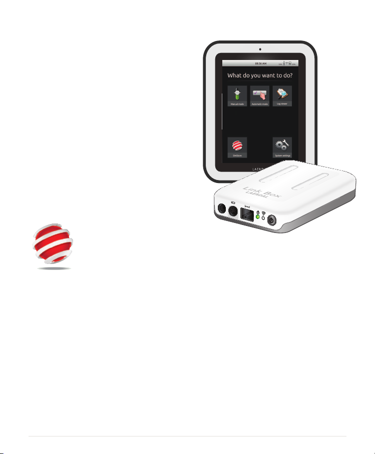
SIMPAD SYSTEM OVERVIEW
The SimPad System is an easy-to-use, wireless
tool that performs relevant medical simulation
training, including debrieng, in various user
settings. With its large, intuitive touch screen
design, SimPad is vir tually a “Pick up and Play”
experience, allowing you to deliver simulation-
based education, easily and efciently.
There are two ways to control simulations:
Automatic Mode and Manual Mode. This
allows you to customize simulations to meet your
specic needs.
The SimPad System is compatible with a broad
range of Laerdal products including manikins,
patient simulators, and task trainers as well as
standardized patients.
SIMSTORE
SimStore is the place to nd
quality educational content and
materials for users of all levels
and backgrounds.
SimPad
LAERDAL
http://www.mysimcenter.com
In SimStore you’ll nd resources for every step
of the simulation experience, from full curricula
and stand-alone scenarios, to building blocks like
trends, handlers, and multimedia. SimStore takes
efciency to a new level, allowing you to spend
less time developing or purchasing content and
more time improving educational outcomes.
Visit our SimStore to find:
• Immediate online access to world
wide, validated content
• Standardized and repeatable training
measures
• Easy search, nd, and pay navigation
• Flexibility to purchase only what you
need
4
Page 5

SIMPAD SYSTEM INCLUDES:
SimPad
LAERDAL
SimPad
English
Li-Ion Battery
LAERDAL
Link Box
AC adapter x 2
Manikin
Adapter Cable
Manikin Strap
Wrist Strap
USB Cable
SimPad Sleeve
• SimPad : Operator’s remote control
• Link Box: Connects to and controls the patient simulator
• Li-Ion Battery: Battery power for Link Box
• AC Adapter: Power and charger for SimPad and Link Box
• Manikin adapter cable: Connects Link Box to patient simulators
• Manikin Strap: Attaches Link Box and battery to patient simulator
• USB Cable: Attaches SimPad to PC for updates and downloads
• SimPad Wrist Strap
• SimPad Sleeve: Protective case for SimPad
5
Page 6
Link B
LAERDAL
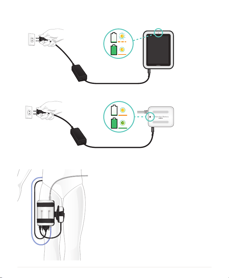
1. CHARGE THE BATTERY
• Connect SimPad to one of the AC adapters and plug into a wall outlet.
The battery is fully charged when the LED on SimPad shows a steady yellow light.
• Connect the Li-Ion battery to one of the DC adapters and plug into a wall outlet.
The battery is fully charged when the LED on the battery shows a steady green light.
2. CONNECT LINK BOX TO THE MANIKIN
• Connect the manikin cable to the Link Box.
• If it is an older version manikin, use cable adapter included
in the package.
LAERDAL
Link Box
ox
• Connect the BP tube (if applicable for this manikin) to the
BP tube input on the Link Box.
• Connect the Li-Ion battery to the Link Box. It is possible to
connect two batteries.
• If desirable, connect the DC adapter to the Link Box.
• Use the included manikin strap to attach the Link Box and
battery to the manikin.
6
Page 7
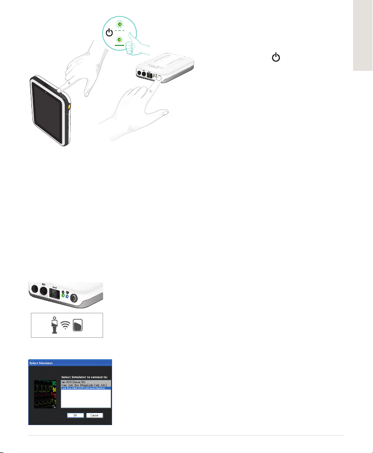
3. TURN ON LINK BOX AND SIMPAD
• Turn on both units by pressing the
ON button marked for at least
half a second.
• Release the button when the LED
starts blinking green. First start up
may take a few minutes.
• When the Link Box is ready, the
ON light will turn steady green.
• Follow the instructions on the
display to select language and other
preferences.
4. STARTING SIMPAD FOR THE FIRST TIME
The rst time SimPad is turned on, it will prompt for the following congurations:
• Select language
• Set time and date
• Enter SimPad name
• Enter Link Box name
All these congurations may be altered later.
5. CONNECTION BETWEEN SIMPAD AND LINK BOX
SimPad communicates with the Link Box using WiFi. When the units are turned on for the rst time
they will set up an ad hoc network called SimLink. If no other Link Boxes are visible on the default
SimLink network, the SimPad will pair with the Link Box, remember the pairing, and reconnect when
units are turned on again.
• Connection to SimPad is indicated on the Link Box with a blue light
in the WiFi LED.
• Connection to the Link Box is indicated in the upper right corner of
50% 50%
SimPad’s screen with a Manikin symbol.
English
6. CONNECTING A SIMULATED PATIENT MONITOR
• Ensure the monitor PC and the SimPad System are connected to
the same network. See “Connections” chapter for details on network
connections.
• Select the appropriate Link Box from the manikin connection menu.
• To minimize WiFi trafc, it is recommended to connect the patient
monitor to the Link Box using a direct network cable connection.
7
Page 8
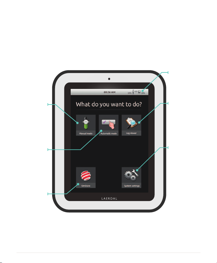
SIMPAD
SimPad is the new remote control for your medical training simulator.
Control simulation sessions directly from the touch screen by simply tapping the icons.
Find details on
battery status,
connection
and clock.
Run scenarios by
manually operating
the patient simulator
and registering
interventions.
Run pre-programmed
scenarios by simply
registering interventions.
Register SimPad
on SimStore or
synchronize with
SimStore.
SimPad
LAERDAL
Starting applications takes some seconds.
8
Select a log to
facilitate debrieng
with the Log Viewer.
Adjust display
brightness, clock
and more.
Page 9
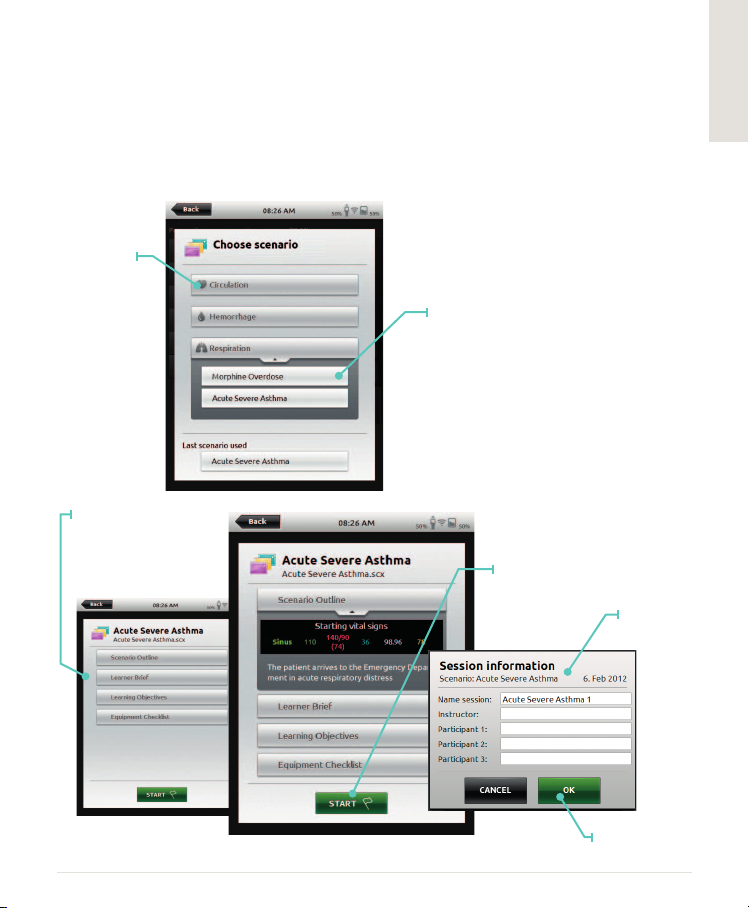
RUN AUTOMATIC MODE
When running a scenario in Automatic Mode, the only task required by the instructor is to
log the participant’s actions. These events logged, as well as the events detected by the patient
simulator, will drive the scenario forward. All events are registered in the log for post-event
debrieng and analysis.
Start by selecting a scenario from one of the scenario folders.
Folder
of scenarios.
Tap to open.
Select an
automatic
scenario.
Scenario description is
divided into sections.
Tap to open.
Press START to enter
session information.
Submit session
information.
English
Press OK
when ready.
9
Page 10
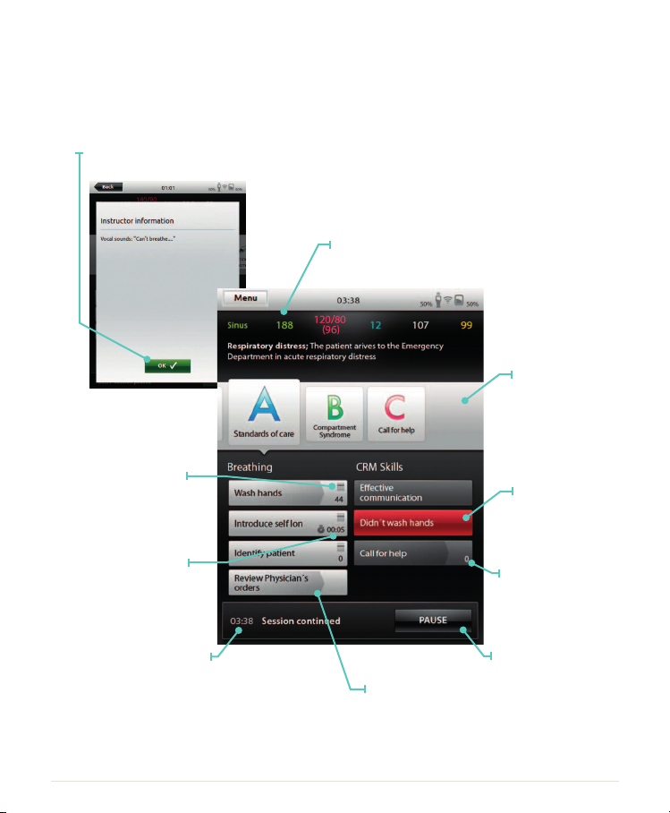
Review instructor information
and press OK to continue.
The 4-bar icon indicates that
registering the intervention
will launch pop-up.
Patient status
information
Categories of
interventions
Red button indicates
a critical event
Some interventions must
be performed within
a specic time. Timer
indicates remaining time.
Log
A shadow arrow on the
background indicates
an event that will cause
progress in scenario.
10
Counter keeps track
of how many times
an intervention has
been logged.
Pause scenario
Page 11
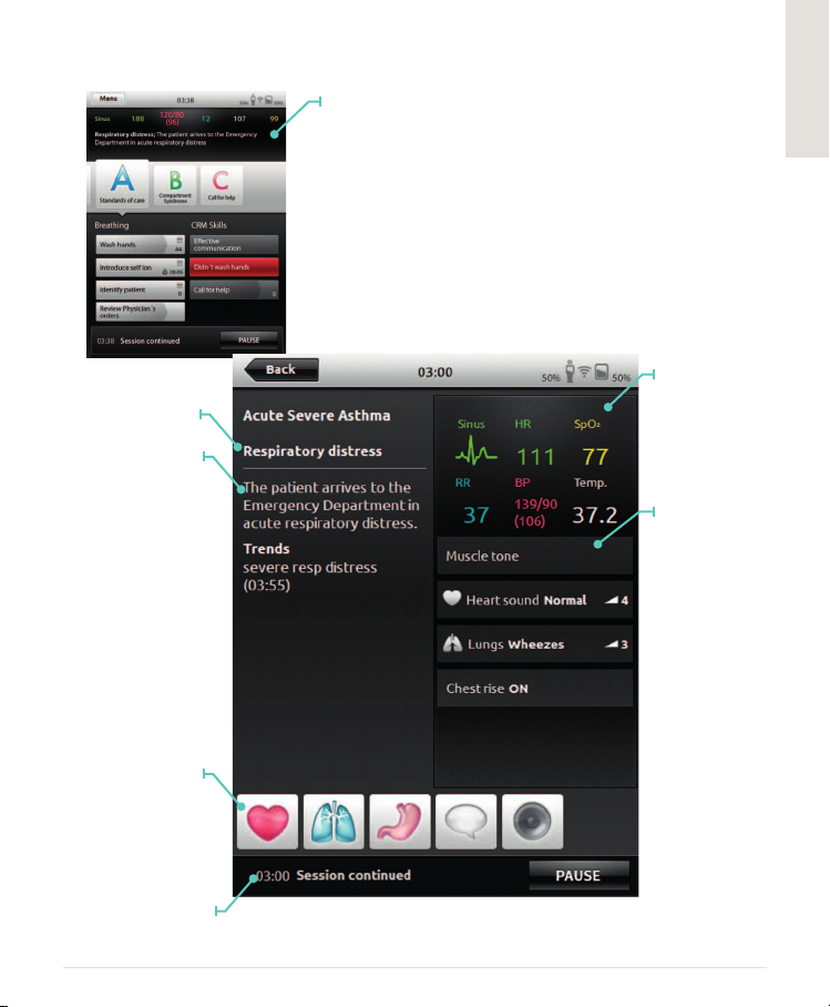
Current patient state
Patient state
information
Touch anywhere on patient
area to display more
patient state information.
Access to vital
signs adjustments
Abnormal parameter
values are displayed in
this area.
English
Select other
parameters
to adjust.
Log
11
Page 12

Toggle on / off
the amount
of information
displayed.
To end a session go to Menu
End session
View Log option will
open current session
log using Log Viewer.
Add comment
12
Page 13

RUN MANUAL MODE
When running a scenario in Manual Mode, the instructor’s task is to control the clinical state
of the patient simulator, as well as logging the participant’s actions. The instructor can plan
scenarios using predened themes that include various patient states.
Folder of Themes.
Tap to open.
Select Theme
for simulation.
Information about
session entered here
will be added to log.
English
Tap START
when ready.
13
Page 14

Waiting states
White arrow
indicates last
activated state.
Flag indicates
start state
Current state
Time since current
state was activated
Overview of the current
patient condition, vital signs
of patient.
Abnormal values
displayed in this area
Collapse mini-log
Select other
parameters to adjust
Tap to prepare a
state for activation
Activate all
parameters at once
Tap to expand
waiting state
Time since
session started
The expanded state
shows all parameters
in the queue, ready
to be activated.
End or pause session
Toggle on / off
shock activation
Register participant’s
interventions.
14
Set the
transition time
Page 15

REGISTERING INTERVENTIONS
Categories
of associated
interventions
Interventions of
the open category
Undo last
registration
Access to vital signs
adjustments
Interventions always
displayed
Counts interventions
logged
Add comment
English
15
Page 16

ADJUSTING PARAMETERS MANUALLY
Tap the large coloured
values in the main view,
(e.g. respiration rate) to
adjust the value.
Hold nger over
slider to access the
ne-adjustment
magnifying bubble.
Move nger
into the bubble
and adjust the
parameter in
small increments.
Create a new state with
the adjusted parameter.
Select a parameter
from the menu.
Update the currently
open waiting state.
Activate the
new value.
Tap to set desired
condition.
16
Page 17

VIEW LOG
Open Log Viewer from the home screen or when ending a session.
To end a session, go to Menu and press End session.
Go to Log Viewer
Continue where
you left off
Restart with
same scenario
Back to home screen
Add comment
Toggle on / off the amount
of information displayed.
English
17
Page 18

CONNECTING SIMPAD TO ANOTHER LINK BOX
SimPad can only be connected to one Link Box at a time. A Link Box can only be
connected to one SimPad at a time. SimPad will remember the Link Box it was last
connected to, and tr y to re-establish this connection the next time it is turned on.
To connect SimPad to a different Link Box, touch the connection information eld in
the upper right corner.
Select Connect to
another Link Box.
Select new Link Box or
choose to run without
CONNECTING ON A NETWORK
Link Box.
Out of the box, SimPad and Link Box will connect to the SimLink ad hoc network. They may
however be used on a wired Ethernet network, or a WiFi network. SimPad and Link Box may
also be connected directly to each other using a standard network cable.
1. CONNECTING ON WIRED ETHERNET NETWORK
Simply connect SimPad and Link Box to network outlets. The network
needs to have DHCP service. Connection by wire is indicated in the
50% 50%
upper right corner of SimPad. It is possible to be on a wired network
and a WiFi network simultaneously.
2. CONNECT TO A WIFI NETWORK
System settings – WiFi
18
Page 19

If you are moving the Link Box to another wireless network,
Link Box and SimPad must be connected to a wired network
or connected to each other by a network cable during the
connection process.
Select the desired WiFi
network from the list
and enter the network
password.
Then select the
device you want
to move to the
new network.
REGISTERING SIMPAD ON SIMSTORE
To register SimPad on SimStore, it needs to be connected to a network with internet, either via
wired Ethernet or a WiFi network.
• Touch the SimStore Icon
on the start screen.
• Select institution, enter
username and password
and touch register.
English
• SimPad identier will then
automatically be transferred
to SimStore and the device
is registered on the selected
account.
19
Page 20

SYNCHRONIZING SIMPAD WITH SIMSTORE
After SimPad has been registered on SimStore, the SimStore Icon on the start screen becomes a
Synchronize selection. Synchronize will download scenarios assigned to this SimPad on SimStore.
Administration of the SimPad and purchasing of scenarios on SimStore must be done from a PC.
PATIENT MONITOR
SimPad System can work with a Laerdal Simulated Patient Monitor. The patient monitor can show
ECG, SpO2, BP, Respiration rate, and Temperature from the SimPad.
The Monitor software needs to connect to the desired Link Box through a network connection,
wired or wireless.
When the PC is set up on the same network as the Link Box, start the Patient Monitor software on
the PC and select the desired Link Box from the selection dialogue.
The monitor software will remember its last connection, and try to reconnect to the same Link Box
the next time it is started.
To change to another Link Box, select “Connection Settings” from the Main Setup menu.
20
Page 21

THEME EDITOR
The Theme Editor is a PC software tool for creating Themes for the SimPad system. The
Theme Editor allows you to easily make new Themes with States and Interventions.
The Theme Editor can be loaded from www.laerdal.com/simpad.
SIMDESIGNER
SimDesigner is a PC software tool for creating Scenarios for the SimPad System. SimDesigner
allows you to make new Scenarios with States and Interventions, Trends and Handlers.
SimDesigner can be loaded from www.laerdal.com/simpad.
TRANSFERRING LOGS, THEMES AND SCENARIOS TO / FROM A PC
Connect SimPad to the PC using the included USB cable.
• Save new Scenarios in
the Scenarios folder.
• Save new Themes in
the Themes folder.
• Upload logs from the
Logs folder.
Disconnect the USB cable from the SimPad when transfers are nished.
Note: If SimPad is turned off, the batter y can be charged from the USB connection.
This charging is slower than if it is connected to the included DC adapter.
English
21
Page 22

SOUND
VOCAL SOUNDS
Vocal sounds from the patient simulator such as crying, moaning etc. can be activated from
the SimPad directly or via Themes and Scenarios.
TALKING THROUGH THE MANIKIN
1. NO HEADSET
The Link Box has a microphone input where you can plug in a standard computer micro-
phone or another sound source. When only this microphone is plugged in, the input from
the microphone will be routed to the manikin.
2. HEADSET
Alternatively a headset can connect to SimPad to create two-way communication between
the operator and the simulator and surroundings.
Plug an analogue headset (4 pin jack) into the SimPad. The microphone of the headset will
now be routed to the manikin. If a microphone is connected to the Link Box as in alternative
one, this microphone will now be routed to the headset.
The yellow button on the SimPad can be congured in the Preferences menu to enable and
disable the input from the headset.
The headset output on the Link Box duplicates the sound to the manikin. It can be used to
improve the sound by adding additional speakers around the manikin.
22
Page 23

LAERDAL LI-ION BATTERY
It is possible to connect two Laerdal Li-Ion batteries to the
Link Box.
When the Link Box is powered on, the batteries are discharged
in parallel. The remaining capacity in each battery will be displayed
in the SimPad.
BATTERY CHARGING
The batteries can be charged through the Link Box when the Link Box power is turned off and
the Link Box is connected to the AC adapter.
During charging, the Link Box ON indicator will blink with a yellow light, and the LED indicators
on the batteries will show a steady yellow. When the batteries are fully charged, voltage to the
batteries will be turned off and the indicator on the Link Box will show steady yellow.
English
LAERDAL
Battery 1
Battery 2
Alternatively, a battery can be charged by connecting it directly to the AC adapter.
During charging, the LED indicator on the battery will show a steady yellow. When the battery
is fully charged, the LED indicator shows steady green.
WARNINGS: Do not use the Laerdal Li-Ion Battery for other purposes than specied.
Use only the AC charger adapter supplied with the product.
Do not use the battery in temperatures above what is specied in this Directions for Use.
Do not heat or incinerate. Do not crush the battery. Do not short circuit the battery contact.
Do not immerse in water. The battery must be recycled and disposed of in accordance with
local rules.
23
Page 24

SAFETY INSTRUCTIONS
For your protection please, read these safety
instructions completely before connecting
the equipment to the power source.
Carefully observe all warnings, precautions
and instructions both on the apparatus and
in these operating instructions. Retain this
manual for future reference.
USER ENVIRONMENT
Protection against dust and moisture ac-
cording to IP 22. Do not use this product at
altitudes higher than 3000m asl. Do not use
the product in ambient temperatures above
35°C (95°F) and below 0°C (32°F).Relative
humidity (RH) must be between 10% to 90%.
WATER AND MOISTURE
Do not operate the apparatus under or near
water—for example near a bathtub, kitchen
sink, or laundry tub, in a wet basement, near
a swimming pool or in other areas with high
humidity.
• Never install jacks for communication
cables in wet locations.
• Do not operate the product with wet
hands.
CLEANING
Unplug the apparatus from communication
lines, mains power outlet or any power
source before cleaning or polishing. Do not
use liquid cleaners or aerosol cleaners. Use
a lint-free cloth lightly moistened with water
for cleaning the exterior of the apparatus.
LIGHTNING
Never use this apparatus, or connect/disconnect communication cables or power cables
during lightning storms.
DUST
Do not operate the apparatus in areas with
a high concentration of dust.
SERVICING
Do not attempt to service the apparatus
yourself. Opening or removing covers may
expose you to dangerous voltages or other
hazards, and will void the warranty. Refer all
servicing to qualied ser vice personnel.
INTERNAL BATTERY IN SIMPAD
CAUTION
If the internal battery packs in SimPad is
mishandled, the battery pack can burst,
cause a re or even chemical burns.
Observe the following cautions:
• Use only the SimPad battery with
SimPad.
• Do not expose to high temperatures,
such as in direct sunlight or in a car
parked in the sun.
• Replace only with the same type of
battery.
• Be sure to charge SimPad using only
the supplied battery charger or a
recommended charging device that
can charge the batteries.
• Keep SimPad dry.
• Dispose of used battery pack promptly
and according to local legislations.
DANGER
• Do not disassemble, crush, puncture,
or short external contacts or and do
not allow metal objects to come into
contact with the battery terminals.
• Do not try to repair the batter y, it may
cause explosion.
• Do not incinerate or dispose of in re,
the battery may explode or release
toxic materials.
• Do not dispose of in water.
• Do not handle damaged or leaking
Li-Ion batteries.
24
Page 25

POWER CONNECTION AND HAZARDOUS
VO LTAG E
The product or its accessories may have a hazardous voltage inside.
• Never attempt to open this product, or any
peripherals connected to the product, if this
action requires a tool.
• This product should always be powered from
an earthed power outlet.
• If any par ts of the product have visual damage,
never attempt to connect main power, or any
other power source, before consulting service
personnel.
• Route the power cord to avoid it being walked
on or pinched by items placed upon or against
it. Pay par ticular attention to the plugs, recepta-
cles and the point where the cord exits from
the apparatus.
• Do not tug the power cord.
• If the provided plug does not t into your
outlet, consult an electrician.
INDUSTRY CANADA RULES
This device complies with RSS-210 of the Industry
Canada Rules. Operation is subject to the following
two conditions: (1) This device may not cause harmful interference, and (2) this device must accept any
interference received, including interference that may
cause undesired operation.
Ce dispositif est conforme à la norme CNR-210
d'Industrie Canada applicable aux appareils radio
exempts de licence. Son fonctionnement est sujet
aux deux conditions suivantes: (1) le dispositif ne
doit pas produire de brouillage préjudiciable, et (2)
ce dispositif doit accepter tout brouillage reçu, y
compris un brouillage susceptible de provoquer un
fonctionnement indésirable.
ACCESSORIES
Use only accessories specied by the manufacturer,
or sold with the apparatus.
The RJ-45 jack is not used for telephone line
connection.
FCC STATEMENT
This device complies with part 15 of the FCC r ules.
Operation is subject to the following two conditions:
(1) This device may not cause harmful interference
(2) This device must accept any interference
received, including interference that may cause
undesired operation.
This equipment has been tested and found to
comply with the limits for a Class B digital device,
pursuant to Part 15 of the FCC rules. These limits
are designed to provide reasonable protection
against harmful interference in a residential installation. This equipment generates, uses, and can radiate
radio frequency energy and, if not installed and used
in accordance with the instructions, may cause harmful interference to radio communications. However,
there is no guarantee that interference will not occur
in a particular installation. If this equipment does
cause harmful interference to radio or television
reception, which can be determined by turning the
equipment off and on, the user is encouraged to try
to correct the interference by one or more of the
following measures:
• Reorient or relocate the receiving antenna.
• Increase the separation between the equipment
and receiver.
• Consult the dealer or an experienced radio/TV
technician for help.
The use of shielded I/O cables is required when
connecting this equipment to any and all optional
peripheral or host devices. Failure to do so may
violate FCC rules.
IMPORTANT Changes or modications not
covered in this manual must be approved
in writing by the manufacturer’s Regulatory En-
gineering Department. Changes or modications
made without written approval may void the
user’s authority to operate this equipment.
English
25
Page 26

CANADIAN ICES-003 STATEMENT
This Class B digital apparatus meets all of the
requirements of the Canadian InterferenceCausing Equipment Regulations.
Cet appareil numérique de la classe B
respecte toutes les exigences du Règlement
sur le matériel brouilleur du Canada.
CE COMPLIANCE STATEMENT
Laerdal Medical AS hereby declares that
when carr ying the CE-mark, this product is in
compliance with the essential requirements
and other relevant provisions of Directive
1999/5/EC.
Li-Ion batteries should be recycled.
Li-Ion
WEEE
Waste Electrical and Electronic Equipment
This appliance is marked according to the
European directive 2002/96/EC on Waste
Electrical and Electronic Equipment (WEEE).
By ensuring this product is disposed of
correctly, you will help prevent potential
negative consequences for the environment
and human health, which could otherwise be
caused by inappropriate waste handling of this
product.
The symbol on the product, or on the documents accompanying the product, indicates
that this appliance may not be treated as
household waste. Instead it shall be handed
over to the applicable collection point for
the recycling of electrical and electronic
equipment. Disposal must be carried out
in accordance with local environmental
regulations for waste disposal.
For more detailed information about treatment,
recovery and recycling of this product, please
contact your local city ofce, your household
waste disposal service or Laerdal representative.
LIMITED WARRANTY
Please refer to the Laerdal Global Warranty
statement, and for more information see:
www.laerdal.com
Product specications are subject to change
without notice.
26
Page 27

SPECIFICATIONS
Operating temperature 0°C to +35°C (32°F to 95°F), Humidity 5 – 90% R.H. non-condensing
Storage temperature -20°C to +60°C (-4°F to +140°F)
IP Classication IP32
Cleaning Wipe units with a damp soft cloth with household soap water
SIMPAD
Size 158 x 126 x 25 mm (6,22” x 4,96”x 0,98”)
Weight 450 g (1 lb)
LCD display: High Resolution Color LCD display, 5.7”, 480 x 640 pixels
Battery type: Li-Ion 3.7V, capacity: 16 Wh
Battery time: 3 - 4 hours continuous use with 50% display brightness.
Battery charging: DC input 12V 0,7A max.
Charging time: 10 – 80%, approximately 50% / hour from DC input 80% - 100% , 1 hour
Communication WiFi 802.11b/g (2.4GHz). Ethernet 10/ 100 MB
USB OTG input, 5V 500 mA max
OPERATION: ON – OFF BUTTON:
Press for 0,5 seconds to turn unit on (LED start blinking green)
Short press while unit is on: Turn display on and off
Press 0,5 seconds to turn unit off (conrm on screen)
Auxiliary
Press and hold for more than 5 seconds to force unit off
AUXILIARY BUTTON: See Preferences menu to select function.
LED:
Unit off and charging: Blinking yellow light when charging, Steady yellow light when charged.
Unit starting and shutting down: Blinking green light.
Unit on: Steady green light
Power on when battery too low: Blinking red light (5 blinks)
Error, needs ser vice: Steady red light
button
ON / OFF
CONNECTIONS:
DC input: 9 – 15 V DC, 2 A max, + on center pin.
Ethernet: RJ45 connector
USB: USB on the go input / output.
Audio: 3,5 mm audio jack with TRRS input. Microphone on sleeve
(compatible with iPhone headset).
Audio
USB
Ethernet
English
LED
DC
27
Page 28

1
1
LINK BOX
Size 140 x 90 x 30 mm (5,51” x 3,54”x 1,18”)
Weight 200 g (0,44 lb)
Communication WiFi 802.11b/g (2.4GHz)
Ethernet 10/ 100 MB
OPERATION:
ON / OFF BUTTON:
1. Press for 0,5 seconds to turn unit on (LED start blinking green).
2. Press 0,5 seconds to turn unit off (conrm on screen).
3. Press and hold for more than 5 seconds to force unit off.
POWER LED:
1. Unit off and charging: Blinking yellow light when charging,
Steady yellow light when batteries charged.
2. Unit starting and shutting down: Blinking green light.
3. Unit on: Steady green light.
4. Error, needs service: Steady red light.
WIFI LED:
1. Connected to a network: Steady green.
2. Connected to a Link Box: Steady blue.
CONNECTIONS
DC input: 9 – 15 V DC, 3,3 A max, + on center pin.
Ethernet: RJ45 connector.
Future: Connector for future use.
Manikin: Power and signals to manikin. Pulse, sounds etc.
Battery #1: Connector for Laerdal Li-Ion Battery.
Blood Pressure: Cuff pressure input: 0 – 300 mm Hg.
USB: USB A input / output.
Audio in: 3,5 mm jack with TRS input. Line in or microphone level.
Audio out: 3,5 mm jack with TRS output. Line out level.
Battery #2: Connector for Laerdal Li-Ion Battery.
DC
Future
Ethernet
Power
LED
1
Battery Manikin Blood Pressure
USB
Audio out
Audio in
WiFi
LED
Battery
ON / OFF
28
Page 29

LI-ION BATTERY
Battery type Li-Ion, 4 cells
Cell type LIC18650-22PC
Voltage 7,2 V nominal
Capacity 4,4 Ah typical (32 Wh)
Size 98 x 78 x 28,1 mm (3,86” x 3,07” x 1,11”)
Weight 270 g (0.6 lb) approximately.
BATTERY CHARGING
Charging voltage input 9 – 15V DC, 1,6 A max
Charging method Constant Current + Constant Voltage
Constant current 1.33A typ.
Expected cycle life 700 cycles for ≥ 1400mAh (cell)
Charging time: 0 – 80 %: 30 % per hour
CHARGING INDICATOR
CONNECTORS
Connector tail for battery out and charging:
Pin out:
PIN DESCRIPTION
1 Battery data
2, 5 Battery +
3, 4, 6 Battery -
DC INPUT CONNECTOR FOR BATTERY CHARGING
Connector type: DC-plug receptacle with 2 mm center pin, + on center pin
Input voltage level: 9V – 15V DC
80% - 100%: 1 hour.
1. The charging indicator is only active when there is a charging voltage present.
2. Charging: Steady yellow light
3. Charged: Steady Green light.
(Front view of plug)
4 6
1 3
English
29
Page 30

SimPad System has the same ECG library as SimMan 3G and other Laerdal simulators.
The available rhythms and rhythm parameters may vary from simulator to simulator.
AVAILABLE ECG IN SIMPAD SYSTEM:
BASIC RHYTMS RATES
ADULT AND CHILD
RATES
INFANT
Sinus 20 - 200 20- 240
WPW 20 - 200 20- 240
Hyperkalemia 20 – 200 20- 240
Long QT 20 - 200 20- 240
Ischemia 20 - 200 20- 240
Inferior AMI, ST elevation 20- 200 20- 240
LBBB 20- 200 20- 240
RBBB 20- 200 20- 240
Atrial Tachycardia 140 – 260 90 - 320
SVT 140 – 260 90 - 320
Atrial Flutter 75, 100, 150 75, 100, 150
Atrial Fibrillation 50 - 240 50 - 240
Junctional 40 - 220 40 - 220
1° AV-Block 20 – 135 20 – 135
2° AV Block type #1 3:2,4:3, 5:4 3:2,4:3, 5:4
2° AV Block type #2 4:3, 3:2, 2:1 4:3, 3:2, 2:1
3° AV Block 10 - 50 20 - 100
Ventricular Tachycardia (VT) 120 - 240 120 - 320
Torsade de pointes 180 180
Idioventricular 10 - 100 14 - 100
V. Fib. 0.1 – 1 mV 0.1 – 1 mV
Asystole
Ventricular Standstill
Ventricular Pacemaker 50 – 150 50 – 150
EXTRASYSTOLES
PVC
PVC RonT
Couplet PVC
PAC/PJC
PVC
PVC RonT
Couplet PVC
PAC/PJC
PVC
PVC RonT
Couplet PVC
30
Page 31

BLOOD PRESSURE
Pressure range 0 - 300 mmHg
Accuracy +/- 4 mmHg
Calibration Pressure sensor must be calibrated to sphygmomanometer. See Preferences menu.
PULSE
Available pulses Carotid, Brachial, Radial and Umbilical (SimNewB)
Palpated BP Radial pulse turns off at systolic BP.
Only 3 pulses can be palpated simultaneously. (Power considerations).
Brachial pulse turns off at 20 mmHg, to prevent noise generation in auscultation area.
ADULT
MANIKIN
CHILD
MANIKIN
INFANT
MANIKIN
Default Blood Pressures (mmHg) 120/80 100/70 94/66
ADULT PULSES ARE AUTOMATICALLY ADJUSTED TO BP AS FOLLOWS:
SYSTOLIC BP CAROTID PULSE RADIAL/BRACHIAL PULSE
>= 88 Normal Normal
< 88 Normal Weak
< 80 Normal Absent
< 70 Weak Absent
< 60 Absent Absent
Infant pulses are automatically set to absent when Systolic BP is below 10 mm Hg. Otherwise Infant pulses are normal.
31
Page 32

HEART SOUNDS:
Heart sounds are synchronized to ECG.
HEARTSOUNDS: ADULT
Normal
Aortic
Stenosis
Austin Flint Murmur
Mitral Valve Prolapse
Systolic Murmur
Diastolic Murmur
Friction Rub
Opening Snap @70 msec
Stills Murmur
Atrial Septal Defect (ASD)
VentricularSeptal Defect (VSD)
Pulmonary Stenosis
LUNG SOUNDS:
Lung sounds are synchronized to breathing rates, adjustable from 0 – 60 breaths / min.
LUNG SOUNDS: ADULT
Normal Breath Sounds
Fine Crackles
Coarse Crackles
Pneumonia
Wheeze
Stridor
Pleural Rub
Rhonchi
MANIKIN
• • •
• • •
• • •
• • •
•
•
•
MANIKIN
• • •
• • •
• • •
• • •
• • •
• • •
•
• • •
CHILD
MANIKIN
•
• •
• •
• •
CHILD
MANIKIN
INFANT
MANIKIN
INFANT
MANIKIN
•
32
Page 33

BOWEL SOUNDS:
BOWEL SOUNDS: ADULT
Normal
Borborygmus
Hyperactive
Hypoactive
Fetal Normal 140 BPM
Fetal Brady 100 BPM
Fetal Tachy 200 BPM
No sound
VOCAL SOUNDS:
Vocal sounds are adjusted for age and gender of manikin.
MALE MANIKIN FEMALE MANIKIN CHILD MANIKIN INFANT MANIKIN
Vomit Vomit Vomit Cry
Cough Cough Cough Cough
Moan Moan Moan Content
SOB Breathing SOB Breathing SOB Breathing Hickups
Scream Scream Scream Scream
Ye s Ye s Ye s
No No No
User dened vocal sounds can replace the included vocal sounds.
Sound format for user dened sound les must be raw format 16KHz, 16 bits signed, little endian.
MALE
ADULT
FEMALE
CHILD
MANIKIN
INFANT
MANIKIN
• • • •
• • • •
• • • •
• • • •
•
•
•
• • • •
33
Page 34

34
Page 35

English
35
Page 36

www.laerdal.com
© 2012 Laerdal Medical AS. All rights reserved
20-05299 Rev A
 Loading...