


WS-7394U
Wireless 433 MHz
Weather Station
Instruction Manual
FCC DISCLAIMER
FCC ID: OMO-01RX (Receiver), OMO-01TX (transmitter)
This device complies with part 15 of the FCC rules. Operation is subject to the following two conditions:
(1)This device may not cause harmful interference.
(2)This device must accept any interference received, including inter
ference that may cause undesired operation.
R
Contents
Language Page
English 2
French 18
Spanish 36
TABLE OF CONTENTS
Topic Page
Inventory of Contents/ Additional Equipment 3
About WWVB 3
Quick Set Up Guide 4
Detailed Set Up Guide
Battery Installation 5
Start Up Sequence 6
Explanation of LCD Information 7
Function Key Layout 8
Program Mode
Overview of Programming Sequence 8
LCD Contrast Setting 8
Time Zone Setting 9
DST ON/OFF Setting 9
Radio-controlled Time ON/OFF Setting 10
12/24-hour Time Mode Setting 10
Setting the Time/Date Manually 11
Temperature Measuring Units (˚F/˚C) 12
Air Pressure Measuring Units (inHg/hPa) 13
Relative Pressure Setting 13
Forecast Sensitivity Setting 14
Features and Operation
Minimum/Maximum Temperature/Humidity 14
Multiple Remote Temperature/Humidity Sensors 15
Comfort Icon 16
Weather Forecast and Pressure Trend Indicators 16
Weather Icons 17
Weather Tendency Arrows 17
Barometric Air Pressure Reading 1 8
Air Pressure History Bar Chart 18
Mounting 19
Maintenance and Care 20
Troubleshooting Guide 20
Specifications 21
Warranty Information 22
P.2
GB
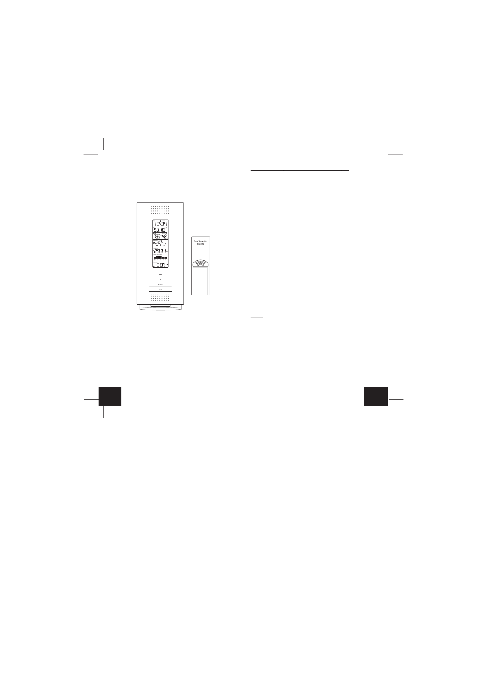
INVENTORY OF CONTENTS
1. WS-7394U-indoor weather station
2. TX6U-remote temperature (temperature/humidity) sensor
3. Instruction manual and warranty card
ADDITIONAL EQUIPMENT (not included)
1. Five fresh AA 1.5V alkaline batteries.
2. One wall-mounting screw (optional)
For more information about WWVB please see the NIST website at
http://www.boulder.nist.gov/timefreq/stations/wwvb.htm
QUICK SET-UP GUIDE
Hint:
Use good quality Alkaline Batteries and avoid rechargeable
batteries.
1. Have the indoor weather station and remote temperature sensor 3
to 5 apart.
2. Batteries should be out of both units for 15 minutes.
3. Place the batteries into the remote temperature sensor first then
into the indoor weather station.
(All remote temperature sensors must be started before the indoor
weather station)
4. DO NOT PRESS ANY BUTTONS FOR 15 MINUTES.
In this time the indoor weather station and remote temperature sensor
will start to talk to each other and the indoor weather station will show
both the indoor temperature and humidity and the outdoor temperature.
If the indoor weather station does not display all values after the 15
minutes please retry the set up as stated above. After all values are
displayed for 15 min utes y ou can place your remote temperature sensor outdoors and set your time.
The remote temperature sensor should be placed in a dry, shaded
area. The remote temperature sensor has a range of 330 feet. Any
walls that the signal will have to pass through will reduce distance . An
outdoor wall or window will have 20 to 30 feet of resistance and an
interior wall will have 10 to 20 feet of resistance. Your distance plus
resistance should not exceed 330 ft. in a straight line.
ABOUT WWVB (radio-controlled time)
The NIST (National Institute of Standards and Technology-Time and
Frequency Division) radio station, WWVB, is located in Ft. Collins,
Colorado and transmits the exact time signal continuously throughout
the United States at 60 kHz. The signal can be received up to 2,000
miles away through the internal antenna in the indoor weather station.
However, due to the nature of the Earth’s Ionosphere, reception is
very limited during da ylight hours. The indoor weather station will search
for a signal every night when reception is best. The WWVB radio station derives its signal from the NIST Atomic clock in Boulder, Colorado.
A team of atomic physicists continually measure every second of every day to an accuracy of ten billionths of a second a day. These
physicists have created an international standard, measuring a second as 9,192,631,770 vibrations of a Cesium 133 atom in a vacuum.
GB
P.3
NOTE:
Fog and mist will not harm your remote temperature sensor
but direct rain must be avoided.
To complete the set up of your indoor weather station after the 15
minutes have passed please follow the steps in the Detailed Set Up
Guide.
Note:
The remote temperature sensor transmits a signal every 3
minutes; after the batteries have been installed, the indoor weather
station will search for the signal for a duration of 5 minutes. If there is
no temperature reading in the OUTDOOR LCD after 5 minutes, make
sure the units are within range of each other, or repeat the battery
installation procedure.
GB
P.4
DETAILED SET-UP GUIDE
I. Battery Installation
Batteries will fit tightly. To avoid start-up problems, make sure that the
batteries do not spring free. Also be sure to insert alkaline batteries
into the remote temperature sensor first, then the indoor weather station.
Initial set up should be done with the remote temperature sensor and
indoor weather station in the same room. The units should be permanently mounted only after the signal reception has been verified.
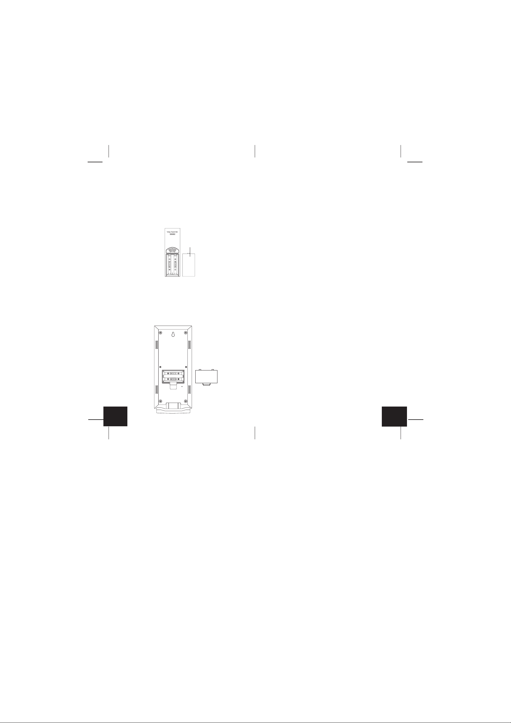
A. Remote Temperature and Humidity Sensor
Battery Cover
1. Remove the mounting bracket. The bracket snaps on and off easily.
2. Remove the battery cover, by sliding the cover down.
3. Observing the correct polarity install 2 AA batteries. The batteries
will fit tightly (to avoid start-up problems make sure they do not
spring free).
4. Replace the battery cover by sliding upwards. Be sure battery cov er
is on securely.
B. Indoor Weather Station
1. Remove the battery cover (the cover has white writing on it).
2. Observe the correct polarity, and install two Alkaline AA batteries.
3. Do not press any buttons for at least ten minutes. If a button is
pressed before the indoor weather station has received infor mation from the TX6U sensor, no data will be received from that sensor until reset.
4. Replace the battery cover.
II. Start Up Sequence
A. Initial Start
1. Immediately after the batteries have been installed the LCD will
completely light up for a brief moment.
2. All information will then appear in normal mode, with “12:00” as the
default time and “WE.1” as the default date (2004 as the year).
3. The indoor temperature and humidity, and barometric air pressure
(as 29.91 inHg relative RH) will also be displayed.
4. There is a “satellite” icon that appears in the bottom portion of the
LCD, to the left of the outdoor temperature- this icon informs the
user that the indoor weather station is looking for signals from the
remote temperature sensor. Within five minutes the remote temperature should be displayed-if not, remov e batteries from all units
and repeat battery installation, the remote temperature sensor first,
then the indoor weather station.
B. WWVB Reception
1. Once the batteries are installed in the indoor weather station it will
automatically search for the WWVB signal. If it receives a good
signal (which is unlikely during daylight hours in most locations),
the WWVB reception indicator (looks like a tower icon) will flash.
The indoor weather station requires five full minutes of good reception to successfully capture the signal and set to the correct hour,
minute, second, month, day and year. If the signal reception is not
successful within ten minutes, the signal search will be cancelled
and will automatically resume every two hours until the signal is
successfully captured.
2. The signal is sent from Ft. Collins, Colorado only and is similar to
an AM radio signal. Atmospheric interferences such as stor ms,
sunspots, and even sunlight will cause the signal to not travel as
far.
3. To maximize reception, place the indoor weather station in a window facing Colorado, at least six feet from any electrical source
(computers, televisions, refrigerators, etc.). Do not move the indoor weather station while it is searching for the signal.
4. The time and date can be manually set. Once the signal is captured,
it will override any time and date set to the time zone selected.
GB
P.5
P.6
GB
5. Once the time and date are set, the indoor weather station will
conduct a search every night at midnight and correct to the accurate time and date (Daylight Saving Time is automatic). If the signal
has been received in the past 24 hours, the reception indicator will
be displayed.
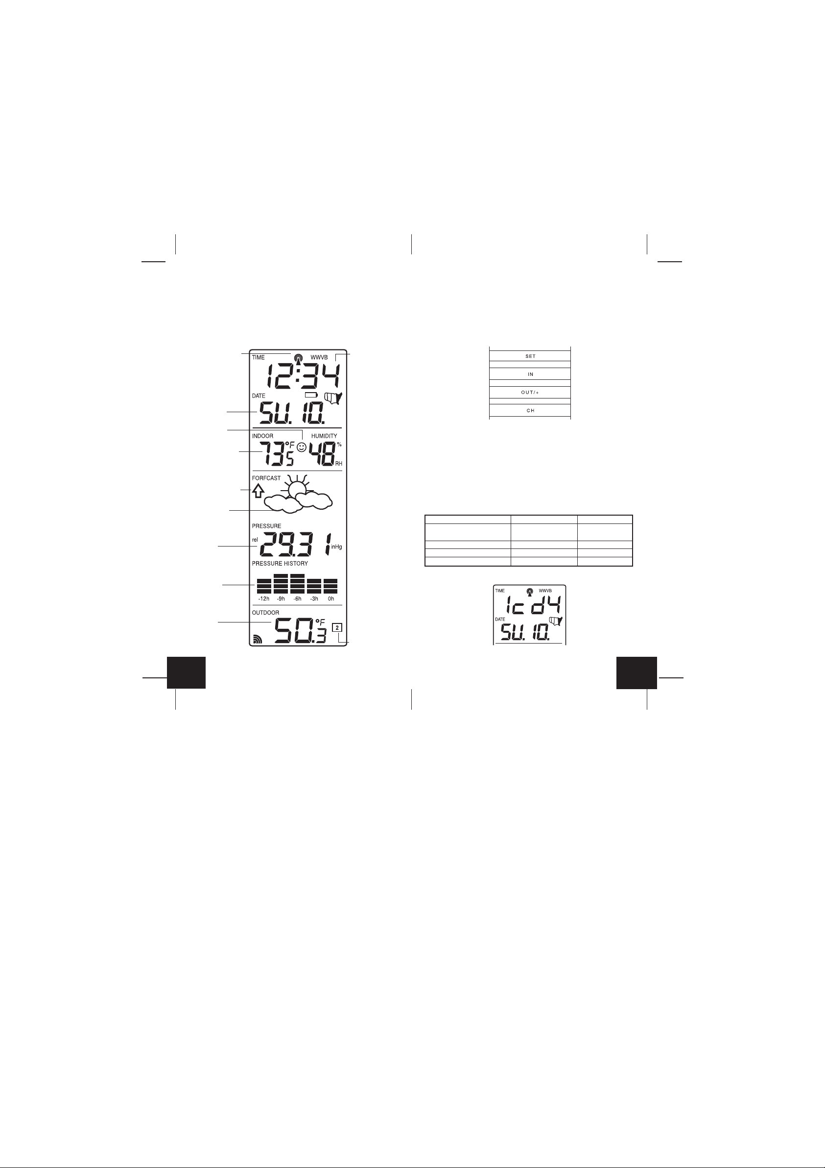
III. Explanation of LCD Information
A. The below picture highlights the LCD features.
WWVB Reception
Indicator
Date Display
Radio-controlled
time
B. There are many different modes the indoor weather station can be
set to. The LCD shown is the normal operating mode, and your
actual data shown will be different based on your local settings and
conditions.
IV.Function Key Layout
A. The below picture shows the four function keys used in program-
ming and operation of your indoor weather station
Comfort Icon
Indoor T emperature
Humidity Display
Air Pressure Trend
Indicator
Forecast Icon
Barometric Air
Pressure
12-hour Air
Pressure History
Outdoor
Temperature Display
GB
P.7
Remote Sensor
Number (Up to 3
Total)
V. Program Mode
The program mode is laid out in a manner that allows you to program
each function separately, or you can follow the instructions entirely to
program the indoor weather center. Complete programming is usually
done for the initial set-up, and will require y ou to skip step 1,2 and 3 of
each programming section. The programming mode can be exited at
any time by either pressing the “CH” button, or waiting for the 15-second time-out to take effect.
A. Overview of programming mode sequence
1. LCD Contrast 2. Time Zone 3. DST ON/OFF
4. Radio-controlled 5. 12/24-hour 6. Hour
Time ON/OFF time mode
7. Minute 8. Year 9. Month
10. Date 11. ˚F/˚C 12. inHg/hPa
13. Relative pressure setting 14. Forecast sensitivity
B. LCD Contrast Setting
1. Press and hold the “SET” button for five seconds.
GB
P.8
2. “lcd” will appear at the top of the display and a number will flash
next to it.
3. Press and release the “OUT/+” button to select the desired LCD
contrast setting.
4. Press and release the “SET” button to confirm the LCD contrast
setting and continue to the Time Zone setting.
C. Time Zone Setting
1. Press and hold the “SET” button for five seconds.
2. “lcd” will appear at the top of the display and a number will flash
next to it.
3. Press and release the “SET” button once more to advance to the
Time Zone setting.
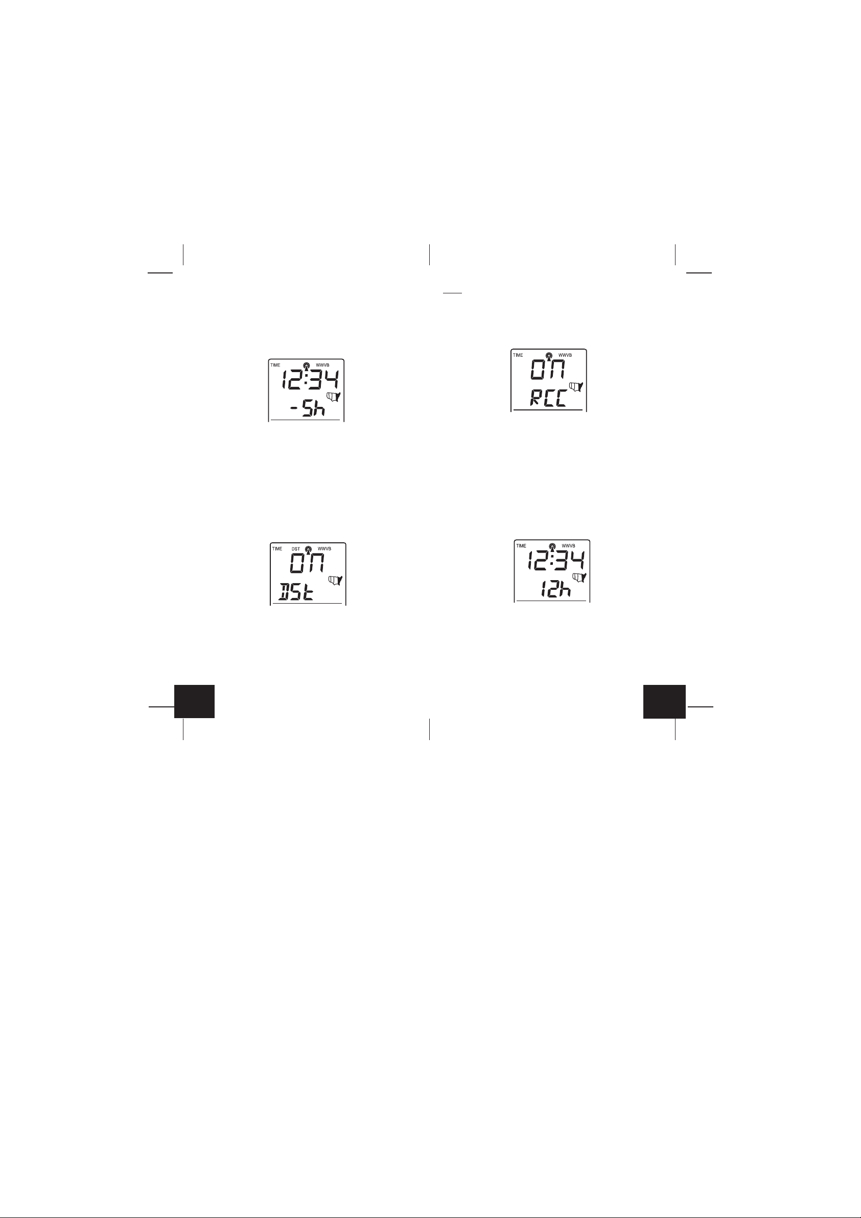
4. A number will flash to the left of the letter “h” at the top of the displa y
just below the time display.
5. Press and release the “OUT+” button to select the desired time
zone.
6. Press and release the “SET” button to confirm the Time Zone setting and continue to the DST ON/OFF setting.
Note:
Some locations (Arizona and par ts of Indiana) do not follow
Daylight Saving Time.
6. Press and release the “SET” button to confir m the DST ON/OFF
setting and continue to the Radio-controlled Time ON/OFF setting.
E. Radio-controlled Time ON/OFF Setting
1. Press and hold the “SET” button for five seconds.
2. “lcd” will appear at the top of the display and a number will flash
next to it.
3. Press and release the “SET” b utton three more times to adv ance to
the Radio-controlled time ON/OFF setting.
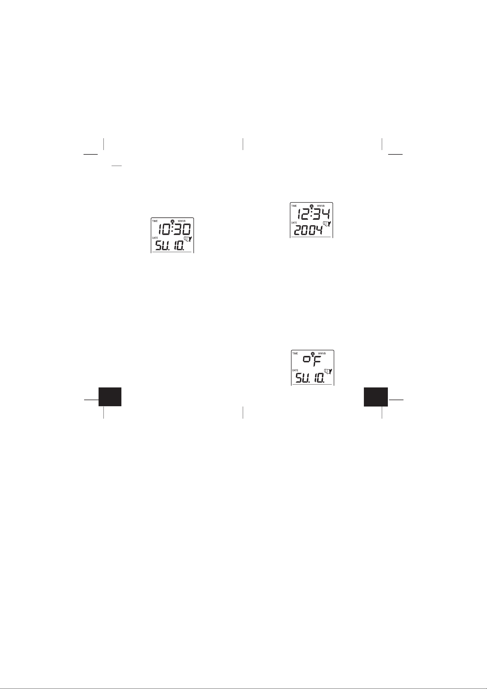
4. “RCC” will appear above the indoor temperature/humidity display
and “ON” or “OFF” will flash above that.
5. Press and release the “OUT/+” button to select Radio-controlled
time ON/OFF setting.
6. Press and release the “SET” b utton to confirm the Radio-controlled
time ON/OFF setting and continue to the 12/24-hour Time Mode
setting.
D. DST ON/OFF Setting
1. Press and hold the “SET” button for five seconds.
2. “lcd” will appear at the top of the display and a number will flash
next to it.
3. Press and release the “SET” button twice more to advance to the
DST ON/OFF setting.
4. “DST” will appear above the indoor temperature/humidity display
and “ON” or “OFF” will flash above that.
5. Press and release the “OUT/+” button to select DST ON/OFF.
GB
P.9
F. 12/24-hour Time Mode
1. Press and hold the “SET” button for five seconds.
2. “lcd” will appear at the top of the display and a number will flash
next to it.
3. Press and release the “SET” b utton four more times to advance to
the 12/24-hour time mode setting.
4. “12h” or “24h” will flash above the indoor temperature/humidity
display.
5. Press and release the “OUT/+” button to select 12 or 24-hour time
mode.
GB
P.10
Note:
In 12h mode “PM” will appear to the left of the time during PM
hours. If the time is not within the PM hours nothing will be displa yed.
Be sure to set the time to the correct AM/PM time to ensure automatic
reception.
6. Press and release the “SET” button to confirm the 12/24-hour time
mode setting and continue to the Hour setting
G. Setting The Hour Manually
The WWVB signal will override any manual set time and date
information. The time will be based on the time zone selected.
1. Press and hold the “SET” button for five seconds.
2. “lcd” will appear at the top of the display and a number will flash
next to it.
3. Press and release the “SET” button five more times to advance to
the Manual Hour setting.
4. The hour will begin to flash at the top of the display.
5. Press and release the “OUT/+” button to select the desired hour.
6. Press and release the “SET” button to confirm the hour setting and
continue to the Minute setting.
H. Setting The Minutes Manually
1. Press and hold the “SET” button for five seconds.
2. “lcd” will appear at the top of the display and a number will flash
next to it.
3. Press and release the “SET” button six more times to advance to
the Manual Minutes setting.
4. The minutes will begin to flash at the top of the display.
5. Press and release the “OUT/+” b utton to select the desired minutes.
6. Press and release the “SET” button to confir m the minutes and
continue to the Year setting.
I. Setting The Y ear Manually
1. Press and hold the “SET” button for five seconds.
2. “lcd” will appear at the top of the display and a number will flash
next to it.
3. Press and release the “SET” button seven more times to advance
to the Manual Year setting.
4. The year will begin to flash below the time display.
5. Press and release the “OUT/+” button to select the desired year.
6. Press and release the “SET” button to confirm the year and continue to the Month setting.
J. Setting The Month Manually
1. Press and hold the “SET” button for five seconds.
2. “lcd” will appear at the top of the display and a number will flash
next to it.
3. Press and release the “SET” b utton eight more times to adv ance to
the Manual Month setting.
4. The Month will begin to flash below the time display.
5. Press and release the “OUT/+” button to select the desired month.
6. Press and release the “SET” button to confirm the month and continue to the Date setting.
K. Setting The Date Manually
1. Press and hold the “SET” button for five seconds.
2. “lcd” will appear at the top of the display and a number will flash
next to it.
3. Press and release the “SET” button nine more times to advance to
the Manual Date setting.
4. The date will begin to flash below the time display.
5. Press and release the “OUT/+” button to select the desired date.
6. Press and release the “SET” button to confirm the date and continue to the Temperature Measuring Units setting.
L. Temperature Measuring Units Selection (˚F or ˚C)
GB
P.11
1. Press and hold the “SET” button for five seconds.
P.12
GB
2. “lcd” will appear at the top of the display and a number will flash
next to it.
3. Press and release the “SET” button ten more times to advance to
the Temperature Measuring Units setting.
4. ˚F or ˚C will flash at the top of the display.
5. Press and release the “OUT/+” button to select the desired temperature-measuring unit.
6. Press and release the “SET” button to confirm the temperaturemeasuring unit and continue to the Air Pressure Measuring Units
setting.
M. Air Pressure Measuring Units Selection (inHg/hPa)
1. Press and hold the “SET” button for five seconds.
2. “lcd” will appear at the top of the display and a number will flash
next to it.
3. Press and release the “SET” b utton eleven more times to advance
to the Air Pressure Measuring Units setting.
4. inHg or hPa will flash at the top of the display.
5. Press and release the “OUT/+” b utton to select the desired air pressure-measuring unit.
6. Press and release the “SET” button to confirm the air pressuremeasuring unit and continue to the Relative Pressure setting.
N. Relative Pressure Setting
1. Press and hold the “SET” button for five seconds.
2. “lcd” will appear at the top of the display and a number will flash
next to it.
3. Press and release the “SET” button twelve more times to advance
to the Relative Pressure setting.
4. The barometric air pressure will flash in the middle of the display,
just below the forecast icon
5. Press and release the “OUT/+” or “IN” button to select the desired
air pressure-measuring unit.
6. Press and release the “SET” button to confirm the relativ e pressure
setting and continue to the Forecast Sensitivity setting.
O. Forecast Sensitivity Setting
1. Press and hold the “SET” button for five seconds.
2. “lcd” will appear at the top of the display and a number will flash
next to it.
3. Press and release the “SET” b utton thirteen more times to advance
to the Forecast sensitivity setting.
4. The two air pressure tendency arrows will begin flashing on either
side of the forecast icon and a flashing number will appear under
the forecast icon.
5. Press and release the “OUT/+” b utton to select the desired f orecast
sensitivity setting.
Note:
Barometric air pressure is usually repor ted as “relative air
pressure”. This reading is based on the combination of absolute air
pressure and altitude. In gener al, an increase in altitude will result in a
decrease in air pressure. Relative air pressure will make readings in
nearby locations relative to each other to allow f or proper forecasting.
The absolute air pressure reading in the Weather Center cannot be
calibrated, only the relative air pressure.
6. Press and release the “SET” button to confirm the forecast sensi-
tivity setting.
THE MANUAL SETTING IS NOW COMPLETED
FEATURES AND OPERATIONS
A. Minimum and Maximum Temperature and Humidity
1. Indoor Minimum and Maximum Temperature and Humidity
The indoor weather station automatically stores the minimum and
maximum indoor temperature and humidity. The minimum and maximum values are updated automatically when a new minimum or maximum is recorded, or until manually reset.
a. From the normal display mode, press and release the “IN” key
once to view the indoor maximum temperature and humidity
GB
P.13
P.14
GB

(“MAX” will be displayed above the indoor temperature and
humidity).
b. Press and release the “IN” key again to view the indoor mini-
mum temperature and humidity.
c. Press and release the “IN” key again to return to the normal
mode (timeout of viewing minimum/maximum values will occur
if no keys are pressed for fifteen seconds).
Note:
To reset the indoor minimum and maximum temperature and
humidity, first display the values you wish to reset (minimum or
maximum). Next press and hold the “SET” key for at least three
seconds. You will see then that the values will reset to the current
temperature and humidity and corresponding time.
2. Outdoor Minimum and Maximum Temperature
The indoor weather station automatically stores the minimum and
maximum outdoor temperature. The minimum and maximum values
are updated automatically when a new minimum or maximum is
recorded, or until manually reset.
a. From the normal display mode, press and release the “OUT/+”
key once to view the outdoor maximum temperature (“MAX” will
be displayed above the outdoor temperature).
b. Press and release the “OUT/+” key again to view the outdoor
minimum temperature.
c. Press and release the “OUT/+” key again to return to the normal
mode (timeout of viewing minimum/maximum values will occur
if no keys are pressed for fifteen seconds).
Note:
To reset the outdoor minimum and maximum temperature, first
display the values you wish to reset (minimum or maximum). Next
press and hold the “SET” key for at least three seconds. You will see
then that the values will reset to the current temperature and corresponding time.
B. Multiple Remote Temperature Sensors
The WS-7394U is able to receive signals from 3 different remote
sensors. These extra remote sensors can be purchased through the
same dealer as this unit. A TX4U will monitor the temperature and
humidity, a TX3U will monitor temperature and display the temperature on its LCD, a TX3UP will monitor the temperature via a probe for
measuring soil or water temperatures and a TX6U will monitor the
temperature only.
Note:
When setting up multiple units it is important to insert batteries
first into all the remote sensors, and in numeric sequence. Second
install batteries into the indoor weather station. Transmission problems will arise if this is not done correctly and if the total time for set-up
exceeds 6 minutes
1. Set Up of Multiple Units
a. It is necessary to remove the batteries from all units currently in
operation.
b. Remove the battery covers to all remote sensors.
c. Place all remote sensors in a numeric sequential order.
d. In sequential order, install batteries following the same battery in-
stallation procedures seen in Detailed Set-Up Guide section of this
manual.
e. Install batteries into the indoor weather station.
f. Follow the Detailed Set-Up Guide for programming and operating
instructions.
2. Viewing and Operating with Multiple Remote Sensors
a. To view the temperature of a different remote sensor press and
release the “CH” button. A shift from one “boxed” number to the
next should be observed in the OUTDOOR LCD.
b. The minimum and maximum temperature of the additional remote
sensor can be displayed by pressing the “OUT/+” button.
c. To reset the minimum and maximum temperature readings press
and hold the “SET” button f or 3 seconds and that temperature record
for that remote sensor will be reset only.
Each remote sensor will have its own minimum and maximum values
stored.
C. Comfort Indicator for Indoor Temperature and Humidity
1. The comfort level indicator appears inbetween the indoor
tempearture and humidity.
2. The indicator will display a “happy-face” when the temperature is
between 68˚F and 79˚F (20˚C and 25.9˚C), and the humidity is
between 45% and 64%.
3. A “sad-face” will be displayed when the temperature and humidity
are outside the mentioned ranges.
D. Weather Forecast Icon and Pressure Trend Indicators
The weather forecasting feature is estimated to be 75% accurate , and
is based solely upon the change of air pressure over time. The WS7394U averages past air-pressure readings to provide an accurate
GB
P.15
P.16
GB
forecast-creating a necessity to disregard all weather forecasting for
12-24 hours after the unit has been set-up, reset, or moved from one
altitude to another (i.e. from one floor of a b uilding to another floor). In
areas where the weather is not affected by the change of air pressure,
this feature will be less accurate.
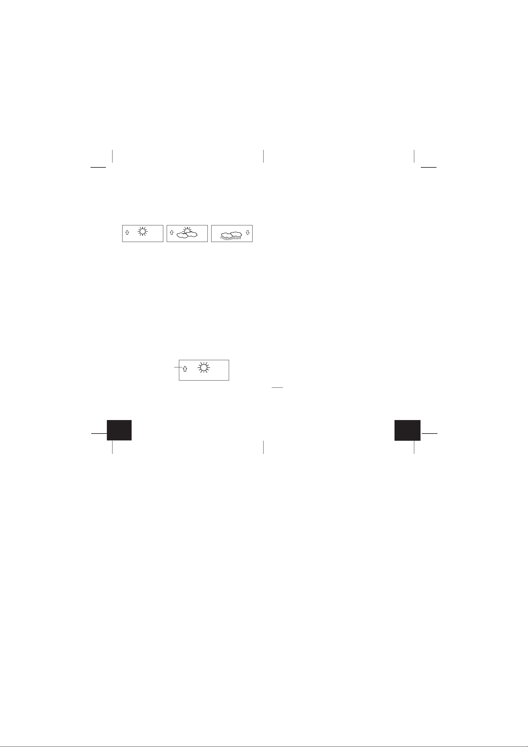
1. Weather Icons
a. There are 3 possible weather icons that will be displayed at v arious
times in the center of the indoor weather station.
i Sunny-indicates that the weather is expected to improve (not
that the weather will be sunny).
ii Sun with Clouds-indicates that the weather is expected to be
fair (not that the weather will be sunny with clouds).
iii Clouds with Rain-indicates that the weather is expected to get
worse (not that the weather will be rainy).
b. The weather icons change when the unit detects a change in air
pressure.
c. The icons change in order, from “sunny” to “sun with clouds” to
“clouds with rain” or the reverse.
d. It will not change from “sunny” directly to “clouds with rain”, although
it is possible for the change to occur quickly.
e. If the symbols do not change, the weather has not changed (or the
change has been slow and gradual).
f. The sensitivity of the change in foreacst icon is set by the user in
section F of the Detailed Set Up Guide.
E. Weather Tendency Arrows
1. Along with the forecast icon there is a pressure tendency arrow.
2. There is one that points up (on the left side of the LCD) and one
that points down (on the right side of the LCD).
Pressure trend arrow
7. A storm can be expected if there is a drop of 4 hPa or more in less
than 6 hours. The clouds with rain icon will be displayed and the
tendency arrow that points down will be flashing-indicating the storm
warning feature has been activated. The flashing will stop when
the air pressure stabilizes or begins to rise.
F. Barometric Air Pressure Reading
1. The actual barometric air pressure is displayed directly under the
weather forecast icon
2. The relative air pressure is calibrated by the user through the programming mode.
3. Please Follow the programming instructions in section F of the Detailed Set Up Guide to set this feature.
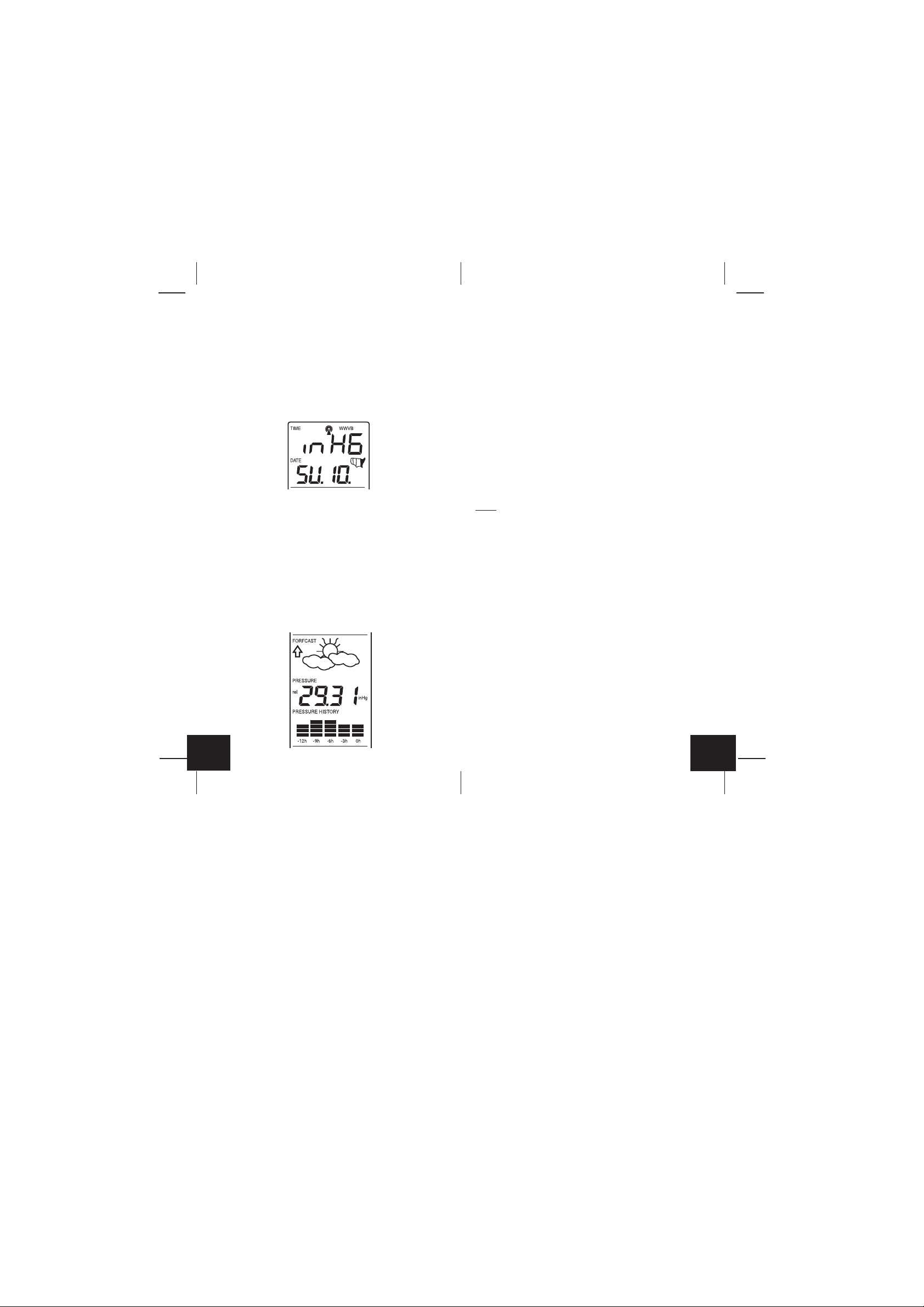
G. Air Pressure History Bar Chart
1. The bar graph shows in hPa (Hekto Pascal) the recorded air pressure over the past 12-hours.
2. The horizontal axis shows the hours at increments of -12 hours, -9
hours, -6 hours, -3 hours, and 0 hours (current).
3. The vertical axis is set by hPa: the “0” on this axis represents the
current hPa, and + or - 1,3,5, or 7 shows (in hPa) how high or low
the past air pressure was as compared to the current one.
4. The “0” on the v ertical axis indicates the current air pressure value.
5. The “0h” on the horizontal axis indicates the current hour, thus the
current air pressure also.
6. Each bar on the bar graph represents a value of 0.03 hPa, and
each bar also has a corresponding value on the verticle axis.
7. Air pressure trends can be determined by simply glancing at the
bar graph.
a. If the bars are rising (higher on the right than the left) then the
air pressure has a rising trend, and the weather should improve.
b. If the bars are dropping (lower on the right than the left) then the
air pressure has a falling trend, and the weather should worsen.
8. Multiply the two values to find past air pressure (note the + or - sign
of values on the verticle axis); i.e. 0.03 hPa x 3 = 0.09 hPa, now
add this value to the air pressure (in LCD 4) to evaluate what past
air pressures have been.
9. The bar chart will constantly scroll to avoid burnout of the LCD.
3. These arrows reflect current changes in the air pressure.
4. An arrow pointing up indicates that the air pressure is increasing
and the weather is expected to improve or remain good.
5. An arrow pointing down indicates that the air pressure is decreasing and the weather is expected to become worse or remain poor.
6. No arrow means the pressure is stable.
GB
P.17
Note:
This feature cannot be turned off.
P.18
GB

VII.
MOUNTING
Note:
Before permanently mounting, ensure that the indoor weather
station is able to receive signals from the transmitters and WWVB signal at the desired location. To achieve a tr ue temperature reading,
avoid mounting the remote temperature sensor (or any sensor) where
direct sunlight can reach the remote sensor. We recommend that you
mount the remote sensor on a North-facing wall or under an eve. The
sending range of the remote temperature sensor is 330-ft (100m) however obstacles such as walls, concrete, and large metal objects can
reduce the range. Place all units in their desired location, and wait
approximately 15 minutes before permanently mounting to ensure that
there is proper reception. If the indoor weather station loses the signal
from the remote sensor, it will display the last temperature reading for
15 minutes. After 15 minutes of not receiving any signals, the remote
temperature will display “- -.-”.
A. Mounting the Remote Temperature Sensor
The remote temperature sensor can be mounted in two ways:
• with the use of screws
• using the adhesive tape
1. MOUNTING WITH SCREWS
a. Remove the mounting bracket from the remote temper ature sensor .
b. Place the mounting bracket over the desired location.
c. Through the three screw holes of the bracket, mark the mounting
surface with a pencil.
d. Screw mounting bracket onto the mounting surface. Ensure that
the screws are flush with the bracket.
e. Insert the remote temperature sensor into the bracket.
2. MOUNTING WITH ADHESIVE TAPE
a. With a nonabrasive solution, clean and dry the back of the mount-
ing bracket and the mounting surface to ensure a secure hold. The
mounting surface should be smooth and flat.
b. Remove the protective strip from one side of the tape.
c. Adhere the tape to the designated area on the back of the mount-
ing bracket.
d. Remove the protective strip from the other side of the tape.
e. Position the remote temperature sensor in the desired location, en-
suring that the indoor weather station can receive the signal.
B. Mounting the WS-7394U Indoor Weather Station
The indoor weather station can be mounted in two ways:
• with the table stand
• on the wall with the use of a wall hanging screw (not included)
1. USING THE TABLE STAND
The indoor weather station comes with the table stand already mounted.
If you wish to use the table-stand all that is required is to place the
indoor weather station in an appropriate location.
2. WALL MOUNTING
a. Remove the table-stand. To do this, pull down on the stand from
the rear and rotate forward.
b. Fix a screw (not included) into the desired wall, leaving approxi-
mately 3/16 of an inch (5mm) extended from the wall.
c. Place the indoor weather station onto the screw using the hanging
hole on the backside.
d. Gently pull the indoor weather station down to lock the screw into
place.
MAINTENANCE AND CARE INSTRUCTIONS
A. Extreme temperatures, vibration, and shock should be avoided to
prevent damage to the units.
B. Clean displays and units with a soft, damp cloth. Do not use sol-
vents or scouring agents; they may mark the displays and casings.
C. Do not submerge in water.
D. Immediately remove all low powered batteries to av oid leakage and
damage.
E. Opening the casings invalidates the warranty. Do not try to repair
the unit. Contact La Crosse Technology for repairs.
TROUBLESHOOTING
Problem: The LCD is faint.
Solution:
1) Set the LCD contrast to a higher level.
2) Replace batteries.
Problem: No outdoor temperature/humidity is displayed.
Solution:
1) Remove all batteries, reinsert into the remote temperature sensor
first, then into the indoor weather station.
2) Place remote temperature sensor closer to the indoor weather
station.
3) Be sure all batteries are fresh.
4) No other interfering sources are being used (such as computer
monitors, TV sets, headphones, or speakers) in the vicinity. The
signal travels in a straight line, an electrical source near that “line”
may cause interference.
GB
P.19
P.20
GB

Problem: Temperature, humidity, or air pressure is incorrect.
Solution:
1) Check/Replace batteries.
2) If multiple remote sensors are in use, check location with corresponding “boxed numbers.”
3) Move away from sources of heat/cold.
4) Adjust relative air pressure to a value from a reliable source (TV
radio, etc.).
5) The indoor weather station and remote sensors are calibrated at
the factory. If there is a consistent problem, please call La Crosse
Technology.
Problem: “- -” in humidity display.
Solution:
1) Humidity is below 1% or above 99%.
2) TX3U or TX3UP is used for remote temperature.
Problem: WWVB time and date will not set or update
Solution:
1) Wait until overnight for signal to be received
2) Move indoor weather station away from sources of electricity
3) Place indoor weather station in window facing Colorado
4) The first reception is most difficult, as the indoor weather station
needs five continual minutes of clear signal reception. After the
initial time/date set, the indoor weather station only requires one
full minute of clear reception each night.
SPECIFICATIONS
Indoor weather station recommended
operating temperature 32˚F to 122˚F (0˚C to 50˚C)
LCD contrast 8 levels (0-7)
Temperature measuring range
Indoor 14.2˚F to 139.8˚F with 0.2˚F resolution
(-9.9˚C to 59.9˚C with 0.1˚C resolution)
(“OFL” displayed if outside this range)
Outdoor -21.8˚F to 157.8˚F with 0.2˚F resolution
(-29.9˚C to 69.9˚C with 0.1˚C resolution)
(“OFL” displayed if outside this range)
Relative humidity range
Indoor 1% to 99% with 1% resolution,
indoor weather station displays “—.-”
if outside this range
Air pressure
Relative hPa (adjustable) 960 hPa to 1040 hPa
Relative inHg (adjustable) 28.35 inHg to 30.72 inHg
Sensitivity setting hPa 2 hPa to 4 hPa
Air pressure history For the past 12 hours
(0, -3, -6, -9, and -12 hours)
Data checking intervals
Indoor temperature Every 15 second
Indoor humidity Every 20 seconds
Outdoor temperature Every 5 minutes
Transmitter reading update (within sensor)
Outdoor temperature Every 1 minute
Transmission frequency 433.92 MHz
Transmission range 330 feet (100m)
Power supply
Indoor weather station: 2 x AA, IEC LR6, 1.5V batteries.
Remote temperature sensor: 2 x AA, IEC LR6, 1.5V batteries.
Dimensions (H x W x D)
Indoor weather station 8.75" x 4" x 1.5"
(222 x 102 x 38 mm)
Remote temperature sensor 5.04" x 1.57" x 0.9"
(128 x 40 x 23 mm)
WARRANTY INFORMATION
La Crosse Technology, Ltd provides a 1-year limited warranty on this
product against manufacturing defects in materials and workmanship.
This limited warranty begins on the original date of purchase, is valid
only on products purchased and used in North America and only to
the original purchaser of this product. To receive warranty service, the
purchaser must contact La Crosse Technology, Ltd for problem determination and service procedures. Warranty service can only be performed by a La Crosse T echnology, Ltd authorized service center. The
original dated bill of sale must be presented upon request as proof of
purchase to La Crosse Technology, Ltd or La Crosse Technology, Ltd’s
authorized service center.
La Crosse Technology, Ltd will repair or replace this product, at our
option and at no charge as stipulated herein, with new or reconditioned parts or products if found to be defective during the limited warranty period specified above. All replaced parts and products become
the property of La Crosse Technology, Ltd and must be returned to La
Crosse Technology, Ltd. Replacement parts and products assume
the remaining original warranty , or ninety (90) da ys, whiche ver is longer .
La Crosse Technology, Ltd will pay all expenses for labor and materi-
GB
P.21
P.22
GB

als for all repairs covered by this warranty. If necessary repairs are
not covered by this warranty, or if a product is examined which is not in
need or repair, you will be charged f or the repairs or e xamination. The
owner must pay any shipping charges incurred in getting y our La Crosse
Technology, Ltd product to a La Crosse Technology, Ltd authorized
service center. La Crosse Technology, Ltd will pay reasonable return
shipping charges to the owner of the product.
Your La Crosse Technology, Ltd warranty covers all defects in material
and workmanship with the following specified exceptions: (1) damage
caused by accident, unreasonable use or neglect (including the lack of
reasonable and necessary maintenance); (2) damage occurring during shipment (claims must be presented to the carrier); (3) damage to ,
or deterioration of, any accessory or decorative surface; (4) damage
resulting from failure to follow instructions contained in your owner’s
manual; (5) damage resulting from the perf ormance of repairs or alterations by someone other than an authorized La Crosse Technology,
Ltd authorized service center; (6) units used for other than home use
(7) applications and uses that this product was not intended or (8) the
products inability to receive a signal due to any source of interference ..
This warranty covers only actual defects within the product itself, and
does not cover the cost of installation or removal from a fix ed installation,
normal set-up or adjustments, claims based on misrepresentation by
the seller or performance variations resulting from installation-related
circumstances.
LA CROSSE TECHNOLOGY, LTD WILL NOT ASSUME LIABILITY
FOR INCIDENT AL, CONSEQ UENTIAL, PUNITIVE, OR O THER SIMILAR DAMAGES ASSOCIATED WITH THE OPERATION OR MALFUNCTION OF THIS PRODUCT. THIS PRODUCT IS NOT TO BE
USED FOR MEDICAL PURPOSES OR FOR PUBLIC INFORMA TION.
THIS PRODUCT IS NOT A TOY. KEEP OUT OF CHILDREN’S
REACH.
This warranty gives you specific legal rights. You may also have other
rights specific to your State. Some States do no allo w the e xclusion of
consequential or incidental damages therefore the above e xclusion of
limitation may not apply to you.
For warranty work, technical support, or information contact:
La Crosse Technology, Ltd
190 Main Street
La Crescent, MN 55947
Phone: 507.895.7095
Fax: 507.895.2820
e-mail:
support@lacrossetechnology.com
(warranty work)
sales@lacrossetechnology.com
(information on other products)
web:
www.lacrossetechnology.com
Questions ? Please see instruction video at
www.lacrossetechnology.info/7394
All rights reserved. This handbook must not be reproduced in any
form, even in excerpts, or duplicated or processed using electronic,
mechanical or chemical procedures without written permission of the
publisher.
This handbook may contain mistakes and printing errors. The information in this handbook is regularly checked and corrections made in
the next issue. We accept no liability for technical mistakes or printing
errors, or their consequences.
All trademarks and patents are acknowledged.
GB
P.23
P.24
GB

TABLE DES MATIÈRES
Sujet Page
Inventaire/ Équipement supplémentaire 26
A propos du WWVB 26
Guide de paramétrage rapide 27
Guide de paramétrage détaillé
Installation des Piles 2 8
Séquence de mise en route 29
Explication des informations affichées à l’écran LCD 31
Disposition des touches de fonction 32
Mode Programmation
Récapitulatif de la séquence de programmation 3 2
Contraste de l’écran LCD 32
Fuseau horaire 33
Heure d’été 33
Activation/désactivation de l’heure radiocommandée 34
Format 12/24 H 3 4
Réglage manuel de l’heure/date 35
Unités de mesure de la température (˚C/˚F) 36
Unités de mesure de la pression atmosphérique (inHg/hPa)
Pression atmosphérique relative 37
Sensibilité des prévisions météo 38
Fonctionnalités et fonctionnement
Relevés minimum/maximum de température/humidité 3 9
Capteurs de température/humidité distants multiples 40
Icône du confort 41
Prévisions météo et indicateurs de tendance météo 41
Icônes météo 41
Flèches de tendance météo 42
Relevé de la pression atmosphérique barométrique 42
Historique de la pression atmosphérique 42
Fixation 43
Entretien et soin 44
Dépistage des pannes 45
Caractéristiques techniques 46
Informations sur la garantie 47
37
INVENTAIRE
1. La station météo WS-7394U
2. Le capteur de température (température/humidité)) distant TX6U
3. Manuel d’instructions et fiche de garantie
ÉQUIPEMENT SUPPLÉMENTAIRE (non-fourni)
1. Cinq piles neuves 1,5V de type AA.
2. Une vis de fixation murale (en option)
APROPOS DE L’ÉMETTEUR WWVB (Heure radiocommandée)
L’émetteur radio WWVB de la NIST (National Institute of Standards
and Technology-Time and Frequency Division) WWVB est situé à Ft.
Collins dans le Colorado et émet un signal horaire exact en continu
sur 60 kHz à travers les États-Unis. Le signal peut être réceptionné
dans un rayon de 3 200 km à l’aide de l’antenne incorporée à la station météo. Cependant, cette réception est très restreinte pendant la
journée, à cause des effets de l’ionosphère terrienne. Chaque nuit,
lorsque les conditions de réception sont optimales, la station météo
recherchera le signal. L’émetteur radio WWVB prend son signal à partir
de l’horloge atomique de la NIST à Boulder, Colorado. Une équipe de
physiciens en atomique mesure en continu chaque seconde de chaque
jour à une précision de dix-milliardièmes de seconde par jour. Ces
physiciens ont établi la norme internationale pour une seconde, comme
F
P.25
P.26
F

étant 9 192 631 770 vibrations d’un atome de Césium-133 dans un
vacuum. Pour plus d’informations sur le WWVB et l’horloge atomique,
visitez le site web du NIST
tions/wwvb.htm
http: //www.boulder.nist.gov/timefreq/sta-
GUIDE DE PARAMÉTRAGE RAPIDE
Conseil :
rechargeables.
1. Placez le capteur de température distant à 1m - 1m 50 de la station
2. Les piles doivent être retirées des deux unités pendant 15 minutes.
3. Insérez en premier les piles du capteur de température distant,
4. N’APPUYEZ SUR AUCUNE TOUCHE PENDANT 15 MINUTES.
Pendant ce temps, la station météo intérieure et le capteur de
température commenceront à ‘dialoguer’, la station affichant la
température et l’humidité intérieures et la température extérieure. Si la
station météo n’affiche pas toutes ces informations dans les 15 minutes,
répétez la procédure de paramétrage détaillée ci-dessus. Lorsque les
informations ont été affichées pendant 15 minutes, vous pouvez installer vos capteurs à l’extérieur et régler l’heure.
Le capteur de température distant doit être placé dans un endroit sec
et ombragé. Le rayon d’émission du capteur de température distant
est de 100 mètres. Tout mur se trouvant sur la trajectoire du signal
réduira sa portée. Un mur extérieur ou une fenêtre peut réduire la
portée de 6 à 9 mètres, un mur intérieur de 3 à 6 mètres. La distance,
en tenant compte des réductions, ne doit pas excéder 100 mètres en
ligne droite.
Utilisez des piles alcalines de marque et évitez les piles
météo intérieure.
puis celles de la station météo intérieure.
(Tous les capteurs de température distants doivent être initialisés
avant la station météo intérieure)
vérifiez que les unités sont dans le rayon de réception l’un de l’autre
ou répétez l’installation des piles.
GUIDE DE PARAMÉTRAGE DETAILLE
I. Installation des piles
Les piles s’enclenchent fermement. Afin d’éviter tout problème au
démarrage, vérifiez qu’elles restent bien en place. Aussi, prenez soin
d’installer les piles du capteur de température en premier, puis celles
de la station météo. La mise en route initiale doit être eff ectuée a v ec la
station météo intérieure et le capteur de température dans la même
pièce. Les unités ne doivent être fixées en place que lorsque la
réception du signal a été vérifiée.
A. Capteur de température et d’humidité distant
1. Retirez le support de fixation. Le support se détache et s’attache
facilement.
2. Retirez le couvercle du compartiment à piles en le faisant glisser
vers le bas.
3. Installez 2 piles de type AA en respectant la polarité. Les piles
s’enclenchent fermement (afin d’éviter tout problème au démarrage,
vérifiez qu’elles restent bien en place).
4. Remplacez le couvercle du compartiment en le faisant glisser vers
le haut. Assurez-vous de sa bonne fermeture.
le couvercle du
compartime
REMARQUE :
sur le capteur de température distant mais la pluie doit être évitée.
Pour terminer l’installation de votre station météo intérieure une fois
les 15 minutes écoulées, référez-vous au Guide de paramétrage
détaillé.
Note:
minutes ; après installation des piles, la station météo intérieure
recherchera un signal pendant 5 minutes. Si, après 5 minutes, aucune
température n’est affichée à la section EXTÉRIEUR de l’écran LCD,
F
Le brouillard et la brume n’auront aucun effet nuisible
Le capteur de température distant émet un signal toutes les 3
P.27
P.28
F

B. Station météo intérieure
1. Retirez le couvercle du compartiment à piles (le couvercle porte un
texte en blanc).
2. Insérez deux piles alcalines de type AA en respectant la polarité.
3. N’appuyez sur aucune touche pendant dix minutes minimum. Si
une touche est pressée avant que la station ne reçoive les inf ormations du capteur TX6U, aucune donnée ne ser a reçue de ce capteur
jusqu’à ce que celui-ci soit réinitialisé.
4. Remettez le couvercle du compartiment à piles.
II. Séquence de mise en route
A. Mise en route initiale
1. Immédiatement après l’installation des piles, l’écran LCD s’allume
momentanément en entier.
2. Toutes les informations s’affichent alors en mode normal, l’heure
par défaut étant “12:00” et la date par défaut “WE.1” (l’année est
2004).
3. La température et l’humidité intérieures et la pression atmosphérique
barométrique (29,91 inHg HR) seront également affichées.
4. Une icône “satellite” s’affiche en bas de l’écran LCD à gauche de la
température extérieure pour indiquer que la station météo intérieure
recherche le signal provenant du capteur de température distant.
La température distante devrait s’afficher dans les cinq minutesdans le cas contraire, retirez toutes les piles des unités, puis répétez
la procédure d’installation en commençant par le capteur de
température distant, suivi de la station météo intérieure.
B. Réception du signal WWVB
1. Lorsque les piles sont installées dans la station météo intérieure,
celle-ci commence automatiquement à rechercher le signal WWVB.
Si un bon signal est reçu (peu probable le jour dans la plupart des
localités), l’indicateur de réception WWVB (en forme de tour)
clignote. Il faut cinq bonnes minutes de réception d’un signal
suffisamment fort, pour permettre à la station météo intérieure de
régler l’heure, les minutes, les secondes, le mois, la date et l’année .
Si la réception n’est pas complétée dans les dix minutes, la recherche sera annulée et retentée automatiquement toutes les deux
heures jusqu’à réception définitive du signal.
2. Le signal est émis uniquement depuis Ft. Collins, Colorado et
ressemble à un signal radio AM. Les perturbations atmosphériques
telles qu’orages, taches solaires et même le ray onnement du soleil
peuvent entraver le signal.
3. Pour maximiser les chances de réception, placez la station météo
intérieure à une fenêtre, orientée en direction du Colorado et à
deux mètres minimum de tout appareil électrique (ordinateurs,
téléviseurs, réfrigérateurs, etc.). Ne déplacez pas la station météo
intérieure pendant la recherche du signal.
4. L’heure et la date peuvent être réglées manuellement. Lorsque le
signal est reçu, l’heure et la date réglées manuellement seront
remplacées en fonction du fuseau horaire.
5. Lorsque l’heure et la date sont réglées, la station météo intérieure
recherchera le signal toutes les nuits à minuit afin de maintenir sa
précision (l’heure d’été est appliquée automatiquement). Si le signal a été reçu au cours des 24 dernières heures, l’indicateur de
réception s’affiche.
F
P.29
P.30
F

III. Explication des informations affichées à l’écran LCD
A. Le schéma ci-dessous présente les fonctionnalités de l’écran LCD.
Indicateur de
réception WWVB
Affichage de la
date
Affichage de la
température et de
l’humidité
intérieures
Indicateur de
tendance de la
pression
atmosphérique
Pression
atmosphérique
Histogramme de la
pression
atmosphérique sur
les 12 dernières
heures
Heure
radiocommandé
Icône du confort
Icône de prévision
IV.Disposition des touches de fonction
A. Le schéma ci-dessous présente les quatre touches de fonction
utilisées pour la programmation et le fonctionnement de votre station météo intérieure
V. Mode Programmation
Le mode programmation est disposé de manière à permettre une
programmation individuelle de chaque fonction ou une programmation
globale de la station météo intérieure. La programmation globale
s’effectue normalement à l’installation initiale et, dans ce cas, les étapes
1,2 et 3 de chaque rubrique de programmation ne sont pas prises en
compte. Vous pouvez quitter le mode programmation à tout moment
en appuyant sur la touche “CH” ou en attendant la temporisation de 15
secondes.
A. Récapitulatif de la séquence de programmation
1. Contraste LCD 2. Fuseau horaire 3. Heure d’été
4.
Activation/désactivation
5. Format 12/24 H 6. Heure
de l’heure radiocommandée
7. Minutes 8. Année 9. Mois
10.Date 11.˚F/˚C 12.inHg/hPa
13.Pression atmosphérique 14.Sensibilité des
relative prévisions météo
B. Contraste de l’écran LCD
Affichage de la
température
extérieure
Identifiant du
capteur distant (3
maximum)
B. La station météo intérieure fonctionne en plusieurs modes. L’écran
LCD est présenté ici en mode normal ; les données affichées sur
votre station météo seront différentes selon vos paramètres et les
conditions locales.
F
P.31
1. Appuyez sur la touche “SET” pendant cinq secondes.
2. “lcd” s’affiche en haut de l’écran, accompagné d’un chiffre clignotant.
3. Appuyez sur la touche “OUT/+” pour sélectionner le niveau de
contraste désiré.
P.32
F

4. Appuyez sur la touche “SET” pour confirmer le niveau du contraste
et passer en mode réglage du fuseau horaire.
C. Fuseau horaire
1. Appuyez sur la touche “SET” pendant cinq secondes.
2. “lcd” s’affiche en haut de l’écran, accompagné d’un chiffre clignotant.
3. Appuyez de nouveau sur la touche “SET” pour avancer à la
programmation du fuseau horaire.
4. Un chiffre clignote à gauche de la lettre “h” en haut de l’écran, sous
l’affichage de l’heure.
5. Appuyez sur la touche “OUT+” pour sélectionner le fuseau horaire .
6. Appuyez sur la touche “SET” pour confirmer le fuseau horaire et
passer à la programmation de l’heure d’été.
E. Activation (ON)/désactivation (OFF) de l’heure
radiocommandée
1. Appuyez sur la touche “SET” pendant cinq secondes.
2. “lcd” s’affiche en haut de l’écran, accompagné d’un chiffre clignotant.
3. Appuyez encore trois fois sur la touche “SET” pour avancer à
l’activation/désactivation de l’heure radiocommandée.
4. “RCC” s’affiche au-dessus de l’affichage de la température/humidité
intérieure et “ON” ou “OFF” clignote juste au-dessus.
5. Appuyez sur la touche “OUT/+” pour activer (ON) ou désactiver
(OFF) l’heure radiocommandée.
6. Appuyez sur la touche “SET” pour confir mer l’activation ou la
désactivation de l’heure radiocommandée et passer en mode
programmation du format 12/24 H.
D. Heure d’été
1. Appuyez sur la touche “SET” pendant cinq secondes.
2. “lcd” s’affiche en haut de l’écran, accompagné d’un chiffre clignotant.
3. Appuyez encore deux fois sur la touche “SET” pour avancer à la
programmation de l’heure d’été.
4. “DST” s’affiche au-dessus de l’affichage de la température/humidité
intérieure et “ON” ou “OFF” clignote juste au-dessus.
5. Appuyez sur la touche “OUT/+” pour activer (ON) ou désactiver
(OFF) l’heure d’été.
Remarque :
n’appliquent pas l’heure d’été.
6. Appuyez sur la touche “SET” pour confir mer l’activation ou la
F
Certaines régions (dont l’Arizona et une partie de l’Indiana)
désactivation de l’heure d’été et passer en mode activation/
désactivation de l’heure radiocommandée.
P.33
F. Format 12/24 H
1. Appuyez sur la touche “SET” pendant cinq secondes.
2. “lcd” s’affiche en haut de l’écran, accompagné d’un chiffre clignotant.
3. Appuyez encore quatre fois sur la touche “SET” pour avancer à la
programmation du format 12/24 H.
4. “12h” ou “24h” clignote au-dessus de l’affichage de la température/
humidité intérieure.
5. Appuyez sur la touche “OUT/+” pour sélectionner soit le format 12
H, soit le format 24 H.
Remarque :
gauche de l’heure. En dehors de ces heures, rien n’est affiché. Prenez
soin de sélectionner l’heure correspondante, AM ou PM, afin d’assurer
la réception automatique.
En format 12H et entre midi et minuit, “PM” s’affiche à
P.34
F

6. Appuyez sur la touche “SET” pour confirmer le f ormat 12H ou 24H
et passer en mode réglage manuel de l’heure.
G. Réglage manuel de l’heure
Le signal WWVB remplace tous les réglages manuels de l’heure et de
la date. L’heure sera en fonction du fuseau horaire sélectionné.
1. Appuyez sur la touche “SET” pendant cinq secondes.
2. “lcd” s’affiche en haut de l’écran, accompagné d’un chiffre clignotant.
3. Appuyez encore cinq fois sur la touche “SET” pour avancer au
réglage manuel de l’heure.
4. Le chiffre des heures clignote en haut de l’écran.
5. Appuyez sur la touche “OUT/+” pour régler l’heure.
6. Appuyez sur la touche “SET” pour confirmer l’heure et passer au
réglage des minutes.
H. Réglage manuel des minutes
1. Appuyez sur la touche “SET” pendant cinq secondes.
2. “lcd” s’affiche en haut de l’écran, accompagné d’un chiffre clignotant.
3. Appuyez encore six fois sur la touche “SET” pour av ancer au réglage
manuel des minutes.
4. Le chiffre des minutes clignote en haut de l’écran.
5. Appuyez sur la touche “OUT/+” pour régler les minutes.
6. Appuyez sur la touche “SET” pour confirmer les minutes et passer
au réglage de l’année.
I. Réglage manuel de l’année
1. Appuyez sur la touche “SET” pendant cinq secondes.
2. “lcd” s’affiche en haut de l’écran, accompagné d’un chiffre clignotant.
3. Appuyez encore sept fois sur la touche “SET” pour avancer au
réglage manuel de l’année.
4. L’année clignote en dessous de l’affichage de l’heure.
5. Appuyez sur la touche “OUT/+” pour sélectionner l’année.
6. Appuyez sur la touche “SET” pour confirmer l’année et passer au
réglage du mois.
J. Réglage manuel du mois
1. Appuyez sur la touche “SET” pendant cinq secondes.
2. “lcd” s’affiche en haut de l’écran, accompagné d’un chiffre clignotant.
3. Appuyez encore huit fois sur la touche “SET” pour avancer au
réglage manuel du mois.
4. Le mois clignote en dessous de l’affichage de l’heure.
5. Appuyez sur la touche “OUT/+” pour sélectionner le mois.
6. Appuyez sur la touche “SET” pour confirmer le mois et passer au
réglage de la date.
K. Réglage manuel de la date
1. Appuyez sur la touche “SET” pendant cinq secondes.
2. “lcd” s’affiche en haut de l’écran, accompagné d’un chiffre clignotant.
3. Appuyez encore neuf fois sur la touche “SET” pour avancer au
réglage manuel de la date.
4. La date clignote en dessous de l’affichage de l’heure.
5. Appuyez sur la touche “OUT/+” pour sélectionner la date.
6. Appuyez sur la touche “SET” pour confirmer la date et passer à la
programmation des unités de température.
L. Unités de mesure de la température (˚F ou ˚C)
1. Appuyez sur la touche “SET” pendant cinq secondes.
2. “lcd” s’affiche en haut de l’écr an, accompagné d’un chiffre clignotant.
F
P.35
P.36
F

3. Appuyez encore dix fois sur la touche “SET” pour avancer à la
programmation des unités de mesure de la température.
4. ˚F ou ˚C clignote en haut de l’écran.
5. Appuyez sur la touche “OUT/+” pour sélectionner les unités de
mesure de la température.
6. Appuyez sur la touche “SET” pour confirmer les unités de mesure
de la température et passer à la programmation des unités de
mesure de la pression atmosphérique.
M. Unités de mesure de la pression atmosphérique (inHg/hPa)
1. Appuyez sur la touche “SET” pendant cinq secondes.
2. “lcd” s’affiche en haut de l’écran, accompagné d’un chiffre clignotant.
3. Appuyez encore onze fois sur la touche “SET” pour avancer à la
programmation des unités de mesure de la pression atmosphérique.
4. inHg ou hPa clignote en haut de l’écran.
5. Appuyez sur la touche “OUT/+” pour sélectionner les unités de
mesure de la pression atmosphérique.
6. Appuyez sur la touche “SET” pour confirmer les unités de mesure
de la pression atmosphérique et passer à la programmation de la
pression relative.
N. Pression atmosphérique relative
3. Appuyez encore onze fois sur la touche “SET” pour avancer à la
programmation de la pression relative.
4. La pression atmosphérique barométrique clignote au centre de
l’écran juste en dessous de l’icône de prévision météo
5. Appuyez sur la touche “OUT/+” ou “IN” pour sélectionner l’unité de
mesure de la pression atmosphérique.
6. Appuyez sur la touche “SET” pour confirmer la pression relative et
passer à la programmation de la sensibilité des prévisions météo.
O. Sensibilité des prévisions météo
1. Appuyez sur la touche “SET” pendant cinq secondes.
2. “lcd” s’affiche en haut de l’écran, accompagné d’un chiffre clignotant.
3. Appuyez encore treize fois sur la touche “SET” pour avancer à la
programmation de la sensibilité des prévisions météo.
4. Les deux flèches de tendance de la pression atmosphérique
clignotent de part et d’autre de l’icône de prévision et un chiffre
clignotant s’affiche sous l’icône.
5. Appuyez sur la touche “OUT/+” pour sélectionner le niveau de
sensibilité des prévisions météo.
1. Appuyez sur la touche “SET” pendant cinq secondes.
2. “lcd” s’affiche en haut de l’écran, accompagné d’un chiffre clignotant.
F
P.37
Remarque :
présentée en tant que “pression atmosphérique relative “. Ce relevé
est basé sur une combinaison de la pression atmosphérique absolue
et l’altitude. En général, la pression atmosphérique diminue avec
l’altitude. Le rele vé de pression atmosphérique relative prend en compte
la pression atmosphérique dans des localités avoisinantes afin de
permettre une prévision conforme. Seul le relevé de pression
atmosphérique relative peut être étalonné, et non celui de la pression
atmosphérique absolue de la station météo.
6. Appuyez sur la touche “SET” pour confirmer le niv eau de sensibilité
LA PROGRAMMA TION MANUELLE EST MAINTENANT TERMINÉE
La pression atmosphérique barométrique est souvent
des prévisions météo.
P.38
F

FONCTIONNALITÉS ET FONCTIONNEMENT
A. Relevés minimum et maximum de température et d’humidité
1. Température et humidité minimum et maximum intérieures
La station météo intérieure mémorise automatiquement les relevés
minimum et maximum de température et d’humidité intérieures. Les
valeurs minimums et maximums sont automatiquement mises à jour
lorsqu’un nouveau minimum ou maximum est relevé ou en cas de
réinitialisation manuelle.
a. En mode d’affichage normal, appuyez une fois sur la touche
“IN” pour afficher les relevés maximums de température et
d’humidité intérieures (“MAX” s’affiche au-dessus de la
température et humidité intérieures).
b. Appuyez de nouveau sur la touche “IN” pour afficher les relevés
minimums de température et d’humidité intérieures.
c. Appuyez de nouveau sur la touche “IN” pour revenir en mode
normal (lors de l’affichage des relevés minimum/maximum, une
temporisation intervient au bout de quinze secondes d’inactivité).
Remarque:
température et d’humidité intérieures, affichez en premier les valeurs
à réinitialiser (minimum ou maximum). Appuy ez ensuite sur la touche
“SET” pendant trois secondes minimum. Les relevés seront alors
réinitialisés aux valeurs de température et d’humidité et l’heure
actuelles.
2. Température minimum et maximum extérieure
La station météo intérieure mémorise automatiquement les relevés
minimum et maximum de température extérieure. Les valeurs minimums et maximums sont automatiquement mises à jour lorsqu’un
nouveau minimum ou maximum est relevé ou en cas de réinitialisation
manuelle.
Pour réinitialiser les relevés maximum et minimum de
a. En mode d’affichage normal, appuyez une fois sur la touche
“OUT/+” pour afficher le relevé maximum de température
extérieure (“MAX” s’affiche au-dessus de la température
extérieure).
b. Appuyez de nouveau sur la touche “OUT/+” pour afficher le relevé
minimum de température extérieure.
c. Appuyez de nouveau sur la touche “OUT/+” pour rev enir en mode
normal (lors de l’affichage des relevés minimum/maximum, une
temporisation intervient au bout de quinze secondes d’inactivité).
Remarque:
température extérieure, affichez en premier les valeurs à réinitialiser
(minimum ou maximum). Appuyez ensuite sur la touche “SET” pendant trois secondes minimum. Les relevés seront alors réinitialisés
aux valeurs de température et l’heure actuelles.
B. Capteurs de température distants multiples
La station WS-7394U peut réceptionner les signaux provenant de 3
capteurs distants différents. Ces capteurs distants supplémentaires
sont disponibles chez le revendeur de cet appareil. Le modèle TX4U
contrôle la température et l’humidité ; le modèle TX3U contrôle la
température et l’affiche à son écran LCD ; le modèle TX3UP contrôle
la température via une sonde pour la mesure de la température de la
terre ou de l’eau ; le modèle TX6U contrôle uniquement la température .
Remarque :
tant d’insérer en premier les piles de tous les capteurs distants et par
ordre numérique. Installez ensuite les piles dans la station météo
intérieure. Des problèmes de transmission se produiront si cette
séquence n’est pas respectée et si le temps d’installation totale dépasse
6 minutes
1. Installation de capteurs multiples
a. Il est nécessaire d’enlever les piles de toutes les unités actuellement
b. Retirez les couvercles des compartiments à piles de tous les
c. Placez tous les capteurs par ordre numérique.
d. Installez les piles dans les capteurs distants dans l’ordre numérique
e. Installez les piles de la station météo intérieure.
f. Référez-vous au Guide de Paramétrage Détaillé pour les instruc-
2. Capteurs distants multiples - affichage et fonctionnement
a. Pour afficher le relevé de tempér ature d’un capteur distant différent,
b. Les relevés minimum et maximum du capteur distant additionnel
c. Pour réinitialiser les relevés minimum et maximum de température,
Pour réinitialiser les relevés maximum et minimum de
Lors de l’installation de capteurs multiples, il est impor-
en fonctionnement.
capteurs distants.
en suivant les instructions d’installation détaillées à la rubrique Guide
de Paramétrage Détaillé de ce manuel.
tions de programmation et de fonctionnement.
appuyez sur la touche “CH”. Le chiffre encadré affiché à la section
EXTÉRIEUR l’écran LCD devrait changer.
peuvent être affichés en appuyant sur la touche “OUT/+”.
appuyez sur la touche “SET” pendant 3 secondes ; seul le relevé
concerné de ce capteur sera réinitialisé.
F
P.39
P.40
F

Les relevés minimum et maximum de chaque capteur distant sont
stockés en mémoire.
C. Indicateur du confort intérieur
1. L’indicateur du confort intérieur est affiché entre la température et
l’humidité intérieures.
2. L’indicateur affiche une émoticône souriante lorsque la température
se situe entre 20˚C et 25,9˚C (68˚F et 79˚F),et l’humidité entre 45%
et 64%.
3. Une émoticône grimaçante est affiché lorsque la température et
l’humidité se situent en dehors de ces plages.
D. Prévisions météo et indicateurs de tendance météo
La précision de la fonctionnalité de prévision météo, basée uniquement
sur les variations de pression atmosphérique sur une durée, est
estimée à environ 75%. La station météo WS-7394U calcule une
moyenne des relevés de pression atmosphérique antérieurs et fournit
une prévision précise ; il est donc important de ne pas prendre en
compte l’ensemble des prévisions de la station météo dans les 24
heures suivant son installation, sa réinitialisation ou son déplacement
en altitude (ex. d’un étage à un autre). Dans les zones où la pression
atmosphérique change peu, la précision de cette fonctionnalité sera
moindre.
1. Icônes météo
a. Trois icônes météo peuvent être affichées à divers moments au
centre de l’écran de la station météo intérieure.
i Soleil - annonce une amélioration du temps (et non l’arrivée du
soleil).
ii Nuages et soleil - indique que le temps devrait se maintenir (et
non qu’il y aura du soleil avec des nuages).
iii Pluvieux - annonce une détérioration du temps (et non qu’il y
aura de la pluie).
b. Les icônes changent lorsque l’appareil détecte une variation de la
pression atmosphérique.
c. Les icônes changent dans la séquence “soleil” - “nuages et soleil”
- “pluvieux” ou en sens inverse.
d. Ils ne changeront pas directement de “soleil” à “pluvieux”, bien que
le changement puisse être rapide.
e. Si les icônes n’ont pas changé, cela veut dire que le temps n’a pas
changé (ou bien que ce changement a été lent et progressif).
f. La sensibilité du changement d’icône météo est paramétré par
l’utilisateur - référez-vous à la section F du Guide de Paramétrage
Détaillé.
E. Flèches de tendance météo
Flèche de tendance
de la pression
atmosphérique
1. Une flèche de tendance de la pression atmosphérique accompagne
l’icône météo.
2. Il existe une flèche montante (à gauche de l’écran LCD) et une
flèche descendante (à droite de l’écran LCD).
3. Ces flèches reflètent les variations actuelles de la pression
atmosphérique.
4. La flèche montante indique que la pression monte et que le temps
devrait s’améliorer ou rester beau.
5. La flèche descendante indique que la pression baisse et que le
temps devrait se détériorer ou rester mauvais.
6. Aucune flèche affichée indique que la pression atmosphérique est
stable.
7. Une baisse de 4 hPa ou plus en moins de 6 heures indique l’arrivée
d’une tempête. L’icône pluvieux s’affiche et la flèche descendante
clignote, indiquant l’activation de l’avis de tempête. Le clignotement
s’arrête lorsque la pression atmosphérique se stabilise ou commence à monter.
F. Relevé de la pression atmosphérique barométrique
1. La pression atmosphérique barométrique actuelle est affichée juste
en dessous de l’icône météo
2. La pression atmosphérique relative est étalonnée par l’utilisateur
au moyen du mode de programmation.
3. Pour paramétrer cette fonctionnalité, veuillez vous référer aux instructions à la section F du Guide de Paramétrage Détaillé de ce
manuel.
G. Historique de la pression atmosphérique
1. L’histogramme présente, en hpa (Hectopascals), la pression
atmosphérique relevée au cours des 12 dernières heures.
2. L’axe horizontal représente l’heure en tranches de -12 heures, -9
heures, -6 heures, -3 heures, et 0 heure (le présent).
3. L’axe vertical représente la pression atmosphérique en hPa : le “0”
sur cet axe représente la pression atmosphérique actuelle en hPa
; les graduations + ou - 1, 3, 5, ou 7 représentent (en hPa) les
F
P.41
P.42
F

variations antérieures de la pression atmosphérique par rapport à
la pression atmosphérique actuelle.
4. Le “0” de l’ax e vertical indique la valeur de la pression atmosphérique
actuelle.
5. Le “0h” de l’axe hor izontal représente l’heure actuelle, donc la
pression atmosphérique actuelle.
6. Chaque barre de l’histogramme représente 0.03 hPa, sa valeur
correspondante étant marquée sur l’axe vertical.
7. Les tendances de pression atmosphérique peuvent être
déterminées en un coup d’œil sur l’histogramme.
a. Si les colonnes montent (plus hautes à droite qu’à gauche), la
tendance est à la hausse et le temps devrait s’améliorer.
b. Si les colonnes descendent (plus basses à droite qu’à gauche),
la tendance est à la baisse et le temps devrait se détériorer.
8. Multipliez les deux valeurs pour établir la pression atmosphérique
antérieure (notez le signe + ou - devant les valeurs de l’ax e vertical),
ex. 0,03 hPa x 3 = 0,09 hPa ; ajoutez maintenant cette valeur à la
pression atmosphérique affichée à la section 4 de l’écran pour
évaluer les pressions atmosphériques antérieures.
9. L’histogramme défile en continu pour éviter de “griller” l’écran LCD.
Remarque:
VII.
Remarque:
façon permanente, vérifiez qu’elle peut réceptionner les signaux des
capteurs et de l’émetteur WWVB à l’emplacement choisi. Pour obtenir
un relevé précis de température, évitez d’installer capteur de
température distant (ou tout autre capteur) au soleil. Nous vous
conseillons de fixer le capteur distant sur un mur exposé au nord ou
sous une corniche. Le rayon d’émission du capteur de température
distant est de 100 m (330 ft). Cependant, des obstacles tels que murs,
structures en béton ou objets métalliques volumineux peuvent réduire
ce rayon. Placez toutes les unités aux emplacements choisis, puis
attendez 15 minutes avant de les fixer en place pour vous assurer de
la bonne qualité de réception. Si la station météo intérieure perd le
signal du capteur distant, elle affiche la dernière température
enregistrée pendant 15 minutes. Après 15 minutes sans nouveau
signal, “- -.-” s’affiche à la place de la température extérieure.
A. Fixation du capteur de température distant
Le capteur distant peut être fixé de deux façons :
•à l’aide de vis
•à l’aide de bande adhésive
Cette fonctionnalité ne peut être désactivée.
FIXATION
Avant de fixer en position la station météo intérieure de
1. FIXATION A VIS
a. Retirez le support du capteur de température distant.
b. Placez le support à l’endroit choisi.
c. A l’aide d’un crayon, marquez l’emplacement des trous de vis à
travers les trois trous de fixation du support.
d. Vissez le support à la surface de fixation. Assurez-vous que les
têtes de vis sont à ras le support.
e. Enclenchez le capteur de température distant sur son support.
2. FIXATION A L’AIDE DE BANDE ADHÉSIVE
a. Afin d’assurer une bonne prise, nettoyez le dos du support et la
surface de fixation à l’aide d’une solution non-abrasive, puis laissez
sécher. La surface de fixation doit être plane et lisse.
b. Retirez le film protecteur de l’une des faces de la bande.
c. Collez la bande à l’emplacement prévue au dos du support.
d. Retirez le film protecteur de l’autre face de la bande.
e. Positionnez le capteur de température distant à l’emplacement choisi
en vous assurant auparavant que la station météo intérieure peut
recevoir le signal.
B. Fixation de la Station Météo Intérieure WS-7394U
La station météo intérieure peut être fixée de deux façons :
• positionnée sur le socle
• fixée au mur à l’aide d’une vis (non-fournie)
1. POSITIONNEMENT SUR LE SOCLE
La station météo intérieure est munie d’un socle intégré. Positionnez
la station météo intérieure sur son socle dans un endroit propice.
2. FIXATION MURALE
a. Retirez le socle en le tirant vers le bas et en le faisant piv oter vers
l’avant.
b. Vissez une vis (non-fournie) dans le mur choisi, en laissant dépasser
la tête d’environ 5 mm.
c. Placez la station météo intérieure sur la vis à l’aide de l’encoche de
suspension située à l’arrière.
d. Tirez la station délicatement vers le bas pour la verrouiller en place.
ENTRETIEN ET SOIN
A. Évitez les extrêmes de température, vibrations et chocs qui peuvent
endommager les unités.
B. Nettoyez l’écran et les unités à l’aide d’un chiffon doux humide.
N’utilisez aucun solvant ou produit à récurer ; ils peuvent rayer les
écrans et les boîtiers.
F
P.43
P.44
F

C. N’immergez pas les unités dans l’eau.
D. Retirez immédiatement toute pile usée afin d’éviter tout risque de
fuite et de dommages.
E. L ’ouverture des boîtiers entraîne la nullité de la garantie. Ne tentez
pas de réparer l’appareil. P our toute réparation, contactez La Crosse
Technology.
DÉPISTAGE DES PANNES
Problème : L’écran LCD est faible
Solution :
1) Augmentez le niveau de contraste de l’écran LCD.
2) Remplacez les piles.
Problème : La température/humidité extérieure n’est pas affichée.
Solution :
1) Retirez toutes les piles. Réinsérez ensuite et en premier les piles
du capteur de température distant, puis celles de la station météo
intérieure.
2) Rapprochez le capteur de température distant de la station météo
intérieure..
3) Assurez-vous que toutes les piles sont neuves.
4) Assurez-vous de l’absence de toute source d’interférences (telles
qu’écran d’ordinateur, téléviseur, casque ou haut-parleur)
fonctionnant aux alentours. Le signal voyage en ligne droite et un
appareil électrique fonctionnant près de cette “ligne” peut pro voquer
des interférences.
Problème :
La température, humidité ou pression atmosphérique est erronée.
Solution :
1) Vérifiez/remplacez les piles.
2) Dans le cas de capteurs multiples, vérifiez les emplacements av ec
les identifiants correspondants.
3) Éloignez les unités des sources de chaleur/froid.
4) Ajustez la pression atmosphérique relative à partir d’une source
fiable (TV, radio, etc.).
5) La station météo intérieure et les capteurs sont étalonnés en usine.
En cas de problème constant, veuillez contacter La Crosse
Technology.
Problème : “- -” s’affiche à la place de l’humidité.
Solution :
1) L’humidité se situe en dessous de 1% ou au-dessus de 99%.
2) Un capteur TX3U ou TX3UP est utilisé à distance.
Problème :
L’heure et la date WWVB ne s’affiche pas ou ne se met pas à jour
Solution :
1) Attendez une nuit pour réceptionner le signal
2) Placez la station météo intérieure à l’écart des appareils électriques.
3) Placez la station météo intérieure sur un rebord de fenêtre, orientée
vers le Colorado
4) La réception initiale est la plus délicate car la station météo intérieure
doit recevoir un signal suffisamment fort pendant 5 minutes. Après
le paramétrage initial de la date et de l’heure, une minute de
réception seulement est nécessaire chaque nuit pour la mise à
jour.
CARACTÉRISTIQUES TECHNIQUES
Plage de température de fonctionnement
recommandée pour la station
météo intérieure 0˚C à 50˚C (32˚F à 122˚F)
Contraste de l’écran LCD 8 niveaux (0-7)
Plage de mesure de la température
Intérieur -9,9˚C à 59,9˚C à une résolution de 0,1˚C
(14,2˚F à 139,8˚F à une résolution de 0,2˚F)
(“OFL” affiché en dehors de cette plage)
Extérieur -29,9˚C à 69,9˚C à une résolution de 0,1˚C
(-21,8˚F à 157,8˚F à une résolution de 0,2˚F)
(“OFL” affiché en dehors de cette plage)
Plage de mesure de l’humidité relative
Intérieur 1% à 99% à une résolution de 1%,
“—,-” affiché en dehors de cette plage
Pression atmosphérique
hPa relative (ajustable) 960 hPa à 1040 hPa
inHg relative (ajustable) 28,35 inHg à 30,72 inHg
Réglage de la sensibilité hPa 2 hPa à 4 hPa
Historique de la pression
atmosphérique Sur les 12 dernières heures
(0, -3, -6, -9, et -12 heures)
Intervalles de relevé des données
Température intérieure 15 secondes
Humidité intérieure 20 secondes
Température extérieure 5 minutes
Intervalle de mise à jour des relevés de l’émetteur (dans le capteur)
Température extérieure 1 minute
Fréquence d’émission 433,92 MHz
Rayon d’émission 100m (330 pieds)
F
P.45
P.46
F

Alimentation
Station météo intérieure : 2 X AA, IEC LR6, 1,5V
Capteur de température extérieur : 2 X AA, IEC LR6, 1,5V
Dimensions (H x L x P)
Station météo intérieure 222 x 102 x 38 mm
(8,75" x 4" x 1,5")
Capteur de température extérieur 128 x 40 x 23 mm
(5,04" x 1,57" x 0,9")
INFORMATIONS SUR LA GARANTIE
La Crosse Technology, Ltd garantit ce produit de façon limitée pendant 1 an contre les défauts de fabrication et de matière.
Cette garantie limitée commence le jour du premier achat, n’est valable
que pour les produits achetés et utilisés en Amérique du Nord et ne
couvre que l’acheteur originel de ce produit. Pour toute intervention
sous garantie, l’acheteur doit contacter La Crosse Technology , Ltd pour
l’identification du problème et les procédures de SAV. Les interventions sous garantie ne peuvent être effectuées que dans un centre de
SAV agréé par La Crosse Technology , Ltd. Le tic ket de caisse d’origine
doit être présenté sur demande à La Crosse Technology, Ltd ou à son
centre de SAV comme preuve d’achat.
La Crosse Technology, Ltd réparera ou remplacera, à notre discrétion,
ce produit gratuitement comme spécifié par la présente avec ou par
des pièces ou produits neufs ou remis à neuf si ce produit s’avère être
défectueux pendant la période de la garantie limitée exposée ci-dessus.
Toutes les pièces et produits remplacés deviennent la propriété de La
Crosse Technology, Ltd et doivent être restitués à La Crosse
Technology, Ltd. Les pièces et produits de rechange sont couverts
par la garantie d’origine restante ou pendant quatre-vingt-dix (90) jours,
soit la durée la plus longue. La Crosse Technology, Ltd prendra en
charge tous les frais de main d’œuvre et de matériels pour toute
réparation couverte par cette garantie. Si les réparations nécessaires
ne sont pas couvertes par cette garantie ou s’il s’avère, lors de sa
vérification, qu’un produit ne nécessite aucune réparation, la réparation
ou vérification vous sera facturée. Le propriétaire doit prendre en charge
tous frais d’expédition du produit La Crosse Technology, Ltd vers le
centre de SAV agréé La Crosse Technology, Ltd. La Crosse
Technology, Ltd prendra en charge les frais raisonnables de retour au
propriétaire du produit.
Votre garantie La Crosse Technology, Ltd couvre tous les défauts de
matières et de fabrication exceptés : (1) les dégâts causés par les
accidents, une utilisation déraisonnable ou négligence (y compris un
manque d’entretien raisonnable et nécessaire) ; (2) les dégâts
survenant pendant le transport (toute réclamation doit être faite au
transporteur) ; (3) dégâts à, ou détérioration de, tout accessoire ou
toute surface décorative ; (4) dégâts dus à un manquement aux instructions contenues dans votre manuel de l’utilisateur ; (5) dégâts
occasionnés suite à une réparation ou modification effectuée par un
intervenant autre qu’un centre de SAV agréé La Crosse Technology,
Ltd ; (6) appareil utilisés pour un usage autre que domestique (7) les
applications et usages auxquels cet appareil n’est pas destiné ou (8)
l’incapacité du produit à recevoir un signal à cause d’une source
d’interférences quelconque. Cette garantie ne couvre que les défauts
du produit lui-même et ne couvre pas les frais d’installation ou de
désinstallation d’une installation fixe, le paramétrage normal ou les
réglages, les litiges basés sur les malversations du vendeur ou les
variations de performance résultant des circonstances relatives à
l’installation.
LA CROSSE TECHNOLOGY N’ACCEPTE AUCUNE
RESPONSABILITÉ POUR LES DOMMAGES FORTUITS,
CONSÉCUTIFS, PUNITIFS OU AUTRES DOMMAGES SIMILAIRES
RELATIFS À L’UTILISATION OU AU MAUVAIS FONCTIONNEMENT
DE CE PRODUIT. CE PRODUIT NE DOIT PAS ÊTRE UTILISE À DES
FINS MÉDICALES OU A TITRE D’INFORMATION DU PUBLIC. CE
PRODUIT N’EST PAS UN JOUET. GARDER HORS DE LA PORTÉE
DES ENFANTS.
Cette garantie vous confère certains droits spécifiques. Vous possédez
peut-être d’autres droits spécifiques à votre état. Certains états ne
permettent pas l’exclusion des dommages fortuits ou consécutifs, donc
l’exclusion de limitations énoncée ci-dessus peut ne pas vous
concerner.
Pour toute intervention sous garantie, support technique ou information,
veuillez contacter
La Crosse Technology, Ltd
190 Main Street
La Crescent, MN 55947
Tél : 507.895.7095
Fax : 507.895.2820
e-mail :
support@lacrossetechnology.com
(interventions sous garantie)
F
P.47
P.48
F

sales@lacrossetechnology.com
(informations sur les autres produits)
site web :
www.lacrossetechnology.com
Vous avez des questions ? Visionnez notre vidéo d’instructions à
www.lacrossetechnology.info/7394
Tous droits réservés. Ce manuel ne peut être ni reproduit sous quelque
forme que ce soit, même sous forme d’extraits, ni copié, ni traité par
procédure électronique, mécanique ou chimique, sans l’accord écrit
de l’éditeur.
Ce manuel peut contenir des erreurs et fautes d’impression. Les informations contenues dans ce manuel sont régulièrement vérifiées, les
corrections étant apportées à l’édition suivante. Nous n’acceptons
aucune responsabilité pour les erreurs techniques ou d’impression ou
pour leurs conséquences.
Toutes les marques commerciales et brevets sont reconnus.
TABLA DE CONTENIDO
Tema Página
Inventario del Contenido /Equipo Adicional 51
Sobre la señal de la hora radio-controlada WWVB 5 1
Guía rápida para la puesta en funcionamiento 52
Guía Detalla para la puesta en funcionamiento
Instalación de las pilas 53
Secuencia de los pasos para la Puesta en Funcionamiento
Explicación de la Información de la pantalla LCD 56
Distribución de las Teclas de Funcionamiento 57
Modo de Programación
Breviario de la Secuencia de Programación 57
Ajuste del Nivel de Contraste de la pantalla LCD 57
Ajuste de las Zonas Horarias 58
Activación/Desactivación de la función DST (ON/OFF) 5 8
Encendido/Apagado de la Hora Radio-controlada 59
Ajuste del formato de la hora en las 12/24 horas 59
Ajuste Manual de la Hora/Fecha 60
Unidad de Medición de la Temperatura (˚F/˚C) 6 2
Unidad de Medición de la Presión Atmosférica (inHg/hPa)
Ajuste de la Presión Relativa 63
Ajuste del nivel de Sensibilidad de las Previsiones 63
Funciones y Operación
Registros de las Mínimas/Máximas Temperaturas/Humedad
Múltiples Sensores Remotos de la Temperatura/Humedad
Icono del nivel de Confort 67
Indicadores de las Previsiones del
Tiempo y de las Tendencias de la Presión Atmosférica
Icono del estado del Tiempo 67
Flechas indicadoras de las Tendencias del Tiempo 68
Lectura Barométrica de la Presión Atmosférica 68
Gráfico de Barras con el Histograma de la
Presión Atmosférica 68
Instalación de las Unidades 69
Mantenimiento y Cuidado 71
Guía para la Solución d Problemas 71
Especificaciones Técnicas 72
Información de la Garantía 73
54
62
64
65
67
F
P.49
P.50
S

IINVENTARIO DEL CONTENIDO DEL PAQUETE
1. La estación meteorológica WS-7394U-
2. Un sensor remoto TX6U- (temperatura/humedad)
3. Manual de Instrucciones y Tarjeta de la Garantía
EQUIPO ADICIONAL (no incluido)
1. Cinco pilas alcalinas nuevas del tipo AA 1.5V.
2. Un tornillo pequeño para el montaje (opcional).
SOBRE LA SEÑAL WWVB (La hora radio-controlada)
El NIST (National Institute of Standards and Technology-Time and Frequency Division) WWVB esta ubicado en Ft. Collins, Colorado y
transmite continuamente la señal de la hora y la fecha exactas a una
frecuencia de 60 kHz en todo el territorio de los Estados Unidos. La
señal puede ser recibida hasta una distancia o radio de 2,000 millas
(aprox. 3200 Km.) con la a yuda de la antena incorporada en la Estación
Meteorológica. Sin embargo, la recepción está muy limitada durante
las horas diurnas debido a la naturaleza de la Ionosfera de la Tierra.
La Estación Meteorológica buscará la señal durante las noches cuando
se dan las mejores condiciones para recibir una buena recepción. La
estación de radio WWVB deriva su señal de la estación del reloj Atómico
NIST de Boulder, Colorado. Un equipo de físicos atómicos miden
continuamente cada segundo de cada día hasta lograr una exactitud
de diez billonésimos de segundo por día. Estos físicos han creado
una norma o estándar internacional, midiendo un segundo como 9,
192,631,770 vibraciones de un átomo de Césium-133 al vacío. Para
obtener mayor información sobre la señal WWVB y el reloj atómico,
por favor visite el sitio en la red del NIST, en la siguiente dirección:
http://www.boulder.nist.gov/timefreq/stations/wwvb.htm
GUIA RAPIDA PARA LA PUESTA EN FUNCIONAMIENTO
Sugerencia: Utilice pilas alcalinas de buena calidad y e vite utilizar pilas
recargables.
1. Coloque la estación meteorológica interior a una distancia de 1m -
1m 50 del sensor remoto.
2. Las pilas de pilas de ambas unidades deberán ser retiradas du-
rante 15 minutos.
3. Instale primero las pilas dentro del sensor remoto, luego póngalas
en la estación meteorológica en interiores.
(Todos los sensores remotos deberán ser encendidos/puestos en
funcionamiento antes que la Estación Interior)
4. NO PULSE NINGUN BOTON DURANTE 15 MINUTOS.
En este momento la estación meteorológica del tiempo en interiores
y el sensor remoto empezarán a ‘comunicarse’ entre sí y la estación
del tiempo en interiores visualizará en la pantalla los datos de la
temperatura y humedad en interiores y al aire libre. Si la estación de
temperatura en interiores no visualiza todos los datos después de 15
minutos, por favor repita nuevamente todos los pasos indicados
anteriormente para la puesta en funcionamiento. Después de que los
datos sean visualizados durante 15 minutos, usted puede colocar su
sensor afuera/al aire libre y ajustarle la hora.
El sensor remoto debe ser colocado en un lugar sombreado y seco. El
sensor remoto tiene un alcance de cobertura de 100 metros (330 pies).
Cualquier pared que tenga que atravesar la señal reducirá esta
distancia. Una pared o ventana exterior pueden tener una resistencia
de 6-9 metros (20 a 30 pies) y una pared interior puede tener de 3-6
metros (10 a 20 pies) de resistencia. Su distancia de ubicación mas
las fuentes de resistencia no deberán de exceder los 100 metros (330
pies.) en línea recta.
NOTA:
La niebla no dañara su sensor remoto, pero deberá evitarse
exponerlo a la lluvia directa y a la intemperie.
S
P.51
P.52
S

Para finalizar el proceso de puesta en funcionamiento de su nueva
Estación del tiempo en interiores, después de 15 minutos, por favor
siga los pasos anotados a continuación en la Guía Detallada para la
puesta en funcionamiento de la unidad.
Nota:
El sensor remoto transmite la señal cada 3 minutos, después
de que las pilas hayan sido instaladas, la estación del tiempo en
interiores buscará la señal por un periodo de 5 minutos. Si después
de 5 minutos no hay ninguna lectura de la temperatura al aire libre en
la pantalla de las lecturas al aire libre ‘OUTDOOR LCD’, asegúrese
que las unidades estén colocadas dentro de la distancia de cobertura
adecuada o repita la instalación de las pilas.
GUIA DETALLADA PARA LA PUESTA EN
FUNCIONAMIENTO
I. Instalación de la Pilas
Las pilas quedarán bien ajustadas. Para evitar problemas de
transmisión, asegúrese que las pilas no queden sueltas. También
asegúrese de insertar primero las pilas en el sensor remoto y luego
en la Estación Meteorológica en interiores. La primera vez que se
pongan en funcionamiento el sensor remoto y la Estación
Meteorológica en interiores ambas unidades deberán estar en la misma
habitación. Las unidades deberán ser fijadas/colgadas
permanentemente solamente después de que se haya verificado que
hay una buena señal de recepción.
A. Sensor Remoto de la Temperatura y la Humedad
Tapa de las pilas
1. Retire el soporte de montaje. El soporte se encaja o desencaja
fácilmente.
2. Retire la tapa de las pilas, deslizándola hacia abajo.
3. Observando la polaridad correcta instale 2 pilas alcalinas del tipo
AA. Las pilas deberán quedar bien ajustadas (asegúrese que las
pilas no queden sueltas para evitar problemas de transmisión).
4. Vuelva a colocar la tapa de las pilas deslizándola hacia arriba.
Asegúrese que la tapa de las pilas quede bien asegurada.
B. Estación Meteorológica en Interiores
1. Retire la tapa de las pilas (la tapa tiene un letrero blanco).
2. Observe la polaridad correcta e instale dos pilas alcalinas del tipo
AA.
3. No presione ningún botón durante por lo menos 10 minutos. Si
algún botón es presionado antes que la estación haya recibido la
información del sensor TX6U, no se recibirá ningún dato desde
ese sensor hasta que no sea reajustado nuevamente.
4. Vuelva a colocar la tapa de las pilas.
II. Pasos de la Secuencia de Programación
A. Primera Puesta en funcionamiento
1. Inmediatamente después de que se instalen las pilas, toda la
pantalla LCD de la estación se encenderá brevemente.
2. Toda la información aparecerá en el modo de visualización normal
de la pantalla, con la hora programada en las “12:00” y el día/mes
programados en “WE.1” (en el año 2004).
3. Los datos de la temperatura y humedad interior y la presión
barométrica también serán visualizados (como 29.91 inHg relativa
RH).
4. En la parte inferior de la pantalla LCD aparecerá un icono de un
“satélite” ubicado a la izquierda de las lecturas de la temperatura y
humedad exterior- este icono le informa al usuario que la estación
S
P.53
P.54
S

meteorológica esta intentando recibir las señales del sensor. Dentro
de cinco minutos deberán visualizarse la lectura de la temperatura
y humedad-si esto no sucede, retire las pilas de todas las unidades
y repita la instalación de las pilas, primero en el sensor remoto de
la temperatura y luego en la Estación.
B. Recepción de la Señal WWVB
1. Una vez que las pilas sean insertadas en la Estación Meteorológica,
esta buscará automáticamente la señal de la hora radio controlada.
Si recibe una buena señal (lo cual, normalmente no es posible
durante las horas del día en muchos lugares), El indicador de
recepción de la señal WWVB (que parece como in icono de una
torre) titilará en la pantalla. La Estación Meteorológica en interiores
necesita 5 minutos completos para obtener una buena señal de
recepción y ajustar correctamente los datos de la hora, minutos,
segundos, mes, día y año. Si la señal de recepción no se recibe
dentro de 10 minutos, la búsqueda de la señal se interrumpirá y la
estación volverá a intentar recibir la señal automáticamente en
intervalos de cada dos horas hasta que la señal sea recibida
correctamente.
2. La señal es enviada solamente desde Ft. Collins, Colorado y es
similar a una señal de radio AM. Las interferencias atmosfér icas
como tormentas y manchas solares y hasta la misma luz solar
pueden interferir y evitar que la señal tenga el mismo alcance.
3. Para maximizar la recepción, coloque la estación en una ventana
que este en dirección hacia Colorado y al menos a 1.82 metros (6
pies) de distancia de cualquier aparato eléctrico que ocasione
interferencia (computadores, televisores , neveras, etc.). No muev a
la Estación cuando este buscando o recibiendo la señal.
4. La hora y la fecha también pueden ser puestas manualmente. Una
vez que se reciba la señal de radio esta borrará la hora y fecha
puestas manualmente y ajustará la hora con respecto a la zona
horaria seleccionada.
5. Una vez que la hora y fecha sean ajustadas correctamente, la
Estación hará un rastreo de la señal todas las noches a media
noche y en caso necesario corregirá o actualizará exactamente la
hora y la fecha precisas (El cambio a la Hora de Verano se hará
automáticamente). Si la señal ha sido recibida durante las últimas
24 horas, se visualizará el indicador de recepción.
III. Explicación de la Información de la Pantalla LCD
A. La foto de la pantalla que encontrará a continuación le indica las
funciones de la pantalla LCD.
Indicador de
Recepción de la
hora radiocontrolada
La Fecha
Lectura de la
Temperatura y
Humedad en
Interiores
Indicador de las
Tendencias de la
Presión Atmosférica
Presión Barométrica
Histograma de la
Presión durante 12
Horas
Lectura de la
Temperatura al aire
libre
La Hora RadioControlada
Icono de Nivel
de Confort
Icono de las
Previsiones del
Tiempo
Número de
Identificación del
Sensor Remoto
(un total de 3)
B. La Estación puede ser ajustada de varias maneras diferentes. La
pantalla es mostrada en el modo de visualización normal, pero los
datos de las lecturas mostrados en su pantalla serán diferentes
basándose en las configuraciones hechas y en sus condiciones
locales actuales.
S
P.55
P.56
S

IV.Distribución de las Teclas de Funcionamiento
A. La figura que encontrará a continuación muestra las cuatro
diferentes teclas de funcionamiento utilizadas para la programación
y operación/ funcionamiento de su Estación Meteorológica.
V. Modo de Programación
El sistema de programación esta diseñado de manera que le permite
programar cada función por separado, o usted también puede seguir
todas las instrucciones completas para programar su Estación
Meteorológica. La programación completa se hace normalmente para
la primera puesta en funcionamiento de la unidad y usted deberá
‘saltarse’ los pasos 1, 2 y 3 de cada sección de programación. Se
puede salir del modo de programación en cualquier momento ya sea
presionando la tecla “CH” o esperando 15 segundos para que la
pantalla se salga automáticamente.
A. Orden de la Secuencia de Programación
1. Contraste de la 2. Zona Horaria 3. Función DST
Pantalla LCD ON/OFF
4. Hora Radio-controlada 5. Formato de la 6. La Hora
ON/OFF Hora en 12/24 horas
7. Minutos 8. Año 9. Mes
10.Fecha 11.˚F/˚C 12.inHg/hPa
13.Ajuste de la 14.Nivel de Sensibilidad
Presión Relativa de las previsiones
B. Ajuste del Contraste de la Pantalla LCD
1. Presione la tecla SET” durante cinco segundos.
S
P.57
2. El icono “lcd” aparecerá en la parte alta de la pantalla y un número
relampagueará a su lado.
3. Pulse la tecla “OUT/+” para seleccionar el nivel de contraste
deseado de la pantalla LCD.
4. Presione la tecla “SET” para confirmar el contraste de la pantalla
LCD y continuar con la programación de la Zona Horaria.
C. Ajuste de la Zona Horaria
1. Presione la tecla “SET” durante cinco segundos.
2. “El icono “lcd” aparecerá en la parte alta de la pantalla y un número
relampagueará a su lado.
3. Presione la tecla “SET” una v ez más para pasar a la programación
de la Zona Horaria.
4. Aparecerá un número titilando a la izquierda de la letra “h” en la
parte alta de la pantalla, justamente por debajo de la Hora.
5. Presione la tecla “OUT+” para seleccionar la z ona horaria deseada.
6. Presione la tecla “SET” para confirmar el ajuste de la Zona Horaria
y continuar con el ajuste (activación/desactivación) de la Hora de
Verano ‘DST’ ON/OFF .
D. Para Apagar/Encender la función de la Hora de Verano ‘DST’
ON/OFF
1. Pulse la tecla “SET” durante cinco segundos.
2. El icono “lcd” aparecerá en la parte alta de la pantalla y un número
relampagueará a su lado.
3. Pulse la tecla “SET” dos veces más para pasar al modo de ajuste
de la hora de verano DST ON/OFF (Encendido/Apagado)..
4. El icono “DST” aparecerá sobre la lectura de la temperatura/
humedad en interiores y la palabra “ON” o “OFF” titilará sobre ‘DST’.
5. Pulse la tecla “OUT/+” para seleccionar DST ON/OFF.
P.58
S

Nota:
Algunos lugares (como Arizona y otras partes de Indiana) no
tienen el cambio de Hora de Verano.
6. Presione la tecla “SET” para confirmar el ajuste del ‘DST’ ON/OFF
(Encendido/Apagado) y continuar con la programación de la Hora
Radio- controlada (Encendido/Apagado) ON/OFF.
3. Presione la tecla “SET” cuatro veces más para pasar a la
programación del Formato de la Hora en las 12/24 Horas.
4. El icono “12h” o “24h” aparecerá titilando a la derecha de la
temperatura/humedad interior.
5. Presione la tecla “OUT/+” para seleccionar el for mato de las 12 o
24-horas.
E. Para Apagar/Encender la función de la Hora Radio-controlada
‘ON/OFF’
1. Pulse la tecla “SET” durante cinco segundos.
2. El icono “lcd” aparecerá en la parte alta de la pantalla y un número
relampagueará a su lado.
3. Presione la tecla “SET” tres veces más para pasar al modo de
ajuste de la Hora radio controlada en ‘ON/OFF’ (Encendido/
Apagado).
4. El icono “RCC” aparecerá a la derecha de la temperatur a/humedad
en interiores y la palabra “ON” o “OFF” titilará sobre dicho icono
“RCC”.
5. Presione la tecla “OUT/+” para seleccionar la función de la Hora
radio-controlada en ‘ON/OFF’ (Encendida/Apagada).
6. Presione la tecla “SET” para confirmar el ajuste de la Hora Radiocontrolada en ‘ON/OFF y continuar con la programación del f ormato
de visualización de la Hora en las 12/24 horas.
F. Formato de Visualización de la Hora en las 12/24-Horas
1. Pulse la tecla “SET” durante cinco segundos.
2. El icono “lcd” aparecerá en la parte alta de la pantalla y un número
relampagueará a su lado.
Nota:
En el formato de las 12h, durante las horas de la tarde y la
noche aparecerá el símbolo “PM” a la izquierda de la hora. Durante la
mañana o madrugada no se visualizará ningún símbolo. Asegúrese
de ajustar la hora correctamente en AM/PM para obtener una
recepción automática correcta.
6. Presione la tecla “SET” para confirmar el ajuste del formato de la
hora en 12/24-horas y continuar con el Ajuste manual de la Hora.
G. Ajuste Manual de la Hora
La señal de la Hora WWVB borrará cualquier ajuste manual de la hora
y la fecha hechos anteriormente. La hora se basará en la z ona horaria
seleccionada.
1. Pulse la tecla SET” durante cinco segundos.
2. El icono “lcd” aparecerá en la parte alta de la pantalla y un número
relampagueará a su lado.
3. Presione la tecla “SET” cinco veces más para pasar al modo de
ajuste manual de la Hora.
4. La hora empezará a titilar en la parte alta de la pantalla.
5. Presione la tecla “OUT/+” para seleccionar la hora deseada.
6. Presione la tecla “SET” para confirmar el ajuste de la hora y pasar
al ajuste de los Minutos.
H. Ajuste Manual de los Minutos
1. Pulse la tecla SET” durante cinco segundos.
2. El icono “lcd” aparecerá en la parte alta de la pantalla y un número
relampagueará a su lado.
3. Pulse la tecla “SET” seis veces más para pasar al modo de ajuste
manual de los minutos.
4. Los minutos empezarán a titilar en la parte alta de la pantalla.
S
P.59
P.60
S

5. Pulse la tecla “OUT/+” para seleccionar los minutos deseados.
6. Presione la tecla “SET” para confirmar el ajuste de los minutos y
pasar al ajuste del Año.
I. Ajuste Manual del Año
1. Presione la tecla SET” durante cinco segundos
2. El icono “lcd” aparecerá en la parte alta de la pantalla y un número
relampagueará a su lado.
3. Pulse la tecla “SET” siete v eces más para pasar al modo de ajuste
manual del año.
4. El año empezará a titilar debajo de la hora.
5. Presione la tecla “OUT/+” para seleccionar el año deseado.
6. Presione la tecla SET” para confirmar el ajuste del año y pasar al
modo de ajuste del Mes.
J. Ajuste Manual del Mes
1. Presione la tecla SET” durante cinco segundos.
2. El icono “lcd” aparecerá en la parte alta de la pantalla y un número
relampagueará a su lado.
3. Presione la tecla “SET” ocho veces más para pasar al modo de
ajuste manual del Mes.
4. El mes empezará a titilar debajo de la hora.
5. Presione la tecla “OUT/+” para seleccionar el mes deseado.
6. Presione la tecla “SET” para confirmar el Mes y continuar con el
ajuste de la Fecha.
K. Ajuste Manual de la Fecha
1. Presione la tecla SET” durante cinco segundos..
2. El icono “lcd” aparecerá en la parte alta de la pantalla y un número
relampagueará a su lado.
S
P.61
3. Pulse la tecla “SET” nue v e veces más par a pasar al modo de ajuste
manual de la fecha.
4. La fecha empezará a titilar debajo de la hora.
5. Presione la tecla “OUT/+” para seleccionar la fecha deseada.
6. Presione la tecla “SET” para confirmar la fecha y continuar con el
ajuste de la unidad de medición de la Temperatura.
L. Selección de la Unidad de Medición de la Temperatura (˚F o ˚C)
1. Presione la tecla SET” durante cinco segundos.
2. El icono “lcd” aparecerá en la parte alta de la pantalla y un número
relampagueará a su lado.
3. Presione la tecla “SET” diez veces más para pasar al modo de
ajuste o selección de la unidad de medición de la temperatura.
4. El icono ˚F o ˚C titilará en la parte alta de la pantalla.
5. Presione la tecla “OUT/+” para seleccionar la unidad de medición
de la temperatura deseada (en grados ˚F o ˚C).
6. Presione la tecla “SET” para confirmar la unidad de medición de la
temperatura y continuar con el ajuste de la Unidad de Medición de
la Presión Atmosférica.
M. Selección de la Unidad de Medición de la Presión Atmosférica
(inHg/hPa)
1. Presione la tecla SET” durante cinco segundos.
2. El icono “lcd” aparecerá en la parte alta de la pantalla y un número
relampagueará a su lado.
3. Presione la tecla “SET” once veces más para pasar al modo de
ajuste y/o selección de la unidad de medición de la presión
Atmosférica.
P.62
S

4. El símbolo ‘inHg’ o ‘hPa’ titilará en la parte alta de la pantalla.
5. Presione la tecla “OUT/+” para seleccionar la unidad de medición
de la Presión Atmosférica
6. Presione la tecla “SET” para confirmar la unidad de medición de la
Presión Atmosférica y continuar con el ajuste de la Presión
Atmosférica Relativa.
N. Como Ajustar la Presión Atmosférica Relativa
1. Presione la tecla SET” durante cinco segundos.
2. El icono “lcd” aparecerá en la parte alta de la pantalla y un número
relampagueará a su lado.
3. Presione la tecla “SET” doce veces más para pasar al modo de
ajuste de la Presión Atmosférica Relativa.
4. El gráfico de barras de la presión barométrica titilará en el centro
de la pantalla, por debajo del icono de las previsiones del tiempo.
5. Presione la tecla “OUT/+” o “IN” para seleccionar la unidad de
medición de la Presión Atmosférica Relativa.
6. Presione la tecla “SET” para confirmar la unidad de medición de la
Presión Atmosférica Relativa y continuar con el ajuste del nivel de
Sensibilidad de los registros de las Previsiones del Tiempo.
O. Ajuste del Nivel de Sensibilidad de las Previsiones del Tiempo
1. Presione la tecla SET” durante cinco segundos.
2. El icono “lcd” aparecerá en la parte alta de la pantalla y un número
relampagueará a su lado.
3. Pulse la tecla “SET” trece v eces más para pasar al modo de ajuste
del nivel de sensibilidad de las Previsiones del Tiempo.
4. Las dos flechas que indican las tendencias de la presión
atmosférica empezarán a titilar en cualquiera de los dos lados del
icono de las previsiones del tiempo y aparecerá un número por
debajo del icono de las previsiones.
5. Presione la tecla “OUT/+” para seleccionar el niv el/número deseado
del nivel de sensibilidad de las previsiones.
Nota:
La Presión Atmosférica Barométrica normalmente es reportada
como “Presión Atmosférica Relativa”. Este registro esta basado en la
combinación de datos de la presión atmosférica absoluta y la altitud.
En general, un incremento de altitud resultará en una disminución de
la Presión Atmosférica. La Presión Atmosférica Relativa hará lecturas
en lugares cercanos relacionados el uno con el otro para obtener
pronósticos correctos. La lectura de la Presión Atmosférica absoluta
no puede ser cambiada en la Estación del Tiempo , solamente la presión
atmosférica relativa puede cambiarse.
6. Presione la tecla “SET” para confirmar el ajuste del nivel de
sensibilidad de las previsiones del tiempo.
AHORA EL AJUSTE/CONFIGURACION MANU AL DE LA UNIDAD
ESTA COMPLETO
FUNCIONES Y OPERACIONES
A. Mínimos y Máximos Registros de la Temperatura y Humedad
1. Mínimos y Máximos Registros de la Temperatura y Humedad
en Interiores
La estación meteorológica en interiores almacena automáticamente
los mínimos y máximos registros de la temperatura y humedad
registradas en interiores. Los mínimos y máximos datos son
actualizados automáticamente cada vez que se registre un nuev o dato
más alto o más bajo que los datos anteriores o hasta que estos datos
sean reajustados manualmente.
a. Desde la forma de visualización normal de la pantalla, pulse la
tecla “IN” una v ez para visualizar los datos de la máxima temperatura
y humedad en interiores (se visualizará el icono “MAX” sobre las
lecturas de la temperatura y humedad en interiores).
S
P.63
P.64
S

b. Presione la tecla “IN” nuevamente para visualizar los datos de la
mínima temperatura y humedad en interiores.
c. Presione la tecla “IN” nuevamente para devolverse al modo de
visualización normal de la pantalla (si ninguna tecla es pulsada
durante 15 segundos cuando se estén visualizando los mínimos/
máximos registros la pantalla se saldrá automáticamente).
comprados a través del mismo distribuidor de esta unidad. Un sensor
del modelo TX4U medirá la temperatura y humedad, un sensor TX3U
TX4U medirá la temperatura y la visualizará en su pantalla LCD, un
sensor TX3UP medirá la temperatura mediante una sonda, este sirve
para medir las temperaturas del suelo o del agua y un sensor del
modelo TX6U solamente medirá la temperatura.
Nota:
Para reajustar los datos de la mínima y máxima temperatura y
humedad en interiores, primero visualice los datos que usted quiere
reajustar (mínimos o máximos). Luego pulse la tecla “SET” durante
al menos 3 segundos. Usted observará que los datos se reajustarán
con respecto a los datos de la temperatura y humedad actual y la hora
correspondiente.
2. Mínimos y Máximos Registros de la Temperatura y Humedad
al Aire libre
La estación meteorológica en interiores almacena automáticamente
los mínimos y máximos registros de la temperatura y humedad
registradas al aire libre. Los mínimos y máximos datos son actualizados
automáticamente cada vez que se registre un nuevo dato más alto o
más bajo que los datos anteriores o hasta que estos datos sean
reajustados manualmente.
a. Desde la forma de visualización normal de la pantalla, presione la
tecla “OUT/+” una vez para visualizar los datos de la máxima
temperatura y humedad al aire libre (se visualizará el icono “MAX”
sobre la lectura de la temperatura y humedad en exteriores).
b. Presione la tecla “OUT/+” nue v amente par a visualizar los mínimos
registros la temperatura y humedad en exteriores.
c. Presione la tecla “OUT/+” nuevamente para devolverse al modo de
visualización normal de la pantalla (si ninguna tecla es pulsada
durante 15 segundos cuando se estén visualizando los mínimos/
máximos registros la pantalla se saldrá automáticamente).
Nota:
Para reajustar los datos de la mínima y máxima temperatura y
humedad en exteriores, primero visualice los datos que usted quiere
reajustar (mínimos o máximos). Luego pulse la tecla “SET” durante
al menos 3 segundos. Usted observará que los datos se reajustarán
con respecto a la temperatura y humedad actual y de acuerdo con la
hora correspondiente.
Nota: Cuando se instalen múltiples/varios transmisores es importante
retirar las baterías de todas las unidades que estén en funcionamiento
y primero se deben insertar las pilas en todos los transmisores remotos,
en orden numérico. Después, instale las pilas en la Estación
Meteorológica en interiores. Se pueden presentar problemas de
transmisión si este proceso no se hace correctamente o si el tiempo
total para la instalación de la unidad sobrepasa de 6 minutos.
1. Instalación de Múltiples Sensores Remotos
a. Cuando se instalen múltiples transmisores es necesario retirar las
pilas de todas las unidades que estén en funcionamiento en ese
momento.
b. Retire las tapas de las pilas de todos los Sensores Remotos.
c. Coloque todos los sensores remotos en orden numérico secuencial.
d. En ese mismo orden secuencial, instale las pilas en los sensores,
siguiendo los mismos procedimientos descritos anteriormente en
este manual sobre la instalación de las pilas, en la sección de la
Guía Detallada para la Puesta en Funcionamiento de la unidad.
e. Instale las pilas en la Estación Meteorológica en Interiores.
f. Siga las Instrucciones detalladas de la Guía para la programación
y puesta en funcionamiento de la unidad.
2. Visualización y Operación de Múltiples Sensores Remotos
a. Para visualizar la temperatura de un sensor remoto diferente, pulse
el botón “CH”. Se deberá observar un cambio en el número
“encerrado” este deberá cambiar al siguiente número
correspondiente en la pantallita OUTDOOR LCD.
b. Para visualizar los mínimos/máximos registros de la temperatura
provenientes del sensor remoto adicional pulse la tecla “OUT/+”.
c. Para reajustar los mínimos y máximos registros de la temperatura,
pulse la tecla “SET” durante 3 segundos y solamente el registro de
ese sensor remoto de la temperatura será reajustado.
Cada sensor almacenará sus propios mínimos y máximos registros.
B. Múltiples Sensores Remotos de la Temperatura
La estación WS-7394U es capaz de recibir información de tres (3)
diferentes sensores remotos. Estos sensores adicionales pueden ser
S
P.65
P.66
S

C. Indicador del nivel de Confort para la Temperatura y Humedad
en Interiores
1. El indicador del nivel de confort aparece entre las lecturas de la
temperatura y humedad en interiores.
2. El indicador visualizará un icono con una “cara feliz” cuando la
temperatura este entre 68˚F y 79˚F (20˚C y 25.9˚C) y la humedad
este entre 45% y 64%.
3. El icono de una “cara triste” será visualizado cuando la temperatur a
y la humedad estén por fuera de los rangos antes mencionados.
D. Icono de las Previsiones del Tiempo e Indicadores de las
Tendencias de la Presión Atmosférica
Se estima que la función de las previsiones del tiempo tenga una
exactitud del 75% y únicamente esta basada en los cambios de la
presión atmosférica sobre un periodo de tiempo. La estación
meteorológica WS-7394U promedia los registros anteriores/previos
de la presión atmosférica para suministrarle un pronóstico exacto, es
importante desechar todos los pronósticos/previsiones del tiempo
durante las siguientes 12 a 24 horas después de la instalación inicial
o reajuste de la unidad o cuando esta sea cambiada de altitud (Ej. Por
ejemplo de la primera planta de una casa a pisos más altos). En
regiones donde los cambios de la presión atmosférica no ejercen
mucha influencia sobre el estado del tiempo esta función tendrá menos
precisión.
1. Iconos del Tiempo
a. Hay la posibilidad de ver 3 iconos del tiempo los cuales serán
visualizados en la mitad de la estación del tiempo en diferentes
momentos.
i Soleado- indica que se espera una mejora en el tiempo (no
necesariamente que sea soleado).
ii Sol con Nubes- indica que se espera buen tiempo (no que sea
soleado con nubosidad).
iii Nubes con Lluvia- indica que se espera un deterioro en el tiempo
(no que sea lluvioso).
b. Los iconos del tiempo cambian cuando la unidad detecta un cambio
en la presión atmosférica.
c. Los iconos del tiempo cambian en orden de: “soleado” a “nublado”
a “lluvioso” o viceversa.
d. No habrá un cambio directo de “soleado” a “lluvioso”, aunque es
posible que el cambio ocurra rápidamente.
S
P.67
e. Si los iconos no cambian es porque el tiempo no ha cambiado o el
cambio ha sido lento y gradual.
f. El nivel de sensibilidad de las previsiones del tiempo es ajustado
por el usuario en la sección F de la Guía detallada para la puesta
en funcionamiento.
E. Flecha de las Tendencias del Tiempo
Flecha indicando la
Tendencia de la
Presión
1. Junto con los iconos de las previsiones del tiempo también hay
una flecha que indica las tendencias de la presión atmosférica.
2. Hay una que apunta hacia arriba (al lado izquierdo de la pantalla
LCD) y una que apunta hacia abajo (al lado derecho de la pantalla
LCD).
3. Estas flechas reflejan los cambios actuales en la presión
atmosférica.
4. Una flecha apuntando hacia arriba indica que la presión atmosférica
está aumentando y se espera que el tiempo mejore o que
permanezca el buen tiempo.
5. Una flecha apuntando hacia abajo indica que la presión atmosférica
está disminuyendo y se espera que el tiempo se deteriore o que
permanezca el mal tiempo.
6. Si no hay ninguna flecha significa que la presión es estable.
7. Habrá posibilidad de tormenta si hay una caída en la presión de ‘4
hPa’ o más , en menos de 6 horas . Se visualizará entonces el icono
de las nubes con lluvia y la flecha que apunta hacia abajo
relampagueará-indicando que la función para anunciar la posibilidad
de tormenta ha sido activada. La flecha dejará de relampaguear
cuando se estabilice la presión o cuando esta empiece a aumentar.
F. Lectura Barométrica de la presión Atmosférica
1. La lectura barométrica de la presión atmosférica actual es
visualizada directamente por debajo de los iconos de las previsiones
tiempo.
2. La presión atmosférica relativa es calibrada/ajustada por el usuario
durante la programación de la unidad.
3. Para ajustar esta función por favor siga las instrucciones de
programación anotadas en la sección F de la Guía detallada para
la puesta en funcionamiento.
G. Gráfico de Barras con el Histograma de la presión Atmosférica
1. La barra gráfica muestra en unidades hPa (Hekto P ascal) la presión
atmosférica registrada durante las últimas 12-horas.
P.68
S

2. El eje horizontal representa las horas en incrementos de -12 horas,
-9 horas, -6 horas, -3 horas y 0 horas (actual).
3. El eje vertical esta ajustado en unidades de ‘hP a’: el número “0” en
este eje representa el nivel actual en unidades ‘hP a’ y los siguientes
símbolos y números “ + “ o - 1,3,5 o 7 (in hP a) le m uestr an que tan
alta o tan baja fue la presión atmosférica anterior comparada con
la presión actual.
4. El “0” en el eje ver tical indica el dato de la presión atmosfér ica
actual.
5. El “0h” en el eje horizontal indica la hora actual y también la presión
atmosférica actual.
6. Cada barra del gráfico representa un valor de 0.03 hPa y cada
barra también tiene su valor correspondiente en el eje vertical.
7. Las tendencias de la presión atmosférica pueden ser determinadas
con tan solo darle una ojeada al gráfico.
a. Si las barras están aumentando (más altas a la izquierda que a
la derecha) entonces la presión tiene la tendencia de aumentar
y el tiempo deberá mejorar.
b. Si las barras están disminuyendo (más bajas a la derecha que
a la izquierda) entonces la presión atmosférica tiene la tendencia
a la caída y puede haber un deterioro en el estado del tiempo.
8. Multiplique los dos valores para saber la presión atmosférica
(observe el signo + o - de los valores en el eje vertical); Ej. 0.03
hPa x 3 = 0.09 hPa, ahora sume este v alor a la presión atmosférica
(en el LCD 4) para evaluar como ha sido el comportamiento de la
presión atmosférica anterior/pasada.
9. El gráfico de barras se moverá constantemente para evitar fundir
la pantalla LCD.
Nota:
Esta función no puede ser apagada.
VII.FIJACIÓN DE LA UNIDAD
Nota:
Antes de fijar permanentemente la unidad, asegúrese que la
Estación Meteorológica en Interiores pueda recibir la señal de los
transmisores y la señal de la hora WWVB desde la ubicación deseada.
Para lograr una lectura precisa de la temperatura, evite instalar el sensor remoto (o cualquier sensor) donde puedan quedar expuestos
directamente a los rayos del sol. Le recomendamos fijar el tr ansmisor
remoto en una pared que este dirigida hacia el Norte o bajo un alero
cubierto. El rango o alcance de transmisión es de 100 metros (330
pies), sin embargo, obstáculos tales como paredes, estructuras de
concreto y objetos metálicos grandes pueden reducir sustancialmente
el alcance de transmisión. Coloque todas las unidades en la ubicación
deseada y espere aproximadamente 15 minutos antes de fijar
permanentemente las unidades en su lugar para asegurarse que haya
una buena recepción. Si la Estación Meteorológica en Interiores pierde
la señal de transmisión del sensor remoto, esta visualizará la lectura
de la última temperatura durante 15 minutos. Después de 15 minutos
de no recibir ninguna señal, la sección de la temperatura exterior
mostrará este símbolo “- -.-”.
A. Fijando el Sensor Remoto
El sensor remoto puede ser fijado de dos maneras:
• con los tornillos
• utilizando la cinta adhesiva
1. FIJANDO CON LOS TORNILLOS
a. Retire el soporte de montaje del sensor remoto de la temperatura.
b. Coloque el soporte de montaje sobre la superficie deseada.
c. Con un lápiz marque el lugar de fijación a través de los tres orificios
del soporte.
d. Atornille el soporte de montaje en la superficie de montura.
Asegúrese que los tornillos queden bien nivelados con el soporte.
e. Coloque el sensor remoto de la temperatura dentro del soporte de
montaje
2. FIJANDO CON LA CINTA ADHESIVA
a. Con una solución no abrasiva limpie y seque la parte de atrás del
soporte y la superficie de montura para asegurar un sostenimiento
seguro. La superficie de montaje debe ser lisa y plana.
b. Retire la banda de protección de un lado de la cinta.
c. Presione y adhiérala firmemente en el área designada en la parte
de atrás del soporte de montaje.
d. Retire la banda de protección del otro lado de la cinta.
e. Coloque el sensor remoto de temperatura en la ubicación deseada,
asegúrese que la estación en interiores pueda recibir la señal.
B. FIJANDO LA ESTACION METEOROLOGICA EN INTERIORES
WS-7394U
La Estación meteorológica en Interiores puede ser instalada de dos
maneras:
• Sobre una mesa con el soporte/stand
• Colgada en la pared utilizando un tornillo para colgarla (no incluido)
1. UTILIZANDO EL SOPORTE/STAND
La Estación viene ensamblada con un soporte/stand. Si quiere utilizar
este soporte simplemente deberá colocar la estación en el lugar
adecuado.
S
P.69
P.70
S

2. PARA COLGAR EN LA PARED
a. Retire el soporte de montaje, hale el stand de la parte trasera y
rótelo hacia adelante.
b. Fije un tornillo (no incluido) en la pared deseada, dejándolo por
fuera de la pared aprox. 5mm (3/16 de pulgada).
c. Coloque la Estación meteorológica dentro del tornillo usando el
orificio para colgar ubicado en la parte trasera.
d. Suavemente hale la Estación para que quede perfectamente
encajada en su lugar.
INSTRUCCIONES DE CUIDADO Y MANTENIMIENTO
A. Evite exponer las unidades a temperaturas extremas, vibraciones
y choques eléctricos para prevenir daños en las unidades.
B. Limpie las pantallas y las unidades con un paño suave húmedo.
No use agentes solventes o frotantes; estos pueden rayar las
unidades y las cubiertas.
C. No sumerja la unidad en el agua.
D. Cuando las pilas se agoten retire inmediatamente todas las pilas
usadas para evitar goteos y daño.
E. Si abre las cubiertas de la unidad invalidará la garantía. No intente
reparar la unidad. Para las reparaciones contacte directamente a
“La Crosse Technology”.
PROBLEMAS Y SOLUCIONES
Problema: La pantalla LCD es borrosa.
Solución:
1) Aumente el nivel de contraste de la pantalla.
2) Cambie las pilas..
Problema:
No se visualiza ninguna lectura de la temperatura/humedad al aire
libre.
Solución:
1) Retire todas las pilas, reinsértelas primero en el sensor remoto de
la temperatura, luego en la estación meteorológica en interiores.
2) Coloque el Transmisor remoto más cerca de la Estación
meteorológica en interiores.
3) Asegúrese que todas las pilas sean nuevas.
4) Asegúrese que en la vecindad no se este utilizando ningún otro
aparato que pueda causar interferencia (tales como monitores de
ordenadores y televisores, auriculares o altavoces. La señal se
desplaza en línea recta, cualquier aparato eléctrico cerca de esa
“línea” puede causar interferencia.
Problema:
La Temperatura, Humedad o presión atmosférica son incorrectas.
Solución:
1) Cheque/Cambie las pilas.
2) Si se están utilizando varios sensores, cheque la ubicación con los
“números encerrados” correspondientes.
3) Retire la unidad de cualquier fuente de calor/frío.
4) Ajuste la presión atmosférica relativa utilizando los datos de una
fuente fiable (TV, radio, etc.).
5) La Estación Meteorológica y los sensores son calibrados en fábrica.
Si hay un problema permanente, por favor contáctese con la “La
Crosse T echnology
Problema: La lectura de la Humedad visualiza “- -”.
Solución:
1) La Humedad esta por debajo del 1% o sobre el 99%.
2) El sensor TX3U o TX3UP es utilizado para la lectura remota de la
temperatura.
Problema:
No se recibe o no se actualiza la hora y la fecha de la señal del
transmisor WWVB
Solución:
1) Espere durante toda la noche para recibir la señal
2) Retire la estación de cualquier aparato eléctrico que pueda causar
interferencia
3) Coloque la estación en una ventana que este en Dirección hacia
Colorado.
4) La primera recepción es la más difícil, ya que la estación necesita
recibir la señal de recepción claramente durante cinco minutos
consecutivos. Después que se reciba la hora/fecha por primera
vez la estación solamente necesitará recibir una buena señal de
recepción cada noche durante un minuto.
ESPECIFICACIONES TECNICAS
Estación Meteorológica en
Interiores, temperatura de
funcionamiento recomendada De 32˚F a 122˚F (0˚C a 50˚C)
Contraste de la Pantalla LCD 8 niveles (0-7)
Rango de medición de la Temperatura
Interior 14.2˚F a 139.8˚F con una resolución del 0.2˚F
(-9.9˚C a 59.9˚C con una resolución del 0.1˚C)
(Se visualizará “OFL” si esta por fuera de este
intervalo)
S
P.71
P.72
S

Exterior -21.8˚F a 157.8˚F con una resolución del 0.2˚F
(-29.9˚C a 69.9˚C con una resolución del 0.1˚C )
(Se visualizará “OFL” si esta por fuera de este
intervalo)
Rango de medición de la Humedad Relativa
Interior 1% a 99% con una resolución del 1%, la estación del
tiempo visualizará este símbolo “—.-”si se esta por fuera
de este rango.
Presión Atmosférica
Relativa ‘hPa’ (ajustable) 960 hPa a 1040 hPa
Relativa ‘inHg’ (ajustable) 28.35 inHg a 30.72 inHg
Nivel de Sensibilidad ‘hPa’ 2 hPa a 4 hPa
Histograma de la presión
atmosférica Durante las últimas 12 horas
(0, -3, -6, -9 y -12 horas)
Intervalo de chequeo de los datos
Temperatura en Interiores Cada 15 segundos
Humedad en Interiores Cada 20 segundos
Temperatura al aire libre Cada 5 minutos
Actualización de las Lecturas del Transmisor (en el sensor)
Temperatura al aire libre Cada 1 minuto
Frecuencia de Transmisión 433.92 MHz
Rango de Transmisión 100 metros. (330 pies)
Fuente de Energía
Estación del Tiempo: 2 X AA, IEC LR6, 1.5V
Sensor Remoto de la temperatura: 2 X AA, IEC LR6, 1.5V
Dimensiones (L x A x A)
Estación del Tiempo en Interiores (222 x 102 x 38 mm)
8.75" x 4" x 1.5"
Sensor Remoto de la temperatura (128 x 40 x 23 mm)
5.04" x 1.57" x 0.9"
INFORMACION SOBRE LA GARANTIA
La Crosse Technology, Ltd. le otorga para este producto una garantía
limitada por 1 año contra daños de fabricación y los materiales.
Esta garantía limitada comienza a partir del día de la compra, solamente
es valida para productos comprados en América del Norte y solamente
comprados al distribuidor original autorizado de este producto. Para
recibir servicio de la garantía, el comprador deberá contactar a La
Crosse Technology, Ltd para la e v aluación de prob lemas y los tramites
de servicio. Los servicios de la garantía deberán ser hechos por el
centro autorizado de servicio al cliente de La Crosse Technology, Ltd.
El recibo original de compra deberá ser incluido si este solicitado como
prueba de la compra por La Crosse Technology, Ltd o el centro de
servicio autorizado de La Crosse Technology.
La Crosse Technology, Ltd le reparará o le remplazará este producto,
bajo nuestra discreción y se hará gratuitamente tal como esta
estipulado en la presente, con piezas o productos nuevos o repar ados
si se encuentran que estos son defectuosas durante el periodo cubierto
por la garantía limitada especificado anteriormente. Todas las piezas
y productos cambiados pasarán a ser propiedad de La Crosse
Technology, Ltd y deberán ser devueltas a La Crosse Technology,
Ltd. Las piezas o productos cambiados seguirán cubiertos por la
garantía original restante del producto, o noventa (90) días, será lo
que tenga mayor duración. La Crosse Technology, Ltd pagará los
gastos de mano de obra y materiales de todas las reparaciones
cubiertas por esta garantía. Si hay alguna reparación necesaria que
no este cubierta por esta garantía o si el producto es examinado y no
necesita ninguna reparación el costo de la reparación o inspección
del aparato le será cobrado al cliente. El propietario deberá pagar los
costos de envío para enviar su producto de La Crosse Technology,
Ltd hasta un centro de servicio autorizado de La Crosse Technology,
Ltd. La Crosse Technology, Ltd le pagará los costos razonables de
envío de retorno al propietario del producto.
Su garantía de La Crosse Technology, Ltd cubre todos los defectos
del material y fabricación del producto con las siguientes excepciones:
(1) los daños causados por accidentes, uso irrazonable o negligencia
(incluyendo la falta de mantenimiento razonab le y necesario); (2) daños
ocurrido durante el envío/transporte (los reclamos deberán ser hechos
al transportador); (3) daños o deterioro de cualquier accesorio o
superficie decorativa; (4) daños como resultado del no cumplimiento
de las instrucciones contenidas en el manual de instrucciones del
usuario; (5) daños ocasionados por la reparación o modificación
efectuadas por personal distinto al del centro de servicio autorizado
de La Crosse Technology,; (6) unidades utilizadas para un uso dif erente
al del uso domestico (7) las aplicaciones y usos para los cuales no
esta destinado este producto o (8) la incapacidad del producto de
recibir la señal debido a cualquier fuente de interferencia. Esta garantía
cubre solamente los defectos actuales del producto mismo y no cubre
los costos de instalación o desinstalación de una instalación fija, la
configuración normal, los reclamos basados en malas interpretaciones
del vendedor o las variaciones de funcionamiento resultantes de las
circunstancias relativas con la instalación.
LA CROSSE TECHNOLOGY, LTD NO ASUMIRA NINGUNA
RESPONSABILIDAD POR DAÑOS INCIDENTALES,
CONSECUTIVOS, PUNITIVOS U OTROS DAÑOS SIMILARES
S
P.73
P.74
S

RELACIONADOS CON LA UTILIZACION O EL MAL
FUNCIONAMIENTO DE ESTE PRODUCTO. ESTE PRODUCTO NO
DEBERA SER USADO PARA FINES MÉDICOS O PARA
INFORMACION AL PÚBLICO. ESTE PRODUCTO NO ES UN
JUGUETE. MANTÉNGALO FUERA DEL ALCANCE DE LOS NIÑOS.
Esta garantía le confiere derechos legales específicos. Usted también
puede tener otros derechos específicos de su Estado. Algunos Estados
no permiten la exclusión de daños y perjuicios consecuenciales o
incidentales, por lo tanto la anterior exclusión de limitación puede que
no aplique en su caso.
Para trabajos de la garantía, asistencia técnica o información, por favor contacte:
La Crosse Technology, Ltd
190 Main Street
La Crescent, MN 55947
Teléfono: 507.895.7095
Fax: 507.895.2820
support@lacrossetechnology.com
sales@lacrossetechnology.com
(información de otros productos)
www.lacrossetechnology.com
Si tiene preguntas? Por favor vea el vídeo de instrucciones en
Todos los derechos reservados. Este manual no deberá ser reproducido
de ninguna forma, ni siquiera en citas bibliográficas ni ser copiado o
procesado electrónicamente, mecánicamente o químicamente sin
permiso escrito del editor.
Este manual puede contener errores técnicos y errores de impresión.
La información contenida en este manual se verifica regularmente y
las correcciones se harán en la próxima edición. Nosotros no
aceptamos ninguna responsabilidad por los errores técnicos o los
errores de impresión o sus consecuencias.
Todas las marcas comerciales y las patentes están reconocidas
EJIN7394L210
S
www.lacrossetechnology.info/7394
P.75
e-mail:
(trabajo de la garantía)
web:
 Loading...