

Page 1
FCC ID: OMOTX29UTH (transmitter)
RF Exposure mobile:
internal / external antennas used for this mobile transmitter
The
must provide a separation distance of at least 20 cm (8 inches)
all persons a nd must not be co-located or o perating in
from
conjunction with any other antenna or transmitter.”
Statement acco
This
subject to the following two conditions: (1) this device may
is
cause harmful interference, and (2) this device must accept
not
any in terference rec eived, includ ing interferen ce that may
cause undesired ope
Statement acco
Modifications
void the user’s authority to operate the equipment.
Statement acco
NOTE: This equipment has been tested and found to comply
with
t he FCC R ules. These limits are desi gned t o prov ide
of
ason able p rotecti on ag ainst harmfu l interfer ence in a
re
residential
can
used
inter
However, there is no guarantee that interference will not occur
a particular installation. If this equipment does cause harmful
in
inter
dete
encou
of the
• Reorient or relocate the receiving antenna.
• Incre ase the sepa ration b etween the e quipment and
recei
• Connect the equipment into an outlet on a circuit different
from that to which the recei
Consult
help
rding to FCC part 15.19:
device complies with Part 15 of the FCC Rules. Operation
ration.
rding to FCC part 15.21:
not expressly approved by this company could
rding to FCC part 15.105:
the limits for a Class B digital device, pursuant to Part 15
installation. This equipment generates, uses and
radiate radi o frequency e nergy and, i f not instal led and
in accordance with the instructions, may cause harmful
ference to radio communications.
ference to radio o r television reception, which can be
rmined by turni ng the equipment off and on, the user is
raged to try to correct the interference by one or more
following measures:
ver.
the dealer or an experienced radio/TV technician for
ver is connected.
WS-7220U-IT
915 MHz
Wireless Weather Station
Instruction Manual
Contents
Language Page
Englis
h 2
French 24
h 48
Spanis
TABLE OF CONTENTS
Topic Page
Introductio
Inventory of Contents 4
Qui
Detailed Set Up 6
Batte
12 or 24 Hour
Time Settin
Features 10
Mini
and Humidity 10
Resetting Mini
Temperature and Humidity 10
Adding Additional
Sensor
Viewing & Operating with Multiple
The
Mountin
Troubleshooting 17
Maintenance & Care Inst
Spe
Warranty Information 19
GB
n 3
ck Set Up 4
ry Installation 6
Time Display 8
g 9
mum & Maximum Temperature
mum & Maximum
Thermo-Hygro
s 11
rmo-Hygro Sensors 13
g 13
ructions 18
cifications 18
P.2
This product offers:
I N S T A N T
TRANSMISSIO
is the state-of-the-
tr a nsm iss i on t ech nol o gy, ex clu s ive l y
and developed by LA CROSSE
designed
TECHNOLOG
offers you can an immediate update (every 4
seconds!)
from
Y.
of all your outdoor data measured
the transmitters: follow your climatic
art new wirel ess
INSTANT TRANSMISSION
variations in real-time!
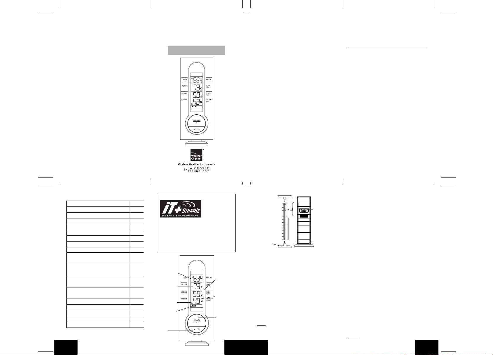
12 or 24 Hour
Display
Time
Indoor
Temperature
(˚F or ˚C)
Connection w
Icon
Sensor
Low Battery
Indicator
Set/Channel
Button
Figure 1
/
Outdoor
Temperature
(˚F or ˚C)
Outdoor
midity
Hu
(%RH)
Minimum/
Maximum &
Button
Plus
P.3
N
GB
Wireless
Thermo-hygro
Sensor
TX29UD-TH-IT
Mounting
Bracket
INVENTORY OF CONTENTS
1. Wireless Weather Station (Figure 1)
2. Wireless Thermo-Hygro Sensor (TX29UD-TH and mounting bracket. (Figure 2)
IT)
3. 3 each, 1/2" Philips screws.
4. One strip of double sided adhesive tape.
5. Instruction Manual and Warranty Card.
ADDITIONAL EQUIPMENT
(not in
cluded)
1. 1 Philips screwdriver.
2. 2 Fresh “AA” 1.5V Alkaline Batteries.
3. 2 Fresh “AAA” 1.5V Alkaline Batteries.
QUICK SETUP
Hint:
Use good quality Alkaline Batteries; avoid
rechargea
ble batteries.
P.4
GB
Figure 2
1. Have the Wireless Weather Sta tio n an d
rmo-hygro sensor 3 to 5 feet apart.
the
2. Batteries should be out of both units for 10
mi
nutes.
3. Place the batter ies into the thermo-hygro
sensor
first and next int o th e Wir ele ss
Weather Station.
4. DO NOT PRESS ANY BUTTONS FOR 15
MINUTES.
In
this time the Wireless Weather Station and
th e r m o-hy gro s e n sor w i ll b e g i n to
th e
com
municate with each other, and the display
will
show both the indoor temperature and an
outdoor temperature. If the Wireless Weather
Station
does not display both temperatures after
the
15 minutes, please retry the set up as stated
ov e. Afte r bo th ind oor and out doo r
ab
tempe
ratures are displayed for 15 minutes you
can
place your thermo-hygro sensor outdoors,
set your time.
and
The
thermo-hygro sensor should be placed in a
dry, shaded area (ex: under the eve of a roof).
The
thermo-hygro sensor has a range of 330
feet. Any walls that the signal will have to pass
will reduce distance. An outdoor wall
through
or
window will have up to 20 feet of resistance
an inter ior wall will have up to 10 feet of
and
resistanc
e. Your distance plus resistance should
not
exceed 330 feet in a straight line.
NOTE:
Fog and mist will not harm your thermo-
P.5
GB
Page 2
hygro sensor, but direct rain must be avoided.
DETAILED SETUP GUIDE
I. BATTERY INSTALLATION (When one
thermo-hygro sensor is being used)
1. First, insert the batteries to the thermo-hygro
sensor (see “A. thermo-hygro sensor”
below).
2. Within 2 minutes of powering up the sensor,
insert the batteries to the Wireless Weather
Station (see “B. Wireless W eather Station”
below). Once the batteries are in place, all
segments of the LCD will light up briefly.
Following the indoor temperature and the
time as 12:00 will be displayed. If they are
not shown in LCD after 60 seconds, remove
the batteries and wait for at least 60 seconds
before reinserting them. Once the indoor
data is displayed user may proceed to the
next step.
3. After the batteries are inserted, the Weather
Station will start receiving data signal from
the sensor. The outdoor temperature and
humidity should then be displayed on the
Weather Station. If this does not happen after
2 minutes, the batteries will need to be
removed from both units and reset from step
1 and the signal reception icon is no longer
shown.
P.6
GB
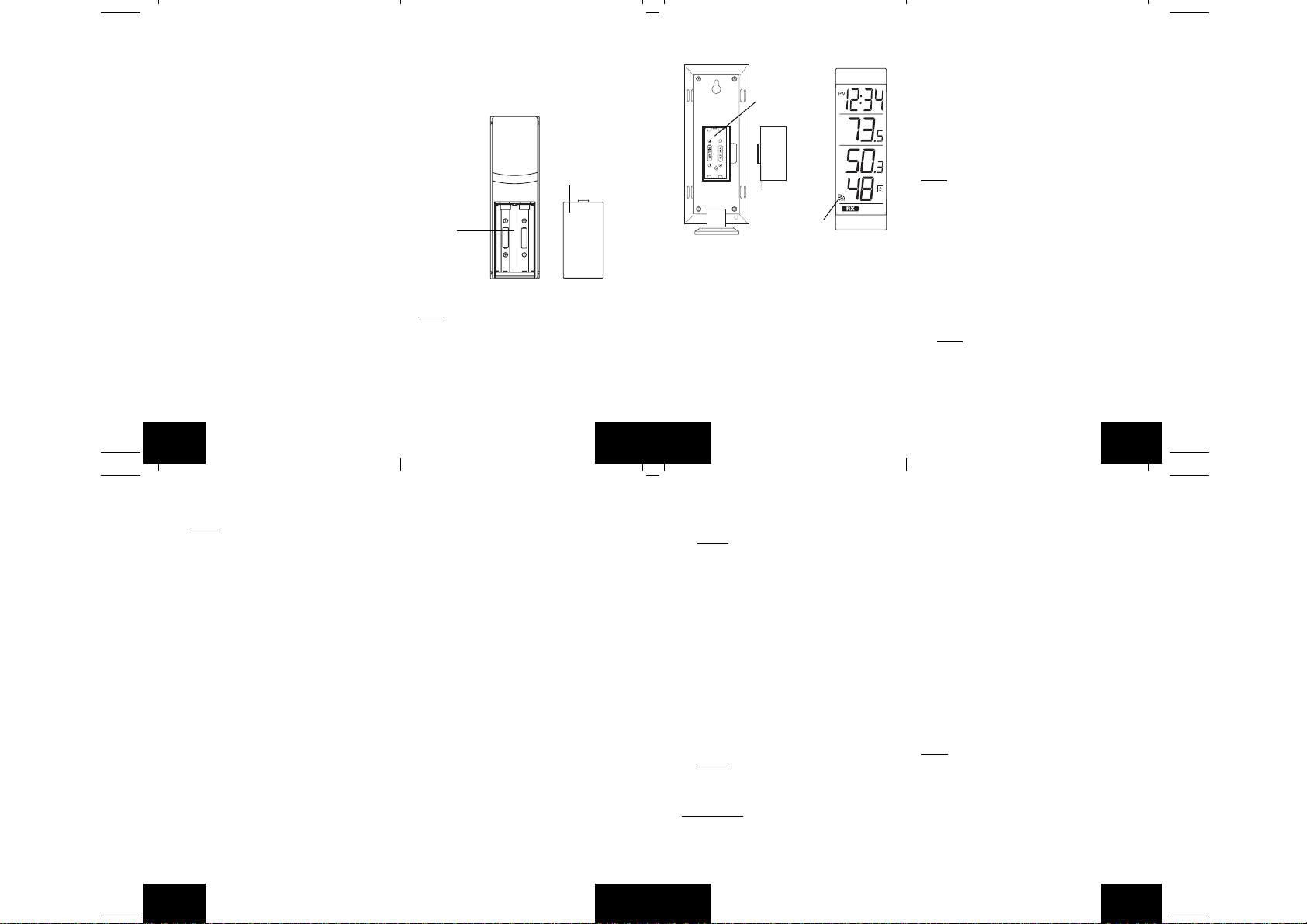
A. THERMO-HYGRO SENSOR
1. Remove the Battery Cover.
2. Observing the correct polarity, install 2 “AA”
Alkaline Batteries-make sure they do not
spring free, or start-up problems may occur.
Replace the Battery Cover.
Battery Cover
Battery
Compartment
B. WIRELESS WEATHER STA TION
Note:
After the batteries are installed, DO NOT
press any buttons. This may interfere with the
signals, causing temperatures to register
incorrectly.
1. Remove the Battery Cover on the back of
the Wireless Weather Station.
2. Observing the correct polarity, install 2 “AAA”
Alkaline Batteries.
SIZE AA LR6
SIZE AA LR6
P.7
GB
3. Replace Battery Cover.
4. Wait 15 minutes before pressing any buttons.
Battery
Compartment
Battery Cover
Sensor signal
reception icon*
* When the signal is successfully received by
the Weather Station, the icon will be switched
on. (If not successful, the icon will not be
shown in LCD) So the user can easily see
whether the last reception was successful
(icon on) or not (icon off). On the other hand,
the short blinking of the icon shows that a
reception is being done now.
• If the signal reception is not successful on
the first frequency (915MHz) for 45 seconds,
the frequency is changed to 920MHz and
the learning is tried another 45 seconds. If
still not successful the reception is tried for
P.8
GB
45 seconds on 910MHz. This will also be
done for re-synchronization.
C. SELECTING 12 OR 24 HOUR TIME
DISPLAY
1. Press and hold the SET/CH button for about
5 seconds.
2. “12h” will begin to flash in the TIME section
of the LCD
3. Press the MIN/MAX/+ button to toggle
between “12h” and “24h” time.
Note:
• Selecting 12 hour time will automatically
select ˚F as your temperature unit.
• Selecting 24 hour time will automatically
select ˚C as your temperature unit.
4. Press and release the SET/CH button again
to enter Time Setting.
D. TIME SETTING
1. After exiting the 12/24 Hour Setting, the hour
will begin flashing in the time display.
2. Press and release the MIN/MAX/+ button to
select the desired hour.
Note:
PM will appear to the left of the time
display for PM hours. For AM hours, that
area will remain blank.
3. Press and release the SET/CH button again,
and the minutes will begin to flash.
4. Press and release the MIN/MAX/+ button to
select the desired minutes.
P.9
GB
5. Press and release the SET/CH button to exit
the SET UP mode.
Note:
If no buttons are pressed for 10
seconds, the Wireless Weather Station will
automatically return to the normal display.
II. FEATURES
A. MINIMUM AND MAXIMUM
TEMPERATURES AND HUMIDITY
1. Press and release the MIN/MAX button,
“MIN” appears at the bottom of the LCD and
the recorded minimum temperatures and
humidity are displayed.
2. Press and release the MIN/MAX button
again to view maximum recorded
temperatures and humidity. “MAX” appears
at the bottom of the LCD and the maximum
temperatures and humidity are displayed.
3. Press and release the MIN/MAX button once
more to return to the current temperatures
and humidity.
B. RESETTING THE MINIMUM AND
MAXIMUM TEMPERATURES AND
HUMIDITY
To reset both the minimum and maximum
temperatures and humidity-press and hold the
MIN/MAX button for 5 seconds.
P.10
GB
C. ADDING ADDITIONAL REMOTE
SENSORS (OPTIONAL)
The WS-7220U-IT is able to receive signals from
2 additional thermo-hygro sensors. The f ollowing
are instructions for the set-up of thermo-hygro
sensor units with the WS-7220U-IT. These e xtra
sensors can be purchased through the same
dealer as this unit.
1. Remove all the batteries from the receiver
and sensor(s) and wait 60 seconds. During
these 60 seconds, press any button 20 times
to discharge any excess power.
2. Insert the batteries to the first thermo-hygro
sensor.
3. Within 2 minutes of powering up the first
sensor, insert the batteries to the Weather
Station. Once the batteries are in place, all
segments of the LCD will light up briefly.
Following the indoor temperature and the
time as 12:00 will be displayed. If they are
not shown in LCD after 60 seconds, remove
the batteries and wait for at least 60 seconds
before reinserting them.
4. The outdoor temperature and humidity from
the first sensor (channel 1) should then be
displayed on the W eather Station. If this does
not happen and the signal reception icon is
not shown, after 2 minutes, the batteries will
need to be removed from both units and
reset from step 1.
5. Insert the batteries to the second sensor as
P.11
GB
soon as the outdoor temperature and
humidity readings from the first sensor are
displayed on the Weather Station.
NOTE:
You must insert the batter ies into
the second sensor within 30 seconds of
reception of the first sensor.
6. The outdoor temperature and humidity from
the second sensor and the “channel 2” icon
should then be displayed on the Weather
Station. If this does not happen after 2
minute, the batteries will need to be removed
from all the units and reset from step 1.
7. Inser t the batteries to the third sensor as
soon as the “channel 2” icon and outdoor
data are displayed on the Weather Station.
Then within 2 minutes, the channel 3 outdoor
data from the third sensor will be displayed
and the channel icon will shift back to “1”
once the third transmitter is successfully
received. If this is not happen, user shall
restart the setting up from step 1.
NOTE:
You must insert the batter ies into
the third sensor within 30 seconds of
reception of the second sensor.
IMPORTANT:
if the setting for multiple sensors is not follow ed
as described above. Should transmission
problems occur, it is necessary to remove the
batteries from all units and start again the setup from step 1.
GB
Transmission problems will arise
P.12
D. VIEWING AND OPERATING WITH
MULTIPLE REMOTE SENSOR UNITS
1. To view the temperature of a different thermohygro sensor unit, press and release the SET/
CH button. A shift from one “boxed” number
to the next should be observed on the right
side of the OUTDOOR LCD.
2. To view the Minimum/Maximum temperature
& humidity: first select from which thermohygro sensor to read data (indicated by the
“boxed” number). Pressing and releasing the
MIN/MAX button will toggle through the
minimum and maximum indoor temperature,
and the minimum and maximum outdoor
temperature and humidity.
3. To reset the Minimum/Maximum readings,
press and hold the MIN/MAX button for 5
seconds.
III. MOUNTING
Note:
To achieve a true temperature reading,
avoid mounting in direct sunlight. We recommend
that you mount the thermo-hygro sensor on an
outside North-facing wall (under the eve of a
house is ideal). The sending range is 330 feet;
obstacles such as walls, stucco walls, concrete,
and large metal objects will reduce the range.
Place the Wireless W eather Station and thermohygro sensor in their desired locations before
permanently mounting.
P.13
GB
Page 3
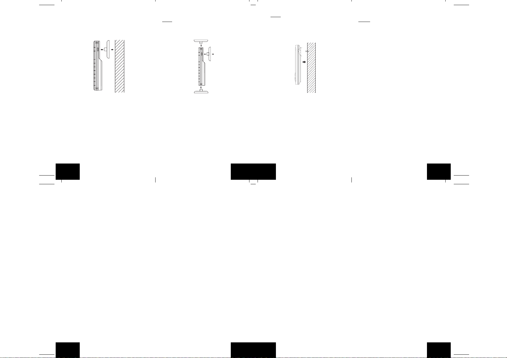
A. THERMO-HYGRO SENSOR
The thermo-hygro sensor can be mounted in
two ways:
• with the use of screws, or
• using the adhesive tape.
A. MOUNTING WITH SCREWS
1. Remove the mounting bracket from the
remote thermo-hygro sensor.
2. Place the mounting bracket over the desired
location.
3. Through the three screw holes of the bracket,
mark the mounting surface with a pencil.
4. Screw mounting bracket onto the mounting
surface. Ensure that the screws are flush
with the bracket.
5. Inser t the thermo-hygro sensor into the
bracket.
P.14
GB
B. MOUNTING WITH ADHESIVE TAPE
Note:
The adhesive tape is not intended to be
used as a permanent mounting solution. Only
use the adhesive tape while you are positioning
the Weather Station and thermo-hygro sensor.
1. With a nonabrasive solution, clean and dry
the back of the mounting bracket and the
mounting surface to ensure a secure hold.
The mounting surface should be smooth and
flat.
2. Remove the protective strip from one side
of the tape.
3. Adhere the tape to the designated area on
the back of the mounting bracket.
4. Remove the protective strip from the other
side of the tape.
5. Position the remote thermo-hygro sensor in
the desired location, ensuring that the
Weather Station can receive the signal.
P.15
GB
Note:
Mounting with adhesive tape is not
recommended as a permanent mounting
solution. Only use the adhesive tape during
set-up process
B. WIRELESS WEATHER STA TION
1. The Wireless Weather Station comes with
the table stand attached to the back of the
Receiver. If you wish to use the table-stand,
simply place the Wireless Weather Station
in an appropriate location, and pull out on
the attached stand.
2. To wall mount, push the table stand flat
against the Wireless Weather Station (if it
isn’t already flat). Fix a screw (not included)
into the desired wall, and place the Wireless
Weather Station onto the screw using the
hanging hole on the backside. Gently pull
the Wireless Weather Station down to lock
the screw into place.
P.16
GB
TROUBLESHOOTING
NOTE:
For problems not solv ed, please contact
La Crosse Technology via e-mail or phone, or
visit our website, www.lacrossetechnology.com
Problem: The LCD is faint
Solution: Replace batteries
Problem: No outdoor temperature is displayed.
Solution:
1. Bring any units from outside, inside and
place the units 3 to 5 feet apart with nothing
in-between them.
2. Remove the batteries from all units.
3. Press one of the buttons on the Wireless
Weather Station display at least 20 times to
clear all memory. Verify that the display is
blank before proceeding.
4. Using good quality alkaline batteries, place
the batteries back into the outdoor
temperature sensor; making sure they are
installed according to the diagrams in the
battery compartment.
5. Taking care not to press any buttons , reinstall
the batteries in the Wireless Weather Station
according to the diagram in the battery
compartment.
6. Do not press any buttons for at least 15
minutes after installing the batteries. (This
is to let the units establish a good
connection.)
P.17
GB
7. During the course of the 15 minutes an
outdoor temperature should appear on the
display . You can now put your sensor(s) bac k
outside.
MAINTENANCE AND CARE
INSTRUCTIONS
• Extreme temperatures, vibration, and shock
should be avoided to prev ent damage to the
units.
• Clean displays and units with a soft, damp
cloth. Do not use solvents or scouring
agents; they may mark the displays and
casings.
• Do not submerge in water.
• Do not subject the units to unnecessary heat
or cold by placing them in the oven or freezer .
• Opening the casings invalidates the
warranty. Do not try to repair the unit.
Contact La Crosse Technology for repairs.
SPECIFICATIONS
Transmitting Frequency 915 MHz
TEMPERATURE MEASURING RANGES
Indoor 14.1˚F to 139.8˚F with
Outdoor -39.8˚F to 139.8˚F with
HUMIDITY MEASURING RANGE
Outdoor (%RH) 1% to 99%
Transmitting range Maximum 330 feet
GB
0.2˚F resolution.
0.2˚F resolution.
P.18
TEMPERATURE CHECKING INTERVAL
Indoor Every 15 seconds
Outdoor Every 4 seconds
BATTERIES-(Alkaline recommended)
Thermo-Hygro Sensor 2 x AA, 1.5V
Wireless Weather Station 2 x AAA, 1.5V
DIMENSION: (H x W x D)
Wireless Weather Station 5.90" x 2.36" x 0.81"
Thermo-Hygro Sensor 5.05" x 1.5" x 0.83"
Battery life Up to 24 Months
(100m) open space
(150 x 60 x 20.7mm)
(128.3 x 38.2 x 21.2mm)
WARRANTY INFORMATION
La Crosse Technology, Ltd provides a 1-year
limited warranty on this product against
manufacturing defects in materials and
workmanship.
This limited warranty begins on the original date
of purchase, is valid only on products purchased
and used in North America and only to the
original purchaser of this product. To receive
warranty service, the purchaser must contact
La Crosse Technology, Ltd for problem
determination and service procedures.
Warranty service can only be performed by a
La Crosse Technology, Ltd authorized service
center. The original dated bill of sale must be
presented upon request as proof of purchase
P.19
GB
to La Crosse Technology, Ltd or La Crosse
Technology, Ltd’s authorized service center.
La Crosse Technology, Ltd will repair or replace
this product, at our option and at no charge as
stipulated herein, with new or reconditioned
parts or products if found to be defective during
the limited warranty period specified above. All
replaced parts and products become the
property of La Crosse T echnology, Ltd and must
be returned to La Crosse Technology, Ltd.
Replacement parts and products assume the
remaining original warranty , or ninety (90) da ys ,
whichever is longer . La Crosse Technology, Ltd
will pay all expenses for labor and materials f or
all repairs covered by this warranty. If necessary
repairs are not covered by this warranty, or if a
product is examined which is not in need or
repair, you will be charged for the repairs or
examination. The owner must pay any shipping
charges incurred in getting your La Crosse
Technology, Ltd product to a La Crosse
Technology, Ltd authorized service center. La
Crosse Technology, Ltd will pay ground return
shipping charges to the owner of the product to
a USA address only.
Your La Crosse T echnology, Ltd warranty covers
all defects in material and workmanship with the
following specified exceptions: (1) damage
caused by accident, unreasonable use or
P.20
GB
neglect (including the lack of reasonable and
necessary maintenance); (2) damage occurring
during shipment (claims must be presented to
the carrier); (3) damage to, or deterioration of,
any accessory or decorative surface; (4)
damage resulting from failure to follow
instructions contained in your owner’s manual;
(5) damage resulting from the performance of
repairs or alterations by someone other than an
authorized La Crosse Technology, Ltd
authorized service center; (6) units used for
other than home use (7) applications and uses
that this product was not intended or (8) the
products inability to receive a signal due to any
source of interference.. This warranty covers
only actual defects within the product itself, and
does not cover the cost of installation or removal
from a fixed installation, normal set-up or
adjustments, claims based on misrepresentation
by the seller or performance variations resulting
from installation-related circumstances.
LA CROSSE TECHNOLOGY, LTD WILL NOT
ASSUME LIABILITY FOR INCIDENTAL,
CONSEQUENTIAL, PUNITIVE, OR OTHER
SIMILAR DAMAGES ASSOCIATED WITH THE
OPERATION OR MALFUNCTION OF THIS
PRODUCT. THIS PRODUCT IS NOT TO BE
USED FOR MEDICAL PURPOSES OR FOR
PUBLIC INFORMATION. THIS PRODUCT IS
NOT A TOY. KEEP OUT OF CHILDREN’S
REACH.
P.21
GB
Page 4

This warranty gives you specific legal rights. You
may also have other rights specific to your State.
Som e
Sta te s do no allow th e exclus io n of
consequential or incidental damages therefore
the above exclusion of limitation may not apply
to
you.
For warra nt y wor k, tech nic al suppo rt, or
in
formation contact:
Technology
La Crosse
2809
Losey Blvd. S.
La Crosse, WI 54601
Phone: 608.782.1610
Fax: 608.796.1020
e-mail:
support@lacrossetechnology.com
(warranty work)
sales@lacrossetechnology.com
(information on other products)
www.lacrossetechnology.com
Questions? Instructions? Please visit:
www.lacrossetechnology.com/7220
P.22
GB
web:
All rights reserved. This handbook must not be
reproduced in any for m, even in excerpts, or
dup li ca te d
mechanical
written permission of the publisher.
Thi s
printing errors. The information in this handbook
is regularly checked and corrections made in
the
technical mistakes or printing errors, or their
consequences.
All
or proces se d usin g electr on ic ,
or chemical procedure s with out
handboo k may co nt ain mista kes and
nex t issue. We ac ce pt no liab il ity for
trademarks and patents are acknowledged.
P.23
GB
TABLE DES MATIÈRES
Sujet Page
Introdu
ction 25
Inventaire 26
Installatio
n 27
Guide de pa
Installation des pile
Format d’e l’heure 12H ou 24 H 31
Réglage
Fonctionnalités 32
Rel
de tempé
Réinitialisation des rel
et maxi
d’
hygrométrie 33
Capteurs distants suppléméntaire
Capteurs distants
affichage et
Fixatio
Dépistage des panne
Soin et entretie
Ca
In
formations sur la garantie 43
F
ramétrage détaillé 28
s 28
de l’heure 32
evés minimums et maximum
rature et d’hygrométrie 32
evés minimums
mum de température et
s 33
multiples -
fonctionnement 35
n 36
s 40
n 41
ractéristiques techniques 41
P.24
Le produit
transmission sans fil de pointe conçue et
dé
T E C H N O L O G Y .
TRANSMISSIO
immédiate
toutes les données extérieures relevées par
le s cap teurs : su i vez les v a r i a t i ons
vous offre:
I N S T A N T
TRAN
SMISSION
es t la nou vel l e
te chn olo gie de
veloppée en exclusivité par LA CROSSE
N
I N S T A N T
assure la mis e à jour
( tou tes les 4 secondes !) de
climatiques en temps réel!
Format
d’affichage
12H ou 24H
Température
inté
rieure (˚F
ou ˚C)
Icône de
conn
exion au
capteur
Témoin piles
faibles
Touche de
sélection du
al
can
Figure 1
Température
extérieure
(˚F or ˚C)
Humidité
relati
extérieure
(%RH
Touche
Mi
nimum/
Maximum
& Plus
P.25
ve
)
F
Support de
fixation
Capteur
hygro-
the
rmique sans
fil
TX29UD-TH-IT
Figure 2
INVENTAIRE
1. Le poste de température sans fil (Figure 1)
2. L e ca pt eur hygr o -th e r miq u e sans fi l
(TX29UD-TH-IT) avec support de fixation.
(Figure 2)
3. 3 vis cruciformes de 1,25 cm.
4. Une longueur de bande adhésive double
face.
5. Manuel d’instructions et fiche de garantie.
MATÉRIEL SUPPLÉMENTAIRE
(non
fourni)
1. 1 tournevis cruciforme.
2. 2 piles alcalines 1,5 V neuves de type “AA”.
3. 2 piles alcalines 1,5 V neuves de type “AAA”.
P.26
F
INSTALLATION
: Utilisez des piles alcalines de marque;
Conseil
évitez
les piles rechargeables.
1. Placez le capteur hygro-thermique à 1 m - 1
m 50 de la station météo sans fil.
2. Le s pil es doivent être retirées des deux
depuis 10 minutes.
unités
3. Insérez en premier les piles du capteur
hygro-thermique, puis celles de la station
météo sans fil.
sous tension tous les capteurs avant
(Mettez
la station météo sans fil.)
4. N ’A PPU YE R SUR AUC UN E TOUC HE
PEN
DANT 15 MINUTES.
Pendant ce temps, la station météo sans fil et
capteur hygro-thermique commenceront à
le
‘dialoguer’,
tem pé
extérieure. Si le poste de température n’affiche
pa
répétez
Lo rsq ue les
extérieure ont été affichées pendant 15 minutes,
vous pouvez insta ller votre cap teur hygrothe
Le
un
d’un
the
le poste de température affichant la
rature intér ieure et une tempé rat ure
s les deux températures dans les 15 minutes,
la procédure d’installation ci-dessus.
tem pé rat ure s int ér ieure et
rmique à l’extérieur et régler l’heure.
capteur hygro-thermique doit être placé dans
endroit sec et ombragé (ex. sous la corniche
toit). Le rayon d’émission du capteur hygro-
rmi que est de 100 mètres. Tout mur s e
P.27
trou
vant sur la trajectoire du signal réduira sa
po
rtée. Un mur extérieur ou une fenêtre peut
la portée de 6 mètres au plus et un mur
réduire
intérieur
de 3 mètres. La distance, en tenant
compte
de ces réductions, ne doit pas excéder
100 mètres en ligne droite.
NOTE:
Le brouillard et la brume n’auront aucun
fet nuisible sur le capteur hygro-thermique
ef
mais la pluie doit être évitée.
GUIDE DE PARAMÉTRAGE DÉTAILLÉ
I. INSTALLATION DES PILES (Quand on
utilise un capteur thermo-
1. Commencer par installer les piles du capteur
the
rmo-hygro (voir “A. Capteur thermo-
hygro” ci-dessous).
2. Dans les 2 minutes qui suivent la mise sous
tension
du capteur, i nstaller les pi les du
de t empérature (voir “B. Poste de
poste
températur
qu e
segments
Ensuit
(12:00)
sur
reti rer
secondes
Une
affichée
e sans fil” ci-dessous). Une fois
les pi le s sont en place , to us les
du LCD s’affichent brièvement.
e, la température intérieure et l’heure
s’affichent. Si elles ne s’affichent pas
le LCD dans les 60 secondes qui suivent,
les pi les e t attend re au moins 60
avant de les remettre en place.
fois que les données intérieures sont
s, passer à l’étape suivante.
hygro)
tempé
rature commence à recevoir le signal
des
données du capteur. La température et
l’humidité
extérieures devraient s’afficher sur
pos te de temp éra tur e. Si el les ne
le
s’affichent
les
recommencer
de réception du signal n’est plus affichée.
A. Capteur Thermo-hygro
1. Retirez le support de fixation. Le support se
détache et s’attache
2. Retirez le couvercle du compartiment à piles
en
3. Installez 2 piles de type AA en respectant la
pola
(afin
vérifiez qu’elles restent bien en place).
4. Remplacez le couvercle du compartiment en
le
de
Compartiment à
pile
s
pas dans les 2 minutes, retirer
p i l e s d e t ou s l e s a p p a r e i l s e t
à partir de l’étape 1 ; l’icône
facilement.
le faisant glisser vers le bas.
rité. Les piles s’enclenchent fermement
d’éviter tout problème au démarrage,
faisant glisser vers le haut. Assurez-vous
sa bonne fermeture.
Cou
vercle du
compa
rtiment à
pile
s
6
6RL
R
L AA EZIS
A
A
EZIS
3. Quand les piles sont en place, le poste de
F
P.28
F
P.29
F
Page 5

B. POSTE DE TEMPÉRATURE SANS FIL
Remarque:
TOUCHEZ AUCUNE touche au risque
d’entraver les signaux et provoquer une erreur
d’enregistrement des températures.
1. Retirez le couvercle du compartiment à piles
2. Installez dans le compar timent 2 piles
3. Remettez le couvercle du compartiment à
4. Attendez 15 minutes avant de toucher une
F
Après avoir installé les piles, NE
à l’arrière du poste de température sans fil.
alcalines de type “AAA” en respectant la
polarité.
piles.
touche quelconque.
Compartiment à
piles
Couvercle du
compartiment
à piles
Icône de
réception du
signal du
capteur*
P.30
* Quand le poste de température reçoit le
signal, l’icône s’allume. (Sinon, l’icône
n’apparaît pas sur le LCD). De cette façon,
l’utilisateur peut voir facilement si la dernière
réception a réussi (icône affiché) ou non
(icône absent). Par ailleurs, un icône qui
clignote rapidement indique qu’une
réception est en cours.
• En cas de non réception du signal sur la
première fréquence (915 MHz) dans les 45
secondes, la fréquence passe à 920MHz et
un nouvel essai d’apprentissage est effectué
pendant 45 secondes. En cas d’insuccès,
un nouvel essai de réception est effectué
pendant 45 secondes sur 910MHz. Ces
essais sont aussi effectués pour resynchronization.
B. FORMAT DE L’HEURE 12H/24H
1. Appuyez sur la touche SET/CH pendant 5
secondes environ.
2. “12h” clignote à la section HEURE de l’écran
LCD
3. Appuyez sur la touche MIN/MAX/+ pour
basculer entre le format “12h” et “24h”.
Remarque:
•Avec le format 12H, la température sera
automatiquement affichée en ˚F.
•Avec le format 24H, la température sera
automatiquement affichée en ˚C.
P.31
4. Appuyez de nouveau sur la touche SET/CH
pour passer au Réglage de l’Heure.
C. RÉGLAGE DE L’HEURE
1. Après avoir sélectionné le Format de l’heure
12/24 H, les heures clignotent à la section
HEURE de l’écran LCD.
2. Appuyez sur la touche MIN/MAX/+ pour
régler les heures.
Remarque:
heures entre midi et minuit (PM). Le symbole
s’éteint pour les heures entre minuit et midi
(AM).
3. Appuyez de nouveau sur la touche SET/CH
4. Appuyez sur la touche MIN/MAX/+ pour
5. Appuyez de nouveau sur la touche SET/
Remarque:
station météo sans fil revient automatiquement
à l’affichage normal.
II. FONCTIONNALITÉS
A. RELEVÉS MINIMUM ET MAXIMUM DE
1. Appuyez momentanément sur la touche
F
F
Le symbole PM s’affiche pour les
; les minutes clignotent.
régler les minutes.
CH pour quitter le mode PARAMÉTRAGE.
Après 10 secondes d’inactivité, la
TEMPÉRATURE ET D’HYGROMÉTRIE
MIN/MAX ; “MIN” s’affiche en bas de l’écr an
LCD avec les relevés minimums de
température et d’hygrométrie à leurs
sections respectives.
P.32
2. Appuyez de nouveau sur la touche MIN/MAX
pour afficher les relevés maximums de
température et d’hygrométrie. “MAX”
s’affiche en bas de l’écran LCD avec les
relevés maximums de température et
d’hygrométrie à leurs sections respectives
3. Appuyez encore une fois sur la touche MIN/
MAX pour revenir aux températures et
hygrométrie actuelles.
B. RÉINITIALISATION DES RELEVÉS
MINIMUM ET MAXIMUM DE
TEMPÉRATURE ET D’HYGROMÉTRIE
Pour réinitialiser les relevés minimums et
maximums de température et d’hygrométrie,
appuyez sur la touche MIN/MAX pendant 5
secondes.
C. AJOUTER DES CAPTEURS A DISTANCE
SUPPLEMENTAIRES (EN OPTION)
Le WS-7220U-IT peut recevoir les signaux de 2
capteurs thermo-hygro supplémentaires. Suivre
les instructions suivantes pour monter les
capteurs thermo-hygro avec le WS-7220U-IT.
On peut se procurer ces capteurs
supplémentaires chez le dépositaire de cet
appareil.
1. Retirer toutes les piles du récepteur et du/
des capteur(s) et attendre 60 secondes.
Durant ces 60 secondes, appuyer sur
n’importe quelle commande 20 fois pour
P.33
F
décharger toute énergie excessive.
2. Installer les piles du premier capteur thermohygro.
3. Dans les 2 minutes qui suivent la mise sous
tension du premier capteur, installer les piles
du poste météo. Une fois que les piles sont
en place, tous les segments du LCD
s’allument brièvement. Ensuite, la
température intérieure et l’heure (12:00),
s’affichent. Si elles ne s’affichent pas sur le
LCD dans les 60 secondes qui suivent,
retirer les piles et attendre au moins 60
secondes avant de les remettre en place.
4. La température et l’humidité extérieures du
premier capteur (canal 1) devraient s’afficher
sur le poste de température. Si elles ne
s’affichent pas dans les 2 minutes qui
suivent, retirer les piles de tous les appareils
et recommencer à partir de l’étape 1.
5. Installer les piles du deuxième capteur dès
que les relevés de température et d’humidité
extérieures du premier capteur s’affichent
sur le poste de température.
NOTE:
Il est impératif d’installer les piles
dans le deuxième capteur dans les 30
secondes qui suivent la réception du premier
capteur.
6. La température et l’humidité extérieures du
deuxième capteur et l’icône “channel 2”
devraient s’afficher sur le poste météo. Si elles
ne s’affichent pas dans les 2 minutes qui
P.34
F
suivent, retirer les piles de tous les appareils
et recommencer à partir de l’étape 1.
7. Installer les piles dans le troisième capteur
dès que l’icône “channel 2” et les données
extérieures s’affichent sur le poste météo.
Dans les 2 minutes qui suivent, les données
extérieures du canal 3 du troisième capteur
devraient s’afficher et le canal retourner à
“1” après réception du troisième émetteur.
Sinon, recommencer le montage à partir de
l’étape 1.
NOTE:
Il est impératif d’installer les piles
dans le troisième capteur dans les 30
secondes qui suivent la réception du
deuxième capteur.
IMPORTANT:
se produiront si le réglage des capteurs
multiples n’est pas effectué conformément aux
instructions ci-dessus. En cas de problème de
transmission, retirer les piles de tous les
appareils et recommencer à partir de l’étape 1.
D. CAPTEURS DISTANTS MULTIPLES -
AFFICHAGE ET FONCTIONNEMENT
1. Pour afficher le relevé de température d’un
capteur hygro-thermique différent, appuyez
momentanément sur la touche SET/CH. Le
chiffre encadré affiché à droite de la section
EXTÉRIEUR de l’écran LCD devrait
changer.
Des problèmes de transmission
P.35
2. Pour afficher les relevés Minimum/Maximum
de température et d’hygrométrie,
sélectionnez d’abord le capteur hygrothermique concerné (indiqué par le chiffre
encadré). Appuyez à plusieurs reprises sur
la touche MIN/MAX pour faire défiler les
relevés minimum et maximum de
température et d’hygrométrie intérieures et
extérieure enregistrées.
3. Pour réinitialiser les relevés minimum et
maximum, appuyez sur la touche MIN/MAX
pendant 5 secondes.
III. FIXATION
Remarque:
température, évitez d’installer les unités en plein
soleil. Nous vous conseillons de fix er le capteur
hygro-thermique sur un mur exposé au nord
(sous une corniche est un endroit idéal). Le
rayon de transmission est de 100 mètres - des
obstacles tels que murs, structures en béton ou
métalliques réduiront ce rayon. Essayez la
station météo sans fil et le capteur hygrothermique aux emplacements choisis avant de
les fixer de façon permanente.
A. CAPTEUR HYGROTHERMIQUE
Le capteur distant peut être fixé de deux façons :
•à l’aide de vis
•à l’aide de bande adhésive
F
F
Pour obtenir des relevés précis de
P.36
1. FIXATION A VIS
a. Retirez le support du capteur de température
distant.
b. Placez le support à l’endroit choisi.
c. A l’aide d’un cray on, marquez l’emplacement
des trous de vis à travers les trois trous de
fixation du support.
d. Vissez le suppor t à la surface de fixation.
Assurez-vous que les têtes de vis sont à ras
le support.
e. Enclenchez le capteur de température
distant sur son support.
2. FIXATION A L’AIDE DE BANDE
ADHÉSIVE
P.37
F
Page 6

a. Afin d’assurer une bonne prise, nettoyez le
dos du support et la surface de fixation à
l’aide d’une solution non-abrasive, puis
laissez sécher. La surface de fixation doit
être plane et lisse.
b. Retirez le film protecteur de l’une des faces
de la bande.
c. Collez la bande à l’emplacement prévue au
dos du support.
d. Retirez le film protecteur de l’autre face de
la bande.
e. Positionnez le capteur de température
distant à l’emplacement choisi en vous
assurant auparavant que la station météo
intérieure peut recevoir le signal.
Note:
la fixation à l’aide de la bande adhesive
n’est pas recommandée comme une solution
permanente. Utilisez seulement la bande
adhesive durant le paramétrage de la station.
B. POSTE DE TEMPERATURE SANS FIL
La station météo intérieure peut être fixée de
deux façons :
• positionnée sur le socle
• fixée au mur à l’aide d’une vis (non-fournie)
1. POSITIONNEMENT SUR LE SOCLE
La station météo intérieure est munie d’un socle
intégré. Positionnez la station météo intérieure
sur son socle dans un endroit propice.
P.38
F
2. FIXATION MURALE
1. Retirez le socle en le tirant vers le bas et en
le faisant pivoter vers l’avant.
2. Vissez une vis (non-fournie) dans le mur
choisi, en laissant dépasser la tête d’environ
5 mm.
3. Placez la station météo intérieure sur la vis
à l’aide de l’encoche de suspension située
P.39
à l’arrière.
4. Tirez la station délicatement vers le bas pour
la verrouiller en place.
DÉPISTAGE DES PANNES
REMARQUE:
solution, veuillez contacter La Crosse
Technology par e-mail ou téléphone ou visitez
notre site web,
Problème: L’écran LCD est faible
Solution: Remplacez les piles
Problème:
La température extérieure n’est pas affichée.
Solution:
1. Rentrez à l’intérieur tous les capteurs
2. Retirez les piles de toutes les unités.
3. Appuyez au moins 20 fois sur l’une des
4. Remettez es piles alcalines de marque dans
5. Sans toucher aucune touche, réinstallez les
F
F
Pour les problèmes restés sans
www.lacrossetechnology.com
extérieurs, puis placez-les unités dans un
rayon de 1 m à 1,50 m l’une de l’autre, sans
obstacle entre elles.
touches de la station météo sans fil afin
d’effacer la mémoire. Vérifiez que l’écran
est vide avant de continuer.
le compartiment à piles du capteur extérieur
en prenant soin de respecter les schémas à
l’intérieur du compartiment.
piles dans la station météo sans fil, en
P.40
respectant le schéma à l’intérieur du
compartiment à piles.
6. Après l’installation des piles, ne touchez
aucune touche pendant au moins 15
minutes. (P our permettre aux unités d’établir
une connexion fiable.)
7. Au cours de ces 15 minutes, une
température extérieure devrait s’afficher à
l’écran. Vous pouvez désormais replacer
votre(vos) capteur(s) à l’extérieur.
SOIN ET ENTRETIEN
• Évitez les extrêmes de température, les
vibrations et les chocs qui peuvent
endommager les unités.
• Nettoyez les écrans et les unités à l’aide d’un
chiffon doux humide. N’utiliser aucun solvant
ni produit à récurer qui peuvent marquer les
écrans et les boîtiers.
• Ne pas immerger les unités dans l’eau.
• Ne pas exposer inutilement les unités aux
extrêmes de température, par exemple en
les plaçant dans un four ou congélateur
•L’ouverture des boîtiers entraîne la nullité de
la garantie. Ne pas tenter de réparer
l’appareil. Pour toute réparation, contactez
La Crosse Technology.
CARACTÉRISTIQUES TECHNIQUES
Fréquence de transmission 915 MHz
P.41
F
PLAGE DE MESURE DES TEMPÉRATURES
Intérieur 9,9˚C à 59,8˚C à une
Extérieur -39,8˚C à 59,8˚F à une
PLAGE DE MESURE DE L’HYGROMÉTRIE
Extérieur (%RH) 1% à 99%
Rayon d’émission 100 m maximum
INTERVALLE DE RELEVÉ DE LA
TEMPÉRATURE
Intérieur 15 secondes
Extérieur 4 secondes
PILES-(Piles alcalines recommandées)
Capteur hygro-thermique 2 x AA, 1,5 V
Station météo sans fil 2 x AAA, 1,5 V
DIMENSIONS : (H x L x P)
Récepteur 150 x 60 x 20.7mm
Capteur hygro-thermique
Durée de vie des piles Jusqu’à 24 mois
F
résolution de 0,1˚C
(14,1˚F à 139,8˚F à une
résolution de 0,2˚F)
résolution de 0,1˚C
(-39,8˚F à 139,8˚F à une
résolution de 0,2˚F)
(5.90" x 2.36" x 0.81")
P.42
(330 ft.) en champ libre
128.3 x 38.2 x 21.2mm
(5.05" x 1.5" x 0.83")
(piles Alkaline)
INFORMATIONS SUR LA GARANTIE
La Crosse Technology, Ltd garantit ce produit
de façon limitée pendant 1 an contre les défauts
de fabrication et de matière.
Cette garantie limitée commence le jour du
premier achat, n’est valable que pour les
produits achetés et utilisés en Amérique du Nord
et ne couvre que l’acheteur originel de ce
produit. Pour toute intervention sous garantie,
l’acheteur doit contacter La Crosse Technology,
Ltd pour l’identification du problème et les
procédures de SAV. Les interventions sous
garantie ne peuvent être effectuées que dans
un centre de SAV agréé par La Crosse
Technology, Ltd. Le ticket de caisse d’origine
doit être présenté sur demande à La Crosse
Technology, Ltd ou à son centre de SA V comme
preuve d’achat.
La Crosse Technology, Ltd réparera ou
remplacera, à notre discrétion, ce produit
gratuitement comme spécifié par la présente
avec ou par des pièces ou produits neufs ou
remis à neuf si ce produit s’avère être
défectueux pendant la période de la garantie
limitée exposée ci-dessus. Toutes les pièces et
produits remplacés deviennent la propriété de
La Crosse Technology, Ltd et doivent être
restitués à La Crosse Technology, Ltd. Les
pièces et produits de rechange sont couverts
P.43
par la garantie d’origine restante ou pendant
quatre-vingt-dix (90) jours, soit la durée la plus
longue. La Crosse Technology, Ltd prendra en
charge tous les frais de main d’œuvre et de
matériels pour toute réparation couverte par
cette garantie. Si les réparations nécessaires
ne sont pas couvertes par cette garantie ou s’il
s’avère, lors de sa vérification, qu’un produit ne
nécessite aucune réparation, la réparation ou
vérification vous sera facturée. Le propriétaire
doit prendre en charge tous frais d’expédition
du produit La Crosse Technology, Ltd vers le
centre de SAV agréé La Crosse Technology , Ltd.
La Crosse Technology, Ltd prendra en charge
les frais de retour au propriétaire d’une adresse
des USA seulement.
Votre gar antie La Crosse T echnology, Ltd couvre
tous les défauts de matières et de fabrication
exceptés : (1) les dégâts causés par les
accidents, une utilisation déraisonnable ou
négligence (y compris un manque d’entretien
raisonnable et nécessaire) ; (2) les dégâts
survenant pendant le transport (toute
réclamation doit être faite au transporteur) ; (3)
dégâts à, ou détérioration de, tout accessoire
ou toute surface décorative ; (4) dégâts dus à
un manquement aux instructions contenues
dans votre manuel de l’utilisateur ; (5) dégâts
occasionnés suite à une réparation ou
modification effectuée par un intervenant autre
F
P.44
F
qu’un centre de SAV agréé La Crosse
Technology, Ltd ; (6) appareil utilisés pour un
usage autre que domestique (7) les applications
et usages auxquels cet appareil n’est pas
destiné ou (8) l’incapacité du produit à recevoir
un signal à cause d’une source d’interférences
quelconque. Cette garantie ne couvre que les
défauts du produit lui-même et ne couvre pas
les frais d’installation ou de désinstallation d’une
installation fixe, le paramétrage normal ou les
réglages, les litiges basés sur les malversations
du vendeur ou les variations de performance
résultant des circonstances relatives à
l’installation.
LA CROSSE TECHNOLOGY N’ACCEPTE
AUCUNE RESPONSABILITÉ POUR LES
DOMMAGES FORTUITS, CONSÉCUTIFS,
PUNITIFS OU AUTRES DOMMAGES
SIMILAIRES RELATIFS À L’UTILISATION OU
AU MAUVAIS FONCTIONNEMENT DE CE
PRODUIT. CE PRODUIT NE DOIT PAS ÊTRE
UTILISE À DES FINS MÉDICALES OU A TITRE
D’INFORMATION DU PUBLIC. CE PRODUIT
N’EST PAS UN JOUET. GARDER HORS DE
LA PORTÉE DES ENFANTS.
Cette garantie vous confère certains droits
spécifiques. Vous possédez peut-être d’autres
droits spécifiques à votre état. Certains états
ne permettent pas l’exclusion des dommages
P.45
F
Page 7

fortuits ou consécutifs, do nc l’exclu sio n de
limitations énoncée ci-dessus peut ne pas vous
conce
rner.
Pour toute intervention sous garantie, support
technique ou in
Questions ? Instructions ?
www.lacrossetechnology.com/7220
Tous droits réservés. Ce manuel ne peut être ni
reproduit sous quelque forme que ce soit, même
sous forme d’extraits, ni c opié, ni trait é par
pr o c édu r e
chimique, sans l’accord écrit de l’éditeur.
F
formation, veuillez contacter
Technology
La Crosse
2809
Losey Blvd. South
La Crosse, WI 54601
Phone: 608.782.1610
Fax: 608.796.1020
support@lacrossetechnology.com
(interventions sous garantie)
sales@lacrossetechnology.com
(informations sur les autres produits)
www.lacrossetechnology.com
e-mail :
site
web :
Visitez :
él ect r o niq u e , m é can i q ue o u
P.46
Ce
manuel peut contenir des erreurs et fautes
d’impression. Les informations contenues dans
ce manuel sont r égulièr ement vér ifiées, les
corrections étant apportées à l’édition suivante.
Nous n’acceptons aucune responsabilité pour
les
erreurs techniques ou d’impression ou pour
leurs conséquences.
Toutes les marques commerciales et brevets
sont
reconnus.
P.47
TABLA DE CONTENIDO
Tema Página
Introducció
Contenid
Guía Rápida pa
Funcionamient
Guía Detallada pa
Funcionamient
Instalación de las pilas 52
Formato de la Hora en 12 o 24 Horas 56
Ajuste de la Ho
Características 57
Mínimas & Máximas
y Humeda
Reajuste de los datos de las Mínimas
& Máximas
Como a
The
Visualización & Ope
sensores Thermo-Hygro 60
Instalació
Solución de Pro
Instrucciones de Cuidado &
Mantenimient
Especificaciones
Información de la Garantía 68
F
S
n 49
o 50
ra la puesta en
o 51
ra la puesta en
o 52
ra 56
Temperaturas
d 57
Temperaturas y Humedad 57
gregar sensores adicionales
rmo-Hygro 58
ración de varios
n 61
blemas 65
o 66
Técnicas 67
P.48
Este producto ofrece:
TRA N SM I S IO N
TA N TAN E A
IN S
ie s lo últ i mo en
transmisión
diseñado y desarrollado exclusivamente por
l a ‘ LA C RO SS E T EC HN OL OGY ’ .
TRANSMISION INSTANTANEA
un a act ua l iz a ci ó n in med iat a (¡c ad a 4
segundos!) de todos los datos del tiempo en
exter iores medidos por los transmisores:
sigue las variaciones del clima!
ra Formato
Ho
de 12 o 24
Temperatura
Inte
˚C
)
Icono indica la
Conexión con
el Sensor
Indicador de
Pilas Bajas
Botón Set/
Channel
inalámbrica, este producto es
rior (˚F o
Figura 1
t e cn o l o gi a d e
, le ofrece
Temperatura
rior (˚F
Exte
o ˚C)
Humedad
rior
Exte
(%RH
Botón de
Minimo/
Máximo &
Más
P.49
)
S
Sensor
Inalámb
rico
The
rmohygro
TX29UD-TH-IT
Sopo
rte de
Montaje
Figura 2
CONTENIDO
1. Estación Inalámbrica (Figura 1)
2. Se nsor a distancia inalámbrico T her moHygro (TX29UD-TH-IT) y soporte de montaje.
(Figu
ra 2)
3. 3 tornillos de cabeza plana de 1/2".
4. Una tira de cinta adhesiva de doble faz.
5. Ma nua l de I nst rucciones y Tarjeta de la
Ga
rantía.
EQUIPO ADICIONAL (No incluido)
1. Un destornillador, cruciforme ‘Philips’ para
el
montaje.
2. 2 pilas alcalinas nuevas del tipo “AA” 1.5V.
3. 2 pilas alcalinas nuevas del tipo “AAA” 1.5V.
P.50
S
GUIA RAPIDA PARA LA PUESTA EN
FUNCIONAMIEN
Sugerencia:
calidad
y evite utilizar pilas recargables.
1. Coloque la estación de temperatura a una
dist anc ia
sensor a distancia.
2. La s pila s de amb as uni dade s debe n ser
reti
radas durante un periodo de 10 minutos.
3. Inserte primero las pilas en el se ns or
thermola estación de temperatura
4. N O P RE SI ON E N I NG UN B OTO N
DURANTE15 MINU
En
este momento la estación de temperatura y
sensor a distancia thermo-hygro empiezan a
el
‘co
municarse’ entre sí y la pantalla de la estación
visual iza rá
rio re s y al aire libre. Si la estac ión no
int e
visu ali za
t odos est os datos de spu és de 15
nutos, por favor repita nuevamente los pasos
mi
pa
ra la puesta en funcionamiento des critos
ant e
rior mente . De sp ués que los datos de
temperaturas sean visualizados durante
ambas
15
minutos, usted puede colocar sus sensores
the
rmo-hygro afuera/al aire libre y ajustarles la
ra.
ho
sensor thermo-hygro debe ser colocado en
El
lugar sombreado y seco (por ej. debajo del
un
TO
Utilice pilas alcalinas de buena
de 3 a 5 pi es (1m-1.5 0 m) del
hygro sensor, luego insértelas en
los dat os de la temperatu ra en
.
TOS
P.51
alero
de una terraza. El sensor thermo-hygro
tiene
un alcance de cobertura de 330 pies (100
Cua lq uier par ed que teng a que
metr os ).
at
ravesar l a señ al durant e su trayec to ri a
reducirá
esta distancia. Una pared o ventana
exterior pueden tener hasta 20 pies (6 metros)
de
resistencia sobre la trayectoria de la señal y
una
pared interior puede tener hasta 10 pies (3
de resi ste nci a. Su dis ta n ci a de
me tro s)
ubicación
más las fuentes de interferencia no
deberán
de exceder los 330 pies (100 metros)
línea recta.
en
La niebla y la bruma/llovizna no dañaran
NOTA:
su
sensor thermo-hygro, pero debe evitarse
exponerlo a la lluvia directa
GUIA DETALLADA PARA LA PUESTA
EN FUNCIONAMIEN
I. INSTALACION DE LAS PILAS (Cuando se
ut
iliza un sensor Termo-higro solamente)
1. Primero, ponga las pilas en el sensor Termo-
hi
gro sensor (vea el numeral “A. Sensor
Termo-higro” anotadas más adelante).
2. En un período de 2 minutos, después de
haber
puesto las pilas en el sensor, ponga
las
pilas en la Estación de Temperatura (vea
numeral “B. Estación de Temperatura
el
Inalámbric
vez que las pilas estén instaladas, todos los
S
P.52
S
TO
a” anotadas más adelante). Una
segmentos
br
tempe
Si
pant all a LCD después de 60 se gundos,
reti re
segundos
Una
inte
3. Después de poner las pilas, la Estación de
Temperatura empieza a recibir la señal de
datos del sensor. Luego deben visualizarse
los
exterior en la Estación. Si estos datos no
son
ne ces a
unidades
el
ser
A. SENSOR THERMO-HYGRO
1. Retire el soporte de montaje. El soporte se
encaja o desencaja fácilmente.
2. Retire la tapa de las pilas, deslizándola hacia
abajo.
3. Observando la polaridad correcta instale 2
pilas
quedar
pi l as
pro
4. Vuel va a colo car la tap a de las pilas
de la pantalla LCD se encienden
evemen te. Seguido de los dato s de la
ratura interior y la fecha en las 12:00.
est os dat os no son mostr ados en la
l as pilas, e spere po r lo m eno s 60
antes de volver a reinsertarlas.
vez qu e se v isu ali cen los d ato s en
riores continúe con el siguiente paso.
d ato s de la temperat ura y hum eda d
recib idos desp ués de 2 minutos, e s
ri o ret i ra r las pila s de am bas
y reinstalarlas desde el paso 1 y
símbolo de la señal de recepción deja de
mostrado.
alcalinas del tipo AA. Las pilas deberán
bien ajustadas (asegúrese que las
no qued e n su el tas pa ra ev i tar
blemas de transmisión).
P.53
S
Page 8

deslizándola hacia arriba. Asegúrese que la
tapa de las pilas quede bien asegurada.
SIZE AA LR6
Tapa de las pilas
Simbolo
de la
señal de
recepción*
Compartimiento
de las pilas
B. ESTACION DE TEMPERATURA
INALAMBRICA
Nota:
Después de instalar las pilas, NO
presione ningún botón. Esto puede interferir con
la señal de transmisión, ocasionando un registro
incorrecto de las temperaturas.
S
Compartimiento de
las pilas
Tapa de las
pilas
P.54
SIZE AA LR6
1. Retire la Tapa de las Pilas en la parte trasera
de la Estación de Temperatura.
2. Observando la polaridad correcta, instale 2
pilas alcalinas “AA”.
3. Vuelva a asegurar la Tapa de las Pilas.
4. Espere 15 minutos antes de presionar
cualquier botón.
* Cuando la señal de recepción es recibida
correctamente por la estación, el símbolo
de recepción se enciende. (Si no se recibe
bien, el símbolo de recepción no aparece
en la pantalla LCD. Lo cual le permite al
usuario ver fácilmente si la última recepción
fue buena (símbolo encendido) o mala
(símbolo apagado). Por otra par te, cuando
el símbolo titila brevemente significa que en
ese momento se está realizando una
recepción.
• Si la señal de recepción no se puede recibir
bajo la primera frecuencia de (915MHz)
durante 45 segundos, la señal de frecuencia
cambia a 920MHz y vuelve a intentar la
recepción durante otros 45 segundos. Si aún
así no es posible, se intentará nuevamente
la recepción durante otros 45 segundos bajo
la frecuencia de 910MHz. Este proceso
también se hace al resincronizar la unidad.
P.55
C. SELECCION DEL FORMATO DE LA
HORA 12 O 24 HORAS
1. Presione la tecla SET/CH durante aprox. 5
segundos.
2. “12h” empieza a titilar en la sección de la
HORA de la pantalla
3. Presione la tecla MIN/MAX/+ para cambiar
entre “12h” y “24h” horas.
Nota:
• Si selecciona el formato de 12 horas,
automáticamente se seleccionará °F como
unidad de medida de la temperatura.
• Si selecciona el formato de 24
automáticamente se seleccionará °C como
unidad de medida de la temperatura.
4. Presione la tecla SET/CH nuevamente para
entrar en el Ajuste de la Hora.
D. AJUSTE DE LA HORA
1. Después de terminar el ajuste del formato
de la hora 12/24, la hora empieza a titilar en
la pantalla en la sección de la hora (time).
2. Presione la tecla MIN/MAX/+ para
seleccionar la hora deseada.
Nota:
El símbolo PM aparece a la izquierda
de la hora durante la tarde y noche. Dur ante
las horas de la mañana AM no aparecerá
nada.
3. Presione la tecla SET/CH nuevamente, los
minutos empiezan a titilar en la pantalla.
4. Presione la tecla MIN/MAX/+ para
S
P.56
S
seleccionar los minutos deseados.
5. Presione la tecla SET/CH para salir del
modo de ajuste de la unidad.
Nota:
Si no se presiona ningún botón
durante 10 segundos, las Estación
Meteorológica se devuelve al modo de
visualización normal.
II. CARACTERISTICAS
A. MINIMAS Y MAXIMAS TEMPERATURAS
Y HUMEDAD
1. Presione la tecla MIN/MAX, “MIN” aparece
en la sección de la temperatura y se visualiza
la mínima temperatura y humedad
registradas.
2. Presione la tecla MIN/MAX nuevamente
para ver las máximas temperaturas y
humedad registradas. En la parte baja de la
pantalla aparece el icono “MAX” y la máxima
temperatura y humedad son visualizadas.
3. Presione la tecla MIN/MAX una vez más
para devolverse a la visualización de la
temperatura y humedad actuales.
B. REAJUSTE DE LAS MINIMAS Y MAXIMAS
TEMPERATURAS Y HUMEDAD
Para reajustar las mínimas y máximas
temperaturas y humedad-presione la tecla MIN/
MAX durante 5 segundos.
P.57
S
C. COMO INSTALAR SENSORES
ADICIONALES (OPCIONAL)
La estación WS-7220U-IT puede recibir la señal
de otros dos sensores adicionales termo-hgro
A continuación le indicamos las instrucciones
para instalar los sensores termo-higro con la
estación WS-7220U-IT. Estos sensores
adicionales pueden ser comprados en el mismo
distribuidor donde compró esta unidad.
1. Retire las pilas del receptor/estación y el
sensor(es) y espere 60 segundos. Durante
estos 60 segundos, pulse cualquier botón
20 veces para descargar cualquier
sobrecarga o cúmulo de energía.
2. Ponga dos pilas en el sensor Termo-higro.
3. En un período de 2 minutos, después de
haber puesto las pilas en el primer sensor,
ponga las pilas en la Estación de
Temperatura. Una vez que las pilas estén
instaladas en su lugar, todos los segmentos
de la pantalla LCD se encienden
brevemente. Seguido de los datos de la
temperatura interior y la fecha en las 12:00.
Si estos datos no son mostrados en la
pantalla LCD después de 60 segundos,
retire las pilas espere por lo menos 60
segundos antes de volver a reinsertarlas
4. Luego deben visualizarse en la estación los
datos de la temperatura y humedad exterior
del primer sensor (canal 1). Si estos datos
no son recibidos después de 2 minutos y no
P.58
S
se ve el símbolo de la señal de recepción,
es necesario retirar las pilas de ambas
unidades y reinstalarlas desde el paso 1.
5. Ponga las pilas en el segundo sensor tan
pronto como se reciban en la estación los
datos de la temperatura y humedad exterior
del primer sensor.
NOTA:
Debe instalar las pilas del segundo
sensor en 30 segundos a partir de la
recepción del primer sensor
6. Luego deben visualizarse en la estación los
datos de la temperatura y humedad exterior
del segundo sensor instalado (canal 2). Si
estos datos no son recibidos después de 2
minutos y no se ve el símbolo de la señal de
recepción, es necesario retirar las pilas de
ambas unidades y reinstalarlas desde el
paso 1.
7. Ponga las pilas en el tercer sensor tan pronto
como se vean en la estación, el símbolo
“canal 2” y los datos de la temperatura y
humedad exterior. Luego en 2 minutos se
visualizan en la pantalla los datos en
exteriores del tercer canal y el símbolo del
canal se devuelve a “1” cuando los datos de
este tercer transmisor son recibidos
correctamente. Si lo anterior no sucede, el
usuario debe reiniciar el proceso de
instalación desde el paso 1.
NOTA:
Debe instalar las pilas del tercer sensor
P.59
en 30 segundos a partir de la recepción del
segundo sensor
IMPORTANTE:
problemas de transmisión si la instalación de
múltiples sensores no se hace como se indicó
anteriormente. Si se presentan problemas de
transmisión, es necesario retirar las pilas de
todas las unidades y empezar nuevamente
desde el paso 1.
D. VISUALIZACION Y OPERACION DE
VARIOS SENSORES A DISTANCIA
1. Para visualizar la temperatura de un sensor
a distancia diferente, pulse el botón SET/
CH. Se debe observar un cambio en el
número de la “cajita” este debe cambiar al
siguiente número correspondiente, a la
derecha de la sección de datos en exteriores
‘OUTDOOR’.
2. Pa ra visualizar los mínimos/máximos
registros de la temperatura y humedad:
primero seleccione el sensor thermo-hygro
del cual quiere leer los datos (indicado por
el número “encerrado”). Presione la tecla
MIN/MAX para intercambiar entre los datos
de la máxima y mínima temperatura y
humedad en interiores y exteriores.
3. Para reajustar/borrar los mínimos/máximos
registros de la temperatura, presione la tecla
MIN/MAX durante 5 segundos.
S
S
Se pueden presentar
P.60
III. INSTALACION
Nota:
Para lograr una lectura precisa de la
temperatura, evite instalar el sensor thermohygro expuesto directamente a los rayos del sol.
Le recomendamos fijar el transmisor en una
pared que esta dirigida hacia el norte (bajo un
alero cubierto). El rango o alcance de
transmisión es de 330 pies (100 metros), sin
embargo, obstáculos tales como paredes,
estructuras de concreto y objetos metálicos
grandes pueden reducir sustancialmente el
alcance de transmisión. Coloque la estación y
el sensor en la ubicación deseada y haga una
prueba para asegurarse que reciban los datos
correctamente antes de instalarlos
permanentemente.
A. SENSOR THERMO-HYGRO
El sensor remoto puede ser fijado de dos
maneras:
• con los tornillos
• utilizando la cinta adhesiva
1. FIJANDO CON LOS TORNILLOS
P.61
S
Page 9

a. Retire el sopor te de montaje del sensor
remoto de la temperatura.
b. Coloque el sopor te de montaje sobre la
superficie deseada.
c. Con un lápiz marque el lugar de fijación a
través de los tres orificios del soporte.
d. Atornille el sopor te de montaje en la
superficie de montura. Asegúrese que los
tornillos queden bien nivelados con el
soporte.
e. Coloque el sensor remoto de la temperatura
dentro del soporte de montaje
2. FIJANDO CON LA CINTA ADHESIVA
a. Con una solución no abrasiva limpie y seque
la parte de atrás del soporte y la superficie
de montura para asegurar un sostenimiento
seguro. La superficie de montaje debe ser
lisa y plana.
P.62
S
b. Retire la banda de protección de un lado
de la cinta.
c. Presione y adhiérala firmemente en el área
designada en la parte de atrás del soporte
de montaje.
d. Retire la banda de protección del otro lado
de la cinta.
e. Coloque el sensor remoto de temperatura
en la ubicación deseada, asegúrese que la
estación en interiores pueda recibir la señal.
Nota:
Montar con cinta adhesiva no se
recomienda como una permanente que monta
la solución. Sólo utilice la cinta adhesiva dur ante
el proceso de la puesta de funcionamiento.
B. FIJANDO LA ESTACION
METEOROLOGICA WS-7220U-IT
La Estación de temperatura puede ser instalada
de dos maneras:
• Sobre una mesa con el soporte/stand
• Colgada en la pared utilizando un tornillo
para colgarla (no incluido)
1. UTILIZANDO EL SOPORTE/STAND
La Estación viene ensamblada con un soporte/
stand. Si quiere utilizar este soporte
simplemente deberá colocar la estación en el
lugar adecuado.
P.63
b. Fije un tornillo (no incluido) en la pared
deseada, dejándolo por fuera de la pared
aprox. 3/16 de pulgada (5mm)
c. Coloque la Estación meteorológica dentro
del tornillo usando el orificio para colgar
ubicado en la parte trasera.
a. Suavemente hale la Estación para que
quede perfectamente encajada en su lugar.
PROBLEMAS Y SOLUCIONES
NOTA:
Para problemas que no estén resueltos
aquí, por favor contacte a La Crosse Technology
vía e-mail, llámenos o visite nuestra página web,
www.lacrossetechnology.com
2. PARA COLGAR EN LA PARED
a. Retire el soporte de montaje, hale el stand
de la parte trasera y rótelo hacia adelante.
S
P.64
S
Problema: La pantalla es borrosa
Solución: Cambie las pilas
Problema:
No se visualiza la lectura de la temperatura al
aire libre.
Solución:
1. Guarde todas las unidades que estén en
exteriores y colóquelas adentro a una
distancia de 3 a 5 pies (1m o 1.5 m) la una
de la otra.
2. Retire las pilas de todas las unidades.
3. Presione algún botón de la estación al
menos 20 veces para limpiar todos los datos
d la memoria. Verifique que la pantalla este
totalmente vacía antes de empezar.
P.65
S
4. Utilice pilas alcalinas de buena calidad,
coloque las pilas nuevamente en el
asegurándose que sigan los diagramas de
polaridad correctos.
5. Teniendo cuidado de no presionar ningún
botón, reinstale las pilas en la estación
siguiendo los diagramas de polaridad
correctos del compartimiento.
6. No presione ningún momento durante por
lo menos 15 minutos después de poner las
pilas. (Esto es para permitir que las
unidades establezcan una buena conexión.)
7. En el transcurso de los 15 minutos debe
aparecer la temperatura al exterior. Ahora
puede colocar nuevamente el sensor al aire
libre.
INSTRUCIONES DE CUIDADO Y
MANTENIMIENTO
• Evite exponer las unidades a temperaturas
extremas, vibraciones y choques eléctricos
para prevenir daños en las unidades.
• Limpie las pantallas y las unidades con un
paño suave húmedo. No use detergentes
solventes o frotantes; estos pueden ra yar las
unidades y las cubiertas.
• No sumerja la unidad en el agua.
• No exponga las unidades a condiciones
extremas de temperatura por ejemplo
colocándolas en el un horno o refrigerador.
• Si abre las cubiertas de la unidad invalidará
P.66
S
la garantía. No intente reparar la unidad.
Para las reparaciones contacte directamente
a “La Crosse T echnology.
ESPECIFICACIONES TECNICAS
Frecuencia de transmisión 915 MHz
RANGOS DE MEDICION DE TEMPERATURA
Interior 14.1˚F a 139.8˚F con una
Exterior -39.8˚F a 139.8˚F con
RANGOS DE MEDICION DE LA HUMEDAD
Exterior (%RH) 1% a 99%
Rango de Transmisión Máximo 330 pies
INTERV ALO DE CHEQ UEO DE LA
TEMPERATURA
Interior Cada 15 segundos
Exterior Cada 4 segundos
PILAS-(Se recomiendan las Alcalinas)
Sensor Thermo-Hygro 2 x AA, 1.5V
Estación Meteorológica 2 x AAA, 1.5V
MEDIDAS: (H x W x D)
Receptor 5.90" x 2.36" x 0.81"
resolución de 0.2˚F
(-9.9˚C a 59.8˚C con una
resolución de 0.1˚C)
una resolución de 0.2˚F
(-39.8˚C a 59.8˚F con
una resolución de 0.1˚C)
(100 m) en espacios
abiertos
(150 x 60 x 20.7mm)
P.67
Sensor Thermo-Hygro 5.05" x 1.5" x 0.83"
Duración de la Pila Hasta 24 meses
(128.3 x 38.2 x 21.2mm)
(pilas Alkalina)
INFORMACION SOBRE LA GARANTIA
La Crosse Technology, Ltd. le otorga para este
producto una garantía limitada por 1 año contra
daños de fabricación y los materiales.
Esta garantía limitada comienza a partir del día
de la compra, solamente es valida para
productos comprados en América del Norte y
solamente comprados al distribuidor original
autorizado de este producto. Para recibir
servicio de la garantía, el comprador deberá
contactar a La Crosse Technology, Ltd para la
evaluación de problemas y los tramites de
servicio. Los servicios de la garantía deberán
ser hechos por el centro autorizado de servicio
al cliente de La Crosse Technology, Ltd. El
recibo original de compra deberá ser incluido si
este solicitado como prueba de la compra por
La Crosse Technology, Ltd o el centro de
servicio autorizado de La Crosse Technology.
La Crosse Technology, Ltd le reparará o le
remplazará este producto, bajo nuestra
discreción y se hará gratuitamente tal como esta
estipulado en la presente, con piezas o
productos nuevos o reparados si se encuentran
S
P.68
S
que estos son defectuosas durante el periodo
cubierto por la garantía limitada especificado
anteriormente. Todas las piezas y productos
cambiados pasarán a ser propiedad de La
Crosse Technology, Ltd y deberán ser de vueltas
a La Crosse Technology, Ltd. Las piezas o
productos cambiados seguirán cubiertos por la
garantía original restante del producto, o
noventa (90) días, será lo que tenga mayor
duración. La Crosse Technology , Ltd pagará los
gastos de mano de obra y materiales de todas
las reparaciones cubiertas por esta garantía.
Si hay alguna reparación necesaria que no este
cubierta por esta garantía o si el producto es
examinado y no necesita ninguna reparación el
costo de la reparación o inspección del aparato
le será cobrado al cliente. El propietario deberá
pagar los costos de envío para enviar su
producto de La Crosse Technology, Ltd hasta
un centro de servicio autorizado de La Crosse
Technology, Ltd. La Crosse Technology, Ltd le
pagará los costos de envío de retorno al
propietario del una dirección de EEUU sólo.
Su garantía de La Crosse Technology, Ltd cubre
todos los defectos del material y fabricación del
producto con las siguientes excepciones: (1)
los daños causados por accidentes, uso
irrazonable o negligencia (incluyendo la f alta de
mantenimiento razonable y necesario); (2)
daños ocurrido durante el envío/transporte (los
P.69
S
Page 10

reclamos deberán ser hechos al transportador);
(3) daños o deterioro de cualquier accesorio o
superficie decorativa; (4) daños como resultado
del no cumplimiento de las instrucciones
contenidas en el manual de instrucciones del
usuario; (5) daños ocasionados por la
reparación o modificación efectuadas por
personal distinto al del centro de servicio
autorizado de La Crosse Technology,; (6)
unidades utilizadas para un uso diferente al del
uso domestico (7) las aplicaciones y usos para
los cuales no esta destinado este producto o
(8) la incapacidad del producto de recibir la
señal debido a cualquier fuente de interferencia.
Esta garantía cubre solamente los defectos
actuales del producto mismo y no cubre los
costos de instalación o desinstalación de una
instalación fija, la configuración normal, los
reclamos basados en malas interpretaciones del
vendedor o las variaciones de funcionamiento
resultantes de las circunstancias relativas con
la instalación.
LA CROSSE TECHNOLOGY, LTD NO
ASUMIRA NINGUNA RESPONSABILIDAD
POR DAÑOS INCIDENTALES,
CONSECUTIVOS, PUNITIVOS U OTROS
DAÑOS SIMILARES RELACIONADOS CON
LA UTILIZACION O EL MAL
FUNCIONAMIENTO DE ESTE PRODUCTO.
ESTE PRODUCTO NO DEBERA SER USADO
P.70
S
PARA FINES MÉDICOS O PARA
INFORMACION AL PÚBLICO. ESTE
PRODUCTO NO ES UN JUGUETE.
MANTÉNGALO FUERA DEL ALCANCE DE
LOS NIÑOS.
Esta garantía le confiere derechos legales
específicos. Usted también puede tener otros
derechos específicos de su Estado. Algunos
Estados no permiten la exclusión de daños y
perjuicios consecuenciales o incidentales, por
lo tanto la anterior exclusión de limitación puede
que no aplique en su caso.
Para trabajos de la garantía, asistencia técnica
o información, por favor contacte:
La Crosse Technology
2809 Losey Blvd. South
La Crosse, WI 54601
Phone: 608.782.1610
Fax: 608.796.1020
support@lacrossetechnology.com
sales@lacrossetechnology.com
(Información de otros productos)
www.lacrossetechnology.com
e-mail:
(Trabajo de la garantía)
Web:
P.71
Preguntas? Instrucciones ? Por favor vea:
www.lacrossetechnology.com/7220
Todos los derechos reser vados. Este manual
no deberá ser reproducido de ninguna forma,
ni siquiera en citas bibliográficas ni ser copiado
o procesado electrónicamente, mecánicamente
o químicamente sin permiso escrito del editor.
Este manual puede contener errores técnicos
y errores de impresión. La información
contenida en este manual se verifica
regularmente y las correcciones se harán en la
próxima edición. Nosotros no aceptamos
ninguna responsabilidad por los errores técnicos
o los errores de impresión o sus consecuencias.
Todas las marcas comerciales y las patentes
están reconocidas
EJIN7220L210
S
P.72
S
P.73
S
 Loading...