

Page 1
FCC ID: OMOTX29U (transmitter)
RF Exposure mobile:
The internal / external antennas used for this mobile transmitter must
provide a separation distance of at least 20 cm (8 inches) from all
persons and must not be co-located or operating in conjunction with
any other antenna or transmitter.”
Statement according to FCC part 15.19:
This device complies with Part 15 of the FCC Rules. Operation is subject
to the following two conditions: (1) this device may not cause harmful
interference, and (2) this device must accept any interference received,
including interference that may cause undesired operation.
Statement according to FCC part 15.21:
Modifications not expressly approved by this company could void the
user’s authority to operate the equipment.
Statement according to FCC part 15.105:
NOTE:
This equipment has been tested and found to comply with the
limits for a Class B digital device, pursuant to Part 15 of the FCC Rules.
These limits are designed to provide reasonable protection against
harmful interference in a residential installation. This equipment
generates, uses and can radiate radio frequency energy and, if not
installed and used in accordance with the instructions, may cause
harmful interference to radio communications.
However, there is no guarantee that interference will not occur in a
particular installation. If this equipment does cause harmful interference
to radio or television reception, which can be determined by turning
the equipment off and on, the user is encouraged to try to correct the
interference by one or more of the following measures:
• Reorient or relocate the receiving antenna.
• Increase the separation between the equipment and receiver.
• Connect the equipment into an outlet on a circuit different from that
to which the receiver is connected.
Consult the dealer or an experienced radio/TV technician for help.
WS-7017U-IT
Wireless 915 MHz
Radio-Controlled Weather Station
Instruction Manual
TABLE OF CONTENTS
Topic Page
Inventory of Contents/Additional Equipment 3
About WWVB 3
Quick Set-Up Guide 4
Detailed Set-Up Guide 5
Battery installation 5
Program Mode
Program Sequence and Default Settings 7
Function Keys 7
Setting the LCD Contrast 7
Setting the Time Zone 8
Daylight Saving Time Setting 8
Radio-controlled Time Setting 9
12/24-hour Time Setting 9
Setting the Time 10
Setting the Year, Day and Month 11
Setting the Snooze 11
Setting the Temperature Format 11
Setting the Forecast Sensitivity 12
Features
Weather Forecast Icons and Tendency Arrows 13
Indoor Temperature, Humidity, & Comfort
Level Indicator 14
Outdoor Temperatures 14
Minimum & Maximum Records (Indoor,
Outdoor, & Resetting) 14
Additional Remote Control Sending Units
(Set-Up, Viewing, & Operation) 15
Mounting 17
Troubleshooting 19
Maintenance & Care 20
Specifications 20
Warranty Information 20
P.2
GB
This product offers:
INSTANT TRANSMISSION
(every 4 seconds!) of all your outdoor data measured from the
transmitters: follow your climatic variations in real-time!
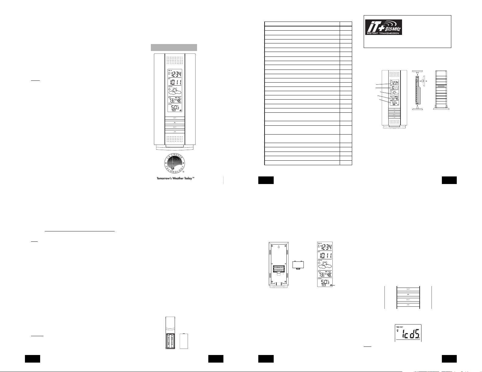
INVENTORY OF CONTENTS
1. The Wireless Weather Station/ (Figure 1).
2. One remote temperature sensor with mounting bracket (Figure 2).
3. Three each, 1/2" Philips screws.
4. Instruction manual and warranty card.
Figure 1
Time LCD
Date LCD
Forecast LCD
Indoor LCD
Outdoor LCD
ADDITIONAL EQUIPMENT (not included)
1. Two fresh AA 1.5V Alkaline batteries for the Wireless Weather
Station.
2. Two fresh AA 1.5V Alkaline batteries for the remote temperature
sensor.
3. One, Philips screwdriver for mounting.
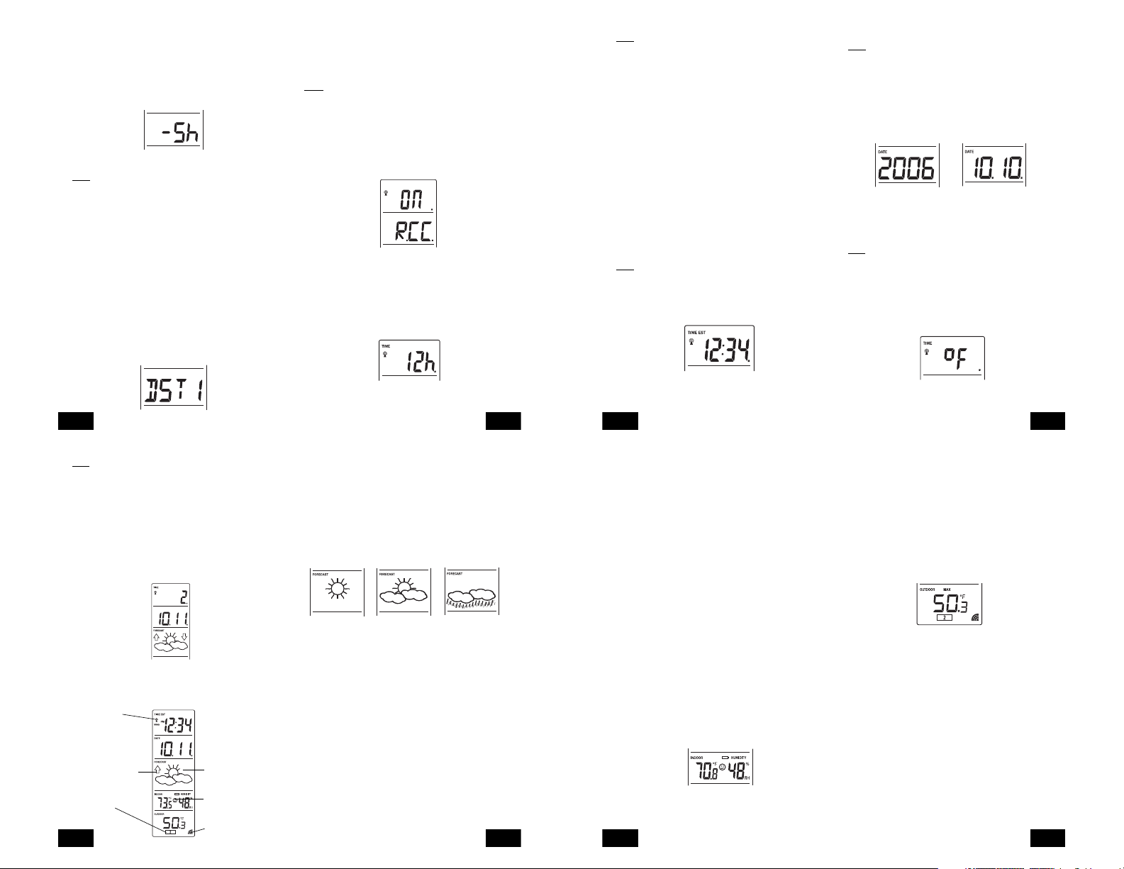
ABOUT WWVB (Radio Controlled Time)
The NIST (National Institute of Standards and Technology-Time and
Frequency Division) WWVB radio station is located in Ft. Collins,
Colorado, and transmits the exact time and date signal continuously
throughout the United States at 60 kHz. The signal can be received up
INSTANT TRANSMISSION
state-of-the-art new wireless
transmission technology, exclusively
designed and developed by LA
CROSSE TECHNOLOGY.
offers you can an immediate update
Mounting
Bracket
Figure 2
is the
TX29U-IT remote
temperature
sensor
P.3
GB
to 2,000 miles away through the internal antenna in the Weather Station.
However, due to the nature of the Earth’s Ionosphere, reception is
very limited during daylight hours. The Weather Station will search for
a signal every night when reception is best. The WWVB radio station
derives its signal from the NIST Atomic clock in Boulder, Colorado. A
team of atomic physicists is continually measuring every second, of
every day, to an accuracy of ten billionths of a second per day. These
physicists have created an international standard, measuring a second
as 9,192,631,770 vibrations of a Cesium-133 atom in a vacuum. For
more information on the atomic clock and WWVB please see the NIST
website at
http://www.boulder.nist.gov/timefreq/stations/wwvb.htm.
QUICK SET-UP GUIDE
Hint:
Use good quality Alkaline Batteries and avoid rechargeable
batteries.
1. Have the Wireless Weather Station and remote temperature sensor
3 to 5 feet apart.
2. Batteries should be out of both units for 10 minutes.
3. Place the batteries into the remote temperature sensor first then
into the Wireless Weather Station.
(All remote temperature sensors must be started before the Wireless
Weather Station)
4. DO NOT PRESS ANY BUTTONS FOR 15 MINUTES.
In this time the Wireless Weather Station and remote temperature
sensor will start to talk to each other and the display will show both the
indoor temperature and humidity, and an outdoor temperature. If the
Wireless Weather Station does not display both temperatures after the
15 minutes please retry the set up as stated above. After both indoor
and outdoor temperatures are displayed for 15 minutes you can place
your remote temperature sensor outdoor and set your time.
The remote temperature sensor should be placed in a dry, shaded
area. The temperature sensor has a range of 330 feet. Keep in mind
that the 330 feet is in open air with no obstructions and that radio
waves DO NOT curve around objects. Actual transmission range will
vary depending on what is in the path of the signal. Each obstruction
(roof, walls, floors, ceilings, thick trees, etc.) will effectively cut signal
range in half.
Example:
A Wireless Weather Station with a 330 feet range is mounted
on an interior wall, so that the signal has to pass through one interior
wall, one exterior wall, and across the 10 feet width of the room between
the 2 walls. The first wall will reduce the range to 165 feet, and the
second wall will reduce the range to 87 feet. Factoring in the 10 foot
room, this leaves a maximum of 77 feet of remaining signal range.
P.4
GB
This allowance is typically enough for a frame wall with non-metallic
siding; however certain materials can reduce range even further. Metal
siding, stucco, and some types of glass can reduce signal range by as
much as 3/4 or more, compared to the 1/2 reduction typical of most
obstructions. It is possible to receive a signal through these materials,
however maximum range will be much less due to their tendency to
absorb or reflect a much larger portion of the sensor’s signal.
To complete the set up of your Wireless Weather Station after the 15
minutes have passed please follow the steps that follow in the Detailed
Set-Up Guide.
DETAILED SET-UP GUIDE
I. BATTERY INSTALLATION
(When one temperature sensor is being used)
1. First, insert the batteries to the temperature sensor (see “A. Remote
Temperature Sensor” below).
2. Within 30 seconds of powering up the sensor, insert the batteries
to the Weather Station (see “B. Wireless Weather Station” below).
Once the batteries are in place, all segments of the LCD will light
up briefly. Following the indoor temperature and humidity, and the
time as 12:00 will be displayed. If they are not shown in LCD after
60 seconds, remove the batteries and wait for at least 60 seconds
before reinserting them. Once the indoor data is displayed user
may proceed to the next step.
3. After the batteries are inserted, the Weather Station will start
receiving data signal from the sensor. The outdoor temperature
should then be displayed on the Weather Station. If this does not
happen after 2 minutes, the batteries will need to be removed from
both units and reset from step 1 and the signal reception icon is no
longer shown.
A. REMOTE TEMPERATURE SENSOR
Battery Cover
SIZE AA LR6
SIZE AA LR6
1. Remove the mounting bracket. The bracket snaps on and off easily.
P.5
GB
2. Remove the battery cover, by sliding the cover down.
3. Observing the correct polarity install 2 AA batteries. The batteries
will fit tightly (to avoid start-up problems make sure they do not
spring free).
4. Replace the battery cover by sliding upwards. Be sure battery cover
is on securely.
B. WIRELESS WEATHER STATION
1. Remove the battery cover. To do this, insert a solid object in the
space provided at the lower-central position of the battery cover,
then push up and pull out on the battery cover.
2. Observe the correct polarity, and install 2 AA batteries.
3. Replace the battery cover.
Battery Cover
Sensor signal
reception icon*
* When the signal is successfully received by the Weather Station,
the icon will be switched on. (If not successful, the icon will not be
shown in LCD) So the user can easily see whether the last reception
was successful (icon on) or not (icon off). On the other hand, the
short blinking of the icon shows that a reception is being done now.
• If the signal reception is not successful on the first frequency
(915MHz) for 45 seconds, the frequency is changed to 920MHz
and the learning is tried another 45 seconds. If still not successful
the reception is tried for 45 seconds on 910MHz. This will also be
done for re-synchronization.
PROGRAM MODE
Programming Note: If 30 seconds is allowed to pass, or the CH button
is pressed during the programming mode, the unit will confirm/set the
last information entered-the display will stop flashing and return to
normal time-date readings. If you don’t leave the program mode during
the programming of sections III through XII, you can advance to step 4
P.6
GB
of the next program setting. If you do leave the program setting (or
want to program a specific setting) follow each instructional step to
program that setting.
I. PROGRAMMING SEQUENCE AND DEFAULT SETTINGS
The programming sequence and default (factory) settings are as
follows:
LCD Contrast 5
Time Zone -5 (Eastern)
Daylight Saving Time 1 (on)
Radio-controlled time receptionON
12/24-hour time 12
Time 12:00
Year 2006
Day and Month 1.1.
Snooze (this function not used) 10
Temperature Format ˚F
Forecast Sensitivity 2
Please note that while there is a snooze adjustment in the programming
this is an unused function as there is no alarm on the Wireless Weather
Station.
II. FUNCTION KEYS
The function keys are located on the front of the unit directly below the
LCD.
III. SETTING THE LCD CONTRAST
1. Press and hold the SET button for 5 seconds.
2. “LCD” will show in the time LCD and the number setting will flash.
Note:
There are 8 LCD contrast levels to choose from-”Lcd 0" is the
lightest, and “Lcd 7” is the darkest.
P.7
GB
Page 2
3. Press and release the IN button to select the level you desire.
4. Press and release the SET button to confirm and advance to the
Time Zone setting.
IV. TIME ZONE SETTING
1. Press and hold the SET button for 5 seconds.
2. “LCD” will show in the time LCD and the number setting will flash.
3. Press and release the SET button again.
4. The time zone will flash in the date LCD.
5. Press and release the IN button to select your time zone.
Note:
When a time zone for the U.S. is selected the corresponding
abbreviation will appear above the time (please see the table on the
next page). It is possible to select any time zone from -12 GMT to +12
GMT (for example to see the time in another country)
TIME ZONES
GMT 0
ALT Atlantic -4
EST Eastern -5
CST Central -6
MST Mountain -7
PST Pacific -8
ALA Alaska -9
HAW Hawaii -10
6. Press and release the SET button to confirm and advance to the
Daylight Saving Time setting.
V. DAYLIGHT SAVING TIME (DST) SETTING
1. Press and hold the SET button for 5 seconds.
2. “LCD” will show in the time LCD and the number setting will flash.
3. Press and release the SET button twice.
4. “DST” will appear in the date LCD and either “1” or “0” will flash.
5. Press and release the IN button to select DST on or off.
“DST 0” indicates that the feature is off and the WWVB will not change
times automatically. “DST 1” indicates that the feature is on and the
WWVB will change times automatically.
Note:
Some locations (Arizona and Hawaii) do not follow Daylight
Saving Time, and should select “DST 0.”
6. Press and release the SET button to confirm and advance to the
radio-controlled time on/off setting.
VI. RADIO-CONTROLLED TIME ON/OFF SETTING
1. Press and hold the SET button for 5 seconds.
2. “LCD” will show in the time LCD and the number setting will flash.
3. Press and release the SET button 3 times.
4. “RCC” will appear in the date LCD and “ON” or “OFF” will flash in
the time LCD.
5. Press and release the IN button to select radio-controlled time on
or off.
6. Press and release the SET button to confirm and advance to the
12/24-hour time setting.
VII. 12 OR 24 HOUR TIME SETTING
1. Press and hold the SET button for 5 seconds.
2. “LCD” will show in the time LCD and the number setting will flash.
3. Press and release the SET button 4 times.
4. “12h” or “24h” will flash in the time LCD.
Note:
When in the 12-hour format “P.M.” will appear to the left of the
hour in the time LCD between the hours of noon and midnight.
6. Press and release the SET button to confirm and advance to the
time setting.
VIII. TIME SETTING
There are two methods by which the time and date can be set:
A. Automatically via WWVB reception, or
B. Manually.
A. WWVB (Remote Control Time)
This method requires you to do nothing, except wait for the signal to be
received, and to select a time zone. Reception usually takes
approximately 10 minutes during optimal conditions. The best condition
for reception is at night, between midnight and 6:00 am-when there is
less atmospheric interference. To keep your time as accurate as
possible, Wireless Weather Station conducts a WWVB search every
night between these hours, and overrides any manually set time. The
WWVB tower icon (appearing in the TIME LCD) will flash when a signalsearch is in progress and a signal is being received, and will remain
steady when the signal has been received. If the WWVB time has not
been received after 10 minutes of battery installation, you may manually
set the time or leave the time function alone (reception will occur
regardless). After a successful reception, no more reception attempt
would be made until the following day.
B. MANUAL TIME SETTING
Note:
When in the 12-hour format “P.M.” will appear to the left of the
hour in the time LCD between the hours of noon and midnight.
1. Press and hold the SET button for 5 seconds.
2. “LCD” will show in the time LCD and the number setting will flash.
3. Press and release the SET button 5 times.
4. The time will flash in the time LCD.
IX. SETTING THE YEAR, DAY AND MONTH
Note:
Reception of the WWVB signal will also set the date and day.
The reception of the signal will override any programmed date and
day.
1. Press and hold the SET button for 5 seconds.
2. “LCD” will show in the time LCD and the number setting will flash.
3. Press and release the SET button 6 times.
4. The year will flash in the date LCD.
5. Press and release the IN button to advance the year.
6. Press and release the SET button to confirm and advance to the
day/month setting.
7. The day and month will flash in the date LCD.
8. Press and release the IN button to advance the month.
9. Press and release the OUT button to advance the day.
10.Press and release the SET button to confirm and advance to the
snooze setting.
X. SETTING THE SNOOZE
Note:
This is an unused function of the Wireless Weather Station and
should be disregarded. The setting has no bearing on the operation.
Please press and release the SET button to advance to select the
temperature format.
XI. SELECTING ˚F OR ˚C
1. Press and hold the SET button for 5 seconds.
2. “LCD” will show in the time LCD and the number setting will flash.
3. Press and release the SET button 9 times.
4. Either “˚F” or “˚C” will flash in the time LCD.
P.8
GB
XII. SETTING THE FORECAST SENSITIVITY
Note:
The forecast sensitivity can be adjusted to allow for areas that
have a higher or lower sensitivity to changing air pressure (for example
coastal areas have more pressure change than areas such as southern
Arizona).
The numbers correspond to the amount of air pressure change
necessary to trigger a change in the forecast icon. Areas that tend to
have more air pressure change would set the sensitivity to 3, while
areas that experience lower than normal air pressure change would
set the sensitivity to 1.
1. Press and hold the SET button for 5 seconds.
2. “LCD” will show in the time LCD and the number setting will flash.
3. Press and release the SET button 10 times.
4. Either “1”, “2” or “3” will flash in the time LCD.
5. Press and release the IN button to select the forecast sensitivity
6. Press and release the SET button to confirm the forecast sensitivity
and complete the programming.
FEATURES OF THE WS-7017U-IT
WWVB Tower Icon
(indicates time reception)
Weather Tendency Arrow
Remote Sensor
Number (Up to 3
Total)
P.12
GB
Forecast Icon
Comfort Level
Indicator
Satellite Icon
(indicates outdoor
transmission)
5. Press and release the IN button to select 12 or 24-hour time format.
P.9
GB
I. WEATHER FORECAST
The weather forecasting feature is estimated to be 75% accurate and
is for the upcoming 12 to 24 hours. The weather forecast is based
solely upon the change of air pressure over time. The WS-7017U-IT
averages past air-pressure readings to provide an accurate forecastcreating a necessity to disregard all weather forecasting for 12-24 hours
after the unit has been set-up, reset, or moved from one altitude to
another (i.e. from one floor of a building to another floor). In areas
where the weather is not largely affected by the change of air pressure,
the sensitivity setting should be set to 1.
A. WEATHER ICONS
There are 3 possible weather icons that will be displayed in the
FORECAST LCD:
Sunny-indicates that the weather is expected to improve (not that the
weather will be sunny).
Sun with Clouds-indicates that the weather is expected to be fair (not
that the weather will be sunny with clouds).
Clouds with Rain-indicates that the weather is expected to get worse
(not that the weather will be rainy).
These icons indicate the expected weather change in the next 12 to
24 hours. The icon does not give an exact prediction of the weather,
however it should be viewed as a generalization of the expected weather
change (for example a “sunny” icon indicates the weather is expected
to improve).
The weather icons change when the unit detects a change in air
pressure. The icons change in order, from “sunny” to “partly sunny” to
“cloudy” or the reverse. It will not change from “sunny” directly to “rainy”,
although it is possible for the change to occur quickly. If the symbols
do not change then the weather has not changed, or the change has
been slow and gradual.
B. WEATHER TENDENCY ARROWS
Other possible displays in the FORECAST LCD are 2 weather tendency
arrows, one that points up (on the left side of the LCD) and one that
points down (on the right side of the LCD). These arrows reflect current
changes in the air pressure. An arrow pointing up indicates that the
P.13
GB
5. Press and release the IN button to advance the hours.
6. Press and release the OUT button to advance the minutes.
7. Press and release the SET button to confirm and advance to the
year setting.
P.10
GB
air pressure is increasing and the weather is expected to improve or
remain good, an arrow pointing down indicates that the air pressure is
decreasing and the weather is expected to become worse or remain
poor.
II. INDOOR TEMPERATURE, HUMIDITY, AND COMFORT LEVEL
INDICATOR
The current indoor temperature (viewed on the left) and relative humidity
(viewed on the right) are displayed in the INDOOR LCD. The comfort
level indicator is located at the center of the INDOOR LCD. The indicator
will display a happy face icon when the temperature is between 68˚F
and 79˚F (20˚C and 25.9˚C), and the humidity is between 45% and
65%. A sad face icon will be displayed when the temperature and
humidity are outside the mentioned ranges.
III. OUTDOOR TEMPERATURE
The temperature received from the remote temperature sensor is viewed
in the OUTDOOR LCD. When there is more than one remote
temperature sensor unit in operation, a “boxed” number will appear to
the right of the temperature. This indicates which remote temperature
sensor unit (1, 2, or 3) is currently displaying its data in the OUTDOOR
LCD. (This feature is explained in further detail in section V-Adding
Remote Temperature Sensors).
IV. MINIMUM AND MAXIMUM TEMPERATURE RECORDS
The WS-7017U-IT keeps a record of the MINIMUM and MAXIMUM
temperature, and the time and date of their occurrence-for both the
indoor and outdoor modes.
A. VIEWING THE INDOOR TEMPERATURE AND HUMIDITY
RECORDS
1. Press the IN button once. “MIN” appears above the indoor
temperature and the LCD will flash, indicating that the minimum
temperature and humidity, and the time and date of occurrence of
the indoor temperature are displayed. The minimum records will
display for 30 seconds before returning to the normal display mode.
2. Press the IN button again (once while “MIN” is still displayed, twice
otherwise). “MAX” appears above the indoor temperature and the
LCD will flash, indicating that the maximum temperature and
humidity, and the time and date of occurrence of the indoor
P.14
GB
5. Press and release the IN button to select the temperature format.
6. Press and release the SET button to confirm and advance to the
forecast sensitivity setting.
temperature are displayed.
3. While “MAX” is still displayed press the IN button again to return to
the current data display. Or you can wait 30 seconds, during either
the minimum or the maximum readings, and the unit will
automatically return to current data readings.
B. VIEWING THE OUTDOOR TEMPERATURE RECORDS
1. Press the OUT button once. “MIN” appears above the outdoor
temperature and the LCD will flash, indicating that the minimum
temperature, and the time and date of occurrence are displayed.
The minimum records will display for 30 seconds before returning
to the normal display mode.
2. Press the OUT button again (once while “MIN” is still displayed,
twice otherwise). “MAX” appears above the outdoor temperature
and the LCD will flash, indicating that the maximum temperature
and the time and date of occurrence are displayed.
3. While “MAX” is still displayed press the OUT button again to return
to the current data display. Or you can wait 30 seconds, during
either the minimum or the maximum readings, and the unit will
automatically return to current data readings.
C. RESETTING THE MIMIMUM AND MAXIMUM RECORDS
1. All the indoor records (minimum and maximum) will be reset after
the IN button is pressed and held for 5 seconds.
2. All the outdoor records (minimum and maximum) will be reset after
the OUT button is pressed and held for 5 seconds.
V. ADDING REMOTE TEMPERATURE SENSORS (OPTIONAL)
The WS-7017U-IT is able to receive signals from 2 additional
temperature sensors. The following are instructions for the set-up of
temperature sensor units with the WS-7017U-IT. These extra sensors
can be purchased through the same dealer as this unit.
1. Remove all the batteries from the receiver and sensor(s) and wait
60 seconds. During these 60 seconds, press any button 20 times
to discharge any excess power.
2. Insert the batteries to the first temperature sensor.
3. Within 30 seconds of powering up the first sensor, insert the
batteries to the Weather Station. Once the batteries are in place,
all segments of the LCD will light up briefly. Following this the indoor
temperature and indoor humidity, time as 12:00, calendar, and
P.11
P.15
GB
GB
Page 3
weather icons will be displayed. If they are not shown in LCD after
60 seconds, remove the batteries and wait for at least 60 seconds
before reinserting them.
4. The outdoor temperature from the first sensor (channel 1) should
then be displayed on the Weather Station. If this does not happen
and the signal reception icon is not shown, after 2 minutes, the
batteries will need to be removed from both units and reset from
step 1.
5. Insert the batteries to the second sensor as soon as the outdoor
temperature readings from the first sensor are displayed on the
Weather station.
NOTE:
You must insert the batteries into the second sensor within 10
seconds of reception of the first sensor.
6. The outdoor temperature from the second sensor and the “channel
2” icon should then be displayed on the Weather Station. If this
does not happen after 2 minute, the batteries will need to be removed
from all the units and reset from step 1.
7. Insert the batteries to the third sensor as soon as the “channel 2”
icon and outdoor data are displayed on the Weather Station. Then
within 2 minutes, the channel 3 outdoor data from the third sensor
will be displayed and the channel icon will shift back to “1” once the
third sensor is successfully received. If this is not happen, user shall
restart the setting up from step 1.
NOTE:
You must insert the batteries into the third sensor within 10
seconds of reception of the second sensor.
IMPORTANT:
Transmission problems will arise if the setting for multiple
sensors is not followed as described above. Should transmission
problems occur, it is necessary to remove the batteries from all units
and start again the set-up from step 1.
VI.VIEWING AND OPERATING WITH MULTIPLE REMOTE
TEMPERATURE SENSOR UNITS
1. To view the temperature of a different remote temperature sensor
unit, press and release the CH button. A shift from one “boxed”
number to the next should be observed in the OUTDOOR LCD.
2. To view the Minimum/Maximum temperature: first select which
remote temperature sensor to read data from (indicated by the
“boxed” number), then press the OUT button. Pressing this button
once will display the minimum temperature, and the date and time
the data was recorded. Pressing this button a second time (while
“MIN” is still displayed, otherwise press the button twice) will display
the same data for the maximum recordings.
P.16
GB
6. To reset the Minimum/Maximum readings, it is necessary to select
which remote temperature sensor you wish to reset. Press and
hold the OUT button for 5 seconds, the records for the selected
remote temperature sensor unit will be reset.
MOUNTING
Note:
Before permanently mounting ensure that the Wireless Weather
Station is able to receive WWVB signals from the desired location.
Also, extreme and sudden changes in temperature will decrease the
accuracy of the Wireless Weather Station, and changes in elevation
will result with inaccurate weather forecasting for the next 12 to 24
hours. These changes will require a 12 to 24 hour wait before obtaining
reliable data. To achieve a true temperature reading, avoid mounting
where direct sunlight can reach the remote temperature sensor or
Wireless Weather Station. While the remote temperature sensor is
weather proof, avoid submersion in water or snow. We recommend
that you mount the remote temperature sensor on an outside Northfacing wall. The sending range is 330ft-obstacles such as walls,
concrete, and large metal objects can reduce the range. Place both
units in their desired location, and wait approximately 15 minutes before
permanently mounting to ensure that there is proper reception. The
Wireless Weather Station should display a temperature in the
OUTDOOR LCD within 4 minutes of setting up.
I. THE REMOTE TEMPERATURE SENSOR
The remote temperature sensor should be mounted with the use of
screws.
A. MOUNTING WITH SCREWS
1. Remove the mounting bracket from the remote temperature sensor.
2. Place the mounting bracket over the desired location.
3. Through the three screw holes of the bracket, mark the mounting
surface with a pencil.
4. Screw mounting bracket onto the mounting surface. Ensure that
P.17
GB
the screws are flush with the bracket.
5. Insert the remote temperature sensor into the bracket.
II. THE WIRELESS WEATHER STATION
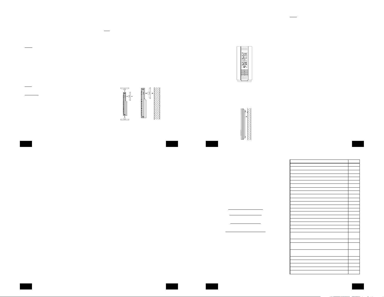
The Wireless Weather Station can be mounted in two ways:
• with the table stand or,
• on the wall with the use of a wall hanging screw (not included).
A. USING THE TABLE STAND
The Wireless Weather Station comes with the table stand already
mounted. If you wish to use the table-stand all that is required is to
place the Wireless Weather Station in an appropriate location.
B. WALL MOUNTING
1. Remove the table-stand. To do this, pull down on the stand from
the rear and rotate forward.
2. Fix a screw (not included) into the desired wall, leaving approximately
3/16 of an inch (5mm) extended from the wall.
3. Place the Wireless Weather Station onto the screw using the hanging
hole on the backside.
4. Gently pull the Wireless Weather Station down to lock the screw
into place.
P.18
GB
TROUBLESHOOTING
NOTE:
For problems not solved, please contact La Crosse Technology.
Problem: No reception of WWVB time signal.
Solution:
1. Wait overnight for signal.
2. Be sure Weather Station is at least 6 feet from any electrical devices,
such as televisions, computers, or other radio-controlled clocks.
3. Remove batteries for five minutes, reinsert and leave the unit alone
overnight without pressing buttons.
4. If there are still problems, contact La Crosse Technology
Problem: Hour is incorrect (minute and date are correct)
Solution:
Be sure correct time zone and daylight saving time settings are selected.
Problem: The LCD is faint
Solution:
1. Set the LCD contrast to a higher number
2. Replace batteries
Problem: No outdoor temperature is displayed.
Solution:
1. Remove all batteries, reinsert into sender first, then display.
2. Place remote sender closer to display.
3. Be sure all batteries are fresh.
4. Place Temperature Sensor and Weather Station in position so the
straight-line signal is not passing through more than two or three
walls.
Problem:
Temperatures do not match if units are placed next to each other.
Solution:
Each temperature sensor is manufactured to be accurate to within 2˚F
plus or minus and under normal conditions, so two sensors could be
as much as 4˚F different. However, the difference can be exaggerated
further because the sensors are designed for different working
environments. The indoor sensor is less responsive to ambient air
currents because of the shielding effect of the display’s case. In addition,
the case can act as a heat sink to absorb and store heat from external
sources (i.e. handling of the case or radiant heat). Also, the much
greater range of the outdoor temperature sensor requires a different
calibration curve than the indoor range. Error is usually greater at the
extreme ends of a range, making it harder to compare different ranges
with different curves. Under non-laboratory conditions, it is difficult to
compensate for the above factors and obtain an accurate comparison.
P.19
GB
MAINTENANCE AND CARE INSTRUCTIONS
• Extreme temperatures, vibration, and shock should be avoided to
prevent damage to the units.
• Clean displays and units with a soft, damp cloth. Do not use solvents
or scouring agents; they may mark the displays and casings.
• Do not submerge in water.
• Immediately remove all low powered batteries to avoid leakage and
damage.
• Opening the casings invalidates the warranty. Do not try to repair
the unit. Contact La Crosse Technology for repairs.
SPECIFICATIONS
Temperature measuring range:
Indoor: 14.1˚F to 139.8˚F with 0.2˚F resolution.
Outdoor: -39.8˚F to 139.8˚F with 0.2˚F resolution.
Indoor relative humidity measuring range:1% to 99% with 1% resolution.
Indoor Temperature checking interval: Every 10 seconds.
Indoor Humidity checking interval: Every 15 seconds.
Outdoor Temperature checking interval
(Remote Temperature Sensor): Every 4 seconds
Outdoor Temperature reception
(Weather Station): Every 4 seconds.
Transmission Range: 330 feet (in open space).
Power Supply:
Weather Station: 2 x AA, IEC LR6, 1.5V.
Remote Temperature Sensor: 2 x AA, IEC LR6, 1.5V.
Battery life cycle: Approximately 24 months.
Recommended battery type: Alkaline.
Dimensions (H x L x W)
Weather Station (without stand): 8.75" x 4" x 1.5"
Remote Temperature Sensor: 5.05" x 1.50" x 0.83"
WARRANTY INFORMATION
La Crosse Technology, Ltd provides a 1-year limited warranty on this
product against manufacturing defects in materials and workmanship.
This limited warranty begins on the original date of purchase, is valid
GB
(-9.9˚C to 59.9˚C with 0.1˚C resolution)
“OFL” displayed if outside this range.
(-39.9˚C to 59.9˚C with 0.1˚C resolution).
“OFL” displayed if outside this range.
P.20
(Display “- -” if temperature is
OL.F; display “- -” if < 1% and
“99%” if > 99%)
(222 x 102 x 38 mm)
(128.3 x 38.2 x 21.2 mm)
only on products purchased and used in North America and only to
the original purchaser of this product. To receive warranty service, the
purchaser must contact La Crosse Technology, Ltd for problem
determination and service procedures. Warranty service can only be
performed by a La Crosse Technology, Ltd authorized service center.
The original dated bill of sale must be presented upon request as proof
of purchase to La Crosse Technology, Ltd or La Crosse Technology,
Ltd’s authorized service center.
La Crosse Technology, Ltd will repair or replace this product, at our
option and at no charge as stipulated herein, with new or reconditioned
parts or products if found to be defective during the limited warranty
period specified above. All replaced parts and products become the
property of La Crosse Technology, Ltd and must be returned to La
Crosse Technology, Ltd. Replacement parts and products assume
the remaining original warranty, or ninety (90) days, whichever is longer.
La Crosse Technology, Ltd will pay all expenses for labor and materials
for all repairs covered by this warranty. If necessary repairs are not
covered by this warranty, or if a product is examined which is not in
need or repair, you will be charged for the repairs or examination. The
owner must pay any shipping charges incurred in getting your La Crosse
Technology, Ltd product to a La Crosse Technology, Ltd authorized
service center. La Crosse Technology, Ltd will pay ground return
shipping charges to the owner of the product to a USA address only.
Your La Crosse Technology, Ltd warranty covers all defects in material
and workmanship with the following specified exceptions: (1) damage
caused by accident, unreasonable use or neglect (including the lack
of reasonable and necessary maintenance); (2) damage occurring
during shipment (claims must be presented to the carrier); (3) damage
to, or deterioration of, any accessory or decorative surface; (4) damage
resulting from failure to follow instructions contained in your owner’s
manual; (5) damage resulting from the performance of repairs or
alterations by someone other than an authorized La Crosse Technology,
Ltd authorized service center; (6) units used for other than home use
(7) applications and uses that this product was not intended or (8) the
products inability to receive a signal due to any source of interference..
This warranty covers only actual defects within the product itself, and
does not cover the cost of installation or removal from a fixed installation,
normal set-up or adjustments, claims based on misrepresentation by
the seller or performance variations resulting from installation-related
circumstances.
LA CROSSE TECHNOLOGY, LTD WILL NOT ASSUME LIABILITY
FOR INCIDENTAL, CONSEQUENTIAL, PUNITIVE, OR OTHER
SIMILAR DAMAGES ASSOCIATED WITH THE OPERATION OR
P.21
GB
MALFUNCTION OF THIS PRODUCT. THIS PRODUCT IS NOT TO
BE USED FOR MEDICAL PURPOSES OR FOR PUBLIC
INFORMATION. THIS PRODUCT IS NOT A TOY. KEEP OUT OF
CHILDREN’S REACH.
This warranty gives you specific legal rights. You may also have other
rights specific to your State. Some States do no allow the exclusion of
consequential or incidental damages therefore the above exclusion of
limitation may not apply to you.
For warranty work, technical support, or information contact:
La Crosse Technology
2809 Losey Blvd. S.
La Crosse, WI 54601
Phone: 608.782.1610
Fax: 608.796.1020
e-mail:
support@lacrossetechnology.com
(warranty work)
sales@lacrossetechnology.com
(information on other products)
web:
www.lacrossetechnology.com
Questions? Instructions? Please visit:
www.lacrossetechnology.com/7017it
All rights reserved. This handbook must not be reproduced in any
form, even in excerpts, or duplicated or processed using electronic,
mechanical or chemical procedures without written permission of the
publisher.
This handbook may contain mistakes and printing errors. The
information in this handbook is regularly checked and corrections made
in the next issue. We accept no liability for technical mistakes or printing
errors, or their consequences.
All trademarks and patents are acknowledged.
P.22
GB
TABLE DES MATIÈRES
Sujet Page
Inventaire/ Équipement supplémentaire 24
A propos du WWVB 24
Guide de paramétrage rapide 25
Guide de paramétrage détaillé
Installation des Piles 26
Mode de programmation
Séquence de programmation et réglages par défaut 28
Touches de fonction 28
Contraste de l’écran LCD 28
Fuseau horaire 29
Heure d’été 29
Heure radiocommandée 30
Format 12/24 H 30
Heure 31
Jour date et année 32
Fonction “Snooze” 32
Format d’affichage de la température 32
Sensibilité des prévisions météo 33
Fonctionnalités
Icônes de prévision météo et flèches de tendance 34
Température et humidité intérieures & Indicateur du
confort intérieur 35
Températures extérieures 35
Relevés minimum & maximum
(intérieur, extérieur & remise à zéro) 36
Émetteurs télécommandés supplémentaires
(Installation, Affichage & Fonctionnement) 37
Fixation 38
Dépistage des pannes 40
Entretien & soin 41
Caractéristiques techniques 42
Informations sur la garantie 42
P.23
F
Page 4

Le produit vous offre:
INSTANT TRANSMISSION
les 4 secondes !) de toutes les données extérieures relevées par
les capteurs: suivez les variations climatiques en temps réel!
INVENTAIRE
1. La station météo (Fig. 1).
2. Un capteur thermique distant avec support de fixation (Fig. 2).
3. Trois vis cruciformes, 1/2".
4. Manuel d’instructions et fiche de garantie.
Fig 1
Ecran LCD Heure
Ecran LCD Date
Ecran LCD
Prévisions
Ecran LCD
Intérieur
Ecran LCD
Extérieur
ÉQUIPEMENT SUPPLÉMENTAIRE (non-fourni)
1. Deux piles neuves 1,5V de type AA.
2. Deux piles neuves 1,5V de type AA.
3. Un tournevis à lame cruciforme.
4. Un tournevis à lame plate.
A PROPOS DU WWVB (Heure radiocommandée)
L’émetteur radio WWVB de la NIST (National Institute of Standards
and Technology-Time and Frequency Division) WWVB est situé à Ft.
Collins dans le Colorado et émet un signal horaire exact en continu sur
60 kHz à travers les États-Unis. Le signal peut être réceptionné dans
un rayon de 3 200 km à l’aide de l’antenne incorporée à la station
P.24
F
INSTANT TRANSMISSION
nouvelle technologie de
transmission sans fil de pointe
conçue et développée en exclusivité
par LA CROSSE TECHNOLOGY.
assure la mise à jour immédiate (toutes
Support
Fig 2
est la
TX29U-IT
capteur de
température
météo. Cependant, cette réception est très restreinte pendant la
journée, à cause des effets de l’ionosphère terrienne. Chaque nuit,
lorsque les conditions de réception sont optimales, la station météo
recherchera le signal. L’émetteur radio WWVB prend son signal à partir
de l’horloge atomique de la NIST à Boulder, Colorado. Une équipe de
physiciens en atomique mesure en continu chaque seconde de chaque
jour à une exactitude de dix-milliardièmes de seconde par jour. Ces
physiciens ont établi la norme internationale pour une seconde, comme
étant 9 192 631 770 vibrations d’un atome de Césium-133 dans un
vacuum.
Pour plus d’informations sur le WWVB et l’horloge atomique, visitez le
site web du NIST
htm.
GUIDE DE PARAMÉTRAGE RAPIDE
Conseil:
rechargeables.
1. Placez le capteur ther mique distant à 1m - 1m 50 de la station
météo intérieure.
2. Les piles doivent être retirées des deux unités pendant 10 minutes.
3. Insérez en premier les piles du capteur thermique distant,
puis celles de la station météo intérieure.
(Toutes les unités distantes extérieures doivent être initialisées avant
d’initialiser la station intérieure)
4. N’APPUYEZ SUR AUCUNE TOUCHE PENDANT 15 MINUTES.
Pendant ce temps, la station météo intérieure et le capteur thermique
commenceront à ‘dialoguer’, la station affichant la température et
l’humidité intérieures une température extérieure. Si la station météo
n’affiche pas toutes ces informations dans les 15 minutes, répétez la
procédure de paramétrage détaillée ci-dessus. Lorsque les
informations ont été affichées pendant 15 minutes, vous pouvez
installer votre capteur à l’extérieur et régler l’heure.
Placer le capteur dans un lieu approprié. L’appareil devrait être installé
dans un endroit sûr et plat dans lequel il peut recueillir la pluie
correctement sans obstruction. Le capteur a une portée de 100 m
(330 pieds). Ne pas oublier que cette portée est calculée en plein air
sans obstruction et que les ondes radio NE CONTOURNENT PAS les
objets. Le rayon de transmission réel dépend de ce qui compose le
parcours du signal. Chaque obstruction (toit, murs, planchers, plafonds,
arbres épais, etc) diminue en effet cette distance de moitié.
Exemple:
(330 pieds) est monté sur un mur intérieur de façon à ce que le signal
doive traverser un mur intérieur, un mur extérieur et les 3,3m (10 pieds)
http://www.boulder.nist.gov/timefreq/stations/wwvb.
Utilisez des piles alcalines de marque et évitez les piles
Le réceptacle du capteur sans fil d’une portée de 100m
P.25
de la largeur de la pièce entre les deux murs. Le premier mur réduit la
portée à (165 pieds), et le second mur la réduit à 29m (87 pieds).
Ajoutant à cela les 3,3m (10 pieds) de la largeur de la pièce, il reste
26m (77pieds) de portée au signal.
Cette distance suffit généralement pour un mur sans armature
métallique ; cependant certains matériaux peuvent la réduire davantage.
Armature métallique, stuc et certains types de verre peuvent réduire la
portée du signal de 3/4 ou plus, comparé à une réduction de 1/2 typique
de la plupart des obstructions. Il est possible de recevoir un signal à
travers ces matériaux, cependant la portée maximum sera bien
inférieure en raison de leur tendance à absorber ou réfléchir une portion
beaucoup plus importante du signal du capteur.
Pour terminer l’installation de votre station météo sans fil une fois les
15 minutes écoulées, référez-vous au Guide de paramétrage détaillé
ci-après.
GUIDE DE PARAMÉTRAGE DETAILLE
I. INSTALLATION DES PILES
(Quand on utilise un capteur de température)
1. Commencer par installer les piles du capteur de température (voir
“A. Capteur de température” ci-dessous).
2. Dans les 30 secondes qui suivent la mise sous tension du capteur,
installer les piles de la station de température (voir “
sans fil” ci-dessous). Une fois que les piles sont en place, tous les
segments du LCD s’affichent brièvement. Ensuite, la température
intérieure et l’heure (12:00) s’affichent. Si elles ne s’affichent pas
sur le LCD dans les 60 secondes qui suivent, retirer les piles et
attendre au moins 60 secondes avant de les remettre en place.
Une fois que les données intérieures sont affichées, passer à l’étape
suivante.
3. Quand les piles sont en place, la station météo commence à recevoir
le signal des données du capteur. La température extérieure devrait
s’afficher sur la station météo. Si elles ne s’affichent pas dans les 2
minutes, retirer les piles de tous les appareils et recommencer à
partir de l’étape 1 ; l’icône de réception du signal n’est plus affichée.
A. Capteur de température
1. Retirez le support de fixation. Le support se détache et s’attache
facilement.
2. Retirez le couvercle du compartiment à piles en le faisant glisser
vers le bas.
3. Installez 2 piles de type AA en respectant la polarité. Les piles
s’enclenchent fermement (afin d’éviter tout problème au démarrage,
P.26
F
F
B.Station météo
vérifiez qu’elles restent bien en place).
4. Remplacez le couvercle du compartiment en le faisant glisser vers
le haut. Assurez-vous de sa bonne fermeture.
Couvercle du
compartiment
des piles
SIZE AA LR6
SIZE AA LR6
B. STATION MÉTÉO INTÉRIEURE
1. Retirez le couvercle du compartiment à piles. Pour ce faire, insérez
un objet rigide dans la fente entre le bas du couvercle et le boîtier,
puis soulevez en le tirant vers l’extérieur.
2. Insérez 2 piles de type AA en respectant la polarité.
3. Remettez le couvercle du compartiment à piles.
Couvercle du
compartiment
des piles
Icône de
réception du
signal du
* Quand la station météo reçoit le signal, l’icône s’allume. (Sinon,
l’icône n’apparaît pas sur le LCD). De cette façon, l’utilisateur peut
voir facilement si la dernière réception a réussi (icône affiché) ou
non (icône absent). Par ailleurs, un icône qui clignote rapidement
indique qu’une réception est en cours.
• En cas de non réception du signal sur la première fréquence (915
MHz) dans les 45 secondes, la fréquence passe à 920MHz et un
nouvel essai d’apprentissage est effectué pendant 45 secondes.
En cas d’insuccès, un nouvel essai de réception est effectué
pendant 45 secondes sur 910MHz. Ces essais sont aussi effectués
pour re-synchronization.
capteur*
P.27
F
MODE PROGRAMMATION
Remarque sur la programmation:
écoulées, ou si la touche CH est pressée en mode Programmation,
l’appareil validera les dernières informations entrées, l’écran arrêtera
de clignoter et reviendra à l’affichage normal de l’heure et de la date.
Si vous ne quittez pas le mode Programmation pendant la
programmation des sections III à XII, vous pouvez passer à l’étape 4
de la programmation suivante. Si vous quittez le mode Programmation
(ou si vous désirez effectuer une programmation spécifique), suivez
les étapes des instructions propres à cette programmation.
I. SÉQUENCE DE PROGRAMMATION ET RÉGLAGES PAR
DÉFAUT
La séquence de programmation et les réglages par défaut (usine) sont :
Contraste de l’écran LCD 5
Fuseau horaire -5 (Est)
Heure d’été 1 (on/activée)
Réception du signal horaire ON (activé)
Format 12/24 H 12
Heure 12:00
Année 2006
Jour et mois 1.1.
“Snooze” (fonction non-disponible) 10
Format d’affichage de la température ˚F
Sensibilité des prévisions 2
II. TOUCHES DE FONCTION
Les commandes de fonction sont situées sur le devant de l’appareil
directement au-dessous du LCD.
III. CONTRASTE DE L’ÉCRAN LCD
1. Appuyez sur la touche SET pendant 5 secondes.
2. “LCD” s’affiche à la section Heure de l’écran LCD et le chiffre
clignote.
P.28
F
Après que 30 secondes se sont
Remarque:
Huit niveaux de contraste de l’écran LCD sont
programmables- du plus clair “Lcd 0” au plus foncé “Lcd 7”.
3. Appuyez sur la touche IN pour sélectionner le niveau de contraste
désiré.
4. Appuyez sur la touche SET pour confirmer et passer en mode
réglage du Fuseau Horaire.
IV. FUSEAU HORAIRE
1. Appuyez sur la touche SET pendant 5 secondes.
2. “LCD” s’affiche à la section HEURE de l’écran LCD et le chiffre
clignote.
3. Appuyez de nouveau sur la touche SET.
4. Le fuseau horaire clignote à la section Date de l’écran LCD.
5. Appuyez sur la touche IN pour sélectionner votre fuseau horaire.
Remarque:
Lorsqu’un fuseau horaire des E.U. est sélectionné,
l’abréviation correspondant s’affiche au-dessus de l’heure (voir la table
page suivante). Tous les fuseaux horaires de -12 GMT à +12 GMT
peuvent être sélectionnés (par exemple, pour connaître l’heure dans
un pays étranger)
FUSEAUX HORAIRES
GMT 0
ALT Atlantique -4
EST Est -5
CST Central -6
MST Montagne -7
PST Pacifique -8
ALA Alaska -9
HAW Hawaii -10
6. Appuyez sur la touche SET pour confirmer et passer à la
programmation de l’Heure d’Été.
V. HEURE D’ÉTÉ (DST)
1. Appuyez sur la touche SET pendant 5 secondes.
2. “LCD” s’affiche à la section HEURE de l’écran LCD et le chiffre
clignote.
P.29
3. Appuyez deux fois sur la touche SET.
4. “DST” s’affiche à la section Date de l’écran LCD et soit “1” soit “0”
clignote.
5. Appuyez sur la touche IN pour activer ou désactiver la fonction DST.
“DST 0” indique que cette fonction est désactivée et le centre WWVB
ne changera pas l’heure automatiquement. “DST 1” indique que la
fonction est activée et que le centre WWVB basculera l’heure
automatiquement en heure d’été.
Remarque:
Quelques régions (dont l’Arizona et Hawaii) n’appliquent
pas l’heure d’été. Les habitants de ces régions devront sélectionner
“DST 0.”
6. Appuyez sur la touche SET pour confirmer et passer à la
programmation de l’Heure radiocommandée.
VI. HEURE RADIOCOMMANDÉE ACTIVÉE/DÉSACTIVÉE
1. Appuyez sur la touche SET pendant 5 secondes.
2. “LCD” s’affiche à la section Heure de l’écran LCD et le chiffre
clignote.
3. Appuyez trois fois sur la touche SET.
4. “RCC” s’affiche à la section Date de l’écran LCD et “ON” ou “OFF”
clignote à la section Heure de l’écran LCD.
5. Appuyez sur la touche IN pour activer ou désactiver l’heure
radiocommandée
6. Appuyez sur la touche SET pour confirmer et passer à la
programmation du format d’affichage 12/24H.
VII.FORMAT 12/ 24 H
1. Appuyez sur la touche SET pendant 5 secondes.
2. “LCD” s’affiche à la section Heure de l’écran LCD et le chiffre
clignote.
F
P.30
F
3. Appuyez 4 fois sur la touche SET.
4. “12h” ou “24h” clignote à la section Heure de l’écran LCD.
5. Appuyez sur la touche IN pour sélectionner le format 12H ou 24H.
Remarque:
En format 12H et entre midi et minuit, “P.M.” s’affiche à
gauche de l’heure à la section Heure de l’écran LCD.
6. Appuyez sur la touche SET pour confirmer et passer à la
programmation de l’heure.
VIII. HEURE
L’heure et la date peuvent être programmées de deux façons :
A. Automatiquement par la réception WWVB, ou
B. Manuellement.
A. WWVB (Heure radiocommandée)
Cette méthode ne demande aucune intervention de votre part, en
dehors d’attendre la réception du signal et sélectionner le fuseau
horaire. Sous les conditions optimales, la réception prend normalement
10 minutes. Les conditions optimales se présentent la nuit entre minuit
et 06H00, la période d’interférences atmosphériques minimales. Pour
assurer l’exactitude de l’heure, la station météo recherche le signal
WWVB chaque nuit entre ces heures et neutralise tout réglage manuel.
L’icône WWVB en forme de tour (affichée à la section HEURE de l’écran
LCD) clignote pendant la recherche et la réception et reste allumée
lorsque la réception est réussie. Si le signal horaire WWVB n’a pas
été reçu dans les 10 minutes suivant l’installation des piles, vous pouvez
régler l’heure manuellement ou bien ne pas vous occuper de la fonction
heure (la réception aura lieu de toute façon).
B. RÉGLAGE MANUEL DE L’HEURE
Remarque:
En format 12H et entre midi et minuit , “P.M.” s’affiche à
gauche de l’heure à la section Heure de l’écran LCD.
1. Appuyez sur la touche SET pendant 5 secondes.
2. “LCD” s’affiche à la section Heure de l’écran LCD et le chiffre
clignote.
3. Appuyez cinq fois sur la touche SET.
4. Les chiffes de l’heure clignotent à la section Heure de l’écran LCD.
5. Appuyez sur la touche IN pour faire avancer les chiffes de l’heure.
P.31
F
Page 5

6. Appuyez sur la touche OUT pour faire avancer les chiffes des
minutes.
7. Appuyez sur la touche SET pour confirmer et passer au réglage de
l’année.
IX. ANNÉE, DATE, ET MOIS
Remarque:
La date et le jour sont automatiquement réglés à réception
du signal WWVB. Les réglages manuels de la date et du jour seront
ainsi remplacés.
1. Appuyez sur la touche SET pendant 5 secondes.
2. “LCD” s’affiche à la section Heure de l’écran LCD et le chiffre
clignote.
3. Appuyez six fois sur la touche SET.
4. L’année clignote à la section Date de l’écran LCD.
5. Appuyez sur la touche IN pour faire avancer l’année.
6. Appuyez sur la touche SET pour confirmer le réglage de l’année et
passer au réglage de la date et du mois.
7. La date et le mois clignotent à la section Date de l’écran LCD.
8. Appuyez sur la touche IN pour faire avancer le mois.
9. Appuyez sur la touche OUT pour faire avancer la date.
10.Appuyez sur la touche SET pour confirmer et passer au réglage de
la fonction “Snooze”.
X. FONCTION “SNOOZE”
Remarque:
Cette fonction est inutilisée sur la station météo intérieure
et ne doit pas être prise en compte. Son réglage n’a aucune influence
sur le fonctionnement. Appuyez sur la touche SET pour passer à la
sélection du format d’affichage de la température
XI. FORMAT D’AFFICHAGE ˚F OU ˚C
1. Appuyez sur la touche SET pendant 5 secondes.
2. “LCD” s’affiche à la section Heure de l’écran LCD et le chiffre
clignote.
3. Appuyez neuf fois sur la touche SET.
P.32
F
4. “˚F” ou “˚C” clignote à la section Heure de l’écran LCD.
5. Appuyez sur la touche IN pour sélectionner le format d’affichage
de la température.
6. Appuyez sur la touche SET pour confirmer et passer au réglage de
la sensibilité des prévisions.
XII. SENSIBILITÉ DES PRÉVISIONS MÉTÉO
Remarque:
La sensibilité des prévisions est réglable afin de prendre
en compte la variabilité des changements de pression atmosphérique
(par exemple, les régions côtières ont des changements de pression
plus importants que les régions telles que l’Arizona méridionale).
Les chiffres correspondent au degré de changement nécessaire pour
déclencher le changement d’icône météo. Dans les régions où les
changements de pression atmosphérique sont importants, le réglage
approprié serait 3 ; dans les régions où les changements sont plus
graduels, le réglage approprié serait 1.
1. Appuyez sur la touche SET pendant 5 secondes.
2. “LCD” s’affiche à la section Heure de l’écran LCD et le chiffre
clignote.
3. Appuyez dix fois sur la touche SET.
4. “1”, “2” ou “3” clignote à la section Heure de l’écran LCD.
5. Appuyez sur la touche IN pour sélectionner le niveau de sensibilité
des prévisions météo
6. Appuyez sur la touche SET pour confirmer et terminer la
programmation.
P.33
FONCTIONNALITÉS DE LA STATION WS-7017U-IT
Icône tour WWVB (indique
la réception du signal
horaire)
Flèche de tendance
I. PRÉVISIONS MÉTÉO
La fonction de prévision est estimée être exacte à 75% et est valable
pour les 12 à 24 heures à venir. La prévision est basée uniquement
sur les changements de pression atmosphérique sur une durée. La
station météo WS-7017U-IT utilise la moyenne des relevés de pression
atmosphérique antérieurs pour fournir une prévision exacte ; il est
important donc de ne pas tenir compte des prévisions météo dans les
12 à 24 heures suivant l’installation ou la remise à zéro de l’unité, ou
suivant son déplacement en altitude (par exemple d’un étage d’un
immeuble à un autre). Dans les régions où les changements de
pression atmosphérique n’ont que peu d’influence sur le temps, le
niveau de sensibilité doit être réglé sur 1.
A. ICÔNES MÉTÉO
Trois icônes météo peuvent être affichées à la section PRÉVISION de
l’écran LCD :
Soleil - indique une amélioration du temps (et non l’arrivée du soleil).
Nuageux - indique que le temps devrait rester au beau fixe (et non
qu’il y aura du soleil avec des nuages)
Pluvieux - indique une détérioration du temps (et non qu’il y aura de la
pluie.
F
P.34
F
Icône de prévision
Indicateur du niveau de
confort
Icône satellite (indique la
transmission depuis
l’extérieur)
Ces icônes indiquent les changements de temps prévus dans les 12 à
24 heures à venir. L’icône ne donne pas une prévision exacte de la
météo ; elle représente seulement l’évolution générale prévue des
conditions météo (par exemple, l’icône “soleil” indique que le temps
devrait s’améliorer).
Les icônes changent lorsque l’appareil détecte un changement dans
la pression atmosphérique. Les icônes changent dans la séquence
“soleil”, “nuageux”, “pluvieux” ou vice-versa. Ils ne changeront pas
directement de “soleil” à “pluvieux”, bien que le changement puisse
être rapide. Si l’icône n’a pas changé, cela veut dire que le temps n’a
pas changé, ou bien ce changement a été lent et progressif.
B. FLÈCHES DE TENDANCE
Les autres icônes visibles à la section PRÉVISION de l’écran LCD
sont les 2 flèches indiquant la tendance, l’une pointe vers le haut (à
gauche de l’écran), l’autre vers le bas (à droite de l’écran). Ces flèches
indiquent les changements actuels de la pression atmosphérique. La
flèche de gauche indique que la pression monte et que le temps devrait
s’améliorer ou rester beau. La flèche de droite indique que la pression
baisse et que le temps devrait se détériorer ou rester mauvais.
II. TEMPÉRATURE ET HUMIDITÉ INTÉRIEURES ET INDICATEUR
DE CONFORT
La température (visible à gauche) et l’humidité (visible à droite)
intérieures actuelles sont affichées à la section INTÉRIEUR de l’écran
LCD. L’indicateur du niveau de confort est affiché au centre de la section
INTÉRIEUR de l’écran LCD. L’indicateur affiche une figure sour iante
lorsque la température se situe entre 20˚C et 25.9˚C (68˚F et 79˚F), et
l’humidité entre 45% et 65%. Une figure grimaçante est affichée
lorsque le relevés de température et d’humidité se trouvent en dehors
de ces plages.
III. TEMPÉRATURE EXTÉRIEURE
Les relevés de température et d’humidité provenant de l’extérieure
sont affichés à la section EXTÉRIEUR de l’écran LCD. Lorsque
plusieurs capteurs thermiques distants fonctionnent, un numéro est
affiché dans une case à droite de la température. Ce chiffre identifie le
numéro de capteur (1, 2 ou 3) dont le relevé est actuellement affiché à
la section EXTÉRIEUR de l’écran LCD. (Cette fonctionnalité est décrite
en détail à la section V-Capteurs distants extérieurs additionnels).
IV. RELEVÉS MINIMUM ET MAXIMUM DE TEMPÉRATURE
La station WS-7017U-IT enregistre les températures MINIMUM et
MAXIMUM et le jour et l’heure de relevé pour les deux modes intérieur
et extérieur.
P.35
F
A. AFFICHAGE DES RELEVÉS DE TEMPÉRATURE INTÉRIEURE
1. Appuyez sur la touche IN. “MIN” s’affiche au-dessus de la
température intérieure et l’écran LCD clignote, indiquant que les
relevés de températures et d’humidités minimums sont affichés,
accompagné de l’heure et la date du relevé de température. Ce
relevé maximum reste affiché pendant 30 secondes avant d’être
remplacé par l’affichage de l’heure normale.
2. Appuyez de nouveau sur la touche IN (une fois si “MIN” est affiché,
sinon deux fois). “MAX” s’affiche au-dessus de la température
intérieure et l’écran LCD clignote, indiquant que le relevé de
températures et d’humidités maximum sont affichés, accompagné
de l’heure et la date du relevé de température.
3. Pendant que “MAX” reste affiché, appuyez de nouveau sur la touche
IN pour revenir à l’affichage des données actuelles. Sinon, après
30 secondes d’affichage du relevé minimum ou maximum, l’appareil
revient automatiquement à l’affichage des données actuelles.
B. AFFICHAGE DES RELEVÉS DE TEMPÉRATURE EXTÉRIEUR
1. Appuyez sur la touche OUT. “MIN” s’affiche au-dessus de la
température extérieure et l’écran LCD clignote, indiquant que le
relevé de température minimum est affiché, accompagné de l’heure
et la date du relevé. Ce relevé maximum reste affiché pendant 30
secondes avant d’être remplacé par l’affichage de l’heure normale.
2. Appuyez de nouveau sur la touche OUT (une fois si “MIN” est affiché,
sinon deux fois). “MAX” s’affiche au-dessus de la température
extérieure et l’écran LCD clignote, indiquant que le relevé de
température maximum est affiché, accompagné de l’heure et la
date du relevé.
3. Pendant que “MAX” reste affiché, appuyez de nouveau sur la touche
OUT pour revenir à l’affichage des données actuelles. Sinon, après
30 secondes d’affichage du relevé minimum ou maximum, l’appareil
revient automatiquement à l’affichage des données actuelles.
P.36
F
C. REMISE A ZÉRO DES RELEVÉS MINIMUM ET MAXIMUM
1. Tous les relevés intérieurs (minimum et maximum) sont remis à
zéro lorsque la touche IN est pressée pendant 5 secondes.
2. Tous les relevés extérieurs (minimum et maximum) sont remis à
zéro lorsque la touche OUT est pressée pendant 5 secondes.
V. ÉMETTEURS TÉLÉCOMMANDÉS SUPPLÉMENTAIRES
(EN OPTION)
Le WS-7017U-IT peut recevoir les signaux de 2 capteurs capteur de
température supplémentaires. Suivre les instructions suivantes pour
monter les capteurs capteur de température avec le WS-7017U-IT.
On peut se procurer ces capteurs supplémentaires chez le dépositaire
de cet appareil.
1. Retirer toutes les piles du récepteur et du/des capteur(s) et attendre
60 secondes. Durant ces 60 secondes, appuyer sur n’importe quelle
commande 20 fois pour décharger toute énergie excessive.
2. Installer les piles du premier capteur de température.
3. Dans les 30 secondes qui suivent la mise sous tension du premier
capteur, installer les piles de la station météorologique. Une fois
que les piles sont en place, tous les segments du LCD s’allument
brièvement. Ensuite, la température et l’humidité intérieures, les
icônes météo, et l’heure (12:00) s’affichent. Si elles ne s’affichent
pas sur le LCD dans les 60 secondes qui suivent, retirer les piles et
attendre au moins 60 secondes avant de les remettre en place.
4. La température extérieure du premier capteur (canal 1) devrait
s’afficher sur la station météorologique. Si elles ne s’affichent pas
dans les 2 minutes qui suivent, retirer les piles de tous les appareils
et recommencer à partir de l’étape 1.
5. Installer les piles du deuxième capteur dès que les relevés de
température extérieure du premier capteur s’affichent sur la station
météorologique.
NOTE:
Il est impératif d’installer les piles dans le deuxième capteur
dans les 10 secondes qui suivent la réception du premier capteur.
6. La température extérieure du deuxième capteur et l’icône “channel
2” devrait s’afficher sur la station météo. Si elles ne s’affichent pas
dans les 2 minutes qui suivent, retirer les piles de tous les appareils
et recommencer à partir de l’étape 1.
7. Installer les piles dans le troisième capteur dès que l’icône “channel
2” et les données extérieures s’affichent sur la station
météorologique. Dans les 2 minutes qui suivent, les données
extérieures du canal 3 du troisième capteur devraient s’afficher et
le canal retourner à “1” après réception du troisième émetteur.
Sinon, recommencer le montage à partir de l’étape 1.
P.37
NOTE:
Il est impératif d’installer les piles dans le troisième capteur
dans les 10 secondes qui suivent la réception du deuxième capteur.
IMPORTANT:
réglage des capteurs multiples n’est pas effectué conformément aux
instructions ci-dessus. En cas de problème de transmission, retirer les
piles de tous les appareils et recommencer à partir de l’étape 1.
VI. CAPTEURS THERMIQUES DISTANTS MULTIPLES - AFFICHAGE
1. Pour afficher le relevé d’un capteur thermique distant différent,
2. Pour afficher les relevés Minimum/Maximum de température :
3. Pour la remise à zéro des relevés Minimum/Maximum il est
FIXATION
Remarque:
façon permanente, vérifiez qu’elle peut réceptionner le signal WWVB
à l’emplacement choisi. Notez que des changements brusques et
extrêmes de température diminueront la précision de la station météo
intérieure et des changements d’altitude provoqueront des prévisions
météo inexactes pendant les 12 à 24 heures qui suivent. Dans ces
cas, une attente de 12 à 24 heures est nécessaire pour retrouver des
données fiables. Pour obtenir des relevés exacts de température,
installez le capteur thermique distant et la station météo intérieure à
l’abri du rayonnement direct du soleil. Bien que le capteur thermique
distant soit étanche, évitez de l’immerger dans l’eau ou l’enfouir sous
la neige. Nous vous conseillons de fixer le capteur thermique distant
sur un mur exposé au nord. Le rayon de réception est de 100 mètres
(330 pieds)- des obstacles tels que murs, structures en béton ou
métalliques peuvent réduire ce rayon. Placez les deux unités aux
emplacements choisis, puis attendez 15 minutes avant de les fixer en
place pour vous assurer de la qualité de réception. La station météo
F
intérieure devrait afficher une température à la section EXTÉRIEUR
F
Des problèmes de transmission se produiront si le
ET FONCTIONNEMENT
appuyez sur la touche CH. Le numéro encadré affiché à la section
EXTÉRIEUR de l’écran LCD change.
sélectionnez d’abord le capteur thermique distant concerné (indiqué
par le chiffre encadré), puis appuyez sur la touche OUT. Une
pression sur cette touche affiche la température minimum ainsi que
l’heure et la date du relevé. Une deuxième pression sur la touche
(lorsque “MIN” est encore affiché à l’écran ; sinon, appuyez deux
fois sur la touche) affiche les données pour le relevé de température
maximum.
nécessaire de sélectionner auparavant le capteur thermique distant
concerné. Appuyez ensuite sur la touche OUT pendant 5 secondes
pour remettre à zéro les relevés du capteur thermique distant en
question.
Avant de fixer en position la station météo intérieure de
P.38
de l’écran LCD dans les 4 minutes suivant l’installation.
I. CAPTEUR THERMIQUE DISTANT
• Le capteur thermique distant peut être fixé à l’aide de vis.
A. FIXATION A VIS
1. Vissez le support à la surface de fixation. Assurez-vous que les
têtes de vis sont à ras le support.
2. Enclenchez le capteur de température distant sur son support.
II. STATION MÉTÉO INTÉRIEURE
La station météo intérieure peut être fixée de deux manières différentes :
• sur son socle ou,
• suspendue au mur, à l’aide d’une vis (non-fournie).
A. FIXATION SUR SOCLE
La station météo intérieure est équipée d’un socle intégré. Pour un
montage sur socle, il suffit de positionner la station météo intérieure
dans un endroit approprié.
P.39
F
Page 6

B. FIXATION MURALE
1. Retirez le socle en tirant sur l’arrière du socle vers le bas, puis en le
faisant tourner vers l’avant.
2. Vissez une vis (non-fournie) dans le mur, en laissant apparaître
environ 5mm de la tête de la vis.
3. Placez la station météo intérieure sur la vis à l’aide de l’encoche de
suspension située à l’arrière.
4. Tirez la station délicatement vers le bas pour la verrouiller en place.
DÉPISTAGE DES PANNES
REMARQUE:
contacter La Crosse Technology.
Problème: Réception du signal horaire WWVB impossible.
Solution:
1. Attendez le lendemain.
2. Assurez-vous que la station météo intérieure se trouve à 2 mètres
3. Retirez les piles pendant cinq minutes. Réinsérez-les ensuite, puis
4. Si le problème persiste, contactez La Crosse Technology
Problème: L’heure est incorrecte (les minutes et la date sont correctes).
Solution:
Assurez-vous que le fuseau horaire est correct et que l’heure d’été est
sélectionnée.
Problème: L’écran LCD est faible
Solution:
1. Augmentez le niveau de contraste de l’écran LCD
2. Remplacez les piles
Problème: La température extérieure n’est pas affichée.
F
Pour les problèmes restés sans solution, veuillez
au moins de tout appareil électrique tel que téléviseur, ordinateur
ou autre horloge radiocommandée.
laissez l’unité une nuit entière sans toucher de touche.
P.40
Solution:
1. Retirez toutes les piles. Réinsérez ensuite d’abord les piles de
l’émetteur, puis celles de l’écran.
2. Rapprochez l’émetteur distant de l’écran.
3. Assurez-vous que toutes les piles sont neuves.
4. Placez l’émetteur télécommandé et la station météo de façon à ce
que la trajectoire en ligne droite du signal ne traverse pas plus de
deux ou trois murs.
Problème:
Les températures ne s’accordent pas lorsque les deux unités sont
placées côte à côte.
Solution:
Chaque capteur thermique est conçu avec une précision de 1˚C (2˚F),
de plus ou de moins, dans des conditions normales. Il est donc possible
de constater une différence de température de 4˚C (2˚F) entre capteurs.
La différence peut être davantage exagérée cependant du fait que les
capteurs thermiques sont conçus pour des milieux différents. Le
capteur intérieur est moins sensible aux courants d’air ambiants à
cause de l’effet protecteur du boîtier de la station météo intérieure. En
outre, le boîtier peut emmagasiner la chaleur venant de sources
extérieures (suite à la manipulation du boîtier ou la chaleur rayonnante).
De plus, la plage de mesure plus étendue du capteur thermique
extérieur nécessite une courbe de calibrage différente de celle de la
plage de mesure intérieure. L’erreur est souvent plus importante aux
extrémités d’une plage, donc la comparaison entre plages et courbes
différentes est difficile. Dans des conditions hors-laboratoire, il est
difficile de compenser les effets mentionnés et obtenir une comparaison
fiable.
INSTRUCTIONS D’ENTRETIEN ET DE SOIN
• Évitez les températures extrêmes, les vibrations et les chocs afin
de prévenir contre tout dommage.
• Nettoyez l’écran et les unités à l’aide d’un chiffon doux humide.
N’utilisez aucun solvant ou produit à récurer car ils peuvent marquer
les écrans et les boîtiers.
• N’immergez pas les unités dans l’eau.
• Retirez immédiatement toute pile usée afin d’éviter tout risque de
fuite et de dommages.
• L’ouver ture des boîtiers entraîne la nullité de la garantie. Ne tentez
pas de réparer l’appareil. Pour toute réparation, contactez La
Crosse Technology.
P.41
CARACTÉRISTIQUES TECHNIQUES
Plage de mesure des températures :
Intérieur : -9,9˚C à 59,9˚C à une résolution de 0,1˚C.
Extérieur : -39,9˚C à 59,9˚C à une résolution de 0,1˚C.
Plage de mesure de l’humidité
relative intérieure : 1% à 99% à une résolution de 1%.
Intervalle de relevé de la température intérieure : 10 secondes.
Intervalle de relevé de l’humidité intérieure : 15 secondes.
Intervalle de relevé de la température extérieure
(émetteur télécommandé) : 4 secondes.
Intervalle de réception de la température extérieure
(station météo) : 4 secondes.
Rayon d’émission : 100 mètres max. (330 pieds) (en champ libre).
Alimentation :
Station météo intérieure : 2 x AA, IEC LR6, 1,5V.
Émetteur de température : 2 x AA, IEC LR6, 1,5V.
Durée des piles : Environ 24 mois
Type de pile recommandé : Piles alcalines
Dimensions (H x L x P)
Station météo (sans socle) : 222 x 102 x 38 mm
Émetteur de température : 128.3 x 38.2 x 21.2 mm
INFORMATIONS SUR LA GARANTIE
La Crosse Technology, Ltd garantit ce produit de façon limitée pendant
1 an contre les défauts de fabrication et de matière.
Cette garantie limitée commence le jour du premier achat, n’est valable
que pour les produits achetés et utilisés en Amérique du Nord et ne
couvre que l’acheteur originel de ce produit. Pour toute intervention
sous garantie, l’acheteur doit contacter La Crosse Technology, Ltd pour
l’identification du problème et les procédures de SAV. Les interventions
sous garantie ne peuvent être effectuées que dans un centre de SAV
agréé par La Crosse Technology, Ltd. Le ticket de caisse d’origine
doit être présenté sur demande à La Crosse Technology, Ltd ou à son
centre de SAV comme preuve d’achat.
La Crosse Technology, Ltd réparera ou remplacera, à notre discrétion,
ce produit gratuitement comme spécifié par la présente avec ou par
P.42
F
F
(14.1˚F à 139.8˚F à une résolution de 0,2˚F).
“OF.L” affiché en dehors de cette plage.
(-39,8˚F à 139,8˚F à une résolution de 0.2˚F).
“OFL” affiché en dehors de cette plage.
(Affiche “- -” si la température est en-dehors de
ce rayon; affiche “- -” si < 1% et “99%” si > 99%)
(8.75" x 4" x 1.5" )
(5.05" x 1.50" x 0.83")
des pièces ou produits neufs ou remis à neuf si ce produit s’avère être
défectueux pendant la période de la garantie limitée exposée ci-dessus.
Toutes les pièces et produits remplacés deviennent la propriété de La
Crosse Technology, Ltd et doivent être restitués à La Crosse
Technology, Ltd. Les pièces et produits de rechange sont couverts
par la garantie d’origine restante ou pendant quatre-vingt-dix (90) jours,
soit la durée la plus longue. La Crosse Technology, Ltd prendra en
charge tous les frais de main d’œuvre et de matériels pour toute
réparation couverte par cette garantie. Si les réparations nécessaires
ne sont pas couvertes par cette garantie ou s’il s’avère, lors de sa
vérification, qu’un produit ne nécessite aucune réparation, la réparation
ou vérification vous sera facturée. Le propriétaire doit prendre en charge
tous frais d’expédition du produit La Crosse Technology, Ltd vers le
centre de SAV agréé La Crosse Technology, Ltd. La Crosse
Technology, Ltd prendra en charge les frais de retour au propriétaire
d’une adresse des USA seulement.
Votre garantie La Crosse Technology, Ltd couvre tous les défauts de
matières et de fabrication exceptés : (1) les dégâts causés par les
accidents, une utilisation déraisonnable ou négligence (y compris un
manque d’entretien raisonnable et nécessaire) ; (2) les dégâts
survenant pendant le transport (toute réclamation doit être faite au
transporteur) ; (3) dégâts à, ou détérioration de, tout accessoire ou
toute surface décorative ; (4) dégâts dus à un manquement aux
instructions contenues dans votre manuel de l’utilisateur ; (5) dégâts
occasionnés suite à une réparation ou modification effectuée par un
intervenant autre qu’un centre de SAV agréé La Crosse Technology,
Ltd ; (6) appareil utilisés pour un usage autre que domestique (7) les
applications et usages auxquels cet appareil n’est pas destiné ou (8)
l’incapacité du produit à recevoir un signal à cause d’une source
d’interférences quelconque. Cette garantie ne couvre que les défauts
du produit lui-même et ne couvre pas les frais d’installation ou de
désinstallation d’une installation fixe, le paramétrage normal ou les
réglages, les litiges basés sur les malversations du vendeur ou les
variations de performance résultant des circonstances relatives à
l’installation.
LA CROSSE TECHNOLOGY N’ACCEPTE AUCUNE
RESPONSABILITÉ POUR LES DOMMAGES FORTUITS,
CONSÉCUTIFS, PUNITIFS OU AUTRES DOMMAGES SIMILAIRES
RELATIFS À L’UTILISATION OU AU MAUVAIS FONCTIONNEMENT
DE CE PRODUIT. CE PRODUIT NE DOIT PAS ÊTRE UTILISE À
DES FINS MÉDICALES OU A TITRE D’INFORMATION DU PUBLIC.
CE PRODUIT N’EST PAS UN JOUET. GARDER HORS DE LA
PORTÉE DES ENFANTS.
P.43
F
Cette garantie vous confère certains droits spécifiques. Vous possédez
peut-être d’autres droits spécifiques à votre état. Certains états ne
permettent pas l’exclusion des dommages fortuits ou consécutifs, donc
l’exclusion de limitations énoncée ci-dessus peut ne pas vous
concerner.
Pour toute intervention sous garantie, support technique ou information,
veuillez contacter :
La Crosse Technology
2809 Losey Blvd. South
La Crosse, WI 54601
Phone: 608.782.1610
Fax: 608.796.1020
e-mail :
support@lacrossetechnology.com
(interventions sous garantie)
sales@lacrossetechnology.com
(informations sur les autres produits)
site web :
www.lacrossetechnology.com
Questions ? Instructions ? Visitez :
www.lacrossetechnology.com/7017it
Tous droits réservés. Ce manuel ne peut être ni reproduit sous quelque
forme que ce soit, même sous forme d’extraits, ni copié, ni traité par
procédure électronique, mécanique ou chimique, sans l’accord écrit
de l’éditeur.
Ce manuel peut contenir des erreurs et fautes d’impression. Les
informations contenues dans ce manuel sont régulièrement vérifiées,
les corrections étant apportées à l’édition suivante. Nous n’acceptons
aucune responsabilité pour les erreurs techniques ou d’impression ou
pour leurs conséquences.
Toutes les marques commerciales et brevets sont reconnus.
P.44
F
TABLA DE CONTENIDOS
Tema Página
Inventario de Contenidos / Equipo Adicional 46
Notas sobre la señal de la hora WWVB 46
Guía rápida para la puesta en funcionamiento 47
Guía Detalla para la puesta en funcionamiento
Instalación de las pilas 48
Modo de Programación
Secuencia de Programación y preajustes hechos
en fábrica a la unidad 50
Teclas de Funcionamiento 51
Cómo ajustar el contraste de la pantalla LCD 51
Cómo ajustar la Zona Horaria 51
Ajuste del cambio de hora debido al cambio de Estación 52
Ajuste de la hora Radio-controlada 53
Ajuste del formato de la hora en las 12/24 horas 53
Para poner/ajustar la hora 54
Ajuste del Año, Día y Mes 55
Ajuste de la Función de interrupción temporal de
la alarma ‘Snooze’ 55
Cómo ajustar el formato de la Temperatura 55
Cómo ajustar el nivel de Sensibilidad del
Pronostico del tiempo 56
Características
Iconos para indicar los pronósticos del Tiempo y
Flechas de las Tendencias del Tiempo 57
Indicador de la Temperatura y Humedad en
Interiores & Indicador del nivel de comodidad/confort 58
Temperaturas al aire libre 59
Los Mínimos & Máximos Registros
(Reajuste de los datos grabados en Interiores & al aire libre) 59
Sensores/unidades adicionales a control remoto
(Configuración, Visualización & Operación) 60
Montaje 62
Problemas y Soluciones 64
Mantenimiento & Cuidado 65
Especificaciones 66
Información sobre la garantía 66
P.45
Este producto ofrece:
‘LA CROSSE TECHNOLOGY’.
ofrece una actualización inmediata (¡cada 4 segundos!) de todos
los datos del tiempo en exteriores medidos por los transmisores:
sigue las variaciones del clima!
INVENTARIO DE CONTENIDOS
1. La estación meteorológica del tiempo en interiores (Figura 1).
2. Un sensor de temperatura a control con su travesaño de montaje
(Figura 2).
3. Tres tornillos ‘Philips’ de 1/2" para colgar la unidad en la pared
4. Manual de Instrucciones y Tarjeta de la Garantía.
LCD de la
Hora
LCD de la
Fecha
LCD del
Pronóstico
LCD Interiores
LCD al aire
libre
Figura 1
EQUIPO ADICIONAL (no incluido)
1. Dos pilas nuevas del tipo AA 1.5V.
2. Dos pilas nuevas del tipo AA 1.5V.
3. Un destornillador, ‘Philips’ para hacer el montaje.
4. Un destornillador de cabeza plana.
SOBRE LA SEÑAL WWVB
(La hora controlada por señales de Radio)
El NIST (Instituto Nacional de Normas y Tecnología- División de la
hora y la Frecuencia), La estación de radio WWVB esta ubicada en Ft.
Collins, Colorado y transmite continuamente la señal de la hora y la
S
P.46
S
TRANSMISION INSTANTANEA
ies lo último en tecnologia de
transmisión inalámbrica, este
producto es diseñado y
desarrollado exclusivamente por la
TRANSMISION INSTANTANEA
Soporte de
TX29U-IT sensor
Montaje
de temperatura
Figura 2
fecha exactas a lo largo y ancho de los Estados Unidos a una frecuencia
de 60 kHz. La señal puede ser recibida hasta una distancia de 2,000
millas mediante el uso de la antena interior de la Estación
Meteorológica. Debido a la naturaleza de la Ionosfera de la Tierra, la
recepción está muy limitada durante las horas del día. Estación
Meteorológica/del tiempo buscará la señal todas las noches cuando
la recepción es más fácil de ser recibida. La estación de radio WWVB
, le
deriva su señal de la estación del reloj Atómico NIST de Boulder,
Colorado. Un equipo de físicos atómicos están midiendo
continuamente todos y cada uno de los segundos de cada día hasta
lograr una exactitud de diez billonésimos de segundo por día. Estos
físicos han creado una norma o estándar internacional, midiendo un
segundo como 9,192,631,770 vibraciones de un átomo de Cesium133 al vacío. Para obtener mayor información sobre la señal WWVB y
el reloj atómico, por favor visite el ‘website’ o sitio en la red del NIST
http://www.boulder.nist.gov/timefreq/stations/wwvb.htm.
GUIA RAPIDA PARA LA PUESTA EN FUNCIONAMIENTO
Consejo:
Utilice pilas alcalinas de buena calidad y evite utilizar pilas
recargables.
1. Coloque la estación del tiempo en interiores y el sensor de
temperatura a control remoto a una distancia de separación de 3 a
5 pies, retirados el uno del otro.
2. Las pilas deben permanecer por fuera de ambas unidades durante
10 minutos.
3. Ponga las pilas primero dentro del sensor de temperatura a
control remoto, luego póngalas en la estación meteorológica
en interiores.
(Todos los sensores de la temperatura a control remoto deberán
ser puestos en funcionamiento antes que la Estación Meteorológica
en interiores)
4. NO PRESIONE NINGUN BOTON DURANTE 15 MINUTOS.
En este momento la estación meteorológica del tiempo en interiores
y el sensor de temperatura a control remoto empezarán a comunicarse
entre sí y la pantalla de la estación del tiempo en interiores mostrará
los datos la temperatura y humedad en interiores y la temperatura al
aire libre. Si la estación de temperatura en interiores no visualiza toda
la información después de 15 minutos, por favor vuelva a intentar
reajustar la unidad repitiendo nuevamente los pasos para la puesta
en funcionamiento descritos anteriormente. Después de que ambas
temperaturas sean visualizadas durante 15 minutos usted puede
colocar su sensor de temperatura a control remoto afuera/al aire libre
y ajustarle la hora.
P.47
S
Page 7

Coloque el pluviómetro en un lugar adecuado. El pluviómetro debe
ser colocado en un lugar llano y seguro desde donde pueda recolectar
el agua el agua sin obstrucción. El pluviómetro tiene una cobertura de
330 pies (100m). Tenga presente que la distancia de cobertura de
330 pies (100 m. ) es en espacios abiertos y libres de obstrucciones,
las ondas de frecuencia NO hacen curvas para atravesar objetos. La
transmisión en términos reales depende de las fuentes de interferencia
que tenga que atravesar la señal durante su recorrido. Cada
obstrucción (tejados, paredes, pisos, techos, árboles frondosos etc.)
cortarán efectivamente el poder de la señal a la mitad.
Ejemplo:
Si un pluviómetro con una cobertura de 330 pies (100m) es
colocado en una pared interior, de manera que la señal tiene que
atravesar una pared interior, una pared exterior y también 10 pies
(33m) del ancho de la habitación entre las dos paredes. La primera
pared reduce el rango a 165 pies (50m) y la segunda reduce el rango
a 87 pies (25m). Considerando los 10 pies (33m) del ancho de la
habitación, un máximo de 77 pies (22m) de cobertura.
Este margen normalmente es suficiente para que la señal pueda pasar
una pared sin incrustaciones metálicas. Sin embargo, algunos
materiales pueden reducir el rango aún más. Las incrustaciones
metálicas, el estuco y algunos tipos de vidrio pueden reducir la señal
de cobertura hasta 3/4 ó más, comparada con la reducción habitual
de 1/2 de la mayoría de obstrucciones. Es posible recibir la señal a
través de estos materiales, pero el máximo rango será mucho menor
debido a la tendencia de estos objetos de absorber o reflejar una
porción mucho mayor de la señal del sensor.
Para completar y finalizar el proceso de puesta en funcionamiento y
configuración de su Estación Meteorológica en interiores controlada
por señales de radio, después de que hayan pasado los 15 minutos
siga los pasos que se detallan a continuación en la Guía detallada
para la puesta en funcionamiento de la unidad
GUIA DETALLADA PARA LA PUESTA EN
FUNCIONAMIENTO
I. INSTALACION DE LAS PILAS
(Cuando se utiliza un sensor solamente)
1. Primero, ponga las pilas en el sensor de temperatura (vea el
numeral “A. Sensor de temperatura” anotadas más adelante).
2. En un período de 30 segundos, después de haber puesto las pilas
en el sensor, ponga las pilas en la estación meteorológica (vea el
numeral “B. Estación Meteorológica Inalámbrica”anotadas más
P.48
S
adelante). Una vez que las pilas estén instaladas, todos los
segmentos de la pantalla LCD se encienden brevemente. Seguido
de los datos de la temperatura interior y la fecha en las 12:00. Si
estos datos no son mostrados en la pantalla LCD después de 60
segundos, retire las pilas, espere por lo menos 60 segundos antes
de volver a reinsertarlas. Una vez que se visualicen los datos en
interiores continúe con el siguiente paso.
3. Después de poner las pilas, la estación meteorológica empieza a
recibir la señal de datos del sensor. Luego deben visualizarse los
datos de la temperatura exterior en la estación. Si estos datos no
son recibidos después de 2 minutos, es necesario retirar las pilas
de ambas unidades y reinstalarlas desde el paso 1 y el símbolo de
la señal de recepción deja de ser mostrado.
A. Sensor Remoto de la Temperatura
Tapa de las pilas
SIZE AA LR6
SIZE AA LR6
1. Retire el sopor te de montaje. El soporte se encaja o desencaja
fácilmente.
2. Retire la tapa de las pilas, deslizándola hacia abajo.
3. Observando la polaridad correcta instale 2 pilas alcalinas del tipo
AA. Las pilas deberán quedar bien ajustadas (asegúrese que las
pilas no queden sueltas para evitar problemas de transmisión).
4. Vuelva a colocar la tapa de las pilas deslizándola hacia arriba.
Asegúrese que la tapa de las pilas quede bien asegurada.
B. ESTACION METEOROLOGICA EN INTERIORES
1. Retire la tapa de las pilas. Para hacer esto, inser te un objeto sólido
en el espacio provisto en la parte baja central de la tapa de las
pilas, luego presione hacia arriba y retire la tapa de las pilas.
2. Observe la polaridad correcta e instale 2 pilas del tipo 2 AA.
3. Vuelva a colocar la tapa de las pilas.
P.49
La secuencia de programación y las configuraciones (ya programadas
en fábrica en la unidad) son las siguientes:
Contraste del LCD 5
Tapa de las pilas
Símbolo de la
señal de
recepción*
* Cuando la señal de recepción es recibida correctamente por la
estación, el símbolo de recepción se enciende. (Si no se recibe
bien, el símbolo de recepción no aparece en la pantalla LCD. Lo
cual le permite al usuario ver fácilmente si la última recepción fue
buena (símbolo encendido) o mala (símbolo apagado). Por otra
parte, cuando el símbolo titila brevemente significa que en ese
momento se está realizando una recepción.
• Si la señal de recepción no se puede recibir bajo la primera
frecuencia de (915MHz) durante 45 segundos, la señal de
frecuencia cambia a 920MHz y vuelve a intentar la recepción
durante otros 45 segundos. Si aún así no es posible, se intentará
nuevamente la recepción durante otros 45 segundos bajo la
frecuencia de 910MHz. Este proceso también se hace al
resincronizar la unidad.
MODO/FORMA DE PROGRAMACION
Nota sobre la Programación:
botón CH es presionado durante los modos de programación, la unidad
confirmará/grabará la última información que se haya ingresado- la
pantalla dejará de titilar y se devolverá a las lecturas normales de la
hora - fecha. Si usted no se sale del modo o secuencia de programación
durante las secciones de programación de la número III hasta la
número XII, usted puede avanzar/pasar al paso 4 para la configuración
o ajuste del siguiente programa. Si usted se sale del proceso de
configuración/ajuste de la programación de la unidad (o quiere
programar una programa/ajuste específico) siga cada uno de los pasos
de las instrucciones para programar ese programa o configuración
específica.
I. SECUENCIA DE PROGRAMACION Y AJUSTES POR DEFECTO
HECHOS EN LA UNIDAD
P.50
S
S
Si usted deja pasar 30 segundos o el
Zona Horaria -5 (Del este)
Cambio de Hora por Cambio de Estación 1 (on)
Recepción de la hora Radio-controlada ON
Formato de la hora 12/24 12
Hora 12:00
Año 2006
Día y Mes 1.1.
Función ‘Snooze’ (esta función no es utilizada) 10
Formato de la Temperatura ˚F
Nivel de Sensibilidad de los pronósticos 2
II. TECLAS DE FUNCIONAMIENTO
Las teclas de funcionamiento están localizadas directamente en frente
de la unidad debajo del LCD.
III. AJUSTE DEL CONTRASTE DE LA PANTALLA LCD
1. Pulse y sostenga el botón SET durante 5 segundos.
2. El símbolo “LCD” será visualizado en la pantallita de la hora/time
LCD y el número del ajuste empezará a relampaguear.
Nota:
hay 8 niveles para escoger el contraste de la pantalla LCD desde-
”Lcd 0" es el más tenue y “Lcd 7” es el más oscuro.
3. Pulse y suelte el botón IN para seleccionar el nivel deseado.
4. Pulse y suelte el botón SET para confirmar y pasar al programa de
ajuste de la Zona Horaria.
IV. AJUSTE DE LA ZONA HORARIA
1. Pulse y sostenga el botón SET durante 5 segundos.
2. El símbolo “LCD” será visualizado en la pantallita de la hora/time
LCD y el número del ajuste correspondiente empezará a
relampaguear.
3. Pulse y suelte nuevamente el botón SET.
P.51
S
4. la Zona horaria titilará en el ‘date LCD’ pantalla de la fecha.
5. Pulse y suelte la tecla IN para seleccionar su zona horaria.
Nota:
Cuando se seleccione una zona horaria de los EEUU la
abreviación correspondiente a la zona horaria aparecerá sobre la hora
(por favor observe la tabla de la siguiente página). Es posible
seleccionar cualquier zona horaria entre-12 GMT hasta +12 GMT (por
ejemplo para ver la hora en otro país)
ZONAS HORARIAS
GMT 0
ALT Atlántico -4
EST Oriental -5
CST Central -6
MST Montaña -7
PST Pacífico -8
ALA Alaska -9
HAW Hawai -10
6. Pulse y suelte el botón SET para confirmar y pasar al modo/
programa de ajuste del Cambio de Hora debido al Cambio de
Estación.
V. AJUSTE DEL CAMBIO/DIFERENCIA DE HORA DEBIDO AL
CAMBIO DE ESTACION (DST)
1. Pulse y sostenga el botón SET durante 5 segundos.
2. El símbolo “LCD” será visualizado en la pantallita de la hora/time
LCD y el número del ajuste empezará a relampaguear.
3. Pulse y suelte el botón SET dos veces.
4. “DST” aparecerá a la derecha de la hora y “1” o “0” relampaguearán
en la pantalla.
5. Pulse y suelte el botón IN para seleccionar ‘on o off’ encender/
apagar la función DST.
“DST 0” indica que esta función esta apagada ‘off’ y la señal de la
hora WWVB no cambiará la hora automáticamente. “DST 1” indica
que la función esta encendida y la señal WWVB hará el cambio de
P.52
S
hora automáticamente.
Nota:
Algunos lugares (como Arizona y Hawai) no siguen o no tienen
el Cambio de hora debido al cambio de Estación en este caso se
deberá elegir el “DST 0”.
6. Pulse y suelte el botón “SET” para confirmar y pasar al modo de
ajuste de la Hora radio-controlada para encender/apagar esta
función en on/off.
VI.PARA APAGAR/ENCENDER ‘ON/OFF’ LA FUNCION DE LA
HORA RADIO-CONTROLADA
1. Pulse y sostenga el botón SET durante 5 segundos.
2. El símbolo “LCD” será visualizado en la pantallita de la hora/time
LCD y el número del ajuste correspondiente empezará a
relampaguear.
3. Pulse y suelte tres veces el botón SET.
4. El símbolo “RCC” aparecerá en el ‘date LCD’ o pantallita de la fecha
y los símbolos “ON” o “OFF” relampaguearán en la pantallita de la
hora o “time LCD”.
5. Pulse y suelte el botón IN para encender/apagar la función de la
hora radio-controlada, seleccionarla en ‘on’ o ‘off ’.
6. Pulse y suelte el botón “SET” para confirmar y pasar al modo de
ajuste del formato de la hora en las 12/24 horas.
VII. AJUSTE DEL FORMATO DE LA HORA EN 12 O 24 HORAS
1. Pulse y sostenga el botón SET durante 5 segundos.
2. El símbolo “LCD” será visualizado en la pantallita de la hora/time
LCD y el número del ajuste empezará a relampaguear.
3. Pulse y suelte el botón SET cuatro veces.
4. “12h” o “24h” relampaguearán en el ‘time LCD’.
5. Pulse y suelte el botón IN para seleccionar el formato de las 12 o
24-horas
P.53
Nota:
Cuando se este usando el formato de las 12-horas aparecerá el
símbolo “PM” visualizado a la izquierda de la hora en la pantallita de la
hora ‘time LCD’ durante el periodo comprendido entre el medio día y la
media noche.
6. Pulse y suelte el botón “SET” para confirmar y pasar al modo de
ajuste/puesta de la hora.
VIII. AJUSTE DE LA HORA
Hay dos métodos mediante los cuales se puede poner la hora
A. Recepción automática vía señales de WWVB o
B. Manualmente.
A. WWVB (La Hora a Control Remoto)
Este método no requiere que usted haga ninguna cosa, excepto esperar
a que la señal sea recibida y seleccionar una zona horaria. La recepción
normalmente toma 10 minutos durante las condiciones óptimas y
normales de recepción. Las mejores condiciones para la recepción
son durante la noche, entre la medianoche y las 6:00 am-cuando hay
menos interferencia atmosférica. Para mantener la mayor exactitud
posible de la hora, la Estación Meteorológica hace la búsqueda de la
señal horaria de WWVB todas las noches dentro de las horas antes
mencionadas y cancela/borra cualquier hora que haya sido ajustada
manualmente. El icono de la torre de la señal WWVB (que aparece en
la pantallita del TIME LCD) relampagueará cuando se este llevando a
cabo la búsqueda de la señal y permanecerá estable cuando la señal
haya sido recibida y nada mas será visualizado en todas las otras
situaciones. Si la señal horaria de WWVB no ha sido recibida 10
minutos después de la instalación de las baterías, usted puede poner
la hora manualmente o puede dejar la función de la hora sola sin hacerle
ningún cambio (la recepción se registrará de todos modos).
B. AJUSTE MANUAL DE LA HORA
Nota:
Cuando se este usando el formato de las 12-horas el símbolo
“PM” aparecerá visualizado a la izquierda de la hora en la pantallita de
la hora ‘time LCD’ durante el per iodo comprendido entre el medio día
y la media noche
1. Pulse y sostenga el botón SET durante 5 segundos.
2. El símbolo “LCD” será visualizado en la pantallita de la hora/time
LCD y el número del ajuste empezará a relampaguear.
3. Pulse y suelte el botón SET cinco veces.
4. La hora relampaguearán en el ‘time LCD’.
S
P.54
S
5. Pulse y suelte el botón IN para avanzar/pasar a la hora.
6. Pulse y suelte el botón OUT para avanzar a los minutos.
7. Pulse y suelte el botón “SET” para confirmar y pasar al modo de
ajuste del año.
IX. PARA AJUSTAR EL AÑO, DIA Y EL MES
Nota:
La recepción de la señal WWVB también actualizará la fecha y
el día. La recepción de la señal recibida borrará los datos programados
para la fecha y el día.
1. Pulse y sostenga el botón SET durante 5 segundos
2. El símbolo “LCD” será visualizado en la pantallita de la hora/time
LCD y el número del ajuste empezará a relampaguear.
3. Pulse y suelte el botón SET seis veces.
4. El año relampagueará en la pantalla de fecha ‘date LCD’.
5. Pulse y suelte el botón IN para avanzar/poner el año.
6. Pulse y suelte el botón “SET” para confirmar y pasar al modo de
ajuste del día/mes.
7. El día y el mes relampaguearán en la pantallita de la hora ‘date
LCD’.
8. Pulse y suelte el botón IN para avanzar/poner el mes.
9. Pulse y suelte el botón OUT para avanzar/poner el día.
10.Pulse y suelte el botón “SET” para confirmar y pasar al modo de
ajuste de la función del ‘snooze’.
X. AJUSTE DE LA FUNCION DEL ‘SNOOZE’
Nota:
Esta es una función que esta fuera de servicio en la Estación
Meteorológica y la misma deberá ser ignorada. La configuración de
esta función no tiene ninguna ingerencia con el funcionamiento de la
unidad. Por favor pulse y suelte el botón “SET” para pasar a la selección
del formato de la temperatura.
XI. COMO SELECCIONAR LOS GRADOS ˚F O ˚C
1. Pulse y sostenga el botón SET durante 5 segundos.
2. El símbolo “LCD” será visualizado en la pantallita de la hora/time
LCD y el número empezará a relampaguear.
3. Pulse y suelte el botón SET nueve veces.
P.55
S
Page 8

4. Ya sea el símbolo “˚F” o “˚C” relampaguearán en el ‘time LCD’.
5. Pulse y suelte el botón IN para seleccionar el formato de la
temperatura.
6. Pulse y suelte el botón “SET” para confirmar y pasar al modo de
ajuste del nivel de sensibilidad del icono del pronóstico del tiempo.
XII. PROGRAMACION DEL NIVEL DE SENSIBILIDAD PARA EL
PRONOSTICO DEL TIEMPO
Nota:
El nivel de sensibilidad del pronóstico del tiempo puede ser
ajustado para seguir los cambios registrados en áreas que tienen una
alta o baja sensibilidad a los cambios de la presión atmosférica del
aire (Por ejemplo las áreas costeras tienen mas cambios en la presión
atmosférica que áreas tales como el sur de Arizona y Hawai).
Los números corresponden a la cantidad/cifra necesaria requerida en
el cambio de la presión atmosférica del aire, para que dicho cambio
pueda ser registrado por el icono de las previsiones/ pronóstico del
tiempo. Las áreas que tienden a tener mayores cambios en la presión
atmosférica del aire deberán ajustarse en el nivel de sensibilidad
número 3, mientras que las áreas que experimenten menos cambios
en la presión atmosférica o por debajo de lo normal deberán ajustar el
nivel de sensibilidad en el número 1.
1. Pulse y sostenga el botón SET durante 5 segundos.
2. El símbolo “LCD” será visualizado en la pantallita de la hora/time
LCD y el número del ajuste empezará a relampaguear.
3. Pulse y suelte el botón SET diez veces
4. Ya sea el número “1”, “2” o “3” titilarán en ‘time LCD’.
5. Pulse y suelte el botón IN para seleccionar el nivel de sensibilidad
del pronóstico del tiempo.
6. Pulse y suelte el botón “SET” para confirmar el ajuste del nivel de
sensibilidad del pronostico del tiempo y completar la programación
de la unidad
P.56
S
CARACTERISTICAS DE LA ESTACION WS-7017U-IT
Icono de la Torre WWVB
(indica la recepción de la
hora)
Flecha de las Tendencias
del Tiempo
I. PRONOSTICO DEL TIEMPO
La función del pronóstico o previsiones del tiempo se estima que tenga
una exactitud del 75% y es válida para las siguientes 12 a 24 horas.
El pronóstico se basa solamente en los cambios de la presión
atmosférica a través del tiempo. La estación WS-7017U-IT promedia
los registros pasados/anteriores de la presión atmosférica del aire
para suministrarle un pronóstico exacto-creando la necesidad de
descartar todos los pronósticos del tiempo durante las 12-24 después
que se ponga en funcionamiento la unidad, cuando la unida sea
reajustada, o movida de una altitud diferente a otra (Ej.. por ejemplo
de la primera planta de una casa a los pisos más altos). En áreas
donde el tiempo no se vea afectado en gran medida por los cambios
en la presión atmosférica del aire el nivel de sensibilidad del pronóstico
deberá ser puesto en 1.
A. ICONOS DEL TIEMPO
Hay 3 iconos del tiempo los cuales serán visualizados en el
FORECAST LCD o pantalla del pronóstico del tiempo:
Soleado-indica que se espera que el tiempo mejore (no
necesariamente que vaya a ser soleado).
Icono del Pronóstico
Confort
Icono del Satélite (indica
la transmisión al aire libre)
P.57
Sol con las Nubes-indica que se espera que haya buen tiempo (no
que sea soleado con nubosidad).
Nubes con Lluvia-indica se espera que el tiempo empeore (no que
el tiempo sea lluvioso).
Estos iconos le indican los cambios esperados en las condiciones del
tiempo durante las siguientes 12 a 24 horas. El icono no le da una
previsión exacta del tiempo, sin embargo, esta infor mación deberá
ser tomada como una información generalizada de los cambios
esperados en el estado del tiempo (por ejemplo el icono “soleado”
indica que se espera que el tiempo mejore).
Los iconos cambian cuando la unidad detecta un cambio en la presión
del aire. Los iconos cambian en orden, de “soleado” a “parcialmente
soleado” a “nublado” o viceversa. No habrá un cambio de “soleado”
directamente a “lluvioso”, aunque es posible que el cambio ocurra
rápidamente. Si los símbolos no cambian es porque el tiempo no ha
cambiado o el cambio ha sido lento y gradual.
B. FLECHAS DE LAS TENDENCIAS DEL TIEMPO
Otra posible fuente de información sobre las condiciones del tiempo
será visualizada en la sección FORECAST LCD o pantalla para el
pronóstico del tiempo, allí hay 2 Flechas indicando las Tendencias del
Tiempo, una que apunta hacia arriba (en el lado izquierdo de la pantalla
LCD) y una que apunta hacia abajo (en el lado derecho de la pantalla
LCD). Estas flechas reflejan los cambios actuales en la presión
atmosférica del aire. Una flecha apuntando hacia arriba indica que la
presión del aire está aumentando y se espera que el tiempo mejore o
que permanezca el buen tiempo. Una flecha apuntando hacia abajo
indica que la presión del aire está disminuyendo/cayendo y se espera
que el tiempo empeore o permanezca el mal tiempo. Si no hay ninguna
flecha significa que la presión es estable y que el tiempo deberá
permanecer relativamente estable.
II. TEMPERATURA INTERIOR, HUMEDAD E INDICADOR DEL
NIVEL DE CONFORT
Los datos de la temperatura actual en interiores (visualizada a la
izquierda) y la humedad relativa (visualizada a la derecha) estas
lecturas son visualizadas en el ‘INDOOR LCD’. El indicador del nivel
de comodidad/confort esta ubicado en el centro del ‘INDOOR LCD’ El
indicador visualizará un icono con una cara feliz cuando la temperatura
esta entre 68˚F y 79˚F (20˚C y 25.9˚C) y la humedad esta entre 45%
y 65%. Un icono con una cara triste será visualizado si los registros
de la temperatura y humedad están por fuera de los intervalos/rangos
mencionados anteriormente.
S
P.58
S
III. TEMPERATURA AL AIRE LIBRE
La temperatura recibida del sensor de temperatura a control remoto
es visualizada en la pantallita ‘OUTDOOR LCD’. Cuando este en
funcionamiento más de un sensor a control remoto, aparecerá un
número “encajado” al lado derecho de la temperatura. Este número
le indica de que sensor remoto proviene la información visualizada (1,
2, o 3) en ese momento en la pantalla OUTDOOR LCD. (Esta función
es explicada más detalladamente en la sección V-Agregando Sensores
de la Temperatura a Control Remoto).
IV.LOS REGISTROS DE LAS MINIMAS Y MAXIMAS
TEMPERATURAS
La estación WS-7017U-IT guarda los registros de las MÍNIMAS y las
MAXIMAS temperaturas registradas junto con la hora y la fecha de
grabación de estos registros-para ambos formatos de registro de datos
en interiores y al aire libre.
A. PARA VISUALIZAR LOS REGISTROS DE DATOS DE LA
TEMPERATURA EN INTERIORES
1. Pulse el botón “IN” una vez. “MIN” aparecerá en la pantalla sobre
la visualización de la temperatura en interiores y la pantalla LCD
relampagueará, indicando que se están visualizando los datos de
la mínima temperatura y humedad registradas junto con los datos
de la hora y la fecha, por la temperatura, en que fueron grabadas
dichas lecturas, todos estos datos estarán siendo visualizados. Los
mínimos registros serán visualizados durante 30 segundos antes
de que la pantalla se devuelva al modo de visualización normal.
2. Pulse el botón “IN” nuevamente (una vez mientras que “MIN”
continúe siendo visualizado, de otra manera dos veces mas). “MAX”
aparecerá visualizado en la pantalla sobre la temperatura interior
y la pantalla LCD relampagueará, indicando que la máxima
temperatura y humedad registradas junto con los datos de la hora
y la fecha, por la temperatura, en que fueron grabadas dichas
lecturas, todos estos datos estarán siendo visualizados.
3. Mientras que “MAX” continúe visualizado presione el botón “IN”
nuevamente para regresar a la visualización de los datos actuales.
O usted puede esperar por 30 segundos durante la lectura de los
datos ya sea de la mínima o máxima temperatura y la unidad se
devolverá automáticamente a la lectura de los registros actuales.
P.59
S
B. PARA VISUALIZAR LOS REGISTROS DE LOS DATOS DE LA
TEMPERATURA AL AIRE LIBRE
1. Presione el botón “OUT” una vez. “MIN” aparecerá visualizado en
la pantalla sobre los datos de la temperatura al aire libre y la pantalla
LCD relampagueará, indicando que la mínima temperatura y la hora
y la fecha en que ocurrieron estos registros están siendo
visualizados. Las grabaciones de los mínimos registros serán
visualizadas durante 30 segundos antes de que la pantalla se
devuelva automáticamente a la visualización normal de la pantalla.
2. Presione el botón “OUT” nuevamente (mientras que “MIN” continúe
visualizado, de otra manera dos veces más). “MAX” aparecerá
visualizado en la pantalla sobre los datos de la temperatura al aire
libre y la pantalla LCD relampagueará, indicando que los datos de
la máxima temperatura y la hora y la fecha en que ocurrieron estos
registros están siendo visualizados.
3. Mientras que “MAX” continúe visualizado presione el botón “OUT”
nuevamente para regresar a la visualización de los datos actuales.
O usted puede esperar por 30 segundos durante la lectura ya sea
de la mínima o máxima temperatura y la unidad se devolverá
automáticamente a la lectura de los registros actuales.
C. COMO REAJUSTAR LOS DATOS DE LOS MIMIMOS Y MAXIMOS
REGISTROS
1. Todos los registros en interiores (mínimos y máximos) se reajustarán
después de que el botón”IN” sea pulsado/presionado y sostenido
durante 5 segundos.
2. Todos los registros al aire libre (mínimos y máximos) se reajustarán
después de que el botón”OUT” sea presionado y sostenido durante
5 segundos.
V. AGREGANDO MÁS SENSORES DE LA TEMPERATURA A
CONTROL REMOTO (OPCIONAL)
La estación WS-7017U-IT puede recibir la señal de otros dos sensores
adicionales de temperatura A continuación le indicamos las
instrucciones para instalar los sensores de temperatura con la estación
WS-7017U-IT. Estos sensores adicionales pueden ser comprados en
el mismo distribuidor donde compró esta unidad.
1. Retire las pilas del receptor/estación y el sensor(es) y espere 60
segundos. Durante estos 60 segundos, pulse cualquier botón 20
P.60
S
veces para descargar cualquier sobrecarga o cúmulo de energía.
2. Ponga dos pilas en el sensor de temperatura.
3. En un período de 30 segundos, después de haber puesto las pilas
en el primer sensor, ponga las pilas en la Estación Meteorologica.
Una vez que las pilas estén instaladas en su lugar, todos los
segmentos de la pantalla LCD se encienden brevemente. Seguido
de los datos de la temperatura y humedad interior, los iconos del
tiempo y la fecha en las 12:00. Si estos datos no son mostrados en
la pantalla LCD después de 60 segundos, retire las pilas espere
por lo menos 60 segundos antes de volver a reinsertarlas
4. Luego deben visualizarse en la estación los datos de la temperatura
exterior del primer sensor (canal 1). Si estos datos no son recibidos
después de 2 minutos y no se ve el símbolo de la señal de
recepción, es necesario retirar las pilas de ambas unidades y
reinstalarlas desde el paso 1.
5. Ponga las pilas en el segundo sensor tan pronto como se reciban
en la estación los datos de la temperatura exterior del primer sensor.
NOTA:
Debe instalar las pilas del segundo sensor en 10 segundos a
partir de la recepción del primer sensor
6. Luego deben visualizarse en la estación los datos de la temperatura
exterior del segundo sensor instalado (canal 2). Si estos datos no
son recibidos después de 2 minutos y no se ve el símbolo de la
señal de recepción, es necesario retirar las pilas de ambas unidades
y reinstalarlas desde el paso 1.
7. Ponga las pilas en el tercer sensor tan pronto como se vean en la
estación, el símbolo “canal 2” y los datos de la temperatura exterior.
Luego en 2 minutos se visualizan en la pantalla los datos en
exteriores del tercer canal y el símbolo del canal se devuelve a “1”
cuando los datos de este tercer transmisor son recibidos
correctamente. Si lo anterior no sucede, el usuario debe reiniciar
el proceso de instalación desde el paso 1.
NOTA:
Debe instalar las pilas del tercer sensor en 10 segundos a
partir de la recepción del segundo sensor
IMPORTANTE:
instalación de múltiples sensores no se hace como se indicó
anteriormente. Si se presentan problemas de transmisión, es necesario
retirar las pilas de todas las unidades y empezar nuevamente desde
el paso 1.
Se pueden presentar problemas de transmisión si la
P.61
VI. PARA VISUALIZAR Y PONER EN FUNCIONAMIENTO
MULTIPLES SENSORES DE LA TEMPERETAURA A CONTROL
REMOTO
1. Para visualizar la temperatura de un sensor de temperatura a control
remoto diferente, pulse y suelte el botón “CH”. Se deberá observar
un cambio del número “encerrado” al siguiente número
correspondiente, en la pantalla OUTDOOR LCD.
2. Para visualizar los registros de la Mínima/Máxima temperatura:
primero seleccione el sensor a control remoto del cual usted quiera
leer la información (indicado por el número “encerrado”), luego
presione y suelte el botón OUT. Pulse este botón una vez y se
visualizará la mínima temperatura y la fecha y la hora en que fueron
registrados estos datos. Presione este botón por segunda vez
(mientras “MIN” continúe siendo visualizado, de otra manera
presione el botón dos veces mas) este visualizará la misma
información pero para los máximos datos grabados.
3. Para reajustar los Mínimos/Máximos registros, es necesario
seleccionar primero el sensor a control que usted quiere reajustar.
Presione y sostenga el botón”OUT” durante 5 segundos, los
registros del sensor de temperatura a control Remoto seleccionado
serán reajustados
MONTANDO/INSTALANDO LA UNIDAD
Nota:
Antes de colgar o instalar permanentemente la unidad
asegúrese que la Estación Meteorológica del Tiempo en Interiores
pueda recibir la señal de la hora WWVB desde la ubicación deseada.
Los cambios extremos y súbitos de temperatura disminuirán la
exactitud de la Estación Meteorológica y los cambios de elevación/
ubicación ocasionarán que se den boletines meteorológicos inexactos
durante las siguientes 12 a 24 horas. Cuando se hagan estos cambios
se requerirá una espera de 12 a 24 horas antes de poder obtener
datos fiables. Para lograr una lectura verdadera, exacta y fiable de la
temperatura, evite montar el sensor de la temperatura a control remoto
o la estación en interiores donde queden expuestos a la luz solar
directa. A pesar de que el sensor de la temperatura a control remoto
es impermeable/a prueba de agua, debe evitarse sumergirlo en el
agua o en la nieve. Nosotros recomendamos que usted monte/coloque
el transmisor en una pared exterior orientada en dirección Norte. El
rango o alcance de cobertura de la transmisión es de 330 pies (100
metros) - obstáculos tales como paredes, concretos sólidos y los
objetos metálicos grandes pueden reducir el alcance de transmisión.
Coloque ambas unidades en la ubicación deseada, y espere
aproximadamente 15 minutos antes de colgar permanentemente las
unidades para asegurarse que haya una señal de recepción apropiada.
La Estación del Tiempo en Interiores deberá visualizar una temperatura
en la pantalla OUTDOOR LCD después de 4 minutos de haberla
S
P.62
S
puesto en funcionamiento.
I. SENSOR DE TEMPERATURA A CONTROL REMOTO
El sensor remoto puede ser fijado con los tornillos
1. FIJANDO CON LOS TORNILLOS
1. Retire el soporte de montaje del sensor remoto de la temperatura.
2. Coloque el soporte de montaje sobre la superficie deseada.
3. Con un lápiz marque el lugar de fijación a través de los tres orificios
del soporte.
4. Ator nille el soporte de montaje en la superficie de montura.
Asegúrese que los tornillos queden bien nivelados con el soporte.
5. Coloque el sensor remoto de la temperatura dentro del soporte de
montaje
II. ESTACION METEOROLOGICA DEL TIEMPO EN INTERIORES
La Estación meteorológica del Tiempo en Interiores puede ser
instalada de dos maneras:
• con el soporte/stand para colocarla sobre una mesa o,
• Puede ser colgada en la pared usando un clavo para colgarla en la
pared (no esta incluido).
A. UTILIZANDO EL SOPORTE/STAND PARA APOYAR SOBRE
UNA MESA
P.63
S
Page 9

La Estación meteorológica del Tiempo en Interiores ya viene montada/
instalada con un soporte para colocarla en la mesa. Si usted desea
usar este soporte todo lo que usted debe hacer es colocar la Estación
del Tiempo en Interiores en una posición adecuada
B. MONTAJE EN LA PARED
1. Retire el travesaño de apoyo. Para hacer esto, hale el travesaño
desde la parte trasera y rótelo hacia adelante.
2. Fije un tornillo o clavo (no incluido) en la pared deseada, dejándolo
la cabeza del mismo extendida por fuera de la pared por
aproximadamente 3/16 de pulgada (5mm).
3. Coloque la Estación meteorológica del tiempo en Interiores dentro
del tornillo usando el orificio en la parte trasera.
4. Suavemente hale hacia abajo la Estación del Tiempo en interiores
hasta que se asegure completamente en su sitio.
PROBLEMAS Y SOLUCIONES
NOTA:
Para Problemas no resueltos aquí, por favor contacte a ‘La
Crosse Technology’.
Problema: No hay recepción de la señal horaria del transmisor WWVB.
Solución:
1. Espere durante toda una noche para recibir la señal.
2. Asegúrese que la Estación del tiempo en interiores este ubicada al
menos a 6 pies (2 m.) de distancia de cualquier aparato eléctrico,
como televisores, computadoras, o cualquier otro reloj controlado
por señales de radio.
3. Retire las pilas durante cinco minutos, reinsértelas y deje la unidad
sola durante toda la noche sin tocar ninguno de sus botones.
4. Si continúan los problemas, contacte a “La Crosse Technology”.
Problema: La Hora es incorrecta (los minutos y la fecha son correctos).
Solución:
Asegúrese de que la Zona Horaria correcta y la función del cambio de
P.64
S
Hora por cambio de Estación estén seleccionadas correctamente.
Problema: La pantalla LCD se torna débil o borrosa.
Solución:
1. Ajuste el contraste de la pantalla LCD a un número más alto.
2. Cambie las pilas.
Problema: No se visualiza ninguna temperatura al aire libre.
Solución:
1. Retire todas las pilas, reinsértelas primero en el sensor, luego en
la estación del tiempo en interiores.
2. Coloque el sensor de temperatura control remoto más cerca de la
pantalla de la Estación.
3. Asegúrese que las pilas sean nuevas.
4. coloque el sensor de temperatura control remoto y la Estación del
tiempo en interiores en línea recta de manera que las señales no
tengan que atravesar más de dos o tres paredes.
Problema:
Las temperaturas no concuerdan si las unidades son colocadas una
al lado de la otra
Solución:
Cada sensor a control remoto de temperatura/humedad es fabricado
para tener un nivel de exactitud dentro de más o menos 2˚F (1˚C) por
encima o por debajo y bajo condiciones normales de operación, es
posible que dos sensores de la temperatura a control remoto tengan
hasta 4˚F (2˚C) de diferencia. La diferencia puede ser exagerada
además porque los sensores a control remoto de temperatura están
diseñados para ser usados en diferentes ambientes de trabajo. El
sensor de temperatura a control remoto en interiores es menos sensible
a las corrientes de aire del ambiente por el efecto que ejerce la cubierta
de la Estación del Tiempo interior. Además, la cubierta puede actuar
como un retenedor de calor para absorber y almacenar calor de fuentes
externas (p. Ej. Manipulando la cubier ta o el calor radiante). Además,
el mayor rango del sensor a control remoto de temperatura/humedad
al aire libre requiere una curva de calibración diferente que el rango
interior. El error es usualmente mayor en los extremos de un rango,
haciéndolo difícil de comparar diferentes rangos con diferentes curvas.
Bajo condiciones fuera del laboratorio, es difícil compensar los
anteriores factores y obtener una comparación exacta.
INSTRUCCIONES DE CUIDADO Y MANTENIMIENTO
• Evite exponer las unidades a temperaturas extremas, vibración y
choques para prevenir daños en las unidades.
• Limpie las pantallas y las unidades con un paño suave húmedo.
No use agentes solventes o frotantes; estos pueden rayar las
unidades y las cubiertas.
P.65
• No sumerja la unidad en el agua.
• Cuando las pilas se agoten retire inmediatamente todas las pilas
usadas para evitar goteo y daño.
• Si usted abre las cubiertas de la unidad invalidará la garantía. No
intente reparar la unidad. Contacte a La Crosse Technology para
las reparaciones
ESPECIFICACIONES
Rango/Intervalo de medición de la Temperatura:
Interior: De 14.1˚F a 139.8˚F con 0.2˚F de resolución.
Al aire libre De -39.8˚F a 139.8˚F con 0.2˚F de resolución.
Intervalo de medición de la
Humedad relativa en interiores De 1% a 99% con 1% de resolución.
Intervalo de chequeo de la
Temperatura en Interiores: Cada 10 segundos
Intervalo de chequeo de la
Humedad en Interiores: Cada 15 segundos
Intervalo de chequeo de la Temperatura al aire libre:
(Sensor de la Temperatura a Control remoto)
Cada 4 segundos
Recepción de la Temperatura al aire libre:
(Estación Meteorológica del Tiempo en interiores): Cada 4 segundos
Alcance de transmisión: 330 pies max. (100 metros)
Suministro/Fuente de Energía:
Estación del Tiempo en interiores: 2 x AA, IEC LR6, 1.5V.
Transmisor de Temperatura: 2 x AA, IEC LR6, 1.5V.
Ciclo de duración de la pila: Aproximadamente 24 meses.
Tipo de pilas recomendadas: Alcalinas
Dimensiones (H x L x W)
Estación Meteorológica (sin el stand): 8.75" x 4" x 1.5"
Transmisor de Temperatura: 128.3 x 38.2 x 21.2 mm
INFORMACION SOBRE LA GARANTIA
La Crosse Technology, Ltd. le otorga para este producto una garantía
S
limitada por 1 año contra daños de fabricación y los materiales.
S
(De -9.9˚C a 59.9˚C con 0.1˚C de resolución).
Se visualizará “OFL”si esta por fuera de este intervalo
(De -39.8˚C a 59.9˚C de resolución). Se visualizará
“OFL”si esta por fuera de este intervalo.
(Muestra este símbolo “- -” si la
temperatura esta por fuera del
intervalo OL.F; muestra “- -” si es <
1% y “99%” si es > 99%)
(en espacios abiertos).
(222 x 102 x 38 mm)
(5.05" x 1.50" x 0.83")
P.66
Esta garantía limitada comienza a partir del día de la compra,
solamente es valida para productos comprados en América del Norte
y solamente comprados al distribuidor original autorizado de este
producto. Para recibir ser vicio de la garantía, el comprador deberá
contactar a La Crosse Technology, Ltd para la evaluación de problemas
y los tramites de servicio. Los servicios de la garantía deberán ser
hechos por el centro autorizado de servicio al cliente de La Crosse
Technology, Ltd. El recibo original de compra deberá ser incluido si
este solicitado como prueba de la compra por La Crosse Technology,
Ltd o el centro de servicio autorizado de La Crosse Technology.
La Crosse Technology, Ltd le reparará o le remplazará este producto,
bajo nuestra discreción y se hará gratuitamente tal como esta
estipulado en la presente, con piezas o productos nuevos o reparados
si se encuentran que estos son defectuosas durante el periodo cubierto
por la garantía limitada especificado anteriormente. Todas las piezas
y productos cambiados pasarán a ser propiedad de La Crosse
Technology, Ltd y deberán ser devueltas a La Crosse Technology,
Ltd. Las piezas o productos cambiados seguirán cubiertos por la
garantía original restante del producto, o noventa (90) días, será lo
que tenga mayor duración. La Crosse Technology, Ltd pagará los
gastos de mano de obra y materiales de todas las reparaciones
cubiertas por esta garantía. Si hay alguna reparación necesaria que
no este cubierta por esta garantía o si el producto es examinado y no
necesita ninguna reparación el costo de la reparación o inspección
del aparato le será cobrado al cliente. El propietario deberá pagar los
costos de envío para enviar su producto de La Crosse Technology,
Ltd hasta un centro de servicio autorizado de La Crosse Technology,
Ltd. La Crosse Technology, Ltd le pagará los costos de envío de retorno
al propietario del una dirección de EEUU sólo.
Su garantía de La Crosse Technology, Ltd cubre todos los defectos
del material y fabricación del producto con las siguientes excepciones:
(1) los daños causados por accidentes, uso irrazonable o negligencia
(incluyendo la falta de mantenimiento razonable y necesario); (2) daños
ocurrido durante el envío/transporte (los reclamos deberán ser hechos
al transportador); (3) daños o deterioro de cualquier accesorio o
superficie decorativa; (4) daños como resultado del no cumplimiento
de las instrucciones contenidas en el manual de instrucciones del
usuario; (5) daños ocasionados por la reparación o modificación
efectuadas por personal distinto al del centro de servicio autorizado
de La Crosse Technology,; (6) unidades utilizadas para un uso diferente
al del uso domestico (7) las aplicaciones y usos para los cuales no
esta destinado este producto o (8) la incapacidad del producto de
recibir la señal debido a cualquier fuente de interferencia. Esta garantía
cubre solamente los defectos actuales del producto mismo y no cubre
P.67
S
los costos de instalación o desinstalación de una instalación fija, la
configuración normal, los reclamos basados en malas interpretaciones
del vendedor o las variaciones de funcionamiento resultantes de las
circunstancias relativas con la instalación.
LA CROSSE TECHNOLOGY, LTD NO ASUMIRA NINGUNA
RESPONSABILIDAD POR DAÑOS INCIDENTALES,
CONSECUTIVOS, PUNITIVOS U OTROS DAÑOS SIMILARES
RELACIONADOS CON LA UTILIZACION O EL MAL
FUNCIONAMIENTO DE ESTE PRODUCTO. ESTE PRODUCTO NO
DEBERA SER USADO PARA FINES MÉDICOS O PARA
INFORMACION AL PÚBLICO. ESTE PRODUCTO NO ES UN
JUGUETE. MANTÉNGALO FUERA DEL ALCANCE DE LOS NIÑOS.
Esta garantía le confiere derechos legales específicos. Usted también
puede tener otros derechos específicos de su Estado. Algunos Estados
no permiten la exclusión de daños y perjuicios consecuenciales o
incidentales, por lo tanto la anterior exclusión de limitación puede que
no aplique en su caso.
Para trabajos de la garantía, asistencia técnica o información, por favor
contacte:
La Crosse Technology
2809 Losey Blvd. South
La Crosse, WI 54601
Phone: 608.782.1610
Fax: 608.796.1020
e-mail:
support@lacrossetechnology.com
(Trabajo de la garantía)
sales@lacrossetechnology.com
(Información de otros productos)
Web:
www.lacrossetechnology.com
Preguntas? Instrucciones ? Por favor vea:
www.lacrossetechnology.com/7017it
Todos los derechos reservados. Este folleto no deberá ser reproducido
de ninguna forma, nisiquiera en citas bibliográficas o ser copiado,
duplicado o procesado usando procesos electrónicos, mecánicos o
químicos sin permiso escrito por parte del editor.
Este manual puede contener errores técnicos y errores de impresión.
P.68
S
La información en este manual se verifica regularmente y las
correcciones se harán en la próxima edición. Nosotros no aceptamos
ninguna responsabilidad por los errores técnicos o los errores de
impresión o sus consecuencias.
Todas las marcas de fábrica y las patentes están reconocidas.
EJIN7017L210
P.69
S
 Loading...