

Page 1
Operation Manual
Professional Remote Weather Station WS-7015
This Operation Manual is part of this product and must stay with it. It contains
important notes on setup and operation. Please keep that in mind when handing
this product over to any third party.
A Table of Contents can be found on
Keep this Operation Manual in a safe place for further reference.
Page 27 of this manual.
1. Introduction
Dear Customer,
We want to thank you for purchasing this Professional Remote Weather Station.
Its design and construction corresponds to all United States requirements with regard to
electro magnetic compatibility. The unit carries the FCC sign, its conformity has been
proven, the respective depositions and documents are deposited with the manufacturer.
In order to maintain this condition and ensure safe operation the user must observe this
operation manual!
With this product you have purchased a device that has been designed using the latest
technologies. Its operation is simple and straight forward. For better understanding and
optimum use of this product however please read this manual closely and carefully.
2. Intended Use
This Professional Remote Weather Station serves to acquire and process weather data
such as wind direction and strength, precipitation, air pressure, temperature and humidity
around the home and office. The manufacturer and supplier cannot accept any
responsibility for any incorrect readings and any consequences that occur, should any
inaccurate reading take place. This product is not to be used for medical purposes or for
public information. This product has been designed for strict use in the home and office
as an indicator of the future weather conditions and is not 100% accurate. Weather
forecasts and barometric readings given by this product should be taken only as an
indication and not as being totally accurate.
The Base Station is approved for operation with four Type Mignon AA, IEC LR6, 1.5V
batteries. The Base Station is to be used within dry, closed rooms only; outdoor use is not
permitted. Contact to moisture must be avoided in any case. The Remote Indoor Sensor
operates on two Mignon AA, IEC LR6, 1.5V batteries, all other sensors receive their
operating power from solar cells with rechargeable Lithium battery backup (included).
Any other use outside the above described will lead to damage of this product. It is
further connected with dangers such as short circuit, fire, electrical shock, etc. The
entire product may not be opened, altered or modified in any way!
Page 2
Table of Contents
Pages
1. Introduction……………………………………………………………. 26
2. Intended Use…………………………………………………………… 26
3. Safety Notes……………………………………………………………. 28
4. Product Description…………………………………………………... 28-29
5. Shipment Contents…………………………………………………… 30
6. Description of Measuring Devices…………………………………. 30-31
7. Mounting………………………………………………………………… 31-34
8. Setting Up………………………………………………………………. 34-36
9. Display Overview……………………………………………………… 37
10. Operation……………………………………………………………….. 38-41
11. Programming Mode…………………………………………………… 41-42
12. Calibration………………………………………………………………. 42-45
13. Battery Change………………………………………………………… 45-46
14. Interferences…………………………………………………………… 46-47
15. Transmission Range………………………………………………….. 47
16. Cleaning and Maintenance…………………………………………... 47
17. Disposal…………………………………………………………………. 48
18. Specifications………………………………………………………….. 48
3. Safety Notes
Any damages caused by failure to comply with this Operation
Manual will lead to invalidation of guarantee! We furthermore
cannot be held liably for any conseqential damages causes by
this!
In case of damages to personnel or property caused by improper
handling or failure to comply with the safety notes in this manual
we cannot be held liable. In any such case the guarantee will
invalidate.
For reason of safety and licensing (FCC) any modification and/or alteration of the device
is strictly forbidden.
Only Type Mignon AA, IEC LR6, 1.5V batteries (preferrably alkaline batteries) may be
used to power the Indoor Sensor and Base Station.
Do not expose the Base Station to high temperatures, moisture or severe vibration as well
as to any mechanical stress.
Do not leave used-up batteries in the device since even leakproof batteries may corrode
and set free chemicals which may be dangerous to your health and may also ruin the
device.
Incorrect polarity of the batteries will in any case lead to immediate destruction of the unit.
This product as well as the installed batteries are no toys and must be kept out of the
reach of children.
Do not expose batteries to open fire because of danger of explosion.
This product is not to be used for medical purposes or for public information.
Do not put the Base Station into operation immediately after it has been moved from any
cold environment to a warm room. The condensed water possibly developing may under
unfavorable conditions damage the device. Leave the device switched off until it has
reached room temperature.
4. Product Description
The Professional Remote Weather Station represents an extremely comfortable high
quality Universal Weather System able to collect, process and display data from up to 9
external Remote Temperature and Humidity Sensors as well as one Remote Wind Sensor
and one Remote Rain Volume Sensor.
Measuring capabilities of the Weather Station
- Room temperature and humidity with air pressure as well as one of 8 further
temperatures with assigned humidity.
- Temperature selectable in degree Fahrenheit or Celsius
- Up to 9 different combined humidity/temperature measuring points of which two can
be simultaneously displayed.
Page 3
- Calculation and display of the windchill equivalent temperature (perceived
temperature).
- Dew points, which are separately computed for every one of the 9
temperature/humidity sensors.
- Air pressure, selectable in inHg or hPa.
- Air pressure tendency (constant, increasing, strongly increasing, decreasing,
strongly decreasing).
- Graphic display of the air pressure changes within the last 24 hours.
- Icon display for weather forecast (sunny, bright, cloudy, rainy).
- Wind strength, selectable in mph, km/h, m/s, knots or Beaufort.
- Wind direction in form of a compass with display of the variations of wind direction
(in place of the wind strength the wind direction can be displayed with a 5º
resolution).
- Storage of minimum and maximum measured values for all sensors incl. assigned
time and date assertion (in case of wind strenght the assigned wind direction is
additionally displayed).
- Acquisition of rain volume with < 0.5 mm resolution (total, 24h, 1h).
- Programmable alarm cababilities at various weather conditions, e.g. danger of frost,
storm, adverse air pressure or temperature tendencies, e.g. at sea or in the
mountains or as an indication for the so called bio weather.
- All important weather informations are simultaneously displayed on the LCD, making
it unnecessary to perform any special handling of the device to recognize the
present weather.
- Several Base Stations can be operated simultaneously in order to display the sensor
data at various places at the same time. Additional Base Stations can be ordered
optionally.
Please read this Operation Manual carefully and completely before first setup in
order to avoid functional disturbances and mishandling.
Especially observe the notes on mounting and calibration of the measurement
sensors.
The indoor and outdoor sensor system of the Weather Station works by exclusive use of
remote data transmission. Remote sensors can thus be placed and mounted as far as
330 ft (100 m) from the Base Station in open field (strongly depending on the local
environmental conditions).
The outdoor sensors get their operating power from integrated solar cells. Please
therefore carefully observe the notes on placing and mounting of these components in
order to guarantee regular function of the total system.
Note!
Please note that for operation of the Weather Station there is at least one Remote
Sensor necessary since the Base Station itself does not contain any sensors.
5. Shipment Contents
Before setting up the Weather Station please check the shipment‘s entirety by use of the
following list.
Unit consisting of Fittings Picture
Base Station see cover
Remote Wind
Sensor Sensor Head 1 x Magnet 4Dia.x15
Holder Tube 2 x Bracket for Mast Holder
Mast/Wall Holder 4 x Washer 15Dia. for M6
4 x Nut M6
2 x Screw M3.5x6x0.6
2 x Screw M3.5x12x0.6
Remote Rain Volume
Sensor 1 x Magnet 4Dia.x15
8 x Screw 3.5Dia.x30 incl. Dowel
Remote Indoor Sensor
Remote Outdoor
Sensor Sensor Head 1 x Magnet 4Dia.x15
Mast/Wall Holder 2 x Bracket for Mast Holder
4 x Washer 15Dia. for M6
4 x Nut M6
2 x Screw M3.5x6
4 x Screw 5Dia.x55 incl. Dowel
6. Description of Measuring Devices (Sensors)
The sensor concept of the Professional Remote Weather Station consists of two sensor
groups. For operation of the Weather Station a Remote Indoor Sensor is generally
necessary. It transmits a fixed data telegram determining the display of temperature and
humidity in the display section for the indoor values in the upper left part of the LCD. The
sensor is immediately operable since addressing is only necessary in very rare
exceptional cases.
Page 4
Mounting example of
This addressing is only necessary if – within the sensor’s transmission range (up to 330 ft
(100 m)) – two Base Stations with respectively assigned Indoor Sensors need to be
operated (Base Station 1 showing the data of Indoor Sensor 1, Base Station 2 showing
the data of Indoor Sensor 2).
The Rain Volume Sensor as well as the Wind Sensor also have fixed addressing and
belong to this group since their measured values too have their fixed location in the
display.
The second group of sensors are the optionally obtainable types WS 7015-22, WS 701527, WS 7015-28 as well as the Remote Outdoor Sensor (included with basic shipment).
These sensors transmit their data signal to be displayed in the outdoor section in the
upper right part of the LCD. It is possible to operate up to 8 sensors which can be
selected through the sensor selection in the display. It is thus necessary to assign a
respective address to each sensor determining their fixed location in the upper right
display section. Therefore please observe for these three types in the notes on
addressing.
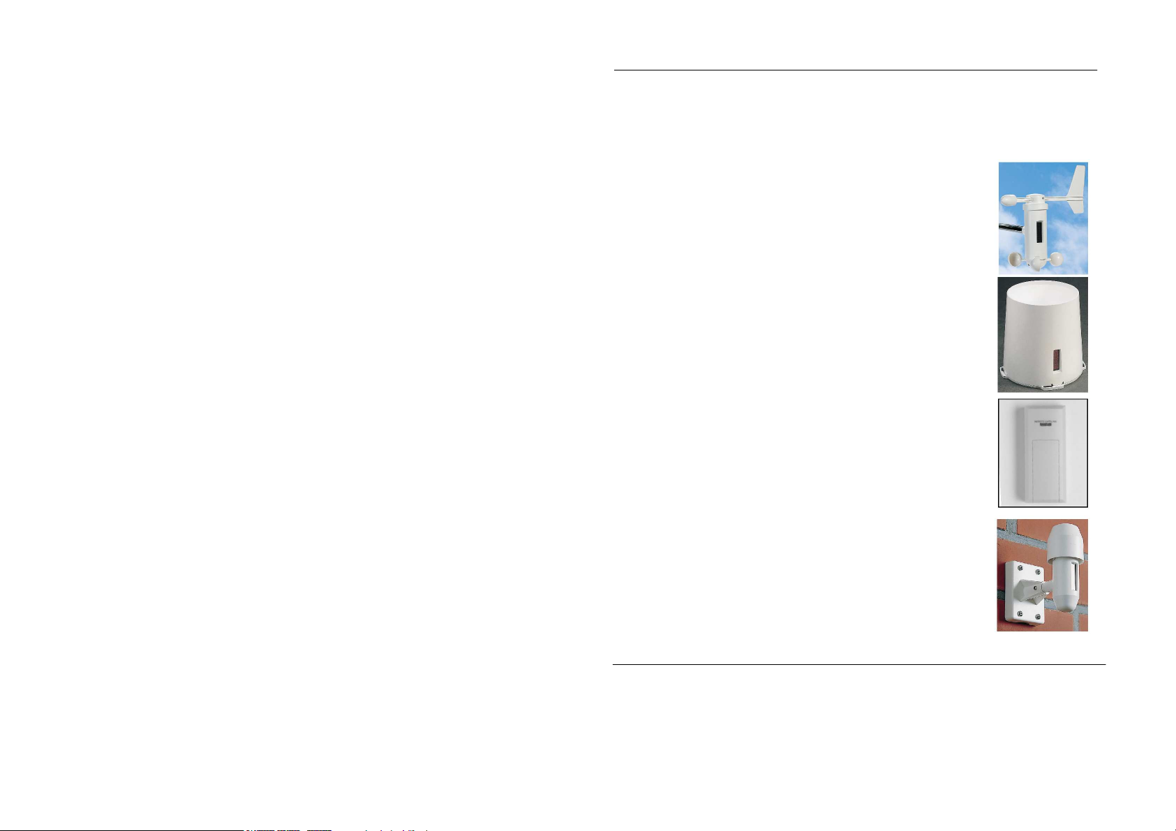
Remote Indoor Sensor
The Remote Indoor Sensor included with the basic shipment requires two Type Mignon
AA, IEC LR6, 1.5V batteries for operation. It contains one respective sensor for
temperature, humidity and air pressure. The data of the Remote Indoor Sensor generally
appear in the indoor display section in the upper left part of the LCD. Besides indoor
temperature and indoor humidity it measures the air pressure prerequisite for the display
of air pressure, air pressure tendency, weather tendency and air pressure history.
Remote Wind Sensor
The Remote Wind Sensor simultaneously acquires wind direction and wind strength at its
mounting location. It is operated by a solar cell with a battery backup during darkness and
provides addressing which cannot be altered by the user.
Remote Rain Volume Sensor
The Remote Rain Volume Sensor also works with solar power supply and provides
addressing not alterable by the user. The funnel has a 5.12 in (130 mm) diameter, which
represents an area of 20.45 in
2
, the calculation base for the rain volume.The amount of
water flowing through the funnel initiates a number of pulses. These pulses are converted
to in or mm in the Base Station and then displayed.
Remote Outdoor Sensor
The Remote Outdoor Sensor included with the basic shipment allows the transmission of
the temperature and humidity values at its mounting location.
This sensor can be addressed freely for display within the outdoor display section in the
upper right part of the LCD (see Display Overview). By default all Remote Outdoor
Sensors are set to Sensor 1. Individual addressing is however possible.
7. Mounting
Base Station
The Base Station can be placed on any smooth surface (e.g. table, bookshelf, etc.) by
pulling out the foldable stand or wall mounted at any desired location by means of a
hanging hole at the back of the device.
Important Note!
It is recommended to check that the 433MHz signals are properly received before
permanently mounting the Professional Weather Station (drilling of holes, etc.).
Should the Weather Station not pick up signal from the desired location a slight
relocation will help in most any case. Once the signals are received, the system can
be mounted permanently.
Mounting is but a preparation for the setup. Just before the final setup of the Base
Station the magnets have to be placed into the sensors.
Recommendation!
In order to test all sensor functions at first setup the sensors can prior to mounting
be placed on a smooth surface (table, etc.) and put into operation (see Item 8
Setting Up).
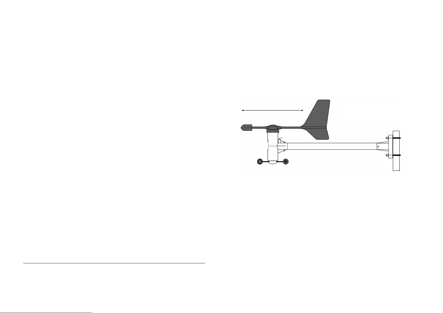
Remote Wind Sensor
South
North
Remote Wind Sensor to
a Mast
Magnet
Solar Cell
Mast
Mounting takes place either to a mast or at the upper rim of a wall. It is important to mount
the device in such a way that the solar cell in the sensor housing is pointing in a southerly
direction. It is further important to mount the device in a zone not prone to wind shadow,
i.e. the wind must be allowed to travel freely about the sensor from all directions.
Remove the transport protection from the sensor head and make sure that weather-vane
and wind wheel can move freely and easily. Put sensor head, holding tube and mast/wall
holder together and fix the components by use of the supplied screws. For basic
mounting the Wind Sensor must be pointing exactly in a southerly direction (solar cell to
the south) in order to provide an exact northerly reference point for the evaluation
electronics.
Note!
An exact southerly alignment of the sensor respectively its solar cell is very
important since this alignment will provide the reference point for the Wind
Direction Sensor.
In order to obtain correct measuring values exact perpendicular mounting of the
sensor to the mast must be observed. Axial stress to weather-vane and wind wheel
should be avoided.
Remote Indoor Sensor
Mount the sensor to its desired location. Keep in mind that the sensor is not designed to
operate outdoors or in rooms prone to excessive humidity. Data of the Indoor Sensor are
Page 5

generally displayed in the display section in the upper left part of the LCD. After insertion
Alignment of Rain Sensor, Use of
Polarity of the Color Marked
Magnet must correspond to
of the batteries the sensor is immediately operable.
Remote Outdoor Sensor
The mounting of the sensor should take place anywhere to the west or north since
temperatures in meteorology usually are measured in the shadow. It can however be
mounted at any other location if desired. It simply must be observed that the solar cell
powering the sensor does have to point towards the light in any case. The sensor must
not be obstructed by any close impediments such as leaves or the like since this will
prevent the solar cell from efficiently powering the sensor. A thinkable mounting location
would e.g. be a spot beneath the roof extension.
The sensor is designed for wall or mast mounting, which can be performed in the
following way:
Either mount the wall holder of the sensor in an exact perpendicular position to a wall by
means of four screws or to a mast by use of the supplied mounting bracket.
Place the sensor into the wall holder and secure both parts by use of the supplied screw.
Ensure that the large protective hood lies on top and the solar cell is pointing towards the
light.
During darkness and periods of bad weather with a relative lack of sunlight an internal
battery system buffered by the solar cell will take care of the sensor’s power supply.
Remote Rain Volume Sensor
Generally mount the Remote Rain Volume Sensor with its solar cell pointing in a southerly
direction.
The Rain Volume Sensor must be securely mounted to an exact horizontal surface by
means of its mounting holes in the bottom part of the housing. Prior to this remove the
upper part from the lower portion by pressing and turning the upper part clockwise with
regard to the bottom part. Remove the transport protection from the seesaw in the lower
part of the sensor and check by tilting that the seesaw can move freely and easily to its
both endpositions.
A cavity in form of a „T“ in the bottom part of the Rain Volume Sensor can be filled with
water and thus allows an exact horizontal alignment without any other auxiliary means.
Fill a small amount of water into this cavity and align the bottom part of the sensor by
principle of a spirit-level. After marking the exact mounting position the water can be
removed. Observe the southerly alignment for the solar cell. By doing this the short
leg of the engraved spirit-level must point to the north.
Magnet
Direction
South
Spirit-Level and Position of Pickup Magnet
Spirit-Level
Equal water level at all three ends
In order to reach the best possible remote
transmission (high transmission range) it is
recommended not to mount the Rain Volume
Sensor too close to the ground. Mounting the
unit at a height of appr. 3.3 ft (1 m) also reduces
the danger of pollution (especially the solar cell).
Observing the correct polarity insert the color
marked magnet into the holder.
Important Note!
In order to avoid start-up problems make
sure that the color marked magnet is inserted
observing the correct polarity as shown in
the Imprint
the illustration opposite.
After securely screwing the bottom part of the sensor to the mounting surface replace the
upper part as follows:
On the side of the counting seesaw for the rain volume in the bottom part of the sensor
there is a bar magnet mounted in the center initialising the counting pulses for the
electronics.
The top of the housing has now to be replaced in such a way that the solar cell is also
placed on the side of the magnet with the electronics part also directly opposite and the
three retaining hooks exactly fitting into the holders in the bottom part. Turn the upper part
carefully in a counter-clockwise direction until the retaining hooks tightly lock into place.
The Remote Rain Volume Sensor is now operable. For testing purposes very slowly pour
a small amount of water into the funnel. The collected amount will later be computed and
displayed in inch or mm in the Base Station.
Note!
When mounting the Remote Rain Volume Sensor make sure that the collected
water can drain off easily without any obstruction (even in case of sleet or snow).
8. Setting Up
Before setting up, the Intended Use as well as the various Safety
Notes and the Specifications have to be closely observed. Make
sure before setting up that the device does fit the intended
purpose for which you want to use it.
Activating the Sensors
The Outdoor Sensors for wind measurement, acquisition of rain volume and
measurement of outdoor temperature and humidity are for power supply equipped with a
solar cell as well as a Lithium buffer battery for periods of darkness and bad weather.
In oder to protect the precious batteries from over-discharging during long storage periods
without incidence of light to the solar cell (e.g. when packaged), the power supply is only
activated by means of a small magnet which must be inserted into the sensor from the
outside prior to first setup. The magnet belonging to the respective sensor should thus
only be inserted a short time before the Base Station is put into operation.
Page 6

Important Note!
In order to unambiguously assign the sensor data the Base Station should only be
put into operation after all sensors have been operating for at least 10 minutes.
This point is important since all sensors will at first work in a test mode for up to 10
minutes after the supply power has been applied (insertion of magnets into the Outdoor
Sensors and insertion of batteries into the Indoor Sensor). During this test phase the data
transmission takes place at a 4 second (approx.) pace rather than the 3 minute scan
applying lateron.
As with the Remote Outdoor Sensor the magnet for activation of the system must be
inserted into an opening provided for at the back of the unit. The magnet must tightly be
pressed into the opening and will stick out by appr. 4 mm.
The activation of the Remote Wind Sensor also takes place by inserting a small magnet
into the opening provided for. In this case the magnet holder is placed above the holder
tube mounting (opposite the solar cell).
In order to insert the magnet into the Remote Rain Volume Sensor the upper part has first
to be removed by pressing and turning the upper part in a clockwise direction with regard
to the lower part. In the center of the electronics casing there is a holder for the bar
magnet activating the electronics. Insert the color marked magnet according to its correct
polarity into the holder (also see Page 34).
After pressing the magnets into their holders the sensors will take up data transmission.
The Remote Indoor Sensor needs two Mignon AA, IEC LR6, 1.5V batteries for operation.
To insert the batteries the battery compartment needs to be opened. Insert the batteries
observing the correct polarity in accordance to the engraved polarity marking in the
battery compartment. Replace the cover of the battery compartment.
Approximately 12 minutes after activating the last sensor, insert four Mignon AA, IEC
LR6, 1.5V batteries into the Base Station observing the correct polarity.
Upon inserting the batteries into the Base Station a short initializing phase takes place
during which all segments of the LCD will shortly be displayed. Following this segment
test the Base Station will automatically switch into a so called test mode during which
each data reception is shown on the display and acknowledged by the sound of a signal
tone. For better distinction there generally is only the display of the sensor received last
while the data of all previously received sensors are being erased. The perfect reception
of all sensor data can thus be checked quickly and easily.
Note!
Under critical reception conditions this test mode also helps to find the best
possible location for good reception. To do this the respective sensor simply must
also be set to its test mode in order to transmit a data telegram every 4 seconds.
In order to activate this test mode the batteries from the Remote Indoor Sensor and
the magnets from the Outdoor Sensors have to be removed and re-inserted after a
waiting period of at least 60 seconds.
After approximately 30 minutes the Base Station will automatically terminate this test
mode and switch over to its normal reception mode. By pressing any function key the test
mode can be terminated earlier at any time.
Important Note!
For unambigious assignment of the sensor data, the test mode at the Base Station
should generally not be terminated as long as there is any sensor still in test mode.
After the test mode has finished (up to twenty minutes), it is necessary to set the time and
date. Press the two arrow keys (←←←←) and (→→→→) and the "Calibr.“ Key at the same time;
"0000 inHg“ will be displayed. Press the left arrow key twice to enter the time and date
mode. Press the "-“ key to advance the hour (please note the AM/PM setting), press the
"+“ key to advance the minutes, press the "Unit“ key to advance the month, and press the
"Sensor“ key to advance the day. It is important to set the time and date after set up of
the sensors to avoid problems.
For easy setup the Base Station can also be carried close to the mounting locations of the
sensors. This way the correct data transmission of the sensors can be checked.
The data of mounted sensors will after the test phase be transmitted at an approximate 3
minute pace and will be displayed in the various display sections of the LCD.
After all sensors have been received, their function can be tested as follows:
Indoor and Outdoor Temperature Sensors can be slightly warmed or cooled. A change of
temperature and humidity will be seen on the base station. This however may take up to 3
minutes.
The wind wheel of the Remote Wind Sensor should be turned at a moderate speed for
one to two minutes. The weather-vane of the sensor should be pivoted. The changes will
also become visible on the LCD.
To test the Remote Rain Volume Sensor at first the "Rain" key can be pressed several
times to get "Total“ rain display in case other rain records are being displayed. The
display "Total“ will appear. Now press the "Reset" key for about 3 seconds until a beep
tone sounds. Very slowly pour a small amount of water into the funnel, observing that
there is no slack water in the funnel at any time (this test should preferrably be performed
in kitchen or bath to avoid inconvenient splashes). Latest after 3 minutes the display of
the rain volume will be updated.
Page 7

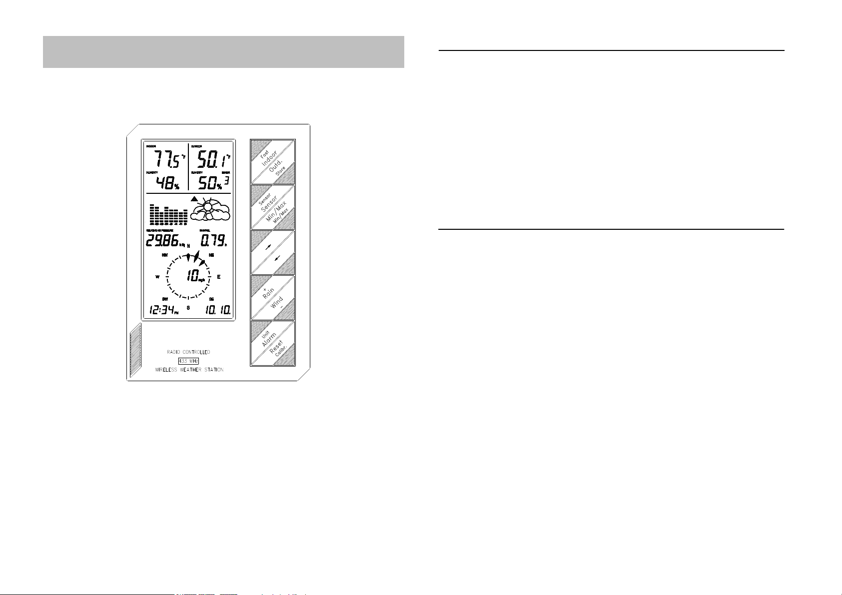
9. Display Overview
4
2
1
3
15
9
10
22
23
20
19
21
11
7
14
16
18
13
12
5
Note!
Unlike the real display the following illustration shows every display combination
possible in order to give a description of their appearance.
1. Temperature Indoor Sensor and
Indoor/Outdoor Sensor
respectively in degree Fahenreit
or Celsius
2. Current Indoor Measurement:
Temperature or Perceived
Temperature or Dew Point
3. Humidity Indoor Sensor and
Indoor/Outdoor Sensor
respectively
4. Temperature of selected
Temperature/Humidity Sensor
5. Current Outdoor Measurement:
Temperature or Perceived
Temperature or Dew Point
6. Identification Number of selected
Outdoor Sensor
7. Humidity of selected Outdoor
Sensor
8. Low Battery Indicator
9. Display of Air Pressure
10. Display of Air Pressure Unit:
inHg or hPa
11. Display of Rain Volume Unit:
in or mm
12. Display of Rain Volume
12. Display of Time Period of Rain
Volume: Total or last 24 Hours or
last Hour
14. Display of Air Pressure Tendency
15. Display of Air Pressure History of last 24 Hours
16. Icons for Weather Forecast
17. Display for Poll of Minimum Values
18. Display for Poll of Maximum Values
19. Display of Date of the Day
20. Display of Time
21. Display of Wind Strength Unity: mph, Knots or km/h or m/s or Beaufort
22. Display of Wind Strength or Wind Direction (in 5° Steps)
23. Compass, Display in 22.5° Steps with Display of Deviation Range at Changing Winds
10. Operation
After the installation of the Remote Sensors and the following setup of the Base Unit (test
mode of the Base Unit should generally be terminated after the test mode of the last
sensor) the transmitted and computed data will show on their respective display sections
on the LCD. If this is not the case please observe the notes on debugging on Pages 46-
47.
Note!
Please note that data can only be displayed if there is a respective sensor installed.
E.g. without a Rain Volume Sensor there will be no display of rain volume.
Since all relevant data is simultaneously displayed in the first place, operation will
essentially be limited to simple selection of further sensors or further weather data
by repeated pressing of the respective function keys.
Item "Operation“ solely pertains to operation in Normal Mode with the large key imprints
being applicable.
Programmable functions are thoroughly covered in Item "Programming Mode“ with the
small key imprints being applicable.
Indoor
In normal operating mode the indoor display in the upper left of the LCD displays the
temperature and humidity at the location of the Indoor Sensor.
By once pressing the "Indoor" key the Dew Point will be displayed. The Dew Point is
that point in temperature at which condensation of humidity begins and the so called
"Dewing“ takes place, i.e. the humidity is condensing and will precipitate in liquid form. So
the dew point for e.g. air with a water-vapour content of 17.4 g/m
3
lies at a temperature of
68ºF (20°C). If the dew point for water-vapor drops below 32ºF (0°C), the precipitation will
take place as snow or hard-frost.The dew point depends upon the concurrence of a
certain air pressure, temperature and humidity at the same time.
One more pressing of the "Indoor" key will lead back to the normal temperature display.
Wind
Pressing of the "Wind" key leads to the Change of Units for the Display of Wind
Strength respectively and the change from the display of the wind strength to a Digital
Display of Wind Direction in 5° steps within the compass (digital display field). The
order of changes and displays will be as follows:
- Wind Strength in mph
- Wind Strength in knots
- Wind Strength in m/s
- Wind Strength in km/h
- Wind Strength in Beaufort
- Display of Wind Direction in place of Wind Strength
Page 8

Display of Wind Direction in the
Display of Wind Strength in the
Digital Display Field
Digital Display Field
Rain
Pressing of the "Rain" key successively leads to the display of the Rain Volume of the
Last Hour (interval between the 30
th
minute and the 30th minute of the respective hour),
the Rain Volume of the Last 24 Hours (interval between 7.30h and 7.30h of the
respective day) and the Total Rain Volume (since start of measurements at Setup and
since last Reset) in the right center of the LCD.
Times and time intervals are in conformity with the International Rules for Professional
Weather Services.
Basic display: Total Rain Volume
Press once: Rain Volume of the last Hour
Press twice: Rain Volume of the last 24 Hours
Press three times: Return to Total Rain Volume
(see illustration at right)
If the "Reset" key is pressed for appr. 2 seconds during display of the Total Rain Volume,
the accumulated value of the Total Rain Volume will be erased and reset to zero.
Time and date of the reset will be stored in the weather station’s memory. Time and date
of the last reset can at any time be displayed by briefly pressing the "Reset" key.
If during switching of the Rain Volume Mode from Total to 1h or from 1h to 24h the
"Rain" key is held down for a longer period of time, the display will switch to an
accumulating counter. This mode of operation is indicated in the display by the symbol
"||" in front of the numerical value. Now e.g. during a rain shower the "running up“ of the
1h resp. 24h counter can be observed.
Minimum/Maximum Function
The Min/Max function allows the display of the minimum and maximum values of all
measurements since the last reset of the Min/Max memory. If desired, the time and date
of the appearance of the respective minimum and maximum values can also be
displayed.
Display of the Minimum/Maximum Values
Press once: Display of all Minimum Values
Press twice: Display of all Maximum Values
Press three times: Return to Display of the Current Values
During simultaneous display of all minimum or maximum values there will for the present
be no additional display of time and date. There will also be no weather symbols, no
display of air pressure tendency and no air pressure history. Instead there will be the
respective display MIN or MAX in the right center of the LCD.
If the clock not been manually set, then there will be no storage of any minimum or
maximum values.
Display of Single Values with their respective Time and Date
If during display of the minimum or maximum values one of the Arrow keys (←←←←) or (→→→→) is
pressed, nothing but the minumum or maximum value of the indoor temperature with its
respective assigned time and date will be diplayed.
Now by use of the Arrow keys and the Min/Max key each single minimum or maximum
value with its assigned time and date of storage can be selected.
Additionally with the maximum wind strength the wind direction at the time of storage will
be displayed.
Note!
During this display mode all other sections of the LCD will stay invisible.
Selective Reset of Stored Values
If during display of any selected minimum or maximum values the "Reset" key is pressed
for appr. 2 seconds, the respectively assigned minimum or maximum values will be
erased and reset.
Reset of all Stored Values
If during display of the minimum or maximum values the "Reset" key is pressed for appr.
2 seconds, all stored values will be erased and reset.
Alarm Function
As soon as any measurement of the Weather Station exceeds or falls below a set alarm
value, the air pressure tendency display, air pressure history, weather icon and wind
direction display will generally be switched off. The display then only shows the particular
section of the LCD where the value has fallen outside of the set alarm window. The
symbol "ALARM" will also be displayed.
If this does apply to more than one display or measurement section, their display will also
be shown in case of alarm.
By use of the "Sensor" key the alarm settings of the Outdoor Sensors can be scanned.
The alarm arriving first will including its assigned sensor identification be shown in the
display.
In case of alarm the Weather Station will stay in the "Alarm“ display mode until the
"Alarm" key is pressed and the display has thus returned to the display of their current
values.
In case of alarm there will additionally be an acoustic signal, which is composed of five
single tones. The signal will be repeated every 30 minutes for a total time span of max.
7.5 hours. The alarm will be terminated when the values of the respective measurement
section have returned to within their programmed value range as well as after additionally
pressing the "Alarm" key (Return to the display mode for the current data).
Page 9

Sensor Selection
The "Sensor" key allows in all operating modes of the Weather Station the selection of
the Outdoor Temperature/Humidity Sensors. The selected sensor will in the "Sensor“
display section be displayed with its assigned identification number.
Outdoor
In normal operating mode the outdoor display in the upper right of the LCD displays the
temperature and humidity at the location of the Outdoor Sensor selected by use of the
"Sensor" key.
By once pressing the "Outdoor" key the Dew Point will be displayed. By twice pressing
the "Outdoor" key the temperature display in this section will change to the display of the
Windchill Equivalent Temperature (Perceived Temperature). Windchill display will of
course only be possible if a Remote Wind Sensor is part of the Weather Station System.
One more pressing of the "Outdoor" key will lead back to the normal temperature
display.
The Windchill Equivalent Temperature (Perceived Temperature) is a fictive temperature
which is perceived by man under certain conditions instead of the really measured current
temperature and which can be taken to determine the comfort stage of a person wearing
suitable clothing at a certain temperature and wind strength. These conditions are
represented by a temperature of 91.4ºF (33°C) and a wind strength of 5.816 mph (2.6
m/s). Windchill is defined as the cooling effect on bare human skin at an assumed
constant skin surface temperature of 91.4ºF (33°C).
The "Perceived Temperature“ is approximately comparable to the so called "felt“ or
"sensed“ temperature, which is additionally considering the radiation effect of the sun,
light reflection of the clouds, wave length of light, etc.
This display does only make sense however if the Remote Outdoor Sensor responsible
for this display is placed at an adequate location. It is e.g. possible to place such a sensor
at a roofed terrace which is exposed to outdoor temperature and wind.
Windchill display will of course only be possible if a Remote Wind Sensor is part of the
Weather Station System.
11. Programming Mode
In programming mode all the minimum and maximum value settings for the alarm
functions can be performed.
Please observe that for this mode only the imprints below the functions keys will apply. If
the "Store" key is pressed or no key is pressed for about 60 seconds the device will
automatically switch back to its normal operating mode.
In order to enter the Programming Mode both Arrow keys (←←←←) and (→→→→) must be pressed
simultaneously. The display will now show the set minimum alarm value. Weather icons,
air pressure tendency display, air pressure history and compass will be switched off.
By once pressing the "Min/Max" key, the maximum alarm value will be displayed. By
again pressing the "Min/Max" key, the system will return to the display of the minimum
alarm value. The alarm values, such as for exceeding or falling below a certain ground
temperature, for a certain wind strength, etc., can now be set in Programming Mode. By
pressing the "Store" key the Programming Mode can be left.
Setting of the Minimum/Maximum Alarm Values
By use of the Arrow keys (←←←←) and (→→→→) and possibly the "Sensor" key select the desired
measuring point or measuring value respectively. All other displays will stay switched off.
Minimum/Maximum Selection
In this mode the mimimum or maximum values can be arbitrarily set by use of the
"Min/Max" key. The key functions as well as the functional sequences are identical to the
ones in Item Minimum/Maximum Function above. If desired, it is this way possible to
either firstly set all minimum values, followed by all maximum values or immediately set all
assigned minimum and maximum values to each respective measuring point. Only one
maximum value can be set for the wind strength. In order to enter this value a switch from
Min to Max must be performed.
Setting of Values
By use of the "+“ and "–“ keys the desired numerical values can now be set. By holding
the keys down, the device will automatically count up or down.
There is the additional possibility to speed up the counting by a factor of 10 by
simultaneously pressing the "Fast" key and either the "+" or the "–" key.
12. Calibration
All one time settings will be performed in Calibration Mode. This applies to the Altitude
Correction for the Barometric Air Pressure and the Calibration of the Rain Volume Sensor
as well as the setting of the desired Units for Air Pressure and Rain Volume. The time and
date can also be set in Calibration Mode. Further, if desired, the addresses of the Indoor
Sensor to be received, of the Wind Sensor and of the Rain Volume Sensor can be
changed in this mode.
The Calibration Mode can be entered by simultaneously pressing the (←←←←), "Calibr." and
(→→→→) keys. The respective display section can then be reached by use of the (←←←←) and (→→→→)
keys.
Setting of the Altitude Correction for the Barometric Air Pressure
After selecting the air pressure display section the altitude of your location with regard to
sea-level (H.a.SL – Height above Sea-Level) can directly be entered in Meters (values
from 0 to 1999 m possible) by use of the "+" and "–" keys and possibly the "Fast" key.
The setting of display units in hPa or inHg is of no significance for the Altitude Correction
for the Barometric Air Pressure.
By pressing the "Store" key the set value is stored and the display will return to the
normal operating mode.
Calibration of the Rain Volume Sensor
Note!
The Rain Volume Sensor by design and manufacturing already offers a very high
accuracy and will for normal operation not require any special calibration.
Calibration may only be necessary for extremely high accuracy demands.
Before starting the calibration of the Rain Volume Sensor any possibly already
accumulated rain volume value has to be erased and reset to 0 in normal display mode
according to Item Rain of this manual (leaving the Programming Mode).
Following this procedure pour exactly one Liter of water during an arbitrary time span very
slowly into the funnel of the Rain Volume Sensor.
Page 10

Caution!
Fast pouring will corrupt the measuring results! Pour the water so slow into the
funnel, that there is no slack water in the funnel at any time.
Recommendation!
In order for the water not to run too fast into the funnel, thus causing a faulty
calibration, place a small cup made of synthetic material into the funnel. Prepare
the cup by piercing a small hole into the bottom using a sharply pointed tool. The
water will now enter the funnel very slowly drop by drop.
Because of the 5.118in (130mm) diameter of the funnel, representing an area of 20.574
2
in
(0.0133m2 ), the amount of 1 Liter of water will yield a nominal rain volume of 2.97 in.
After the entire amount of water has run through the funnel the actual value (displayed
value) will show on the display, in the ideal case 2.96 in.
The ratio of Target Value to Actual Value will yield the Calibration Factor. Since this
calibration factor may have already been entered at an earlier date, it has to be included
in the calculation.
The new Calibration Factor can be computed in the following equation:
New Calibration Factor =
Target Value (e.g. 2.96 in) x Old Calibration Factor
Actual Value (Display after passing 1 Liter of Water)
The old calibration factor can be viewed by simultaneously pressing the
(←←←←) and (→→→→) keys as well as the "Calibr." Key in Calibration Mode. Select the display
field for the Rain Volume Sensor by use of the (←←←←) key.
Correct the calibration factor to its new value by use of the "+" and "–" keys and possibly
the "Fast" key.
By pressing the "Store" key the set value is stored and the display will return to the
normal operating mode.
Change of Units
If the "Units" key is pressed in Calibration Mode, the display section "Rain" will allow the
selection of the units inch or mm and the display section "Air Pressure" will allow the
selection of the units inHg or hPa, and the display section "Indoor temperature“ will
allow the selection of the units ºF or ºC.
Manual Time Setting
To do so press the Arrow (←←←←) key twice in Calibration Mode. The display will show time
and date only. Setting is then performed according to Table 1. After entering the time and
date the "Store" key must be pressed.
Table 1: Setting of Time and Date
Function Key
Hours
Minutes
-
+
Month Units
Date of Day Sensor
Storing Store
Addressing of Remote Sensors WS 7015-22, WS 7015-28 (optionally) and Remote
Outdoor Sensor
The outdoor sensor concept allows the simultaneous operation of up to 8 outdoor
sensors. Their data are displayed in the upper right display section for the outdoor values.
Each sensor in the system is assigned a sensor address, allowing the receiver to
integrate the sensor into the overall system free from interference. By default the Remote
Outdoor Sensor included in the
shipment is set to be Sensor 1, while
the types WS 7015-22 and WS 701528 are both set to be Sensor 2. The
programmable assignment can be
seen from opposite illustration.
The addressing can be performed by
the user by means of coding bridges
(jumpers) on the wiring side of the
sensor‘s PCB. To do this the protection
hood has firstly to be removed by
unscrewing from the Remote Outdoor
Sensor and then the housing must be
opened by removing the screws on its
back. Both types WS 7015-22 and –28
only need to have their back covers
unscrewed.
Following this the coding bridges can be set according to the addressing table opposite.
Change of Base Address for Sensors with fixed Assignment
Setting of addresses for the Remote Indoor Sensor, Remote Rain Volume Sensor and
Remote Wind Sensor is not required under normal operating conditions.
Multi functional operation is a special feature, allowing to generally operate an arbitrary
number of Base Units within the transmission range of the Remote Sensors. One Base
Station can be placed in the living room, one in the office, etc., all displaying the same
data.
If in every room, in which a Base Station
(Display Unit) has been placed, the indoor
temperature of this particular room needs to
be displayed on the upper left section of the
LCD, then the indoor sensors for
temperature/humidity and air pressure need
to be assigned different base address
according to the illustration opposite.
In order for the Base Station to exclusively
receive its assigned sensor here also a
respective address has to be set. To change
the base address in Calibration Mode the
(←←←←)key must be pressed three times and the
desired base address selected by use of the
"Indoor" key.
The base addresses of the Wind Sensor and the Rain Volume Sensor can also be
changed in this operating mode which however is only necessary in very rare cases. A
Page 11

change of address is only required if two neighbouring Wind Sensors or Rain Volume
Sensors are placed within the reception range of the Base Station. The base address of
the Wind Sensor and the Rain Volume Sensor can only exclusively be changed by the
manufacturer, thus requiring the units to be shipped back to the manufacturer, if
necessary.
Note on Storage of Solar Powered Outdoor Sensors
These sensors receive their operating power from a solar cell which also powers an
internal battery to be used during periods of darkness and bad weather.
If any such sensor is taken out of operation for a longer time period without any light there
still is no danger for the internal battery as long as the small magnet required for
activation of operating power has been removed.
This way a sensor in its packaging can be stored for several years.
13. Battery Change
Remote Indoor Sensor, Remote Sensors WS 7015-22, WS 7015-27 and WS 7015-28
The batteries in these sensors have a life expectancy of up to 3 years (Alkaline Batteries).
They have to be changed, if the display of the respective sensor in the base station fails
to appear for a time period exceeding 24 hours and any general and longer lasting
interference of the transmission path is out of the question. The latter can generally be
recognized if the data transmission of other sensors being close to the one missing also
do not work properly (see Item Interferences).
Batteries can be changed by opening the battery compartment of the sensor, removing of
the used-up batteries and replacing them with new Type Mignon AA, IEC LR6, 1.5V
batteries under observance of the correct polarity as marked in the battery compartment.
After replacing of the battery cover the sensor is ready to operate again. Latest after the
Base Unit has performed its standard search routine (see Item Interferences), the data of
the sensor must again appear on the display.
Base Station
The Base Unit indicates low running batteries by a battery icon in the top portion of the
LCD.
Since stored data may be lost during battery change it is recommended to call off and
note all data, if required, prior to battery change. Then open the two battery covers on the
back of the casing, remove the used-up batteries and replace them with four new Type
Mignon AA, IEC LR6, 1.5V batteries under observance of the correct polarity as marked
in the battery compartment.
The end user is obliged by law (Battery Regulations) to properly dispose
of all used-up batteries and accumulators (button cell to lead-acid
accumulator). Disposal of such items through the garbage is strictly
forbidden.
Used-up batteries can be returned to all municipal recycling centers which
are obliged to accept such items.
Please participate in the preservation of the environment!
Note!
Other parts of the system do not require any battery changes since they are
powered by solar cells. Integrated buffer batteries will cover periods of darkness
and bad weather.
14. Interferences
If any sensor has not been received for a period of 12 hours, its display will cease to show
its values on the LCD. If by temporary disturbances of the transmission path the
synchronization between sensor and base unit is interrupted (transmission only takes
place in a very small time window), the base station will scan all sensor transmitters for 6
minutes at 8.00h a.m. and 6.00h p.m. every day. Latest after that time a temporarily
interrupted reception should be resumed.
Possible interferences preventing correct display of transmitted measurement
values:
Undefined values after setting up.
In order to immediately receive defined data and ensure the correct assignment of all data
telegrams to their display section make sure, that the test mode of the Base Station is
only be terminated after all sensors have ended their test phase.
No reception – distance between transmitter and receiver too long.
Reduce distance between transmitter and receiver. Use Repeater (WS-7015-12) to
extend transmission distance.
No reception – highly shielding materials between transmitter and receiver (thick
walls, steel concrete, isolating aluminum foil, etc.).
Find different location for transmitter and/or receiver. See also Item Transmission
Range.
Low batteries in transmitter or receiver.
Change batteries. Observe low battery indicator.
Transmitter is superposed by interfering sources (e.g. wireless radio, headset,
speaker, etc.).
Remove interfering source. Find different location for transmitter and/or receiver. Has no
reception taken place for the last 12 hours, the respective measuring point is shut down
and no measuring value will show, since the system is assuming a sensor no longer in
existence. In order to save battery power there will be no more reception attempts. Every
day at 8.00h a.m. and 6.00h p.m. the receiver will automatically start a new
synchronization whereby a sensor not received for more than 12 hours will be
incorporated into the system again.
Note!
Every newly added Remote Sensor (e.g. after a battery change) will automatically
be entered into the system and its respective data will be displayed.
Quite frequently interferences are only of a temporary nature (e.g. R/T operation) or can
easily be overcome. If there are wireless headsets, remote babysitters or other devices
working on a 433MHz basis in your house or vicinity, their switch-on time is mostly limited.
Page 12

Furthermore most of these devices allow the change to an interference-free frequency.
Such measures will effectivelly overcome interferences.
Remote Sensor does interfere with other devices in the 433MHz range.
The transmissions of the Remote Outdoor Sensor can temporarily (for about 200 ms
every 3 minutes) interfere with other devices working on the same channel. These
interferences are of very short duration and can thus be neglected. If possible, the
channel should be changed at the respective device.
15. Transmission Range
The transmission distance in open field with free range of sight between transmitter and
receiver reaches under optimum conditions 330 ft (100 m). Walls and even steel concret
constructions will be penetrated at a considerable loss of transmission distance. A loss of
distance can have the following reasons:
- High frequency interferences of any kind.
- Constructions of any kind or vegetation.
- Especially for the Wind Sensor the transmission distance can be influenced by metal
roofs or aluminum foil roof isolation.
- The distance of transmitter and receiver to conducting planes or object (including the
human body or the ground) does influence the transmission characteristics and thus
the transmission distance.
- Broad band interferences in municipal areas can reach levels reducing the
signal/noise ratio over the entire frequency band, thus also reducing the
transmission distance.
- Devices working at closely neighbouring frequencies may also influence reception.
- Poorly shielded PCs can irradiate the receiver and thus reduce transmission
distance.
- For extension of transmission distance the optionally available Repeater (WS-7015-
12) can be used.
16. Cleaning and Maintenance
- Clean the housing and screen of the Base Station only with a soft, damp cloth. Do
not use abrasives or solvents.
- Ensure that the Remote Rain Volume Sensor does not collect leaves or other dirt.
Remove the funnel from the Rain Sensor every now and then and clean it under
running water. Also clean the seesaw of the sensor with a damp cloth and check by
lightly tapping with your finger that it can move freely from side to side.
Do not clean the funnel with attached bottom part of the Rain Sensor nor the bottom
part itself under running water. This may bear the danger of water entering the unit’s
electronic parts.
- Do not immerse the Base Station in water.
- Please do not attempt any repairs on your own. It is recommended to have repairs
only performed by trained personnel at the point of purchase. Opening or improper
handling of the units will void the warranty.
17. Disposal
If the Professional Remote Weather Station happens to become inoperable and must be
disposed of please do this in accordance with the valid legal regulations.
18. Specifications
Measuring Interval Outdoor Sensor:………………… Appr. 3 minutes
Measuring Interval Indoor Sensor:………………….. Appr. 3 minutes
Transmission Frequency:…………………………….. 433.92MHz
Transmission Distance in Open Field:………………. 330 ft max. (100 m max.)
Temperature Range Indoor:………………………….. 32ºF to 158ºF (0°C to +70°C)
Temperature Range Outdoor:……………………….. -22ºF to 158ºF (-30.0°C to +70°C)
Resolution:………………………………………………0.1ºF (0.1°C)
Accuracy:……………………………………………….. ±2º (±1°C)
Measuring Range Rel. Humidity:…………………….. 20% to 95%
Resolution:………………………………………………1%
Accuracy:……………………………………………….. 8%
Measuring Range Air Pressure:…………………….. 23.62 to 32.48 inHg
(800 to 1100 hPa)
Resolution:………………………………………………0.03 inHg (1 hPa)
Accuracy:……………………………………………….. ±0.03 inHg (±1 hPa)
Air Pressure Variation:…………………………………Bar Diagram, Scaling 2 hPa/
1,5 mmHg per Divider
Rain Volume Display:…………………………………..0 to 157.4 in (0 to 3999 mm)
Resolution:………………………………………………<0.02 in (< 0.5 mm)
Accuracy:………………………………………………. 0.04 in (2%±1 mm)
Wind Strength:…………………………………………. 0 to 124 mph (0 to 200 km/h)
Resolution:………………………………………………0.1 mph (0.1 km/h)
Accuracy:……………………………………………….. 0.6 mph (3%±1 km/h)
Wind Direction:………………………………………… Grafical Resolution 22.5 Degrees,
Numerical Resolution 5 Degrees
Power Supply Base Station:…………………………. 4 x Type Mignon AA, IEC LR6, 1.5V
(Alkaline)
Measurements Base Station (L x W x H):…………. 8.54 x 1.18 x 6.29“
(217 x 30 x 160mm)
 Loading...