

La Crosse Technology WS-1910 User Manual
WEATHER CENTER
Instruction Manual
Table of Contents
Topic Page
Inventory of contents
Features 3
Setting up 6
Function keys 12
LCD screen 14
Manual settings 16
Weather forecast and weather tendency 32
Wind speed measurement 36
Rainfall measurement 37
Viewing history data 37
Viewing the MIN/MAX weather data 39
Outdoor transmission 915 MHz reception 48
Positioning 49
Care and maintenance 53
Specification 54
Warranty Info 57
1
WEATHER CENTE R
INTRODUCTION:
Congratulations on purcha s in g this st at e- of- t he- art w eat h er stat ion as an ex a mp l e of
excellent design and innovative measuring technique. Featuring time, date, calendar,
weather forecast, wi nd gust and wind speed, indoor/outdoor temperature and outdoor
humidity, air pressure and rainfall (optional), this weather station will provide you with
various weather informat ion an d weat h er for e cast. Page s aft er p ages, y ou will di sco v er
that the operation of your weather station is really simple !
This product offers:
INVENTORY OF CONTENTS
1. Wireless Weather Station
2. Wireless Thermo-hygro Sensor (TX31U-IT) and Wind Sensor (TX55U-IT) with
mounting bracket.
3. Instruction Manual
Instruction Manual
INSTANT TRANSMISSION is the state-of-the-art
new wireless transmission technology,
exclusively designed and developed by LA
CROSSE TECHNOLOGY. INSTANT
TRANSMISSION offers you an immediate update
(every 4.5 seconds!) (6.25 seconds for rain
sensor - optional) of all your outdoor data
measured from the transmitters: follow your
climatic variations in real-time!
FEATURES:
The Weather Station
LCD
Time display (manual setting)
12/24 hour time display
Calendar display (weekday , dat e, mo nt h, year)
Weather forecast icons and weather tendency indicator
Indoor temperature display in °C/ºF
Outdoor temperature display in °C/ºF
Outdoor Humidity display as RH%
Dew point displayed in ˚C or ˚F
Wind chill displayed in ˚C of ˚F
Wind gust displayed in km/h, mph or m/s
Wind speed displayed in km/h, mph or m/s
24-hour and total rainfall dis p layed in mm or inch (optional)
Display MIN/MAX value of outdoor temperature, outdoor humidity, dew point, wind
chill, and relative air pressure, with time & date of recording
Display MAX wind speed, MAX gust and MAX 24h rainfall (optional) with time &
date of recording
Relative air pressure display ed in hPa or i nH g
Air pressure tendency indicator for the past 12 hour (bargraph format)
Function keys
2
Hanging hole
Battery
compartment
cover
Foldout stand
3
4
Manual reset of outdoo r temperature/ humidity, pressure and windchill data
s
t
-
r
r
LCD contrast selectable
Low battery indicator
Storage of 140 sets of history w eather dat a r eco r ded in 3- h ou r int er v al s
Wireless transmission at 915 MHz
Transmission range up to 330 feet/100 meters
The Thermo-hygro Tr an smi t t er
The Wind sensor
The rain sensor (optional- sold separately)
SETTING UP:
Remote transmission of the out d oo r t emp er at ur e a nd h um i dity to the
Weather Center at 915 MHz
Rain proof casing
Wall mounting case (to be mounted in a sheltered place. Avoid direct
rain and sunshine)
Connected to the thermo-hygro transmitter by
cable
Can be installed onto a mast or a horizo nt al
panel
Remote transmission of the rainfall data to the
Weather Center at 915 MHz
To be mounted onto a horizonta l pan e l
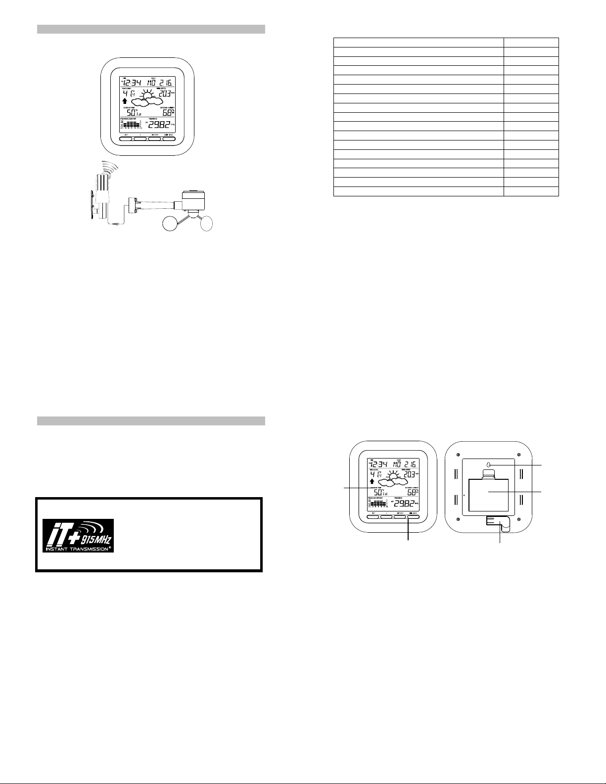
Weather center
Note:
When putting the Weather St atio n into operation, it is
important to perform in close prox im it y (e.g. on a tab le) a
complete wiring and set-up of the system. This step is
important to test all components for correct function before
placing and mounting them at their final destinations (See
Positioning below):
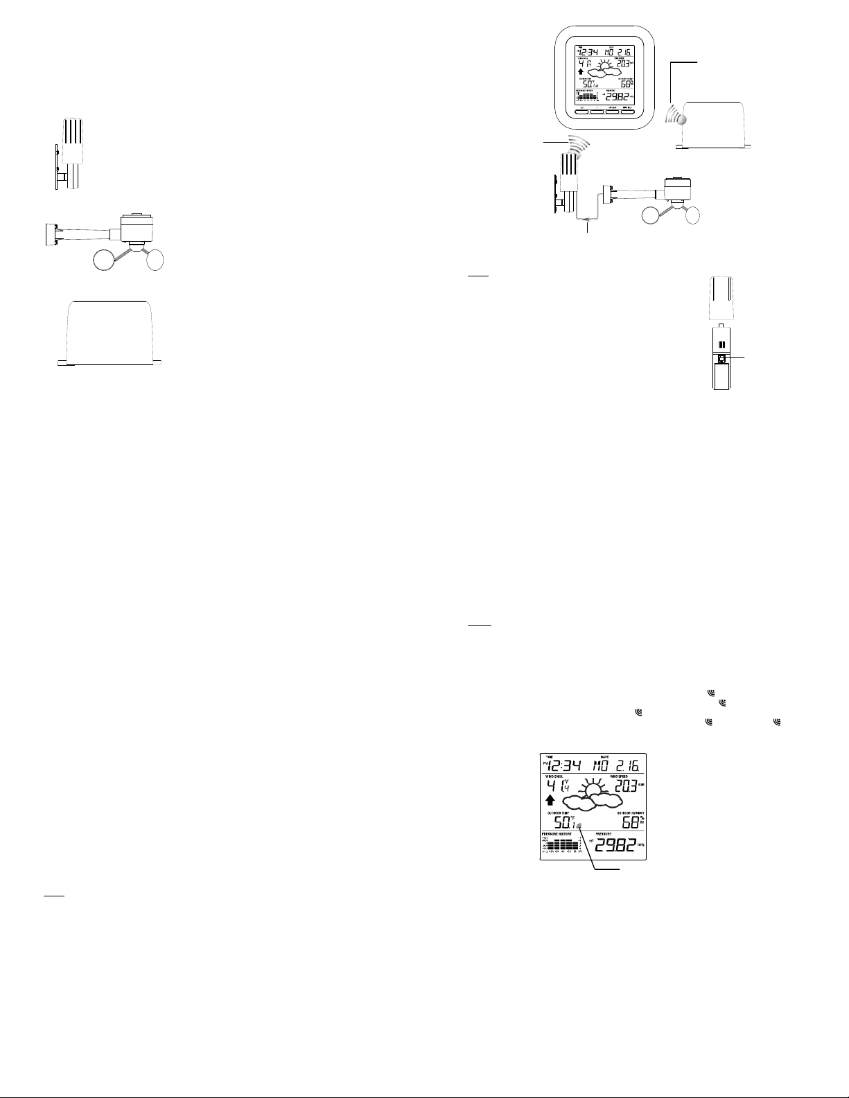
1. Unwind the cables of the Wind sensor. Connect the
Wireles
transmission a
915 MHz - thermo
hygro transmitte
to weather station
Thermo-hygro
transmitte
Cable connection between the wind sensor and
the thermo-hygro transmitter
Wind sensor to the Thermo-hygro transmitter by
plugging the connector head into the socket of the
Thermo-hygro sensor.
Rain sensor (optional)
OPTIONAL
Wireless transmission
at 915 MHz – Rain
sensor to weather
station
Wind sensor
Socket for wind
sensor
2. First insert the batteries into the The r m o-hygro sensor and Rain sensor (purch as e
separately) “How t o install and replace the batteries into the Thermo-hygro
sensor“ and “How to install and repla ce the batteries into the Rain sensor
(optional)” below).
3. Then insert the batteries into the Weather C enter (see “How to install and replace
the batteries into the Weather Center” below). Once the batteries are installed, all
segments of the LCD will light up bri ef ly . It will the n di spla y the time as 12:00, the
date as 1.1.09, the weather icons, and air pr e ss ur e value. " - - -" will be shown for
outdoor data.
4. Afterwards, the Weather Center will start rec eiving data from the transmitter. The
transmission recepti on i co n will be b lin k in g to ind ic at e that t he stat i on i s trying to get
the thermo-hygro tr ansmitter data. The outdoor temperature, humidity, wind data
should then be displayed on the Weather Center. If this does not ha pp en aft e r 13 5
seconds, the batterie s will need to be removed fr om all units. You will have to start
again from step 2.
5. The transmitter reception ic on is n ow blink in g ag ain t o in d ic at e th at th e stat i on i s
trying to get the rain sensor data. It will stop blinking once the rain sensor has been
detected. If this does not happen after 135 seconds, you will need to start again from
step 2.
6. You may need to check th e cable for correct connection and all the components for
correct function by man ually turning the wind-gauge by moving the wind-vane; tilting
the rain sensor to hear the impact of the internal moving seesaw, etc. (see
Positioning below).
7. Time and date shall be manually set (See Manual Setting below).
8. After the Weather Center has been check ed for co rr e ct fun ctio n w ith re g ard to the
above points and fou nd fit, the initial set up of the weather station system is finished
and the mounting of the system components can take place. It must be ensured
however that all components work properly together at their chosen mounting or
standing locations. If e.g. t her e a ppear to be problems with the 915 MHz radio
transmission, they can mostly be overcome by slightly changing the mounting
locations or turning the base station.
Note:
The radio communication between the receiver and the transmitters in the open field
reaches distances of max 330 feet/ 100 met er s, pr ov ided t h er e are n o inte rfe rin g ob st acl es
such as buildings, trees, vehicles, high voltage lines, etc.
5
9. Radio interferences created by PC screens, radios or TV sets can in some cases
entirely cut off radio communication. Please consider this when choosing standing or
mounting locations.
Note :
After batteries are installed in the transmitter, install the batteries in the weather
center to receive the signal from the t r an s mitt er s as s oo n as poss ible. I f t he w eat her
center is powered more than 5 hours after the transmitter is powered, the weather
center will never receive signal successfully from the transmitters. In this case, user
will need to reinstall the batteries from all the transmitters to redo set-up procedure.
After batteries are installed, there will be synchronization between Weather Center
and the transmitters. At this time, the signal reception icon
the signal is successfully received by the Weather Center, the
switched on. (If it is not successful, the
can easily see whether the last reception was successful (
off). On the other hand, the short blinking of the icon shows that a reception is in
progress.
If the signal reception is not successful on the first frequency (915MHz) for 45
seconds, the frequency is changed to 920MHz and the learning is tried another 45
seconds. If still not suc c essful, the reception is tried for 45 seconds on 910MHz. This
will also be done for re-synchronization.
6
will be blinking. When
icon will not be shown in LCD) So the user
Transmitter signal
reception icon
icon will be
icon on) or not ( icon
7
8
y
y
A
y
r
y
r
y
HOW TO INSTALL AND REPLACE THE BATTERIES INTO THE THERMOHYGRO TRANSMITTER
Note:
In the event of changing batteri es in any of the units, all units need to be reset by following
the setting up procedures. This is because a random security code is assigned by the
thermo-hygro sensor at start-up and this code must be received and stored by the
Weather Center in the fi rst several minutes of power being supplied to it.
HOW TO INSTALL AND REPLACE THE BATTERIES INTO THE WEATHER
STATION
The outdoor Thermo-hygro tran smit t er works with 2 x AA IEC LR6,
1.5V batteries. To install and re p la ce th e bat t er i es, pl ea s e follow
the steps below:
1. Uninstall the rain cover of the transmitter.
2. Remove the battery compartment cove r.
3. Insert the batteries, observing the correct polarity (see the
marking in the battery compartm ent ).
4. Replace the battery cover and the rain cover onto the unit.
The Weather Station works with 3 x AA, IEC LR6,
1.5V batteries. When the batteries need to be
replaced, the low battery symbol will appear on
the LCD.
To install and replace the batter i es, ple a se f ol low
the steps below:
1. Remove the battery compartment cover.
2. Insert the batteries observing the correct
polarity (see the marking in the battery
compartment).
3. Replace the battery cover.
HOW TO INSTALL AND REPLACE BATTERIES INTO THE RAIN SENSOR
(OPTIONAL; SOLD SEPERATELY)
1. Unlock the main cover from the rain sensor base and remove the cover.
2. Remove the battery cover at the top of the ra in se ns or.
3. Insert 2 x AAA, IEC LR3, 1.5V batteries into the battery compartment, observin g t he
correct polarity.
4. Replace the battery cover and the main co ver o n th e unit.
Note:
In the event of changing batteri es in any of the units, all units need to be reset by following
the setting up procedures. This is because a random security code is assigned by the
transmitter and rain sensor (optional) at start-up and this code must be received and
stored by the Weather Station in the first 90 seconds of power being supplied to it.
BATTERY CHANGE:
It is recommended to replace the batteries in all units regularly to ensur e opt i m um
accuracy of these units. (Battery life –see Specifications)
Note:
The stored History record will not be kept af t er th e battery change is done on the weather
station.
FUNCTION KEYS:
Weather Station:
The Weather Station has 4 easy-to-use function keys.
Figure 1
Please participate in the preservation of the environment. Return used
batteries to an authorised depot.
Figure 2
Figure 3
SET key
Press and hold to enter manual setting modes: LCD contrast, Manual time setting,
Press to toggle between the display of Mode 1 or Mode 2:
Press to activate the reset mode when MAX or MIN record is shown
+ key
In display Mode 1, press to toggle between the display of date, weekday + date,
In display Mode 2, press to toggle between t he display of Relative Pressure, 24 hour
Press to adjust (increase) the level of different settings
Press to confirm to reset the MIN/MAX record
HISTORY key
Press to display the weather data history records
Press to exit manual setting mode
SET ke
+ ke
12/24 hour time display, Calendar setting, ºC/ ºF temperature unit, Wind speed unit,
Rainfall unit, Pressure unit, Relative pressure reference setting, Weather tendency
threshold, Storm threshold setting
Mode1: "Wind speed + outdoor t em p + r el. pr e ss ure"
Mode 2: "Gust + Dew P oint temp + rainfall data (only if there is a rain sensoroptional)"
(Mode 2 displayed will be shown for 30 seconds. Then it will return to normal display)
Indoor temp, or second
rainfall and Total rainfall (only if there is a rain sensor- optional).
9
MIN/MAX key
HISTORY key
MIN/MAX key
Press to display MIN/MAX records of various weather data
Press to adjust (decrease) the level of different settings
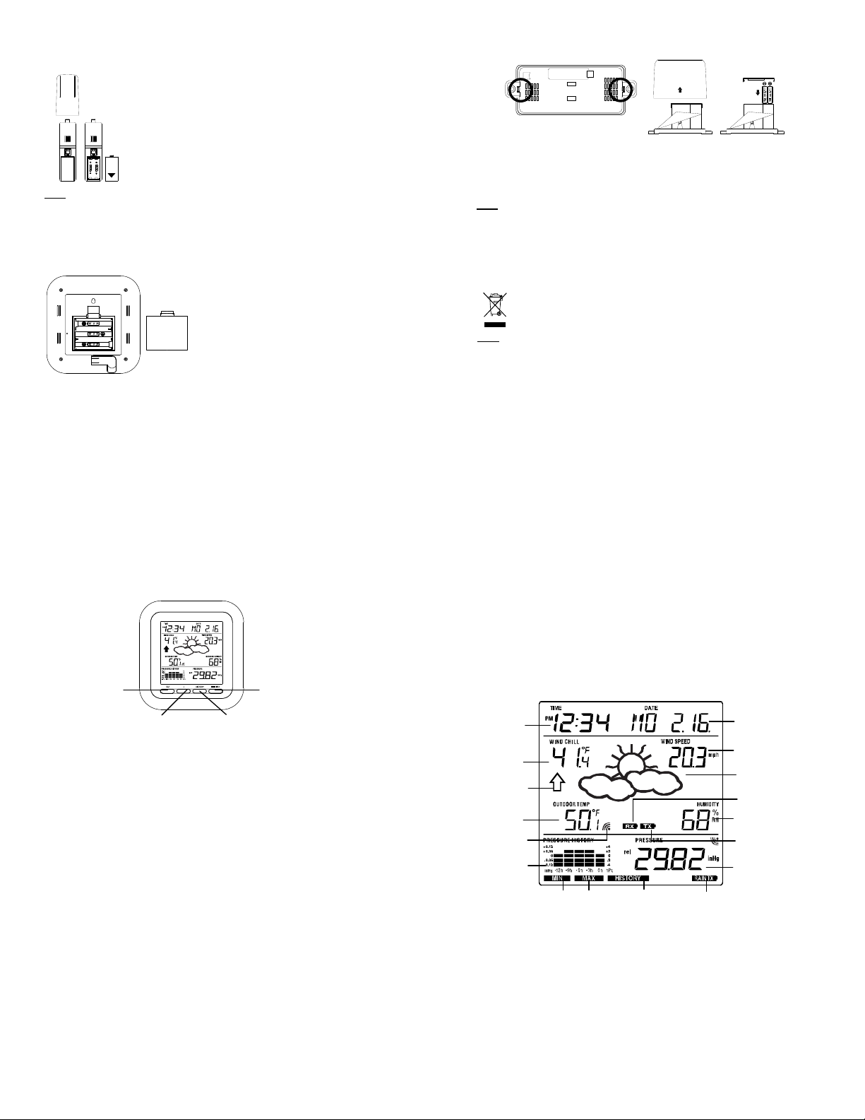
LCD SCREEN
The LCD screen is split into 3 sections di sp laying the following informatio n:
1. Time and date/ indoor temp/ second
2. Wind data, outd oor te m p erat ure and humidity, dew point, we ath er f or ec ast icon and
tendency indicator
3. Air pressure history, relative air pressure, rainfall data (optional)
Time displa
Wind Chill in
˚C or ˚F
Weather tendenc
indicato
Outdoo
temperature
/ dew point
in C or F
ir pressure
MI/MAX icons
Transmitter signal
reception icon
history histogram
# When the signal from the transmitter/ or Rain sensor (optional) is successfully received
by the Weather Station, this icon will be switched on. (If not successful, the icon will not be
shown on the LCD). User can therefore easily see whether the last reception was
successful (“ON” icon) or not (“OFF ” ico n). On th e ot her h and, the s hort blinking of the icon
shows that a reception is being don e at that ti m e.
10
HISTORY
icon
Low batter
indicator (rain
sensor - optional)
Calendar / indoor
temperature / seconds
display
Wind speed / gust* in
mph, km/h, m/s
Weather forecast
Icon
Low battery indicator
(weather station)
Outdoor relative
humidity in %
Low battery
indicator #
(transmitter)
Relative air pressure /
24 hr rainfall / Total
rainfall display* (only if
there is a rain sensor
being used)
11
12
 Loading...