

La Crosse Technology WS-1517 Instruction Manual
Professional Wireless Weather Station
Model WS-1517 | Instruction Manual
La Crosse T echnology
Weather Station that pr ov ides accur ate, real-time weather data straight from your backyard. This sleek weather stat ion
offers weather forecasting, indoor/outdoor t em per ature & humidity, wind & rain data, and precise atomi c time & date—all
on one comprehensive device.
®
, the world leader i n atomic time and weather instrument s, introduces a Professional Wireless
1
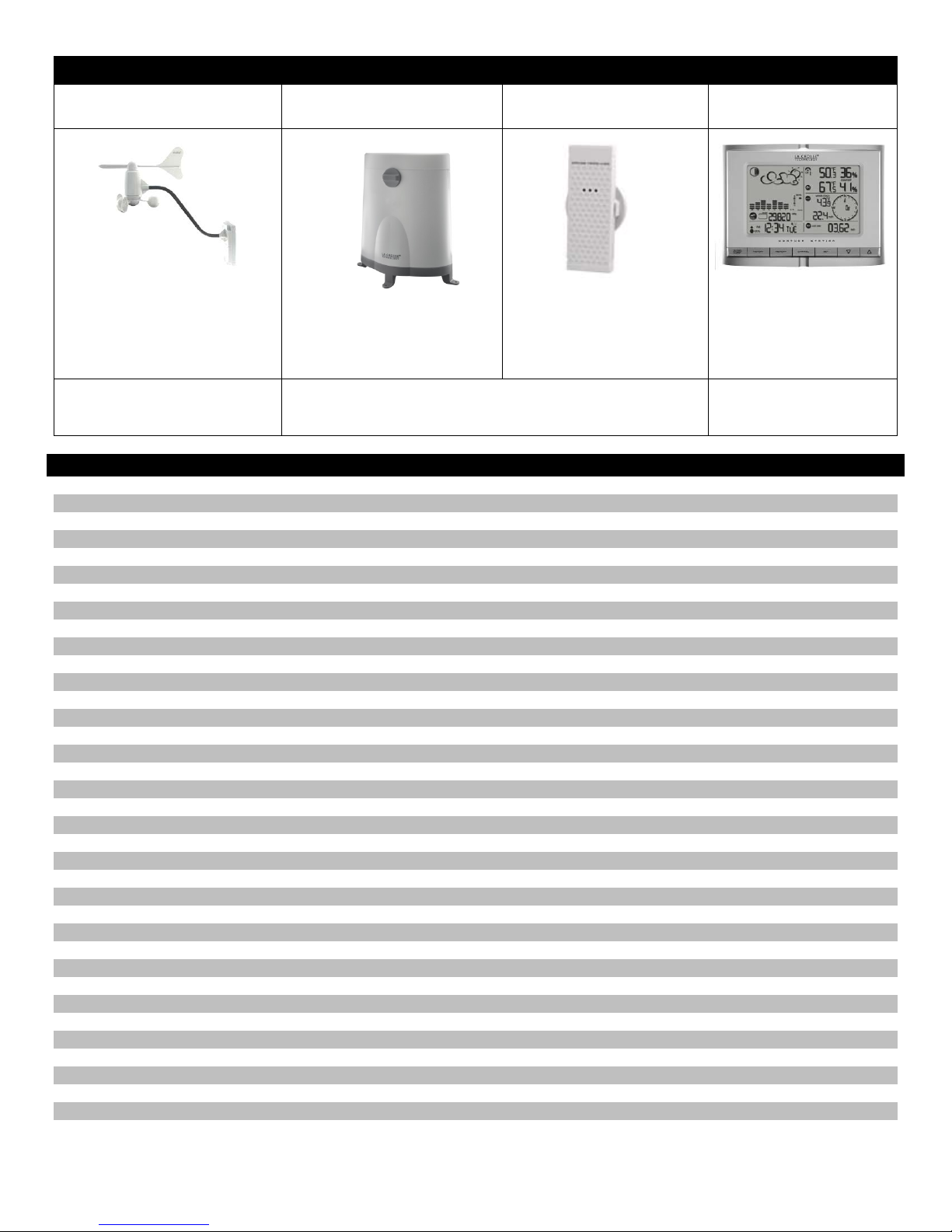
Carefully open the package and check that the follow ing conten ts are complete :
Wind Sensor
TS805
Rain Sensor
TS906
Thermo-Hygro Sensor
TS21
Wireless Display
WS-1517
Wind Sens or a lso Pr o tec ted und er
All items, including Wind Sensor, are Protected under U.S. Patents:
• Requires 4 mounting screws
• Requir es 2-AA batteri es (n ot
included)
• 1 hex key wrench
• Requires 4 mounting screws
• Requir es 2-AA batteri es (n ot
included)
• Wall mount adapter
• Requir es 2-AAA bat teri es
(not included)
• 7.5 V AC/DC adapter
(included)
• 4-AA ba t teries
(not included)
U.S. Patent: 6,761,065; RE42,057
5,978,738; 6,076,044; & 6,597,990
Table of Contents
Contents 2
Features 3
Setup Instructi ons St ep-by-Step 3
LCD Screen 6
Buttons 6
Program Menu 6
Language 6
City Code (Time Zone) 6
Set Calendar 7
Set Time 7
Custom Settings 7
Clock and Alarm Window 7
WWVB Radio-Controlled Time Signal 8
Manual Signal Search 8
Time Alarm 8
Alarm/Snooze Set 8
Activate/Deactivate Alarm 9
Snooze Function 9
Pressure and Weather Window 9
Pressure and Altitude Information 9
Local-Change or Set Altitude 10
Sea Level Pressure-Change or Set 10
View History Graph: Pressure, Temperature, Humidity 10
Weather Forecast Icons 10
Moon Phase 11
View Moon P hase Hi stor y 11
Temperature and Humidity Window 12
Channel Indic ator 12
Remote Sensor Status Ic on 12
Search for Remote Sensors 12
View Temperature or Dew Point 12
Select Fahrenheit or Celsius 13
Set Te mperature Alarms 13
Disable Te mperature Alarms 13
MAX/MIN Records 13
Comfort Level Stat em ent 13
2

Rain Window 13
Rain Statistic s 14
Select Rain Display : inches or mm 14
24 Hour Rainfall Alert 14
Wind Window 14
Wind Display 15
Wind Directi on 15
Wind Speed, Wind Gust, Wind Chill 15
Select Wind Speed Unit of Measure: km/ h, mph, m/s, k n o ts 15
Wind MAX/MIN Data 15
Set Wind Alerts 15
Disable Wind Alerts 16
Backlight Options 16
Memory Reset Procedure 16
Changing Batteri es 16
Weather Station 16
Remote Sensors 17
Position Sensors Out si de 17
Wind 18
Rain 18
Thermo-hygro 18
Position Weather Station 18
Care and Maintenance 19
Specifications 19
Warranty Information 20
FCC Statement 21
City Codes 22
Features
• Moon phase icon
• Forecast icons change based on Barometric Pressure
• Barometric Pr essure with 24 hr. history graph
• Local Barometric Pressure reading
• 12/24 hr. atomi c tim e and date with manual set option
• Outdoor temper ature (°F/°C)
• Outdoor humidity ( %RH)
• Indoor temperat ur e (°F/ ° C)
• Indoor humidit y (%RH)
• Wind chill (°F/°C)
• Wind speed (mph, m/s, km/h, knots)
• Wind directi on compass display
• Rainfall am ount (inc hes/m m )
• Time alarm with snooze (weekly and single day settings)
• Calendar display : M/D or D/M in six languages
• Altitude adjustm ent for pressure compensation
• Dew point and comfort level indicators
• Low battery indi c ators
• Light sensor detects low light conditions and automatically adjusts backli ght
• Wireless range of 100 feet (30 meters) open air
Setup Instructions Step-by-Step
Batteries: We recomm end usi ng Alkaline batteri es for the remote sensors and the weather station when temperatures are
above 32°F (0°C). We recommend using Lit hium batt eri es for the remote sensors when temperat ur es are below 32°F
(0°C).
Note: Setup all three remote sensors and allow them to run for at least two minute s before powering the weather
station. Ensure all sensor readings are received on the weather station befor e m ounting sensors outside.
3
STEP 1: Complete the initial setup on a table with all com ponents within 10 feet of each other. This allows all the sensors
to connect repeat edly with the weather station duri ng setup to lock the si gnal.
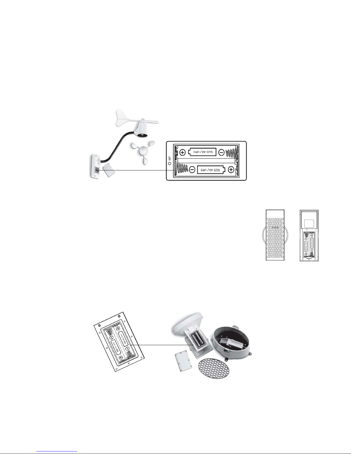
STEP 2: Win d
Wind Cups
1. The wind cups are held on with a set screw. Use a flashlight to look i nto t he m ounting hole of the wind cups. Check
that the set screw is not obstructing the opening.
2. Look at the axle shaft of the wind sensor. Notice that one side of the axle shaft is flat.
3. P lace the wind cups over the axle shaf t of the wind sensor and gently slide them into plac e.
4. The set screw should connect with the flat side of the axle shaft to prevent slipping.
5. Use the hex key wrench tool provided to tighten the small set screw inside the cups.
6. Test to assure the wind cups are securely mounted on the anem om eter shaft and spin freely
Battery instal lation
1. Remove four (4) screws from the bat tery compartment of the wind sensor. Be careful not to drop them.
2. Open the battery compartment and install two (2) AA size Alkaline batteries (not included) matchi ng the polarities
shown.
3. Replace the battery c om partm ent door and secure the screws.
STEP 3: Thermo-hygro
1. S lide the battery cov er down and lift off the back of the thermo-hygro sensor.
2. Install two (2) AAA size Alkaline batteries (not included) mat c hing the polarities shown in
the battery compartment.
3. Replace the battery c om partm ent door.
STEP 4: Rain
1. Unlock the funnel-shaped top on the rain sensor by tur ning both knobs on the sides in a counter-clockwise direction.
2. Lift the funnel-shaped top off the rain sensor bucket .
3. Remove seven (7) small screws from the bat tery compartment cover.
4. Insert two (2) AA size Alkaline bat teries (not included), matching the polarities as shown in the battery compartment.
5. Replace the battery c om partm ent door and secure the screws.
6. Insert the funnel-shaped top into the rain sensor bucket. Turn the knobs clockwise to secure it.
Allow all sensors to operat e for two minutes before starting the weath er st at io n.
IMPORTANT: Make sure to observe the correct polarity when inserting batteries (not incl uded) . The
+ markings on the
batteries must line up with the diagrams inside the battery c om par tments. Inserting the batteries incorrectly may
4
result in permanen t damage to the w eather st at io n. During the setup process, place t he wir eless display and the
Flashes 5-15 minutes during setup
outdoor sensors on a surfac e with 5-10 feet between each sensor and the display.
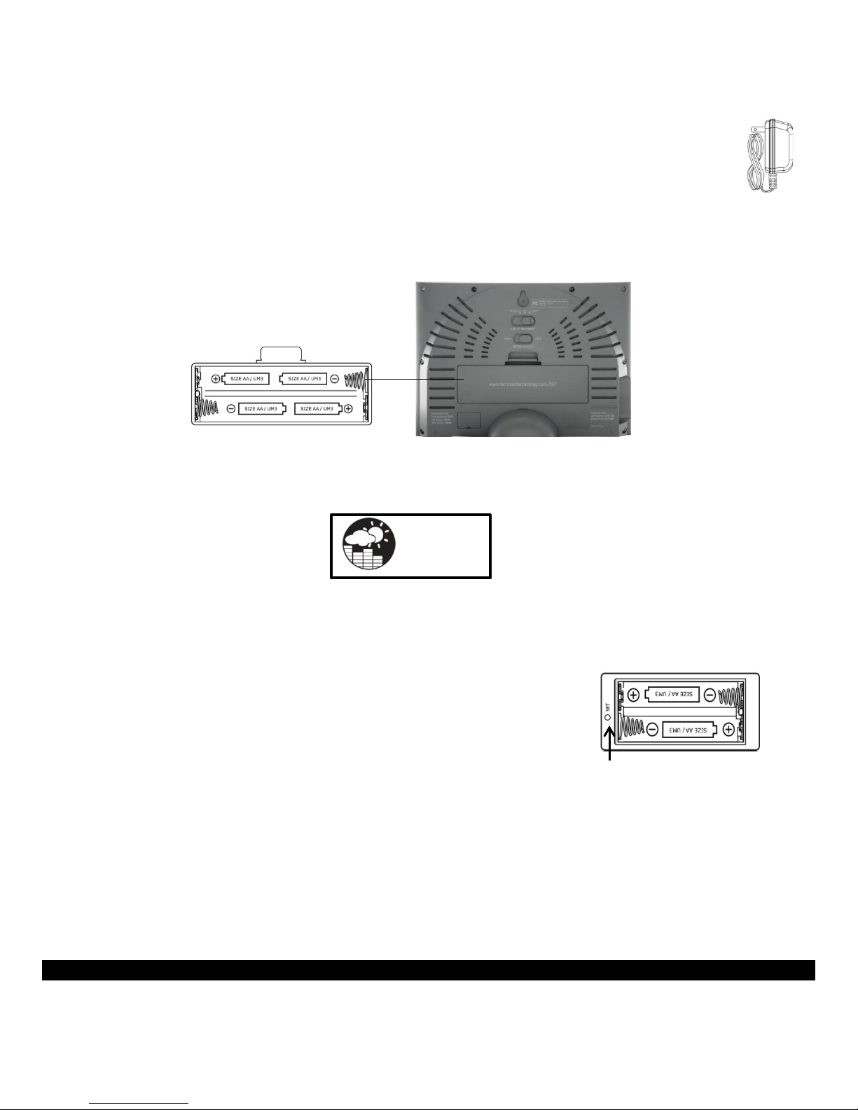
STEP 5: Weather Station
1. Connec t 7.5 V A/C adapter provided, to the weather station and plug int o to t he wall power outlet.
Note: The A/C adaptor connection is required for automatic backlight control to function. When the
weather station oper ates on battery power alone, the auto backlight control function is disabled.
2. Connec t the table stand to the back of weather station to place on a table or other hori z ontal surface.
Optiona l ba tt e r y ope r a tion:
3. S lide the battery cov er tab down and pull out to open the battery compartment on t he bac k of the weather stat ion.
4. Insert four (4) AA size Alkaline batteries according to the pol ar ities shown and replace the batter y c om partm ent door,
(optional).
5. Once the weather stati on is powered, the display will show all avail able LCD segments for a moment.
IMPORTANT: Do not press any buttons during the setup process which takes 5-15 minutes. During this time the weather
station will flash the pressure and weather icon and inHg (inches of mercury) . Setup is completed when the weather
station shows defaul t settings for pressure and altitude (sea level), i ndoor /outdoor temperature and humi dity, wind and
rain readings, etc.
InHg
STEP 6:
Set Wind Direction
1. Wait until all the sensor readings are received by the weather station.
2. M anually point the wind direc tion vane to the North (use a compass or map if necessary).
3. P r ess the SET opening loc ated inside battery compartment with a paper clip or similar tool. This will set the l ocal wind
direction t o North.
Only press once. Continued presses of the SET opening, toggles the wind
direction bet ween the f ac tory defaults preset or manual set dir ec tion.
Note: Repeat t his procedur e every time when changing the batt eri es.
4. Watch f or the nex t updat e to ensure the direction changed to Nort h.
Step 7: Program the weather station. See “Program Menu” below.
Note: This weather station has been desi gned to work right out of the box 10-15 minutes after setup.
Language and City Code are t he only required items to set in the program menu. When the WWVB radio-controlled time
signal is received, the time and date will be set according to city code selected.
There are additi onal oper ational details and suggestions for custom settings and alarms including:
• The time alarms
• The temperatur e aler ts
• Daily rainfall alerts
• Wind alerts
• Local Pressure
See “Custom Settings” for details on these optional setti ngs.
LCD Screen
5
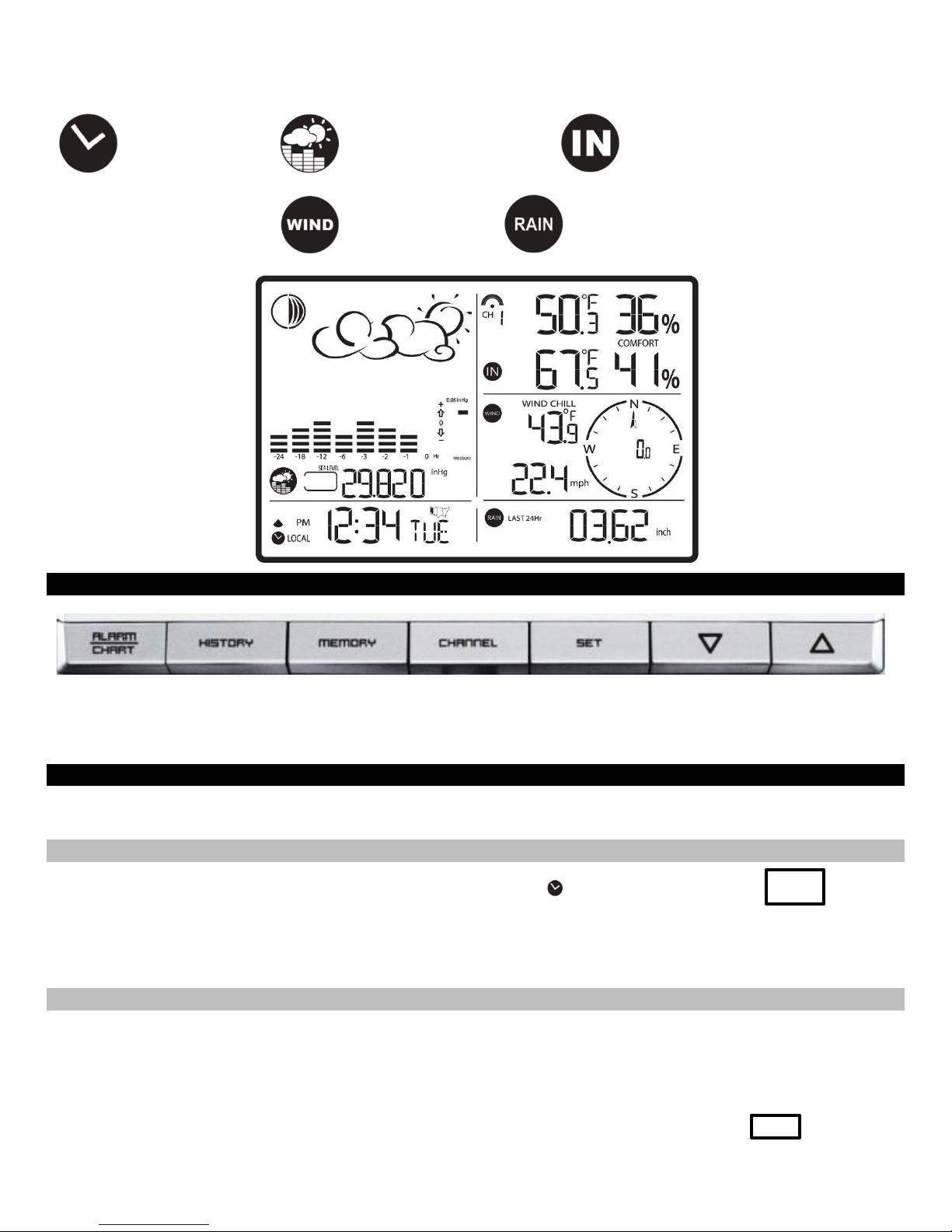
The LCD screen illustr ates the five programmable sections of the display. Each section will flash an icon while active and
available t o hav e feat ur es programmed.
Clock and Alarm icon Pressure and Weather icon Tem per ature and Humidity icon
Wind icon Rain icon
Buttons
Note: This weather station has a channel button and the abi lity to read additional out door sensors. La Cros se
Technology
®
does not plan to sell these addit ional outdoor temperatur e and humi dity sensors. Therefore the CHANNEL
button has no function on this weather station. The TS21 thermo-hygro sensor does not read to other channels.
Program Menu
The SET button will move through the pr ogr am menu. The UP or DOWN arrow buttons will change a value.
Language
1. Pr ess the UP or DOW N arrow button until the clock and alarm ic on flashes. ENG
2. Hold SET button until the day of week language abbreviation ENG will flash.
3. P r ess the UP or DOWN arr ow butt on to select the desired language for day of the week in English (ENG.), German
(GER.), French (FRE.), Italian (ITA.), Spanish (SPA.) or Dutch (DUT.).
4. P r ess the SET but ton to confirm and move to select the city code for your time zone.
City Code (Time Zone)
There is a list of City Codes at the end of t his book. A map of the USA will appear when Pacific, Mountain, Central or
Eastern time zones are select ed.
1. The default city code, LAX (Los Angeles) will flash. Use the UP and DOWN buttons to select the desir ed city code for
your time zone.
2. Refer to table in the back of this manual f or a list of available cities. LAX
6
3. P r ess the SET but ton to confirm the city selecti on and m ov e to calendar settings.
Note: You can stop here and allow the radio-controlled time signal from the atomic clock in Ft. Collins, Colorado to set
the time and date.
Calendar Setti ngs
1. The year will flash. Press the UP or DOWN button to select the cor r ect y ear. Press the SET button to confirm year
selection and move to the month.
2. The month will flash. Press the UP or DOWN button to select the correct month. Pr ess the SET button to confirm
selection and move to the date.
3. The numeric date will flash. Pr ess the UP or DOWN button t o select the cor r ec t dat e. Pr ess the SET button to confirm
selection and move to the date format.
4. The date format will flash. Press the UP or DOWN button to select the correct format of month and date (M/D or
D/M). Press the SET button to confirm selection and move to time settings.
Time Settings
1. 12H will flash. Press the UP or DOWN button to select either 12 hour (AM/PM) or 24 hour time (24:00) format. Press
the SET button to confirm selecti on and move to the hour.
2. The hour will flash. Press the UP or DOWN button to select the correct hour. Press the SET button to confirm
selection and move to the minutes.
3. The minutes will flash. Press the UP or DOWN button to select the correct minute. Press the SET button to confirm
selection and t o complete the initial programming f or your weather station.
Note: If you do not complet e this sequence your entries will be lost.
Note: Hold the SET button at any time during the programming to return to normal clock and al arm window. All previous
settings will be cancelled.
After programming is completed, the weather stati on will show the default clock and alarm window.
Custom Settings
You weather stat ion will function without additional sett ings. These cu stom settings all ow more det ailed settings and alerts
in each section of the weather station. For each custom setting the “window icon” for that section must be flashing for a
change to be made. We will take each section individually.
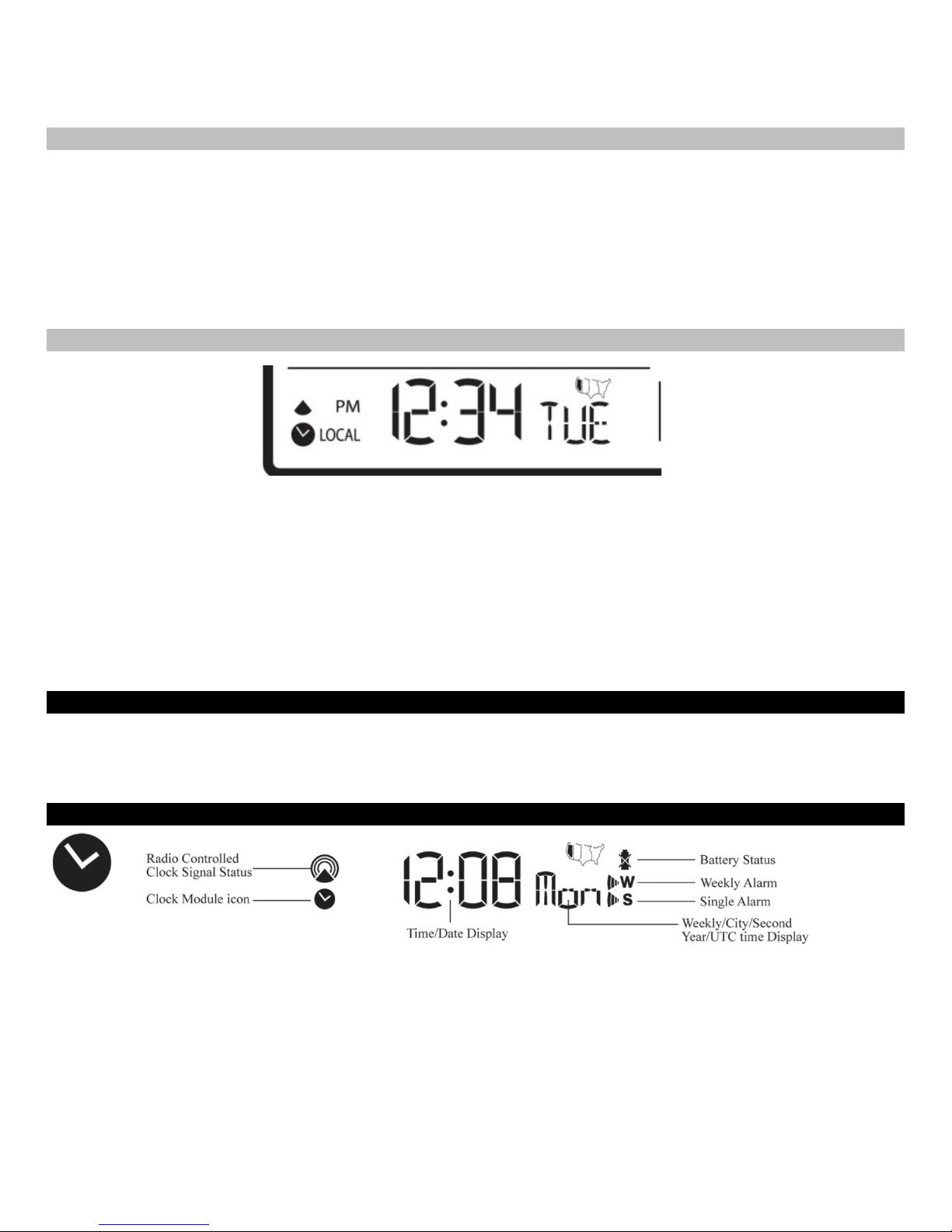
Clock and Alarm Window
The standard clock and alarm section provides the WWVB signal str ength, battery status of the weather stat ion (when
operating on batteries only), and alarm active symbols.
There are options to di spl ay :
• Time and Weekday
• Time and City Code
• Time and Seconds
• Month/Day/Year or Day/ Month/ Y ear
• Current UTC (Univer sal Coor dinated Time Simply press and release the SET button to change the display of the
weather station (when the clock and alarm icon is flashing)
7
 Loading...