

Page 1
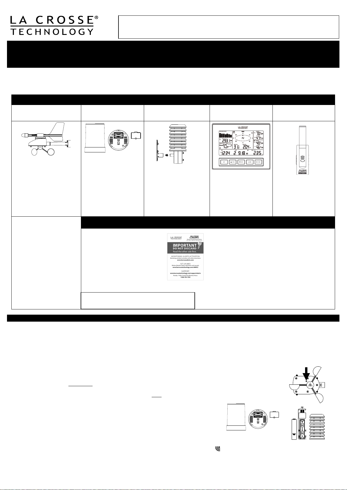
CAREFULLY OPEN THE PACKAGE AND LOCATE THE FOLLOWING CONTENTS:
Wireless Solar Powered
Wind Sensor TX63U-IT
Wireless Self-Emptying
Rain Sensor TX58UN-IT
Wireless Thermo-Hygro
Sensor TX59UN-1-IT
Wireless Weather
Station C84612
La Crosse Alerts
Gateway Set (Optional)
Connects your network
to Gateway
Remote Monitoring & Alerts Account Activation Card
Remote Monitoring & Text/E-mail Alerts
IMPORTANT!!
• Optional Remote Monitoring & Text/E-m ail Alerts are
monitoring & alerts required (n ot inc l uded)
Press Reset Button on
Light)
Once you have set up the Wireless Weather St ation with this guide, if you w is h to ac ti vate the opt i onal
OPTIONAL FEATURES
remote m onitorin g and alerts features, visit www.lacrossealerts.com to create a personal account
and follow the easy, step-by-step online instructions to guide you t hr o ugh acti vat i on.
Wireless Weather Station
Monitor home & backyard weather with the stand-alone Wireless Weather Station,
or use included remote monitoring & alerts on your smartphone, tablet or computer.*
Model C84612 | Hardware Quick Setup Gu ide
The Wireless Weather Station information and full manual ar e av ail able at: www.lacrossetechnology.com/c84612. The syst em w orks as a stand-alone
W eather St at i on or a R em ot e Monitori ng Weather Station when using the included La Crosse Alerts Gateway*. There is no app. or software to install.
All remot e m on it or in g is don e on w w w. l acr os sealer ts .com with an acc ou nt th at you create if you wish to use these added features.*
1. Mast hold er
2. Right an gl e ad apt or
3. 1 x U-bolts
4. 2 Washers + 2 Nuts
5. Plastic Reset Rod
6. 100% solar-powered
All items, includ ing W ind
Sensor, ar e Pro tec ted und er
U.S. Patents: 5,978,738;
6,07 6,044; & 6,597,990
Wind Sens or a lso Pr o tec ted
under U.S. Patent: 6,761,065;
RE42,057
1. Base sensor,
funnel top cover
and battery cover
(pre-assembled)
2. Requires two “AA”
Alkaline batteries
(included)
1. Airflow cover
2. Wall mount adapter
3. Mounting screws
4. Plastic anchors for
5. Requires two “C”
Do Not Discard Card:
Contains the Activation Key to enable
remote monit or in g and alerts on
www.lacrossealerts.com. Please file
for your future r ec or ds if you d o not
wish to use the Internet connected
features at this time.
screws
Alkaline batteries
(included)
1. Foldout stand
2. Requires three “C”
Alkaline batteries
3. (included)
included to rem otely monitor your home & bac k yard
weather on w ww .l acrossealerts .com fr om your
smartphone, tablet or computer.*
• Set & receive custom e-mail & text alerts:*
• Outdoor temperature & humidity
• Wind & rain
• Baromet ric pressure
• Indoor temperature & humidity
• High-speed Internet access, network router &
Internet-enab l ed device with web browser required
(not include d)
• E-mail account and / or SM S t ext abi lity for remote
1. Gateway
2. 20-volt A/C Adapter
3. Ethernet (LAN) cable;
router with high-speed
Internet (not included)
SETUP INSTRUCTIONS STEP BY STEP
IMPORTANT: Make sure to observe the correct polarity when inserting batteries. The "+" markings on the batteries must line up with the diagrams inside the
battery compartments. Inserting the batteries incorrectly may result in permanent damage to the units. During the initial set u p process, pl ace the
wireless weather station and the outdoor sensors on a surface with 5-10 feet between each sensor and the weather station. Only use Alk alin e batteries,
rechargeable batteries may not work:
STEP 1: Complete initi al s et u p on a tab le with all c omp onents wit hi n 10 f eet of each other .
STEP 2:
• It is important to allow sufficient light to reach the solar panel while activating the wind sensor. Mak e sur e the lights ar e on in the
setup room and the solar panel is facing a 60W light bulb or brighter.
• Ensure the solar panel is not covered, and then remove the black protective foil on the solar panel. Remove the tape covering
the reset hole.
• Use the provided plastic reset rod to gently press the reset button once in the hole on the bottom of the sensor.
STEP 3: Insert two "AA" size batteries into rain sensor with correct polarity.
STEP 4:
• Insert two "C" size batteries into the thermo-hygro sensor with the correct polarity.
Note: Allow all sensors to run for two minute s before inserting batteries in the weather station.
STEP 5:
• Insert three "C" size batteries into the wireless weather station with the cor rect polarity.
• Note: Every time the wireless weather station receives data from the sensors, the wireless icons will blink once and then return to solid if the last
transmission was successful. A wind speed or rainfall amount that reads "0" does not mean reception failure. It means that there was no wi n d or rain at the
time of the last measurement. The thermo-hygro sensor syncs with the wind and rain sensors and sends all outdoor sensor data to the weather station. The
thermo-hygro sensor tries for 4 minutes to sync to the wind sensor and then 4 minutes for the rain sensor. If not successful within 4 minutes, the thermohygro sensor will stop looking for the other sensors.
Bottom of Wind Sensor
(Solar Panel Must Face
1
Page 2
• Wait 10 minutes for reception from all sensors before setting time and date or mounting sensors outside.
STEP 6: Set Time and Date. See “Program Menu” below.
Setup Troubleshooting: If the sensor data fails to display for any of the outdoor sensors within 10 minutes, (“- - -“are displayed), remove the batteries from
all units f or 1 mi nu t e and st ar t the Setup proced ur e again at Step 1.
Weather Station Program Menu
There are 5 function buttons located on the unit: SET, ▲/DATE, ▼/RAIN, ALARM, an d MIN /MAX. The SET button mov es throug h th e pr o gram menu. Press
and release the ▲/DATE or ▼/RAIN button to change a value. Save c h ang es and exit th e program m en u at an y point by pr ess in g t h e MIN/MAX b utt on.
• CONTRAST: Press and h old th e SET butt on. LCD and a number from 1-8 will flash. Press and r eleas e the ▲/DATE or ▼/RAIN button to adjust the
Contrast of the LCD. Press and release the SET button to confirm and continue.
• HOUR: The Hour will flash. Pr ess and release the ▲/DATE or ▼/RAIN button until the correct Hour is shown. Press and r elease the SET button to confirm
and continue.
Note: When in 12h mode, there is only a 'PM' display, which appears under the word TIME. During the 'AM' hours this area w i ll be blank.
• MINUTES: The Minutes will flash. Press and releas e the ▲ /DATE or ▼/RAIN button until the corr ect Minutes are displayed. Press and release the SET
button to confirm and continue.
• 12/24-HOUR TIME: 12h or 24h will flash. To change between 12h and 24h, press and release the ▲/DATE or ▼/RAIN button. Press and releas e the SET
button to confirm and continue.
Note: Whe n in 24-hour time th e dat e wi ll dis pl ay Day first, th en M on th.
• YEAR: The Year will flash. Press and release the ▲/DATE or ▼/RAIN button to set the c orrect Year. Press and release the SET button to confirm and
continue.
• MONTH: The Month will flash. Press and release the ▲/DATE or ▼/RAIN button to set correct Month. Press and release the SET button to confirm and
continue.
• DATE: The Date will flash. Pr ess and release the ▲/DATE or ▼/RAI N button to set the correct Date. Press and release the SET button to confirm and
continue.
• FAHRENHEIT/CELSIUS: °F will flash in the wind chill, indoor temperature and outd oor temperature areas. Press and release the ▲/DATE or ▼/RAIN
button to select between Fahrenheit and Celsius. Press and release the SET button to confirm and continue.
• WIND SPEED UNIT: Wind Speed unit MPH will flash. Press and release the ▲/DATE or ▼/RAIN button to s elect from mph, m/s, knots, Beaufort, or km/h.
Press and release the SET button to confirm and continue.
• RAIN UNIT: Rainfall Inches will flash. Press and releas e the ▲/DATE or ▼/RAIN button to select in or mm. Press and release the SET button to confirm
and continue.
• PRESSURE UNIT: The Air Pressure unit inHg will flash. Press the ▲/DATE or ▼/RAIN button to select inHg or hPa. The default setting is inHg. Press and
release the SET button to confirm and continue.
• RELATIVE PRESSURE SETTING: The Relativ e Air Pre ssur e will flash. Press the ▲/DATE or ▼/RAIN button to adjust the Relative Air Pressure. Press
and release the SET button to confirm and continue.
Note: Refer to you r l oc al w eat h er reporting station for an appropriate setting. It is important that this setting be adjusted for local conditions to ensure
forecast acc u ra cy.
• FORECAST SENSITIVITY: The Forecast Sensitivity will flash. The default sett ing of .09 works w ell in mos t areas of th e cou ntry, how ev e r in ar eas w ith
relatively constant pressure this should be set to .06, (within 30 miles of the coast) and in areas with significant pressure changes this should be set to 0.12
(within 30 miles of the desert). Press the ▲/DATE or ▼/R AIN button to adjust. Press and release the SET button to confirm and continue.
• STORM ALARM SENSITIVTY: The Storm Alarm Sensitivity will flash. The default setting of .15 works wel l in m ost ar eas , h owever you m ay n eed to
adjust this level up or down depending on your local conditions. Us e the ▲/DATE or ▼/RAIN button to adjust. Pr ess and release the SET button to confirm
and continue.
• STORM ALARM: AON or AOFF will flash. This will turn the Storm Alarm ON or OFF. Use the ▲/DATE or ▼/RAIN button to toggle the Storm Alarm ON
(AON) and OFF (AOFF). Press and release the SET button to confirm and continue.
• WIND DIRECTION DISPLAY: The Dash in the wind compass will flash. Us e the ▲/DATE or ▼/RAIN button to select the Wind Direction to be shown in
degrees (dash) or letters NNW. Press and release the SET button to confirm and continue.
• FACTORY RESET: Res off will be displayed. Us e the ▲/DATE or ▼/RAIN button to select:
o Res LO to reset the Internet connection only (all weather station readings remain unchanged) Weather station will need to be re-registered.
o Res ALL only if you wish to Factory Reset the Weather Center.
o Res OFF If you do not wish to restart the weather center, bu t were only changing settings (time date etc.).
o Press and release the SET button to complete the program menu.
Note: To Factory Reset the weather center, select Res on and press the SET button to confirm. The station will begin to count down numbers in the date
area. When it is complete it will say Done. Then remove the batteries and follow the Restart up procedure.
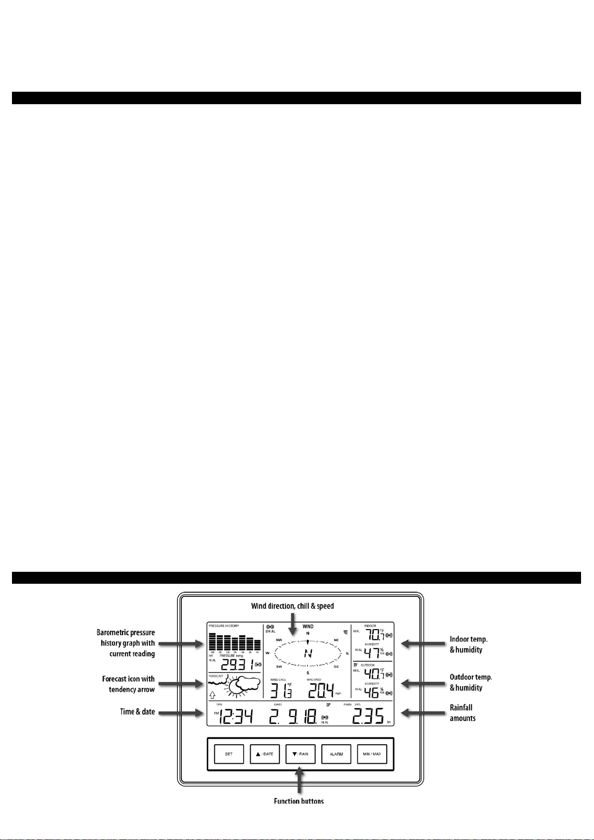
Weather Station LCD Overview
2
Page 3
Weather Station Display Modes
Press and release the SET button to toggle between the display of Mode 1 or Mode 2:
MODE 1: Wind Speed MODE 2: Wind Gust
24 hr. Pressure History Graph 72 hr. Pressure History Graph
Other But t ons Pr ovi d e Multipl e Fu nc t i ons
▲/DATE:
• Press and release to switch between Date and Seconds display.
• Press and hold until the station beeps to search for remote sensors.
▼/RAIN:
• Press and release to view 1-hour, 24-hour, 1-week, 1-month or Total Rainfall.
• Press and hold to sync the weather station with the gateway.
Rain Display
For all measurements, it is important time and date are set correctly on your w eat her station .
• 1-HOUR RAIN: The 1-hour rain reflects rain that has fallen from current time and back 1-hour. It updates ev er y four minut es (1 5 m eas ur ements ). T h e hour
is not a fixed clock time measurement. It is literally an ongoing “last 60 minutes” timer.
• 24-HOUR RAIN: T he 24-hour rain reflects the rain that has fallen from current time and back 24-hou r s . This is not a midni gh t to midnig ht m eas urement .
The day is not a fixed clock time measurement. It is literally an ongoing “last 24 hours” timer.
• WEEKLY RAIN: The amou nt of rainf all of th e pr evi ou s w eek . Week: Rain tot al f or th e week is r es et every 7 days. W eek b egi ns 1 day befo r e th e day th e
batter i es ar e f irs t ins er t ed into the weather st at i on. For examp l e, if the batter i es are insert ed on a Thursd ay, the start of the weekly totals will be Wednesday
of each week .
• MONTHLY RAIN: Monthly rain reflects the previous month’s rain and will update 12AM the first day of the month.
• TOTAL RAIN: Total rain will remain until you manually reset this value. Total rain reflects the rain from time of weather station set-up until you manually
reset the total rain.
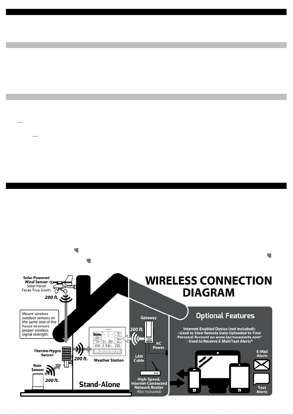
Proper Placement of Weather Station, Sensors and Opt io n al G ateway with Mounting Instructions
IMPORTANT: Ensur e th at al l of t h e s ens or data can b e rec ei ved at the int ended mounting loc at i ons b ef ore you drill m ou nting hol es . Th e outdoor sensors
have a wir el ess ran ge of 200-feet. Keep in mind that the 200-foot rang e equ ates to an op en-air sc enar i o wi th n o obs t ructions. Each obstruction (roof, walls,
floors, ceilings, etc.) will reduce the range.
The thermo-h ygr o s ensor measu res outd oor t emp erature & hu mi dity and collects th e dat a from the win d an d th e r ain s ens or s and s en ds all outdoor w e ath er
data to the wireless weather station, so the thermo-hygro sensor mus t be wi th in t h e 200-foot wireless r ang e of t h e wir el ess w eat h er st ation. This allows the
wind and rain sensors to be placed relative to the thermo-hygro sensor r ath er th an t h e wi r eles s w eat her stati on. See the Wireless Connection Diagram
below.
• The wind an d rai n s ensors must be moun t ed wi th in the 200-foot wireless range of the thermo-hygro sensor and on the same side of the house. In
additi on, 915 MHz s ensors transmit bett er at a mi ni mu m m ount heig h t of 6 feet.
• The wirel ess weather station mus t b e wit hi n the 200-foot wireless range of the gateway to upl o ad weather d at a t o the I nt ernet.
If the sensor wireless reception icons drop from the weather station as you move them into their intended locations, the sensors may be too far from the
wireless weather station. Try moving the wireless weather station or the sensors closer and wait a few minutes to see if the wireless reception icons
display again. If the wireless reception icons are still not displayed after re-posit i oni ng the sens ors or the wirel ess weather station, hold the ▲/DATE button
for 2 seconds to re-synchronize the wireless weather station with the s ensors.
3
Page 4

Wireless Self-Emptying Rain Sensor (TX58UN-IT)
The rain s ens or sh oul d b e mounted on a lev el surfac e in an op en area within t h e 200-foot wireless range of the thermo-h ygr o s ensor and on
the same side of the house. Mount the rain sensor at least 6 f eet off the ground level for optimum wireless transmission. The rain sensor should
be accessible to allow for periodic cleaning of debris or insects. Do not over tighten mounting screws. They should be snug not tight to prevent
inaccurate readings.
Wireless Solar Powered Wind Sensor (TX63U-IT)
The wind sensor must b e ins t alled with the front of the sensor (the solar panel) facing true south, or the reported wind direction
will not b e accurate. Moun t wit h in th e 200-foot wireless range of the thermo-hygro sensor and on the same side of the house at a mi ni m u m
height of 6 feet. The roof may or may not be an ideal mounting location. Secure the main unit to the shaft of the mast holder. Use the rightangle ad apt or if the wi nd s ensor will b e mounted on a horizont al m as t or surface.
Fasten the wind sensor to a suitable mast using the U-bolt, washers and nuts inc l ud ed . Note: Mount the wind sensor onto a mast so the wind
can reach the sensor unobstructed from all directions for an accurate reading. The ideal mast is between 0.62" and 1.3” in di am et er . The wind
sensor DOES NOT have replaceable batteries - it consumes solar power and charges the internal battery pack automatically.
Wireless Thermo-Hygro (Sensor TX59UN-1-IT)
The thermo-h ygr o s ensor is "w eat h er r esis tant", but n ot " w at er pr oof". To ens ur e an extend ed lif e of your sens or, m ount it in a semicovered
place out of the element s . Minimum height is 6 feet; under the eaves on the North side of the house can be ideal to avoid t he effec ts of
sunlig ht. M ou nt th e s ensor 18" dow n from the ea ves to ens ure opti m um per formanc e. This w il l ass ure the tem perature of the air coming out
of the attic will not affect data collected by the sensor.
To wall mount the ther m o-hygro sensor, fix the wall holder onto the desired wall using the included screws, plug the sensor firmly into the wall
holder and replace the rain cover if it is not already in place.
Note: Af ter mounti ng the sens ors , if the weat her data is not received, press and hold the ▲/DATE button for 2 seconds to synchronize the wireless weather
station to the sensors.
Wireless Weather Station (C84612)
The Wireless Weather Station is free standing with the fold out bas e stan d or c an be w all mounted.
Wall mount:
• Fix a screw (not supplied) into the desired wall, leaving the head extended out the by about 0.2 inches (5mm).
• Hang the weather station onto the screw. Ensure that it locks into place before releasing the professional weather station.
Free standing: Si mpl y pu ll out the st and t o the b ac k of the weather s tation and pl ac e on a flat sur face.
Position:
• Choose a location 6 feet or more from electronics such as cordless phones, gaming systems, televisions, microwaves, routers,
baby monitors, etc., which can prevent signal reception.
• Place wit hi n range of the outdoor transmitters. The maximum transmitting range in open air is 200-feet (60 meters).
• Be aware of el ec t rical wires an d pl u m bin g w it hin a w all. T h is wi ll interf er e wit h si gn al r ec ept i on.
• Obstacles such as walls, windows, stucco, concrete, and large metal objects can reduce the range.
La Crosse Alerts Gateway Set (OPTIONAL: Used ONLY if you want to use the rem ote mon it ori n g an d al er t f eat ur es . )
• The Gateway should be installed indoors in an easy-to-reach location near your network router, A/C power out l et an d w it hin
range of the wireless weather station (200 feet in open space).
• After you c omp l ete t h e act i vat i on on w ww .l across eal er t s .com, you m ay mount the gateway to the w all wit h the inclu d ed
mounti ng pl ate and drywall anchors.
• Online registration requires that you press the gray button on the Gateway during setup.
Stand-Alone Weather Station OR Internet Connected Weath er S t at io n wit h Remote Monitoring & Alerts
Use the weather station as:
• (OPTION 1 ) Stand-a l on e w eather st ati o n with wir eless bac k yar d weather s ens or s . Inc lu ded Gateway Set and Activation Card is not required.
Wireless w eat her stati on inform ation and manual ar e avai l able at: www.lacrossetechnology.com/c84612
• (OPTION 2) Internet-conne ct ed weat her st ation with remote mo n it orin g and al erts uses the included Gateway Set and Activation Card to enable
the included Remote Monitoring & Text/E-mail Alert s from www .l ac ross eal ert s .com
• Remote Monitoring & Text/E-mail Ale rts are included to r em ot el y mo nitor your home & bac k yar d w eat her on www. l acrosseal er ts .com using your
smartphone, tablet or computer.*
• Set & receive custom e-mail & text alerts for:*
• High-speed Internet access, network router & Internet-enabl ed d evice with web browser required (not included)
• E-mail account and / or SMS text ability for remote monitoring & alerts required (not inc l ud ed)
• Connect the gateway to your router (not included) with the LAN cable, for wireless connection to the weather station.
Note: See the included Activation Card for the activation key to enabl e rem ote monit ori ng and alerts . * There is no ap p. or software to install.
All remot e m on it or in g is don e on w w w. l acr os sealer ts .com with an acc ou nt th at you create if you wish to use these added features.*
• High/Low: Pressure, Indoor Temperature, Indoor Humidity,
• Outdoor temperature & humidity
• Wind & rain
• Baromet ric pressure
• Indoor temperature & humidity
Weather Station Features 14 Alarms
Outdoor Temperature and Outdoor Humidity
• High: Wind Gust
• Wind Direction
4
Page 5
• 24-hour Rainfa ll • Storm Warning Alarm
Each MIN and MAX value must be res et independently.
6
Set Alarms
1. From the normal time display mode, press and release the ALARM button repeatedly, until you see the alarm value you wish to set.
2. Hold the SET button for 2 seconds and the selected value will flash.
3. Press and releas e the ▲UP ARROW button or ▼DOWN ARROW button to set the alarm value.
4. Note: Hold an arrow button in to change the alarm value faster.
5. Press the ALARM button to confirm the value set. The digit will stop flashing. Repeat these steps with each alarm value you wish to set.
Activate/Deactivate Alarms
1. Press and r el ease the ALA R M butt on until you s ee th e alarm valu e to activate/ d eac tivat e.
2. Press the SET button to switch the Alarm On or Off.
3. The alarm icon next to the value indicates the alarm is switched ON.
Storm Alarm
There is a Storm Warning Alarm in the pr ogram men u th at c an be t ur n ed on ( AO N ) or off (AO FF) .
1. Hold the SET button to ent er the program men u. LCD and a nu mb er wi ll flash on the b ottom of the dis pl a y.
2. Press and r el ease the SET but t on 1 3 m or e tim es and you r wi ll s ee a d ow n arrow and a num b er from 0.09 t o 0.27 f l ashi n g. T his is the Storm Alarm
sensitivity (how many hPa the pressure falls before an alarm sounds). Use the ARROW buttons to select the setting desired.
3. Press and r el ease the SET but t on an d A OF F or A O N wi ll s h ow. Use the ARROW button t o tur n th e alarm on (AON ) or off (AOFF) . R el ease all buttons
and allow the display to come back to a normal display. This will take about 15 seconds.
MI N/ MAX Da ta
The weat h er station will automatically rec or d th e maximum an d mi nimum valu e of th e various weather dat a wit h time and d ate of r ecordin g.
View MIN/MAX data Reset MIN/MAX Data
Press th e MIN /MAX button to view:
• MIN/MAX Indoor Temperature
• MIN/MAX Indoor Humidity
• MIN/MAX Outdoor Temperature
• MIN/MAX Dew Point Temperature
• MIN/MAX Outdoor Humidity
• MAX Wind Gust
• Total Rainfall
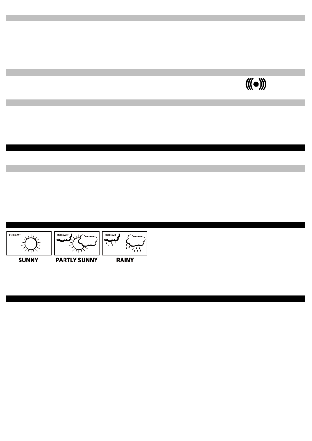
Weather Forecast Icons
chang ed or the change has been too s m all f or th e w eat h er st ation to regis ter.
W orking t og eth er wit h the w eat her icons ar e t h e weather tendency indicat ors ( arrows loc at ed on t h e left and right sid es of th e weat h er icons). When the
indicator points upwards, it means that the air-pr es s ure is incr eas in g an d t h e we ath er i s exp ec t ed to im prove, bu t wh en t h e indicator poi nt s dow n w ards, the air
-pressur e is droppi ng an d the weather is expec t ed t o b ec om e wor se.
Wireless Weather Station (C84612)
Wireless Solar-Powered Wind Sensor (TX63U-IT)
SPECIFICATIONS
• (Option 1) Works as a stand-alone Weather Station with
manual s et tim e or (O pt i on 2) W or ks as a Rem ote Monit ori ng
Weather Station with Alerts and Internet time/date sync when
using the included gateway set
• Indoor Temp.: 41°F to 104°F (5°C to 40°C)
• Indoor Humidity: 3% to 99% RH
• Wind Chill: down to -40°F (-40°C)
• Pressure (inHg/hPa): Preset range 27.10 to 31.90 inHg
• Stores over 1750 weather records in 15 min. to 2 hr. intervals
• 3 "C" Alkaline batteries (included)
• 200 ft. wireless range
• 8.665" L x 1. 59 4" W 6.795" H (22 0.1 x 40.5 x 17 2.6 mm)
• 100% solar-powered
(built-in power cell , no batteries necessary)
• Wind sp eed: 0 t o 111. 8 mp h
(km/h, m/s, knots & Beaufort scale)
• High-effici enc y s olar p anels maintain op er at i on in e very seas on
• 200 ft. wireless range
• 9.84" L x 5.74" W x 7.57" H (250 x 145.9 x 192.3 mm)
withou t m ount ing base
• Press and release the MIN/MAX button to show the
desired Min or Max values t o be reset.
• Press ▲/DATE button. The stored value will be
reset t o the c urr ent value a nd curren t time.
The weat h er f orecast ic ons in dicat e pressure tr ends in th e n ext 12 hours not
what you s ee out you r w in d ow . E ver y time a new av erage pressure valu e has
been obtained (once per minute); this v al ue is compared with an int ernal
refer ence value. If the difference between these values is bigger than the
selected weather tendency sensitivity, the weather icon changes, either for worse
or for better. In this case, the current pressure value becomes the new weather
tendency reference. If the icons do not change, either the air pressure has not
Wireless Thermo-Hygro Sensor (TX59UN-1-IT)
• Outdoor Temp.: -40°F to 139.8°F (-40°C to 59.9°C)
• Outdoor Humidity: 3% to 99% RH
• 200 ft. ireless range
• 2 "C" Alkaline batteries (included)
• 3.13" L x 3.54" W x 7.45" H (79.4 x 89.8 x 189.3 mm)
Wirele ss Sel f -Emptying Rainfall Sensor (TX58UN-IT)
• Rainfall for last hour, 24hr., week, month & total:
0 to 393.7 inches (0 to 9999.9 mm)
• 200 ft. wireless range 2 "AA" Alkaline batteries (included)
• 5.2" DIA. x 7.2" H (131.6 DIA. x 182.7 mm)
Gateway Set for Included Remote Monitoring & Text/E-m ail Al er ts
(Optional, not needed for use as a stand-alone Weather Station)
• Gateway Set (includes Gateway, AC adapter & LAN cable)
• High-speed Internet access & network router required
(not included)
• 200 ft. wireless range to Weather Station
• Internet-enabled smartphone, tablet or computer with web
browser, E-mail account and/ or SM S text abili t y for rem ote
monitoring & alerts required (n ot inc l uded)*
Indicates Alarm is Active
5
Page 6

The comp l ete ins tructi on m anual is availabl e at:
www.lacrossetechnology.com/
Le manuel d'instruction complet est disponible
El manual d e ins tr uc c i on es completo est á disp on ib le
en:
Contact Support : 1-608-782-1610
Scan QR co d e with
Scan QR code with
WARRANTY
La Crosse Technology, Ltd provides a 1-year limit ed war r anty on this prod uc t ag ains t m anuf acturing def ec ts in m ater i als an d w or k m anship.
This limited warranty begins on the original date of purchase, is valid only on products purchased and used in North America and only to the original
purchaser of this product. To receive warranty service, the purchaser must contact La Crosse Technology, Ltd for problem determination and service
procedures. Warranty service can only be performed by a La Crosse Technology, Ltd authorized service center. The original dated bil l of s ale must be
present ed upon req u est as pr oof of purchase to La Crosse Technology, Ltd or La Crosse Technology, Ltd’s authorized service center.
La Crosse Techn ol og y, Lt d will rep air or repl ac e this product , at our o pti on and at no ch arg e as stipul at ed h erein, wit h n ew or reconditioned parts or products
if found to be defective during the limited warranty period specified above. All replaced parts and products become the property of La Crosse Technology, Ltd
and must be returned to La Crosse Technology, Ltd. Replacement parts and products assume the rem ai ning orig in al warran t y, or nin ety (90) days , w hichever
is longer. La Crosse Technology, Ltd will pay all expenses for labor and materials for all repairs covered by this warranty. If necessary repairs are not
covered by this w arrant y, or if a product is examin ed whic h is not in n eed or rep air , y ou w il l b e ch ar g ed for the rep airs or ex am in ati on. The own er m us t pay
any shipping charges incurred in getting your La Crosse Technology, Ltd product to a La Crosse Technology, Ltd authorized service center. La Crosse
Technology, Ltd will pay ground return shipping charges to the owner of the product to a USA address only.
Your La Crosse Technology, Ltd warranty covers all defects in material and workmanship with the following specified exceptions: (1) damage caused by
accident, unreasonable use or neglect (including the lack of reasonable and necessary maintenance); (2) damage occurring during shipment (claims must be
present ed to the carr i er) ; (3) d am ag e t o, or d et eri oration of , an y access ory or decorati v e surface; (4) damage resulting from failure to follow instructions
contain ed in you r owner’s m an u al; ( 5) damage r es ult ing from the perform ance of rep air s or alterati ons by someon e ot h er t h an an authorized La Crosse
Technology, Ltd authorized service center; (6) units used for other than home use (7) applications and uses that this product was not intended or (8) the
products in abilit y to r ec ei ve a si gn al du e to any source of interferenc e.. This warr anty cover s onl y ac tu al defects wi th in th e product its elf, and does not cover
the cost of installation or removal from a fixed installation, normal set-up or adjustments, claims based on misrepresentation by the seller or performance
variations resulting from installation-related circumstances.
LA CROSSE TECHNOLOGY, LTD WILL NOT ASSUME LIABILITY FOR INCIDENTAL, CONSEQUENTIAL, PUNITIVE, OR OTHER SIMILAR DAMAGES
ASSOCIATED WITH THE OPERATION OR MALFUNCTION OF THIS PRODUCT. THIS PRODUCT IS NOT TO BE USED FOR MEDICAL PURPOSES OR
FOR PUBLIC INFORMATION. THIS PRODUCT IS NOT A TOY. KEEP OUT OF CHILDREN’S REACH.
This warranty gives you specific legal rights. You may also have other rights specific to your State. Some States do not allow the exclusion of consequential
or inciden tal damages ther efore the ab ove exclusion of limitation may not apply to you.
smartphone for info
& complete manual
For warranty wor k, te chn ic al suppor t or info contact:
c84612
www.lacrossetechnology.com/c84612
www.lacrossetechnology.com/c84612
Limited 1-year Warr an ty
La Crosse Technology, Ltd
2817 Los ey Bl vd . S.
La Crosse, WI 54601
sur:
smartphone for
product registration
Product Registration:
www.lacrossetechnology.com/support/register
DISCLAIMERS
* Disclaimers: La Crosse Technology , LTD. (“La Crosse”) provides various alert and monitoring services to aid users. (1) Service providers may charge users
for alert s er vices. Stan d ar d messagin g an d data rates ap ply and will b e billed to the cus t om er’s wir el ess account. Cus t om er s may be unable to receive text
messaging or data service in some areas due to unavailability of service. (2) La Crosse shall not be liable for accuracy, usef ul n ess or avai l abi li ty of data
transmitted via the service. Users are solely responsible for damages to persons or property by service use.
FCC STATEMENT
This equipment has been tested and found to comply with the limits for a
Class B digital device, purs uant to part 15 of th e FCC Rules. T h ese limits
are designed to provide reasonable protect i on ag ai ns t h armful
interferenc e in a residenti al ins t allati on. This equ ip m ent generates uses
and can radiate radio frequency energy and, if not installed and used in
accordance with the instructions, may cause harmful interference to radio
communications. How ev er, th ere is no guar antee that in terfer ence will not
occur in a particular installation. If this equipment does cause harmful
interference to radio or television reception, which can be determined by
turning t h e equ ip m ent off and on, t h e user is encouraged to try to correct
the interferenc e by on e or m ore of th e f ol l owing measures:
• Reorient or relocate the receiving antenna.
• Increase the separation between the equipment and receiver.
• Connect t h e eq ui pm ent into an ou tlet on a circu it differ ent from that
to which the receiver is connected.
• Consult the dealer or an experienced radio/TV technician for help.
This device must not be co-locat ed or op erating in c onju nction with an y
other antenna or transmitter. Operation is subject to the following two
conditions:
(1) This d evice may n ot c ause harmf ul interf er ence, and (2) This device
must accept any interference received, including interference that may
cause undesir ed op eration.
Caution! The manufacturer is not responsible for any radio or TV
interferenc e caused by un auth or i z ed m od ific ations to t his eq ui p m ent .
Such modif ications could void t h e us er authority to oper ate the
equipment. All rig hts res erved . Th is man u al m ay n ot b e rep r oduced in
any form, even in part, or duplicated or processed using electronic,
mechani cal or chem ical proces s wit hout the wri tten permission of the
publisher. This booklet may contain err ors or mis prints . T h e inf or m ati on it
contains is regularly checked and corrections are included in subsequent
editions. We disclaim any responsibility for any technical error or printing
error, or their consequences.
All trad em arks an d patents are r ec og ni z ed.
Page 7

Printed in China.
7
 Loading...