


OPERATION MANUAL
AUTOMATIC CO2 INCUBATORS
MODEL NO. WATER-JACKETED AUTOMATIC CO2:
Models With Thermal Conductivity Sensor:
460, 460JPN, 460RH*, 460-1, 460-1CE, 462, 462-1,
462-1CE, 464, 464RH, 464-1, 464-1CE
Models With Infrared Sensor:
465, 465RH*, 465-1, 467, 467-1, 469, 469-1,
8/01
MANUAL NO. 057-588-00
REV. O
LAB-LINE
AIR-JACKETED AUTOMATIC CO
Models With Thermal Conductivity Sensor:
490, 490RH*, 490-1, 490-1CE, 492, 492-1, 492-1CE,
494, 494-1, 494-1CE
Models With Infrared Sensor:
495, 495JPN, 495RH*, 495-1, 497, 497-1, 499, 499-1
Models With Thermal Conductivity Sensor And Large Chamber Capacity:
391, 391-1, 391-2**, 391-3**
*With Relative Humidity Display
**With 3-Pen Strip Chart Recorder
DESIGNERS AND MANUFACTURERS
A SUBSIDIARY of Barnstead|Thermolyne
1999 North 15th Ave.
PHONE: (563) 556-2241 or (800) 522-5463; FAX: (563) 589-0516
, Melrose Park, IL 60160-1491 USA
2:

TABLE OF CONTENTS
2

SECTION TITLE
1 Introduction
2 Description
3 Specifications
4 Features
5 Installation
6 Operation
7 Maintenance
8 Replacement Parts
Warranty
3

BE ADVISED:
IT IS MOST IMPORTANT THAT THE USER FOLLOW INSTALLATION
INSTRUCTIONS EXACTLY AS WRITTEN. FAILURE TO DO SO IS LIKELY TO
LEAD TO IMPROPER OPERATION, ERRONEOUS CALIBRATIONS AND
POSSIBLE DAMAGE TO THE EQUIPMENT. UNDER NO CIRCUMSTANCES
SHOULD THE USER ATTEMPT OPERATION WITHOUT THIS INFORMATION.
THE FOLLOWING EQUIPMENT IS TO BE SUPPLIED BY THE USER:
• Dry CO2 gas (research grade or better).
• A dual-stage regulator for the CO2 tank.
• ¼" (6.35mm) ID Flexible tubing (appropriate length from tank to
Incubator), and connected per local codes.
• Distilled or deionized water (if humidification is desired).
• Fyrite or similar chemical-based CO2 analyzer.
BE ADVISED: INSTALLATION AND PRE-OPERATION PROCEDURE WI LL
TAKE AT LEAST 24 HOURS TO COMPLETE. DO NOT ATTEMPT TO RUSH
THE PROCESS WITH SHORT CUTS TO THE PROCEDURES DESCRIBED IN
THIS MANUAL.
4

CERTIFICATION OF DECONTAMINATION:
We cannot accept for service or credit a product that has been exposed
to or contaminated with chemically or biologically toxic or infectious substances
or subjected to radioactivity without first being certified as free from said
contamination.
Please have your Medical and/or Safety Officer sign this form certifying
that proper decontamination procedures have been followed to render the
product safe and free from hazards.
Any product forwarded to us, not accompanied by this form and a proper
Return Goods Authorization Number, will be returned to the sender. To obtain a
Return Goods Authorization Number, contact the Customer Relations
Department at (800) 522-5463.
We hereby certify that the LAB-LINE INSTRUMENTS, INC. product:
Model No. and Serial No. ,
that is being forwarded has been properly decontaminated and is free from all toxic
hazards, infectious agents, radioactivity and/or other hazards.
Company/Institution Name:
Street Address:
City: State Zip
Name (please print): Title
Signature:
Phone:
DECONTAMINATION PROCEDURE (Be Specific):
Nature of Hazard That Required Decontamination:
5

SECTION 1
6

INTRODUCTION
THANK YOU
for selecting Lab-Line Instruments for your equipment needs. For maximum value and
ease of start-up,
PLEASE PROCEED AS FOLLOWS:
• Inspect the carton and contents for shipping damage. Notify the carrier immediately
if damage is found.
• Use the Accessory Checklist when unpacking to verify that the complete unit has
been received. Do not discard packing materials until all is accounted for.
• Read this Operation Manual thoroughly before deciding upon an appropriate
location for the unit: you will want to consider, where applicable, the availability of
power, water, hook-ups, drains and other unit requirements, as well as user
convenience.
• Insist that every operator of this unit becomes familiar with the Operation Section of
this manual.
• Be sure to fill out the Warranty Registration Card and mail it in to Lab-Line
Instruments within seven (7) days after receiving the unit.
IF
after reading this manual you should have any difficulties with the installation or
operation instructions, please call:
Lab-Line Customer Relations Department
(563) 556-2241 or (800) 522-5463
ALL RIGHT RESERVED
The information contained in this manual is the exclusive property of Lab-Line Instruments, Inc., and has been provided solely to enable the users of the equipment described herein to operate and maintain such equipment. Any
other use of this information, or the reproduction or transmission of all or any portion of this manual without prior
written consent of the manufacturer is expressly prohibited. © 2001, Lab-Line Instruments, Inc.
SECTION 2
7
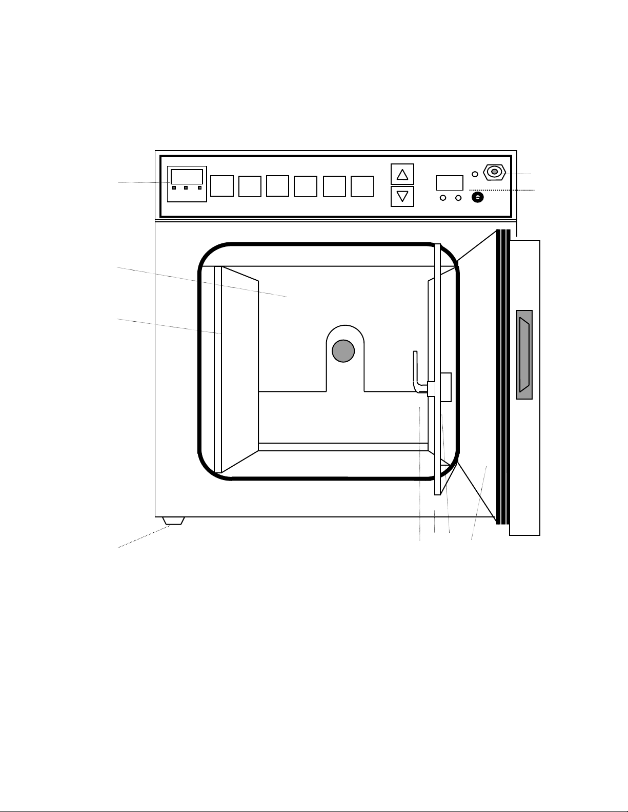
BASIC COMPONENTS, AN INITIAL OVERVIEW:
FRONT VIEW:
1
2
3
DESCRIPTION
9
10
4 567 8
1. CONTROL PANEL
2. REAR WALL COVER
3. SIDE PANEL
4. FEET, LEVELING
5. INNER GLASS DOOR
LATCH
DESCRIPTION: (Con’t)
6. INNER GLASS DOOR
7. INNER GLASS DOOR, KNOB
8. OUTER STEEL DOOR/GASKET
9. SAMPLE PORT
10. RH DISPLAY; MODELS 460RH, 490RH,
465RH, 495RH ONLY
8
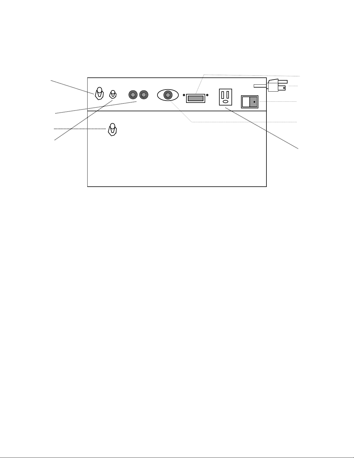
BASIC COMPONENTS, AN INITIAL OVERVIEW:
REAR VIEW
1 5
2
3
4
1. GAS INLET PORT
2. CIRCUIT BREAKERS
3. WATER OVERFLOW OUTLET (460/465 SERIES ONLY)
4. TOGGLE SWITCH FOR RH DISPLAY (460RH, 465RH, 490RH, 495RH)
5. RS232 DATA PINS CONNECTOR
6. CORDSET
7. POWER SWITCH
8. OPTIONAL ALARM RELAY OUTPUT
9. OUTLET (120 VAC UNITS ONLY)
(CON’T)
6
7
8
9
DESCRIPTION: (Con’t)
INFRARED CONTROL OF CO2
9

This sensor is impervious to relative humidity and is less susceptible to drift
and re-calibration. By measuring the absorption of infrared light within a CO2
atmosphere, the highest level of sensitivity is provided.
THERMAL-CONDUCTIVITY CONTROL OF CO2:
This sensor measures CO2 within an atmosphere by the heat of
conduction method and provides precise and reliable control.
SYSTEMS AND FEATURES:
All required operating commands are immediately accessible in a
functional format on the front of the unit and permit rapid start-up, close
monitoring and efficient control of incubation protocols.
Temperature is measured by platinum RTD (resistance temperature
detector) producing excellent control within ±0.1ºC. It is combined with the
exclusive SmartGas® algorithm method for controlling CO2 within ±0.1%. The
result is a chamber that produces excellent environmental conditions for the most
sensitive of incubations.
Air passes downward over the heated area and is then directed upward in a
gentle, uniform flow from the chamber floor. This upward draft inhibits the
contamination of cultures. If the temperature exceeds the set point by more than
the set point setting, power to the heaters is discontinued.
Audible and visual alarms alert the user of any deviation in the chamber of
temperature (±1.0°C or better) or carbon dioxide (±1.0°%). In addition, other
signals alert the user of such conditions as power failure, door ajar and low water
on water jacketed models.
To conserve gas, the CO2 solenoid valve shuts off automatically any time
the insulated, incubator door is opened. The fan motor shuts off during door
openings as well.
Required operating commands are immediately accessible in a functional
format on the front of the unit and permit rapid start-up, close monitoring and
efficient control of the incubation protocols.
To prevent unauthorized access to or alteration of command entries, a
password feature may be accessed.
Side-by-side and stacked units are available.
The crevice-free stainless steel interior is designed for easy maintenance
and prolongs useful life.
DOUBLE-DOOR CONSTRUCTION WITH INNER DOOR DEFOGGER:
A tempered glass inner door allows observation of chamber contents
without disturbing the chamber environment. Inside the steel outer door is a
heater that can defog the glass door when necessary. Each door seals to a
one-piece silicone gasket for a leak-tight environment.
SECTION 3
10

SPECIFICATIONS
ELECTRICAL REQUIREMENTS, MODEL VOLTS HZ AMPS WATTS
WATER-JACKETED MODELS:
460 120 50/60 6.3 750
460JPN* 100 50/60 7.5 750
460-1* 230/240 50/60 3.1 750
462* 120 50/60 12.5 1500
462-1* 230/240 50/60 6.3 1500
464* 120 50/60 12.5 1500
464-1* 230/240 50/60 6.3 1500
465** 120 50/60 6.3 750
465-1** 230/240 50/60 3.1 750
467** 120 50/60 12.5 1500
467-1** 230/240 50/60 6.3 1500
469** 120 50/60 12.5 1500
469-1** 230/240 50/60 6.3 1500
ELECTRICAL REQUIREMENTS,
MODEL VOLTS HZ AMPS WATTS
AIR-JACKETED MODELS:
391 120 50/60 11.3 1350
391-1 230/240 50/60 5.6 1350
391-2*** 120 50/60 11.3 1350
391-3*** 230/240 50/60 5.6 1350
490* 120 50/60 7.1 850
490-1* 230/240 50/60 3.5 850
492* 120 50/60 14.2 1700
492-1* 230/240 50/60 7.1 1700
494* 120 50/60 14.2 1700
494-1* 230/240 50/60 7.1 1700
495** 120 50/60 7.1 850
495JPN**100 50/60 8.5 850
495-1** 230/240 50/60 3.5 850
497** 120 50/60 14.2 1700
497-1** 230/240 50/60 7.1 1700
499** 120 50/60 14.2 1700
499-1** 230/240 50/60 7.1 1700
NOTE: UNITS WITH A CE SUFFIX, REFER TO COVER PAGE, ARE CE CERTIFIED AND HAVE THE SAME
NOTE:MODELS WITH RH DISPLAYS HAVE SAME SPECIFICATIONS AS 120VAC UNITS WITHOUT RH DISPLAY.
NOTE: MODELS 492, 492-1, 497, 497-1, 462, 462-1, 467 AND 467-1ARE SIDE-BY-SIDE UNITS.
NOTE: MODELS 494, 494-1, 499, 499-1, 464, 464-1, 469 AND 469-1 ARE STACKED UNITS.
* MODELS WITH THERMAL CONDUCTIVITY CO2 SENSOR.
** MODELS WITH INFRARED CO2 SENSOR.
***MODELS WITH 3-PEN STRIP CHART RECORDER. A SEPARATE RECORDER MANUAL IS PROVIDED WITH
SPECIFICATIONS AS UNITS WITH A –1 SUFFIX.
THESE UNITS.
SPECIFICATIONS: (Con’t)
11

TEMPERATURE RANGE:
WITH IR SENSOR (465/495 SERIES): Ambient +5ºC to 55ºC
WITH TC SENSOR: Ambient +5ºC to 60ºC
CONTROL: ±0.1ºC
TEMPERATURE UNIFORMITY: ±0.25ºC
ALGORITHM: TEMPERATURE: PID
CO2: SmartGas®
CARBON DIOXIDE TENSION: Range: 0% to 20%
Control: ±0.1%
CAPACITY PER CHAMBER:
460/490 SERIES: 6.2 cu. ft. (176 l)
391 SERIES: 10.4 cu. ft. (295 l)
SHELVES: 5
CHAMBER DIMENSIONS:
460/490 SERIES, SINGLE UNIT: Interior: 22" W x 22" D x 22" H (56 x 56 x 56 cm)
Exterior: 24-5/8" W x 25" D x 33" H (63 x 64 x 84 cm)
391 SERIES: Interior: 30" W x 20" D x 30" H (76 x 51 x 76 cm)
Exterior: 32½" W x 25½" D x 45" H (83 x 65 x 114 cm)
SHIPPING WEIGHT:
460/465 SERIES: 230 lb (104 kg)
490/495 SERIES: 245 lb (111 kg)
462/464, 467/469 SERIES: 460 lb (209 kg)
492/497, 494/499 SERIES: 490 lb (222 (kg)
391 SERIES: 340 lb (154 kg)
UNIT’S ENVIRONMENTAL OPERATING CONDITIONS:
POLLUTION DEGREE: 2
INSTALLATION CATEGORY: II
ALTITUDE: 2000 Meters MSL (Mean Sea Level)
HUMIDITY: 80% maximum, non-condensing
ELECTRICAL SUPPLY: 120VAC or 240VAC
VOLTAGE TOLERANCE: ±10% of normal rated line
TEMPERATURE: 15ºC to 40ºC
PRODUCT USAGE: This product is intended for use indoors only
SECTION 4
12
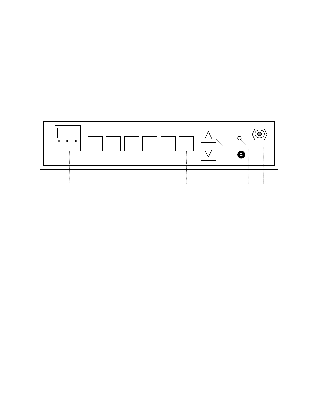
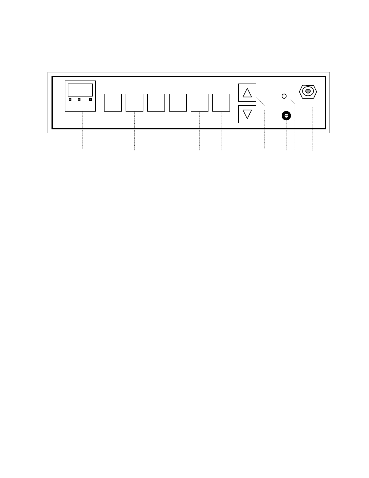
The control panel for all models has a series of command keys which
enables the user to enter set point values for temperature, carbon dioxide, door
heat and to calibrate the unit as required. LED readouts provide the user with
current status information regarding the foregoing parameters.
CONTROL PANEL:
ºC %CO2 HEAT HOLD HI LIMIT SAMPLE
1 23456789101112
FEATURES
SET CAL CO2 TEMP DOOR SCAN
1. LED READOUT: The LED displays current CO2 tension and temperature
in the Incubator and, in the set mode, displays the set point values
for these two parameters as well as door heat setting. It also enables the
user to enter values necessary to calibrate temperature and CO2.
Indicating lights and legends serve to identify which parameter is being
displayed.
2. SET COMMAND KEY: The SET key is the beginning point for and
initiates subsequent actions of the other keys on the control panel.
3. CAL COMMAND KEY: The CAL key permits calibration of temperature
and CO
used to change the readout to correspond with the readings obtained from
known standards of temperature or CO2 measurement. Both temperature
and CO
2 when in this command mode. The Up and Down arrow keys are
2 calibration use the zero point shift method.
FEATURES: (Con’t)
13
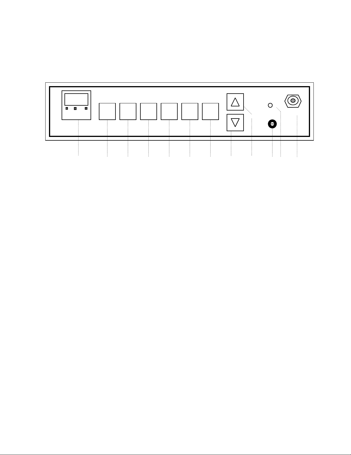
CONTROL PANEL: (Con’t)
SET CAL CO2 TEMP DOOR SCAN
ºC %CO2 HEAT HOLD HI LIMIT SAMPLE
1 23456789101112
4. CO2 COMMAND KEY: Pressing the SET key and then the CO2 key
allows the user with the Up and Down keys to enter the desired carbon
dioxide level in the Incubator.
• High and low limit alarm set points are factory set at ±1% above and
below the user-established set point. In the event CO2 exceeds the
indicated limits, an audible alarm will sound and indicating light
above the key will flash.
• Pressing any key will silence the alarm for a period of one hour. The
user should immediately investigate the reason for the alarm and
take steps to correct the problem. Note that the indicating light
continues to flash. If a problem is not solved the alarm resumes.
• By pressing the CAL (#3) and CO
calibrate CO2. The Up and Down arrow keys will change the readout
to correspond with the readings obtained from known standards of
CO2 measurement.
FEATURES: (Con’t)
2 (#4) keys sequentially users can
14

CONTROL PANEL: (Con’t)
SET CAL CO2 TEMP DOOR SCAN
ºC %CO2 HEAT HOLD HI LIMIT SAMPLE
1 23456789101112
5. TEMP COMMAND KEY: Pressing the SET key and then the TEMP
command key allows the user with the Up and Down arrow keys to
establish the desired set point temperature in the Incubator.
• High and low limit alarm set points are factory-set at ±1ºC. If the
temperature deviates from these limits, an audible, continuous alarm
will sound and the temperature lamp will flash.
• While pressing any key will silence the alarm for a one-hour period,
the user should immediately investigate the reason for the alarm and
take steps to correct the problem. Note that indicating light continues
to flash. If problem is no t corrected, the alarm will resume after one
hour has passed.
• By pressing the CAL (#3) and TEMP (#5) keys sequentially users
can calibrate temperature. The Up and Down arrow keys will change
the readout to correspond with the readings obtained from known
standards of temperature measurement.
NOTE: DECREASES IN TEMPERATURE AND CO2 DUE TO NORMAL DOOR OPENINGS ARE
TOLERATED WITHOUT INITIATI NG THE ALARMS.
FEATURES: (Con’t)
15
CONTROL PANEL: (Con’t)
SET CAL CO2 TEMP DOOR SCAN
ºC %CO2 HEAT HOLD HI LIMIT SAMPLE
1 23456789101112
6. DOOR HEAT COMMAND KEY:
• When the SET key is pressed followed by the DOOR-HEAT key, the
level of heat can be entered with the Up and Down keys as a
percentage value being applied to the inner glass door.
• A flashing DOOR-HEAT indicator light above the key indicates that
heat is being applied to the inner glass door.
• A good starting point for the door heat control is 35%; if fogging still
occurs, increase in 10% increments until fogging disappears.
7. SCAN/HOLD COMMAND KEY: Permits holding the value of a single
parameter for continued viewing or scans alternately between the values
of the two parameters on a 2-second interval.
8. DOWN-ARROW KEY: This key decreases numerical value of the
parameter which has been accessed.
9. UP-ARROW KEY: This key increases the numerical value of the
parameter that has been accessed.
NOTE: A 5 SECOND DELAY AFTER ANY FINAL ENTRY RESULTS IN AUTOMATIC ENTRY
OF THAT CHANGE.
FEATURES: (Con’t)
16

CONTROL PANEL: (Con’t)
SET CAL CO2 TEMP DOOR SCAN
ºC %CO2 HEAT HOLD HI LIMIT SAMPLE
1 23456789101112
10. HI-LIMIT THERMOSTAT: This is a backup temperature controller
that takes charge in the event the microprocessor fails. The hi-limit
thermostat will then control the temperature at slightly above the set point.
11. HI-LIMIT STATUS LAMP: Indicates when the hi-limit is active.
12. SAMPLE PORT: This access port is available for sampling the
atmosphere in the chamber when executing calibration procedure such as
might be done using a Fyrite or similar chemical-based CO2 analysis
procedure.
13. LED RH DISPLAY; MODELS 460RH, 4 65RH, 490RH, 495RH ONLY: With
the toggle switch in the up position, actual chamber humidity is displayed as
% RH. Placing the toggle switch located on the incubator’s back panel, in
the down position, the RH alarm set point is displayed, and the audible
portion of the alarm is disabled.
FEATURES: (Con’t)
WATER-JACKETED MODELS:
13
17

LED READOUT DISPLAY:
LOW WATER INDICATING LIGHT: Low water conditions can be detrimental to
chamber integrity, as well as temperature control. To warn of this condition, a
solid green light will appear just below the LED display area to remind the user to
take corrective action, i.e. add water.
AIR-JACKETED MODELS:
LED READOUT DISPLAY:
ºC LOW WATER %CO2
ºC DECOMTAM %CO2
TIME ELAPSED
DECONTAM™ TIME ELAPSED INDICATING LIGHT: When a DECONTAM cycle
is initiated in radiant warm wall models, the indicating light below the readout will
be lit and the time elapsed (hours, minutes) will be displayed.
FEATURES: (Con’t)
RELATIVE HUMIDITY DISPLAY; MODELS 460RH, 465RH, 490RH, 495RH ONLY:
18

LED READOUT DISPLAY:
RH Calibrate RH Alarm Set point
When the toggle switch located on the incubator’s back panel, is placed in
the up position (normal operation), this LED will display actual chamber RH.
Placing the same toggle switch in the down position will display the RH alarm set
point and will also disable the unit’s audible alarm. The LED readout will flash in
the event chamber RH goes below RH set point.
Below the RH LED readout are two, unmarked, potentiometers. The one
on the left is used for calibrating the RH display to correspond with actual
chamber RH, the one on the right is used to set the RH alarm set point.
The RH alarm set point is factory preset at 80% RH and is user adjustable
from 0 to 100% RH. Using insulated Trimmer Pot Tool, Lab-Line #935-021-00,
or equivalent, insert tool into right opening in the control panel. Clockwise turns
increase alarm set point while counterclockwise turns decrease setting.
Note: toggle switch must be in the DOWN position to monitor RH alarm set point.
When calibrating the LED display for actual chamber RH, place an
independent humidity probe in the approximate geometric center of the chamber.
Using a calibrated, digital RH meter, take reading after chamber RH has
stabilized. Adjust left trim pot with Trim mer Pot Tool, if necessary, by rotating
potentiometer slowly either clockwise to increase or counterclockwise to
decrease.
FEATURES: (Con’t)
CONTROL PANEL: (Con’t)
19

SET CAL CO2 TEMP DOOR SCAN
ºC %CO2 HEAT HOLD HI LIMIT SAMPLE
1234(5)(6)
PROPER SEQUENCING IS IMPORTANT IN OPERATING COMMAND KEYS:
To enter commands correctly, it is important to press the keys in
SEQUENCE. Do not hold down one key and press another key—the action will
not be accepted by the system. The following is the proper sequence in which to
press the keys for the indicated actions:
SET(#1), TEMP(#4): View existing value, retain or change set point using Up
and Down keys.
SET(#1), CO2 (#3): View existing value, retain or change set point using Up
and Down keys.
SET(#1), View existing value, retain or change set point using Up
DOOR HEAT(#5): and Down keys.
CAL(#2), TEMP(#4): Calibrate temperature using Up and Down keys.
CAL(#2), CO2 (#3): Calibrate carbon dioxide using Up and Down keys.
CO2 (#3), CAL(#2),
SET(#1): Install password using Up and Down keys.
TEMP(#4), CAL(#2),
SET(#1): Disable password using UP and DOWN keys.
SCAN/HOLD(#6): Each individual contact of key advances to one of 3 options:
A) continuous viewing of temperature; B) continuous
viewing of carbon dioxide; C) an alternating viewing of the
two.
FEATURES: (Con’t)
ALARMS:
POWER OUTAGE: In the event of a power outage, the LED displa y will flash to
alert the user to take corrective action. If the power outage is of a temporary
nature, pressing any key will restore unit to operating status. Everything operates
normally after a power outage.
20

DOOR AJAR WARNING: In case the door is inadvertently left open beyond a 5
minute period, an audible beep is sounded and is synchronized with the flashing
of the DOOR-HEAT indicator light to warn the user to correct the condition.
AUDIBLE AND VISUAL ALARMS: The following table summarizes the audible
and visual alarms that are initiated upon the occurrence of various events.
AUDIBLE FLASHING FLASHING
BEEP LIGHT LED
ABOVE KEY DISPLAY
Temp (exceeds limits): YES YES NO
CO2 (exceeds limits): YES YES NO
Door Ajar: YES YES NO
Power Out: NO NO YES
Low Water, 460/465 SERIES: NO STEADY NO
Press any key to silence alarm that will remain silent for a period of one
hour. However, the flashing light will continue. If the condition initiating the alarm
remains uncorrected at the end of that time, the audible alarm will resume.
PASSWORD:
In the event that you want to prevent unauthorized access to the operation
of the unit, a password feature is available.
FEATURES: (Con’t)
OPTIONAL ALARM RELAY OUTPUT: REAR OF UNIT
The incubator incorporates an output on the rear panel for use as a central alarm
voltage-free (“dry contacts”) connection port. This output may be tied in with any central
alarm system to give notice of any alarm condition: High or Low Temperature, High or
Low CO2, Low Water Level (water jacket models), Power Outage or Door Opened.
A standard relay is used and is normally energized while the incubator is in
operation. Common, Normally Open, and Normally Closed pin outputs are routed to the
21

rear panel for user access. Enclosed with the incubator is a mating connector that can
be customer wired and used for interfacing with a Central Alarm.
NOTE: The connector is polarized. The rear panel outputs are as shown here:
COMMON
Terminal
“OPENS” on Fault (Normally Closed
WHILE IN OPERATION)
31
4 2
“CLOSES” on Fault (Normally Open
WHILE IN OPERATION)
RELAY OUTPUTS LOCATED ON REAR PANEL
The following ratings are for connection purposes: MAX 5A @ 34VDC or 34VAC
√√√√SHIPPING CARTON:
This should be inspected upon delivery. When received, carefully
examine for any shipping damage before unpacking. If damage is discovered,
the delivering carrier should both specify and sign for the damage on your copy
of the delivery receipt.
SECTION 5
INSTALLATION
22

Open the carton carefully making certain that all parts are accounted for
before packaging materials are discarded. After unpacking, if damage is found,
promptly report it to the carrier and request a damage inspection promptly.
IMPORTANT: Failure to request an inspection of damage within a few
days after receipt of sh ipment absolves the carrier from any liability for damage.
You must call for a damage inspection promptly.
LOCATION:
Place the unit where it will be used, away from external vibration sources,
drafts and wide variations in ambient temperature. Choose a location near a
power supply that matches the unit nameplate requirements.
CAUTION: THIS UNIT IS DESIGNED FOR USE WITH GASEOUS AIR, CO2 OR
NITROGEN ONLY. DO NOT USE WITH ANY OTHER GASES. FAILURE TO
OBSERVE THESE PRECAUTIONS CAN RESULT IN EXPLOSION AND/OR
FIRE AND SERIOUS INJURY AND/OR DEATH AND PROPERTY DAMAGE.
LEVELING:
Level the unit by using a bubble-type level placed on a shelf. Turn the
leveling feet clockwise to raise and counterclockwise to lower the height of the
respective legs of the Incubator. The unit should be level from front to back and
side to side.
ELECTRICAL REQUIREMENTS:
120 VAC models require a 120 VAC, 50/60 Hz power source. They are
supplied with a 3-wire line cord that should be plugged into an outlet designed for
3-prong plugs. If an extension cord is used, it also should be the 3-wire grounded
type. For an outlet designed to accept 2-prong plugs, ungrounded, it is
required that a qualified electrician replace the outlet with a new grounded type.
240 VAC models require a 240 VAC, 50/60 Hz power source. Because of
the variety of plug configurations in use worldwide for 240 VAC power, the unit is
furnished with the plug removed. The user must install a plug to conform with
local code and configuration requirements.
100 VAC models require a 100 VAC, 50/60 Hz power source. Because of
the variety of plug configurations in use worldwide for 100 VAC power, the unit is
furnished with the plug removed. The user must install a plug to conform with
local code and configuration requirements.
If a plug must be installed, use only the 3-prong grounded type, rated for
the unit load requirements and matching the power outlet. Make sure the green
ground wire is secured to the plug ground terminal.
NOTE: LEAVE UNIT DISCONNECTED WHEN NOT IN USE.
INSTALLATION: (Con’t)
SHELVING/PLENUM INSTALLATION-SELF-SUPPORTING SYSTEM COMPONENTS,
TOP PLENUM SHELF SUPPORT SIDE PANELS
23

REAR COVER PANEL
SHELVING/PLENUM INSTALLATION-SELF-SUPPORTING SYSTEM ASSEMBLED
TOP PLENUM
SHELF SUPPORT SHELF SUPPORT
SIDE PANEL SIDE PANEL
REAR COVER PANEL
INSTALLATION: (Con’t)
SHELVING AND PLENUM INSTALLATION-4 STEPS:
NOTE: NO TOOLS OR FASTENERS ARE REQUIRED. THE COMPONENTS FIT TOGETHER
BY HANGING FROM STANDOFFS.
TOP PLENUM, HEAD-ON VIEW:
24

KEYWAY STUDS
(ONTO WHICH THE CHAMBER’S REAR
COVER PANEL KEYHOLE SLOTS WILL FIT)
TOP PLENUM, DOWN VIEW:
KEYHOLE SLOTS
(ONE IN EACH CORNER)
SPACERS STUDS
(
ASSURE THAT CIRCULATION FAN BLADES
DO NOT STRIKE THE PLENUM)
1. Open the outer and inner front chamber doors. Hold the top plenum
with the spacer studs up and the keyway studs toward the rear. Tilt
the panel at an angle and carefully move it into the chamber while
lifting and centering it at the top of the chamber. Insert the larger
keyhole slots located at the plenum’s corners over the four studs
suspended from the chamber ceiling. Slide the top plenum toward
the rear of the chamber locking the plenum into place on the studs.
REAR
FAN VENTS
FRONT
INSTALLATION: (Con’t)
SHELVING AND PLENUM INSTALLATION: (Con’t)
SHELF SUPPORT SIDE PANELS (2), HEAD ON VIEW:
25

2. With the top plenum properly secured to the chamber ceiling, a
space on each side of the plenum is created into which the top of
each of the shelf support side panels will fit. Tilt a support side panel
at an angle and move it into the chamber. Carefully slide the panel
over the studs protruding from one side of the chamber wall and lock
it into place. Repeat this procedure on the other side to install the
second side panel.
REAR COVER PANEL, HEAD-ON VIEW:
TOP PLENUM
REAR PANEL
KEYHOLE SLOTS
(FIT OVER AND ONTO TOP PLENUM
KEYWAY STUDS)
KEYWAY STUDS
3. Move the rear cover panel into the chamber and place its keyhole slots over
and onto the top plenum keyway studs, moving the back wall slots down
and locking them onto the keyway studs.
INSTALLATION: (Con’t)
PORT STOPPER:
REAR COVER PANEL
PORT STOPPER INSTALLED
Insert the inner, narrower edge of the port stopper into the port opening located on
the rear chamber wall. Make sure the outer, wider edge is flush with the rear
interior chamber wall.
INSIDE REAR CHAMBER WALL, SIDE VIEW
26

OUTSIDE CHAMBER REAR INSIDE CHAMBER FRONT
TOP PLENUM, UP VIEW:
BASE
HEAD
LOCKING
GROMMET
STOPPER PUSHED FLUSH AGAINST INSIDE
REAR OF CHAMBER WALL, SIDE VIEW
FRONT
FOUR
KEYLOCK HOLES
REAR
4. Press a locking grommet, two supplied, into the two front keyhole slots
adjacent to the stud from which the top plenum is secured. Make sure that
the entire head of the locking grommet is inserted into the keyhole slot.
This prevents the top plenum from being accidentally pulled out.
27

INSTALLATION: (Con’t)
INSTALLATION OF GAS FILTER INTERFACE ASSEMBLY KIT #018-514-00:
KIT #018-514-00 INCLUDES:
• 4, Hose Clamps (#250-331-00)
• 1, In-Line Filter (#525-034-00)
• 1, 10 ft. (4.57m) length of 1/4” (6.35mm) ID PVC tubing (#720-418-00)
INSTALLATION PROCEDURE:
See next page for illustration.
• Turn the unit power switch to the OFF position.
• Connect tubing to CO2 tank gas outlet.
• Connect 1/4” (6.35 mm) ID tubing to hose barb on one side of in-line filter
and secure with hose clamp; connect tubing to in-line filter hose barb on its
other side and secure with hose clamp.
• Connect tubing with in-line filter in place to the appropriate gas inlet fitting
on the back of the unit.
• Set the supply regulators at 10 psi.
• Check all of the connections for leaks.
• Turn the unit power switch to the ON position.
WARNING: HIGH CONCENTRATIONS OF CARBON DIOXIDE PRODUCE
METABOLIC ABNORMALITIES, DISTURBANCES OF THE CENTRAL
NERVOUS SYSTEM AND CARDIAC INSTABILITY. UNCONSCIOUSNESS
MAY OCCUR AT CONCENTRATIONS ABOVE 10%.
28

INSTALLATION: (Con’t)
INSTALLATION OF GAS FILTER INTERFACE ASSEMBLY KIT #018-514-00: (Con’t)
BACK OF UNIT
REAR PANEL VIEW, EXTERIOR:
IN-LINE FILTER BACK OF UNIT
#525-034-00
HOSE CLAMP HOSE CLAMP
#250-331-00 #250-331-00
1/4” ID TUBING
#720-418-00
HOSE CLAMP 1/4” HOSE BARB
#250-331-00 CONNECTIONS
SET PRESSURE AT 10 PSI.
PRESSURE REGULATORS AND GAUGES MUST
BE INSTALLED ON EACH T ANK. CHECK LOCAL
GAS SUPPLIER FOR PROPER REGULATORS.
100% CO2
(CO2 FITTING)
29

INSTALLATION: (Con’t)
STANDARD AND SIPHON TYPE CO2 GAS CYLINDERS
STANDARD TYPE (CORRECT) SIPHON TYPE (INCORRECT)
2
11 3 5
246
38
7
1. Compressed Gas Association 1. Warning tag indicating that
#320 connector. cylinder is siphoning type.
2. Gas headspace. 2.* Aluminum ring.
3. Liquid CO2 filled to 68% 3.* Gold band.
equal weight of water that 4.* Stamp or marking on cylinder:
cylinder would hold at 60ºF. "Siphon" or "Eductor Tube".
5.* Valve should be of special type for
service.
6.* Withdrawal tube draws up the liquid
2.
CO
7.* Gas head space.
8.* Liquid CO2 filled to 68% equal weight of
water that cylinder will hold at 60ºF.
*NOTE: SOME GAS SUPPLIERS WILL HAVE NO MARKINGS TO INDICATE AN "EDUCTOR
TUBE" OR "SIPHON" TYPE CYLINDER. BE SURE TO ORDER DRY, LAB-GRADE CO2.
Be sure to obtain a dual-stage regulator from the gas supplier for the CO2
tank that is to be installed according to local codes.
30

INSTALLATION: (Con’t)
460 SERIES, WATER-JACKETED MODELS, FILLING WITH WATER:
Capacity of the water jacket is 10.7 gallons/40.5 liters of water. Fill the
jacket only with distilled water. For optimum Incubator life, use a distilled water
with an electrical resistivity of 500,000 ohms to 1 MEG ohm maximum, as
measured between opposite faces of a centimeter cube of an aqueous solution
per ASTM D 1125-82.
WE DO NOT RECOMMEND USING 18 MEG OHM DEIONIZED WATER. If
this is the only source of treated water available, mix with regular tap water to
dilute to 1 MEG ohm maximum.
As a protection against the growth of fungi, a quality fungicide can be added
according to the use ratio, parts compound versus capacity of water jacket, of the
selected compound. Follow manufacturer’s instructions completely.
CAUTION: TO PREVENT DAMAGE TO THE WATER CHAMBER, DO NOT
ADD WATE R AT A HIGH FLOW RATE OR AT HIGH PRESSURE.
CAUTION: AIR VENT FOR WATER-JACKET IS SMALL PIPE ON THE LEFT
HAND SIDE OF THE BACK OF THE UNIT AND MUST BE KEPT FREE OF ALL
OBSTRUCTIONS TO ALLOW AIR TO ESCAPE. THE INCUBATOR CHAMBER
CAN BE DAMAGED FROM PRESSURE BUILD-UP FROM EXPA NS ION AND
CONTRACTION DURING HEATING AND COOLING CYCLES.
31

INSTALLATION: (Con’t)
INITIAL FILLING OF WATER JACKET, 460 SERIES:
1. Turn unit on. The low-water LED will display a low-water message.
2. To fill the water jacket, open the unit’s front door and locate water inlet, top left
under front control panel.
FRONT/LEFT OF UNIT:
LED READOUT DISPLAY
WATER INLET (FEMALE)
QUICK-CONNECT RESET BUTTON QUICK-CONNECT
WATER FITTING (MAL E)
SIDE VIEW
FLEXIBLE HOSE
3. Verify overflow outlet on rear of unit is not obstructed. Connect a ¼” (6.35 mm) ID
piece of tubing to overflow outlet and place other end of tubing in a 1 liter container
to catch any possible overflow.
4. Attach appropriately sized tubing from distilled water source to the water inlet.
5. Turn distilled water source on. Flow rate should not be greater than 1 liter/minute.
6. Monitor low-water light on control panel until it goes out and
immediately stop filling procedure—turn off the distilled water source WITHIN THE
NEXT FEW SECONDS, all excess water will run from the overflow outlet located
at the rear of the unit.
32

INSTALLATION: (Con’t)
460 SERIES:
NOTE: PUSH THE QUICK-CONNECT ON THE WATER INLET UNTIL IT CLICKS
BEFORE INSERTING TUBING TO INSURE A SECURE CONNECTION. THE
SMALL QUICK-CONNECT RESET BUTTON ON THE LEFT SIDE OF THE
WATER INLET CAN BE PUSHED IF THE WATER INLET WAS
INADVERTENTLY SET.
QUICK-CONNECT RESET BUTTON QUICK-CONNECT
CAUTION: TO PREVENT DAMAGE TO THE WATER CHAMBER, DO NOT
ADD WATE R AT A HIGH FLOW RATE OR AT A HIGH PRESSURE.
WATE R OVERFLOW OUTLET:
• Connect appropriate-sized tubing from the water flow outlet (circled) to a
sink, floor drain or in an adequately sized receptacle (bucket, large pan).
BE ADVISED: IT IS RECOMMENDED THAT WHEN FILLING THE UNIT IT
SHOULD NOT BE LEFT UNATTENDED. A SURPRISING LARGE AMOUNT
OF WATER CAN RUN FROM THE WATER OVERFLOW OUTLET WITHIN A
FEW SE CONDS AFTER FILLING.
UNIT REAR PANEL: WATER OVERFLOW OUTLET (CIRCLED)
33

INSTALLATION: (Con’t)
DRAINING OF WATER JACKET, 460 SERIES:
With the use of distilled water, periodic draining and refilling of the
water jacket is not necessary. In the event the incubator is moved however,
the water jacket should be drained. The drain is located at the left front
bottom of the cabinet and is opened when the 1/4” adapter fitting (supplied
with the unit) is inserted.
• Disconnect unit from electrical power.
• Connect the barbed end of the adapter fitting to appropriate-sized
tubing. Place the other end of the tubing in a sink, floor drain or in an
adequately sized receptacle (bucket or large pan). Connect the
other end of the fitting to the incubator.
• Leaving drain tube connected, flush with distilled water to remove
any possible deposits within the water jacket.
• Disconnect the adapter fitting and add 500 ml of quality rust
preventative such as ethylene glycol.
Fill water jacket per instructions on page 32 .
HUMIDIFICATION (if required):
As a preventive measure against mineral deposit build-up, USE ONLY
DISTILLED WATER. Mineral deposits can affect the CO2 control. Check water
level at intervals to maintain conditions of humidity required for work being done.
To humidify the chamber atmosphere, use the stainless steel pan which is
included, pouring distilled water into it. DO NOT flood the bottom of the chamber
with water.
While the addition of a fungicide to the water will assist in controlling
contamination, it may also affect the results of experiments conducted with cells,
viruses and other materials. These factors should be taken into account when
deciding to use or not to use a fungicide.
34

DANGER: DO NOT USE IN THE PRESENCE OF FLAMMABLE OR
COMBUSTIBLE MATERIALS OR EXPLOSIVE GASES. DO NOT USE IN THE
PRESENCE OF PRESSURIZED OR SEALED CONTAINERS—FIRE OR
EXPLOSION MAY RESULT, CAUSING DEATH OR SEVERE INJURY.
WARNING: DO NOT HEAT ANY SUBSTANCE ABOVE A TEMPERATURE
WHICH WILL CAUSE IT TO EMIT TOXIC FUMES—DEATH OR SEVERE
INJURY MAY RESULT.
DANGER: USE ONLY AN INERT GAS SUCH AS CARBON DIOXIDE IN THE
INCUBATOR. DO NOT UNDER ANY CIRCUMSTANCE INJECT OXYGEN OR
OTHER EXPLOSIVE GAS OR MIXTURE INTO UNIT. FAILURE TO OBSERVE
THESE PRECAUTIONS CAN RESULT IN EXPLOSION AND/OR FIRE AND
SERIOUS INJURY OR DEATH TO PERSONNEL AND PROPERTY DAMAGE
START-UP:
• Connect unit to power supply meeting the requirements as noted on the
• Turn on the Incubator with rocker switch that is located on back left side.
SECTION 6
OPERATION
nameplate.
• All display segments and parameter lamps should light for 5 seconds.
OPERATING BASICS:
• Press the SET key first and then the parameter—CO2, TEMP, DOOR
HEAT—which is to be adjusted.
• Use the UP and DOWN arrow keys to enter the desired value.
• Wait 5 seconds and the value is entered automatically into the unit's
nonvolatile memory. Storage is confirmed via 2 short beeps at the end of 5
seconds.
• If you access a parameter and initiate no action within the time frame of 10
seconds, the unit times out and returns to the prior state.
• Each press of the SCAN/HOLD key is programmed to follow a sequential
pattern as follows: HOLD temperature (for continuous viewing), HOLD CO2
(for continuous viewing) and alternate scanning of temperature and CO2.
• To view your previously established set point for any parameter, press SET
and the TEMP, CO2 or DOOR HEAT key(s)—unit will revert to its normal
display after 10 seconds.
35

OPERATION: (Con’t)
PASSWORD FEATURE:
1. To prevent unauthorized entry to values which have been set, a password
feature is available with your unit.
2. SET, CAL, CO2 and TEMP keys have the numbers 1, 2, 3 and 4 below that
are used to enter or disable a password. Select a 3-digit password from
001 through 999 FYI: 000 is not a valid password). After power up and
after pressing any key, press 3, 2 and 1 in sequence (i.e. CO2, CAL and
SET); enter your numerical password by using the UP or DOWN arrow key.
3. Once your password is entered, wait 5 seconds and the unit will store this
value in its nonvolatile memory. REMEMBER TO NOTE THE PASSWORD
IN A PLACE FOR SAFEKEEPING AND ACCESSIBLE TO YOURSELF OR
A COLLEAGUE.
4. Subsequent access is denied unless the correct password is entered. Any
keystroke will display 00 and YOU HAVE 5 SECONDS within which to enter
the correct password using the UP or DOWN arrow key.
5. To disable the password: enter the password, wait for - - - to appear on
the readout, enter 4, 2, 1 (i.e. TEMP, CAL and SET) and the password is
disabled.
SETTING OPERATING TEMPERATURE AND HI-LIMIT SETPOINT:
• Press the SET and TEMP keys sequentially and using the UP and DOWN
arrow keys, select the set point temperature.
• Rotate the HI LIMIT thermostat fully clockwise.
• Set CO2 set point to zero—accuracy will not be achieved until the
temperature has stabilized.
❑ Press the SET and CO2 keys sequentially and using the UP
and DOWN arrow keys, adjust LED readout until a value of
00.0 is obtained.
❑ Wait 5 seconds to finalize the selection.
• Allow sufficient time for the unit to reach and stabilize at the set point
temperature plus an additional hour or two for unit to cycle at the
temperature—4 HOURS FOR 37ºC IS TYPICAL.
36

OPERATION: (Con’t)
SETTING OPERATING TEMPERATURE AND HI-LIMIT SETPOINT: (Con’t)
• After this time has elapsed, rotate the HI-LIMIT thermostat
counterclockwise while watching the red lamp. When the lamp is lit, you
have adjusted the HI-LIMIT set point to be equal to the operating set point.
NOTE: DO NOT LEAVE HI-LIMIT AT THIS SETTING
• Now rotate the HI-LIMIT thermostat clockwise 30 degrees of rotation past
the point where the lamp goes out. THIS DISTANCE SHOULD BE
SIMILAR TO THE DISTANCE FROM THE TWELVE O’CLOCK TO THE
ONE O’CLOCK POSITIONS. This establishes a buffer of a few degrees
between the operating set point and the HI-LIMIT temperature set point and
allows PID control to function normally.
NOTE: UNDER NORMAL OPERATING CONDITIONS, THE HI-LIMIT LED SHOULD
NEVER COME ON. IF IT DOES, READJUST SLIGHTLY CLOCKWISE.
CONDENSATION ON INNER GLASS DOOR:
• After the unit has been operating, you can determine what, if any,
condensation is forming on the inner glass door. To dissipate
condensation, press the SET and DOOR HEAT keys to access this
function.
• Using the UP and DOWN arrow keys, select a value as a percentage of the
heater output. Heat will be applied by setting the door heat percentage.
Each % translates into 0.5 Watts of door heat. For example, 10 will
produce 10% of the available heating capacity. As experience is gained
through trial and error, you will be able to select more precisely the heating
value required to remove any condensation. As a general starting point,
30% at 37ºC may be selected.
• Correct setting of the door heat control depends on varying factors such as
chamber temperature and whether or not you choose to add water
(humidity) into the chamber. In general, the setting should be to produce
the minimal amount of heat necessary to eliminate glass door condensation
and no more. If unsure of the amount of heat to produce, start at a low
value and increment the setting by 5% every couple of hours until
condensation is eliminated. Once set, the door heat percentage need not
be changed again, unless you change the temperature set point and/or your
humidity requirements. The setting you choose is, of course, stored in nonvolatile RAM memory in case of power outages.
37

OPERATION: (Con’t)
DECONTAM™ PROCEDURE: AIR JACKETE D MODE LS WITH THERMAL
CONDUCTIVITY SENSOR ONLY:
The decontam cycle is initiated by sequentially pressing SET, TEMP and
holding the UP arrow key until the temperature reaches 100ºC. The unit will hold
this temperature for a period of 12 hours and the time elapsed during the cycle is
displayed on the LED readout; the only way that the cycle can be aborted is by
turning off the power switch.
DECONTAM™ WARNING:
DO NOT, UNDER ANY CIRCUMSTANCES, USE DECONTAM IN THE CHAMBER
WITH HUMIDIFICATION WATER PRESENT INSIDE THE CHAMBER.
ALWAYS REMOVE ALL WATER BEFORE
BEGINNING DECONTAM.
TEMPERATURE CALIBRATION:
The Incubator is calibrated at the factory. However, if required, the
temperature readout may be calibrated by pressing the following keys
in sequence: CAL, TEMP.
It is important to remember that opening or keeping the outer door open
shuts off the chamber’s air circulating fan. The door must be closed to operate
the fan.
• Using a calibrated digital thermometer and a thermocouple, place the
thermocouple in the approximate geometric center of the chamber.
• Allow sufficient time for the chamber temperature to stabilize.
• Use the UP and DOWN arrow keys to correct the displayed temperature on
the LED readout to match your chamber temperature reading. Wait 5
seconds and the adjustment is self-entering.
• Be sure to shut the outer door in order to operate the fan to assure the
circulation of air inside the chamber.
CO2 CALIBRATION:
In like manner, the CO2 reading can be calibrated against a known
standard such as the Fyrite method of analyzing CO2. To access the correct
command mode, press the CAL, CO2 keys sequentially.
Using a Fyrite or similar device, obtain the actual CO2 tension in the
chamber via the front panel CO2 sample port.
If there is a difference between the Fyrite reading and LED display of
CO2, press CAL and CO2 in sequence and use the UP and DOWN arrow keys
to adjust the displayed CO2 value to match the value obtained with the Fyrite or
device of comparable accuracy and reliability.
All internal CO2 parameters automatically track this change.
38

OPERATION: (Con’t)
HINTS ON USING THE FYRITE*:
The following information is intended to supplement that found in the
Fyrite manual and is based on experience working with users of our Incubators.
One of the most important aspects of using the Fyrite procedure and one that is
frequently overlooked is the condition of the fluid. The Fyrite accepts a sample of
the Incubator's environment into its own chamber where it is absorbed by the
Fyrite fluid to determine the CO2 percentage or tension. Of special importance is
keeping outside air from the sample drawn from the Incubator. Any outside air
contaminating the sample is detrimental to an accurate reading, and,more
importantly, to the growth of your cells.
Inspection of the fluid should be performed only with the user wearing
protective gloves, as the Fyrite fluid is slightly corrosive. The inspection should
review the following:
• THE DATE OF THE LAST FLUID CHANGE: Old fluid will not absorb as
much CO2 and will produce a false reading. This may lead the user to
recalibrate the Incubator to higher CO2 tensions that can prove lethal to cell
cultures. Fyrite fluid should be changed after approximately 350 uses. This
approximates a change of fluid once a year if the Fyrite procedure is carried
out on a daily basis. Keep track of the number of uses and if the Fyrite is
used with more than one Incubator. Experience shows that the color of the
fluid is not as important as the age of fluid.
• CHECK THE CONTAINMENT VESSEL AND HOSES AT LEAST ONCE A
MONTH: Make sure that there are no cracks in the vessel or leakage of
fluid to the outside of the container. This can indicate a leaky seal or
internal crack. Hoses should be stretched slightly and inspected for cracks
or holes. This is critical as cracks and/or holes in the hoses can draw in
outside ambient air and produce a false reading.
• CHECK THE FLUID DAILY AND ADJUST THE SLIDE GAUGE TO READ
ZERO: If you have adjusted the slide gauge all the way down and the fluid
level is still too low, place a couple of drops of distilled water into the
plunger on the top of the Fyrite. Depress the plunger and the water will
transfer into the Fyrite causing the fluid level to rise. Repeat this procedure
until the fluid level reads correctly.
CAUTION: A LITTLE WATER GOES A LONG WAY— USE ONLY A COUPLE
OF DROPS OF DISTILLED WATER AT A TI ME .
CAUTION: DO NOT USE FYRITE FLUID TO ADJUST THE LEVEL OF FLUID
USE DISTILLED WATER ONLY. THE ONLY TIME TO USE FRESH FYRITE
FLUID IS WHEN YOU CHA NGE IT DUE TO THE AGE OF THE FLUID.
*Trademark of Bacharach Instruments.
39

OPERATION: (Con’t)
HINTS ON USING THE FYRITE: (Con’t)
Inspect the Fyrite filter in the clear plastic casing between the hoses for
any contamination or growth. Change it if necessary.
CAUTION: MAKE SURE THE FILTER IS MOIST BEFORE YOU TAKE YOUR
READING. A MOIST FILTER IS A MUST FOR AN ACCURATE READING.
To moisten the filter, remove the end of the short hose without the
squeeze bulb that connects to the Incubator. Add several drops of distilled
water to the filter, replace the hose and squeeze the bulb. Release the bulb and
the water will be drawn into the filter. Squeeze the bulb and quickly release it to
remove any excess water. You will see this water (if any) come out of the end of
hose that is closest to the squeeze bulb. This is the cupped end that is
depressed onto the Fyrite.
TAKING A FYRITE READING:
It is recommended that Fyrite CO2 and independent temperature
tests be performed at intervals to be determined individually or as dictated
by established protocol. Some laboratories conducting critical work may
want to record CO2 and temperature readings on a daily basis.
CAUTION: THE INCUBATOR MUST BE STABLE.
First, clear the Fyrite of any residue CO2. Simply depress the plunger on
the head or the top of the Fyrite taking care not to cover the hole—this
introduces fresh ambient air into the Fyrite chamber. Release the plunger and
turn the Fyrite upside down, holding it at a 45-degree angle until most of the
bubbles surface and the fluid has filled the head. Even the smallest bubbles
may contain CO2, so that it is important to let most of the smaller bubbles surface.
Now turn it right side up and hold it at 45 degrees. Allow the fluid to fill the
Fyrite and depress the plunger again—this clears the Fyrite of any CO2 that
might cause a false reading.
Next, attach the filter side of the hose to the Incubator's CO2 sample port.
Remove the brass tube, if present, from the Fyrite hose, as it is not needed and
attach the hose to the CO2 sample port. The brass tube was once used with
older Incubators that utilized a hole in the Incubator wall or door to measure
2 but this method proved to cause contamination problems.
CO
LOOK AT YOUR FYRITE GAUGE AND ADJUST THE ZERO IF
NECESSARY.
Take the squeeze bulb end of the hose and with the hole of the cupped
end facing down, place it onto the plunger of the Fyrite and hold it firmly in
position.
IMPORTANT: ONCE YOU HAVE DEPRESSED THE PLUNGER OF THE
FYRITE, IT IS CRITICAL THAT IT NOT BE RELEASED DURING THE
FOLLOWING PROCEDURE.
40

OPERATION: (Con’t)
TAKING A FYRITE READING: (Con’t)
Depress the plunger and hold it down. It is very important not to allow the
plunger to spring up—if this occurs. you will be repeating an already existing
reading. It will not matter how many times you pump the squeeze bulb, as long
as you hold the plunger down you will introduce only one sample to the Fyrite.
But, by releasing the plunger and immediately pushing it back down, you will
then be adding an additional sample to the Fyrite chamber causing the reading
to double or triple. In the event that it is difficult to hold the plunger down while
pumping the squeeze bulb, find a more suitable or comfortable position.
Without releasing the plunger, pump the squeeze bulb at least 20 to 30
times—this assures complete and thorough transfer of the sample to the Fyrite
chamber. Once the bulb has been pumped the required number of times, HOLD
THE SQUEEZE BULB IN THE SQUEEZED-POSITION and release the
pressure on the cup which will also release the plunger. This traps the sample
from the Incubator in the Fyrite chamber and allows the fluid to absorb the CO2.
With the plunger now released, turn the Fyrite upside down again and
hold at a 45-degree angle to allow the smaller bubbles to surface while the fluid
fills the chamber head. Reverse and turn Fyrite right side up and hold at a 45degree angle to allow the same thing to happen. Repeat this procedure—hold
upside down at 45-degree angle and right-side up at 45-degree angle. Finish by
shaking the Fyrite slightly while holding at 45-degree angle to allow residue
droplets of fluid to drain into the measuring tube.
Read the gauge: It should match or be close to your CO2 set point. It is
possible that you may be off as much as ±3%. If you read more than 8%, it is
possible that you may have introduced two samples or the Incubator is way out
of calibration. If a wide variation between the reading and CO2 set point exists, it
is recommended that the sampling and measurement procedure be repeated.
Once the possibility of any error in Fyrite reading has been eliminated,
calibrate your Incubator to conform with the reading obtained. It only takes
about 5 minutes and will improve incubation protocols and can forewarn of
possible Incubator problems before they become serious.
RS232 STATISTICS FOR ALL MODEL INCUBATORS:
DESCRIPTION:
An output from the Incubator is available at all times via the rear panel for
RS232 connection to a printer or computer at a FIXED 1200-BAUD RATE. The
output consists of TEMPERATURE AND CO
OUTAGE confirmation upon power up.
Outputs are present at 1-MINUTE INTERVALS (also fixed). The software will
determine whether or not the receiving device expects to use a CTS (Clear- ToSend) protocol or not and will issue data accordingly. CTS is sometimes referred to
as the "busy" line and is mostly used by slower devices such as Line Printers.
When a Capture program is used to receive data such as in a PC, CTS is generally
not used and THE INCUBATOR SOFTWARE WILL COMPLY AUTOMATICALLY.
2 data as well as a POWER-
41

OPERATION: (Con’t)
RS232 STATISTICS FOR 465/495 SERIES INCUBATORS: (Con’t)
• The output format used is as follows:
PRINTER (CTS USE): DOUBLE LINE :
⇒ Temp = XXX. X C(LF)(CR) <<Line Feed/Carriage Return
⇒ CO2 = XX.X% (LF)(CR)(LF)(CR)
• Capture Program (PC): Single Line:
⇒ Temp = XXX.X C, CO2 = XX.X% (LF)(CR)
• Upon resumption of power after a power outage or any power-up event:
Single Line:
⇒ ...RESUME SYSTEM POWER (LF)(CR)
• The RS232 data pins available at the rear of the unit (D-subminiature 9-pin)
are:
⇒ Signal Ground: Pin 5 (To your device ground)
⇒ Transmit (TX): Pin 3 (To your device "Receive data" input)
⇒ CTS (RX): Pin 8 (From your device CTS, RTS or DTR output)
• Characters are transmitted in an 8-bit UART fashion:
⇒ >> 10 bits are transmitted: a start bit (0), 8 data bits (LSB) and a stop bit.
⇒ NO additional parity bits are included and the MSB data bit is always
zero.
⇒ >> Meets RS232C and V.24 Electrical Specifications.
POWER MAINS PROTECTION: MODELS 460-1CE, 465-1CE, 490-1CE & 495-1CE
If a fuse blows, have a qualified person replace it with a properly rated
fuses—these now follow here: The internal primary of the transformer fuse is:
0.6 AMP, Littlefuse #313.006, Slo-Blo Type (Lab-Line Part #330-370-00);
internal motor lead fuse is: 1 AMP, Littlefuse #313.001 (Lab-Line Part #330369-00).
42

BE ADVISED:
NOTE: MAKE NO ATTEMPT TO SERVICE OR REPAIR A LAB-LINE PRODUCT UNDER
WARRANTY BEFORE CONSULTING YOUR LAB-LINE DEALER. AFTER THE WARRANTY
PERIOD, SUCH CONSULTATION IS STILL ADVISED, ESPECIALLY WHEN THE REPAIR
MAY BE TECHNICALLY SOPHISTICATED OR DIFFICULT.
IF ASSISTANCE IS NEEDED BEYOND WHAT THE DISTRIBUTOR CAN PROVIDE, PLEASE
CALL THE LAB-LINE CUSTOMER RELATIONS DEPARTMENT AT (563) 556-2241 OR
(800) 522-5463. NO MERCHANDISE, HOWEVER, SHOULD BE RETURNED DIRECTLY TO LABLINE WITHOUT PRIOR APPROVAL FROM LAB-LINE.
CAUTION: DISCONNECT PLUG FROM ELECTRICAL OUTLET BEFORE
ATTEMPTING ANY MAINTENANCE OR REPAIR OF THIS UNIT.
CLEANING:
Every 6-months, inspect the chamber. If water is added for humidity,
remove any scale accumulation. Clean the stainless steel interior with any good
scale remover or dilute acetic acid and a synthetic scouring pad. DO NOT USE
chlorine-based cleansers or bleach, scouring pads with metallic content or
harsh abrasives to clean any part of the Incubator.
SECTION 7
MAINTENANCE
DOUBLE-DOOR CONSTRUCTION WITH INNER DOOR DEFOGGER:
DOOR CANNOT BE REPAIRED, ENTIRE ASSEMBLY MUST BE REPLACED.
CARE AND CLEANING OF STAINLESS STEEL:
CAUTION: DISCONNECT UNIT FROM POWER SOURCE PRIOR TO
CLEANING. WE RECOMMEND ALL SERVICE BE PERFORMED BY
QUALIFIED SERVICE PERSONNEL.
WARNING: ELECTROLYSIS CAN DAMAGE STAINLESS STEEL. THIS
OCCURS WHEN AN OBJECT IS ALLOWED TO REST DIRECTLY ON THE
SURFACE OF STAINLESS STEEL, TRAPPING MOISTURE THAT BECOMES
OXYGEN-STARVED, BUT IS SURROUNDED B Y WATER-CONTAINING
OXYGEN.
43

MAINTENANCE: (Con’t)
THE ALLOY CALLED STAINLESS:
Stainless steel is an alloy of steel with chromium and nickel that
increase the metal’s resistance to rust and corrosion. Yet, if not properly cared ,
stainless steel can rust and corrode.
Exposure to air provides the passivation, or oxide layer coating, for clean
stainless by producing a thin, durable chromium-oxide film that forms rapidly
on the alloy surface to give stainless its characteristic “stainless” quality. Also
exposure of the surface to other oxidizing environments can produce a
passivating film or coating.
However, if free oxygen is not available due to scale or contamination
buildup the metal surface may become vulnerable to rusting and corrosion as
well as pitting. But by maintaining neutral pH and conducting frequent cleanings
with detergent and water, years of trouble-free service from stainless steel
products can be obtained.
SOME STAINLESS GUIDELINES TO CONSIDER:
Distilled water is recommended. Please note, if this water is very pure it
may be corrosive to stainless. When filling a bath or incubator, ALWAYS ADD 2
to 40 PPM (20 TO 40 MG/LITER) DISODIUM PHOSPHATE OR SODIUM
BICARBONATE, ADJUSTING DOSAGE TO PROVIDE A pH VALUE OF 7 TO 9.
If not available, use clean, aerated soft tap water provided the total solids
concentration is < 500 PPM.
WE DO NOT RECOMMEND USING 18 MEG OHM DEIONIZED WATER. If
this is the only source of treated water available—mix with regular tap water at a
50/50 ratio.
THE pH FACTOR:
Check pH regularly. If pH is <6.0, add disodium phosphate to increase pH
to a 7 to 9 value. Sodium carbonate or sodium bicarbonate may be used but
they tend to form scale that must be rinsed out regularly. If pH is >10.0, add
sodium bisulfate to decrease pH to a 7 to 9 value. Avoid adding harsh alkalines
or acids since these may cause localized corrosion and result in unstable pH.
SPECIAL STAINLESS CONSIDERATIONS:
WARNING: IF IT IS NECESSARY TO USE THE FOLLOWING CHEMICALS,
LIMIT EXPOSURE TIME TO A MAXIMUM OF 3 HOURS—ALWAYS CLEAN
SURFACES IMMEDIATELY AFTER USE.
Chemicals which should be limited to a 3-hour maximum exposure time to
stainless steel are:
Aluminum chloride E.D.T.A. Potassium permanganate
Barium chloride Ferrous chloride Potassium thiocyanate
Calcium chloride Lysol Sodium hypochlorite
Chlorinated Lime Mercury salts Stannous chloride
Citric acid (boiling) Phenol Tartaric acid
Dakin’s solution
44

MAINTENANCE: (Con’t)
BE ADVISED: NEVER USE THE FOLLOWING ON STAINLESS STEEL:
Aqua regia
Ferric chloride
Iodine
Sodium acid
Sodium azide
Chemical spills, especially those agents listed here, should be removed
as soon as possible and the stainless steel surface cleaned with mild soapy
water followed by a clean water rinse.
CLEANSING AGENTS:
Anti-fungal and anti-bacterial additives are permissible to use as long as
the pH of the aqueous solution is kept within the range of 7 to 9. These are
available through laboratory distributors. But, be sure to CONFIRM that they are
not harmful to stainless steel.
STAINLESS CLEANING METHODS:
Do not use any metallic pads. Instead, for stubborn stains, use a plastic
light-duty cleansing pad and rub GENTLY in the direction of the metal grain.
If stains continue to persist, use one of the following chemicals and methods.
CAUTION: EXTREME CARE MUST BE TAKEN WHEN HANDLING THESE
MATERIALS. ALWAYS WORK IN AN AREA WITH ADEQUATE
VENTILATION. USE THE PRECAUTIONS AS OUTLINED IN THE MATERIAL
SAFETY DATA SHEET (MSDS) AND THE MANUFACTURER’S
INSTRUCTIONS FOR THE PRODUCT BEING UTILIZED. ALSO, FOLLOW THE
PERSONAL PROTECTION INDEX FOUND IN THE HAZARDOUS MATERIALS
INFORMATION SYSTEM (HMIS) SECTION OF THE MSDS.
NOTE: THE USE AND DISPOSAL OF THESE CHEMICALS MAY BE REGULATED BY YOUR
LOCAL CITY CODES; CONSULT THOSE REGULATIONS BEFORE OF DISPOSING OF THESE
MATERIALS.
• Any of a variety of “scale removers” available at local supermarkets or
hardware stores used for the cleaning of coffee marks, humidifiers or
vaporizers.
• A 15% to 35% phosphoric acid solution available from laboratory supply
distributors for scale and rust removal. Allow solution to soak the surface
affected until rust and scale is loosened. Immediately follow with a clean
water rise.
45

MAINTENANCE: (Con’t)
STAINLESS CLEANING METHODS: (Con’t)
• Citric acid based cleaners.
• Bathroom tub and tile cleaners.
• A mixture of 20% nitric acid and 1.5% hydrofluoric acid (or hyrochloric acid).
Swab solution on surface allowing it to remain until rust is loosened.
Immediately follow with a clean water rise. This method should ONLY be
used if SEVERE rust and scale stains are present.
• Oxalic acid 2% to 5% in warm water. Swab solution on surface allowing it
to remain until rust is loosened. Immediately follow with a clean water rise.
This method should ONLY be used if SEVERE rust and scale stains are
present.
Regardless of the approach utilized, ALWAYS follow the manufacturer’s
directions and allow the chemicals to do the cleaning with MINIMAL
scrubbing. Always follow cleanings with a clean water rinse. Air dry.
MATERIALS EFFECTIVE IN DISINFECTING STAINLESS:
• Glutaraldehyde
• Alcohol
BE ADVISED: THIS INFORMATION IS INTENDED AS GUIDELINES ONLY
AND LAB-LINE INSTRUMENTS, INC. MAKES NO CLAIM AS TO THE
SUITABILITY TO ANY PARTICULAR SITUATION. CONSULT YOUR STAFF
CHEMIST TO DETERMINE WHAT WOULD BE BEST FOR YOUR
STAINLESS STEEL PRODUCT AND LABORATORY.
UNIT REPAIRS:
In the event that your unit becomes inoperative, consult with your local
dealer for assistance.
46

120 VAC INCUBATORS (WITH PLUG):
DESCRIPTION PART NUMBER
Axial Fan: 160-136-00
Blower Motor: 370-278-00
Circuit Breaker, 5 Amp: 330-118-00
Circuit Breaker, 10 Amp: 330-119-00
Fuse, 1 Amp: 330-369-00
Cordset: 470-311-00
Foot, Leveling: 790-401-00
Gasket, Outer Door: 530-246-00
Gasket, Glass Door: 530-258-00
Heater, Outer Door: 340-351-01
Printed Circuit Board Assembly:
460: 018-476-00
465: 018-477-00
490: 018-474-00
495: 018-475-00
460RH: 018-476-00
465RH: 018-477-00
490RH: 018-474-00
495RH: 018-475-00
RTD Sensor: 410-632-00
Shelves (5): 593-108-00
Solenoid Valve: 950-135-00
Strain Relief: 380-571-00
Switch, Door: 440-080-00
Switch, Power: 440-359-00
Thermostat, High Limit: 920-301-00
Tube Heater: 340-356-01
Door Strain Relief: 380-081-00
Blower Wheel: 160-184-01
Control Panel Keyboard:
460, 465, 490, 495: 682-285-00
460RH, 465RH, 490RH, 495RH: 682-566-00
CO2 Sensor: 017-924-00
Humidity Sensor: 410-659-00
Wiring Schematic, Model 465: 228-553-19
Wiring Schematic, Model 495: 228-553-15
Wiring Schematic, Model 460: 228-553-17
Wiring Schematic, Model 490: 228-553-13
SECTION 8
REPLACEMENT PARTS
REPLACEMENT PARTS: (Con’t)
47

240 VAC INCUBATORS (WITHOUT PLUG):
DESCRIPTION PART NUMBER
Axial Fan: 160-136-00
Blower Motor: 370-279-00
Circuit Breaker, 10 Amp: 330-119-00
Fuse, 1 Amp: 330-369-00
Cordset: 470-311-00
Foot, Leveling: 790-401-00
Gasket, Outer Door: 530-246-00
Gasket, Glass Door: 530-258-00
Heater, Back & Bottom: 340-350-01
Printed Circuit Board Assembly:
460: 018-476-00
465: 018-477-00
490: 018-474-00
495: 018-475-00
460RH: 018-476-00
465RH: 018-477-00
490RH: 018-474-00
495RH: 018-475-00
RTD Sensor: 410-632-00
Shelves (5): 593-108-00
Solenoid Valve: 950-135-00
Strain Relief: 380-571-00
Switch, Door: 440-080-00
Switch, Power: 440-292-00
Thermostat, High Limit: 920-301-00
Tube Heater: 340-356-01
Door Strain Relief: 380-081-00
Blower Wheel: 160-184-01
Control Panel Keyboard:
460, 465, 490, 495: 682-285-00
460RH, 465RH, 490RH, 495RH: 682-566-00
CO2 Sensor: 017-924-00
Humidity Sensor: 410-659-00
Wiring Schematic, Model 460-1CE: 228-553-18
Wiring Schematic, Model 490-1CE: 228-553-14
Wiring Schematic, Model 465-1CE: 228-553-11
Wiring Schematic, Model 495-1CE: 228-553-35
NEED A PART? CALL THE LAB-LINE PARTS HOTLINE.
CALL (563) 556-2241 or (800) 522-5463; FAX (563) 589-0516.
LAB-LINE RESERVES THE RIGHT TO MAKE CHANGES TO SPECIFICATIONS WITHOUT PRIOR NOTICE.
WARRANTY
48

Page 1 of 2
LAB-LINE INSTRUMENTS, INC. (“Lab-Line”) warrants that the product manufactured by
Lab-Line shall be free of defects in materials and workmanship for a period of time defined
on the following page from the first to occur of (i) the date the product is sold by Lab-Line
or (ii) the date the product is purchased by the original retail customer (the
“Commencement Date”). Except as expressly stated above,
LAB-LINE MAKES NO OTHER WARRANTY, EXPRESSED OR IMPLIED, WITH
RESPECT TO THE PRODUCTS AND EXPRESSLY DISCLAIMS ANY AND ALL
WARRANTIES, INCLUDING BUT NOT LIMITED TO, WARRANTIES OF DESIGN,
MERCHANTABILITY AND FITNESS FOR A PARTICULAR PURPOSE.
An authorized representative of Lab-Line must perform all warranty inspections. In the
event of a defect covered by Lab-Line’s warranty, Lab-Line shall, as its sole obligation
and exclusive remedy, provide free replacement parts to remedy the defective product.
In addition, for products sold by Lab-Line within the continental United States or Canada,
Lab-Line shall provide free labor to repair the products with the replacement parts, but
only for a period of ninety (90) days from the Commencement Date.
Lab-Line’s warranty provided hereunder shall be null and void and without further force or
effect if there is any (i) repair made to the product by a party other than Lab-Line or its
duly authorized service representative, (ii) misuse (including use inconsistent with written
operating instructions for the product), mishandling, contamination, overheating,
modification or alteration of the product by any customer or third party or (iii) use of
replacement parts that are obtained from a party who is not an authorized dealer of LabLine.
IN NO EVENT SHALL LAB-LINE BE LIABLE TO ANY PARTY FOR ANY DIRECT,
INDIRECT, SPECIAL, INCIDENTAL, OR CONSEQUENTIAL DAMAGES, OR FOR ANY
DAMAGES RESULTING FROM LOSS OF USE OR PROFITS, ANTICIPATED OR
OTHERWISE, ARISING OUT OF OR IN CONNECTION WITH THE SALE, USE OR
PERFORMANCE OF ANY PRODUCTS, WHETHER SUCH CLAIM IS BASED ON
CONTRACT, TORT (INCLUDING NEGLIGENCE), ANY THEORY OF STRICT
LIABILITY OR REGULATORY ACTION.
The name of your nearest authorized Lab-Line dealer may be obtained by calling 1-800522-5463.
DESIGNERS AND MANUFACTURERS
A SUBSIDIARY of Barnstead|Thermolyne
1999 North 15th Ave.
PHONE: (563) 556-2241 or (800) 522-5463; FAX: (563) 589-0516
, Melrose Park, IL 60160-1491 USA
WARRANTY
Page 2 of 2
49

12 MONTH PARTS WARRANT Y:
• All Environmental Chambers
• Low Temperature B. O. D. Incubators
• Animal Study Chamber
• Controlled Environment Centers
• Biological Work Station
• Refrigerators, Freezers
• Chromatography Refrigerators (5 year parts warranty on compressor only)
• Large Capacity Refrigerators and Freezers (5 year parts warranty on compressor
only)
24 MONTH PARTS WARRANT Y:
• Frame Clamps, Frame Sets, Lab Jacks
• Saybolt Viscosimeter
• Timers, Samplers, Flasks
• Saf-T-Shield, Safety Tongs
• All Incubators & Ovens
• Dual Action Open Air Shaker
• Reciprocating Shakers (open air and water bath)
• Rockers and Rotators
• Low Cost Shakers
• Environ Blok Shaker
• Titer Plate Shaker
• Multi Wrist Shaker
• Water Baths (excluding Aquabaths), Ultrasonic Cleaners
• Slide Warmers
• Mixers, Stirrers, Hotplates
• Thermal Cyclers
• Blok Heaters
• Aquabaths, lifetime warranty on heaters
LIFETIME PARTS WARRA NTY:
• All ORBITAL Shakers (not carrying a 24 month parts warranty) offer a lifetime
parts warranty on the drive mechanism and a 5 year warranty on all other parts
• Refrigerated Orbital Shakers carry a lifetime warranty on the drive mechanism, 1
year parts warranty on the compressor, and a 5 year warranty on all other parts.
50

FIRST IN INSTRUMENTS SERVICING SCIENCE, INDUSTRY, RESEARCH
AND EDUCATION
SINCE 1908.
51

52

ACCESSORY CHECKLIST
The following loose parts and accessories are packed with
this unit. Before discarding any packing materials, please be sure that
nothing has been overlooked.
MODEL NO: 460, 460JPN, 460RH, 460-1, 460-1CE, 462, 462-1, 462-1CE, 464, 464-1, 464-1CE, 465,
465RH, 465-1, 467, 467-1, 469, 469-1, 490, 490RH, 490-1, 490-1CE, 492, 492-1, 492-1CE,
494, 494-1, 494-1CE, 495, 495JPN, 495RH, 495-1, 497, 497-1, 499, 499-1, 391, 391-1,
391-2, 391-3
CHECKED BY: __________
DATE __________
PACKED BY __________
CHECKED ITEM PART NUMBER QUANTITY
_________ Shelves 593-108-00 5
Shelf Support
_________ Side Panels 019-451-00 2
Gas Filter
_________ Interface Assy* 018-514-00 1
Hose Barb Quick
_________ Connect Plug (460 Series) 950-170-00 2
_________ Operation Manual 057-588-00 1
_________ Warranty Card 528-022-00 1
Voltage Warning Tag
_________ (240 Volt) 528-009-00 1
_________ Mating Connector 420-006-00 1
_________ Locking Grom m et 790-327-00 2
_________ Port Stopper 875-118-00 1
_________ Humidity Pan 018-637-00 1
_________ Rear Cover Panel 019-373-00 1
_________ Top Plenum 019- 350-00 1
*Assy Includes 10’ PVC tubing #720-418-00
53
 Loading...