


LAB-LINE 320, 320-1, 322, 322-1, 325 User manual
...9/01
OPERATION
MANUAL
MANUAL NO. 056-761-00
REV. G
LAB-LINE
AIR-JACKETED FLO-THRU CO2 INCUBATORS
MODEL NO. 320, 320-1 322, 322-1
325, 325-1
DESIGNERS AND MANUFACTURERS
A SUBSIDIARY of Barnstead|Thermolyne
1999 North 15th Ave., Melrose Park, IL 60160-1491 USA PHONE: (563) 556-2241 or (800) 522-5463; FAX: (563) 589-0516


 TABLE OF CONTENTS
SECTION TITLE
2
1Introduction
2Description
3Specifications
4Installation
5Operation
6Maintenance
7Replacement Parts
Warranty
3
BE ADVISED:
IT IS MOST IMPORTANT THAT THE USER FOLLOW INSTALLATION INSTRUCTIONS EXACTLY AS WRITTEN—FAILURE TO DO SO IS LIKELY TO LEAD TO IMPROPER OPERATION, ERRONEOUS CALIBRATIONS AND POSSIBLE DAMAGE TO THE EQUIPMENT. UNDER NO CIRCUMSTANCES SHOULD THE USER ATTEMPT OPERATION WITHOUT THIS INFORMATION.
THE FOLLOWING EQUIPMENT IS TO BE SUPPLIED BY THE USER:
•Dry CO2 gas (research grade or better).
•A dual-stage regulator for the CO2 tank.
•¼" (6.35mm) ID Flexible tubing (appropriate length from tank to Incubator), and connected per local codes.
•Distilled or deionized water (if humidification is desired).
•Fyrite or similar chemical-based CO2 analyzer.
BE ADVISED: INSTALLATION AND PRE-OPERATION PROCEDURE WILL TAKE AT LEAST 24 HOURS TO COMPLETE. DO NOT ATTEMPT TO RUSH THE PROCESS WITH SHORT CUTS TO THE PROCEDURES DESCRIBED IN
THIS MANUAL.
CERTIFICATION OF DECONTAMINATION:
4

We cannot accept for service or credit a product that has been exposed to or contaminated with chemically or biologically toxic or infectious substances or subjected to radioactivity without first being certified as free from said contamination.
Please have your Medical and/or Safety Officer sign this form certifying that proper decontamination procedures have been followed to render the product safe and free from hazards.
Any product forwarded to us, not accompanied by this form and a proper Return Goods Authorization Number, will be returned to the sender. To obtain a Return Goods Authorization Number, contact the Customer Relations Department at (800) 522-5463.
We hereby certify that the LAB-LINE INSTRUMENTS, INC. product:
Model No. |
|
and Serial No. |
|
, |
that is being forwarded has been properly decontaminated and is free from all toxic hazards, infectious agents, radioactivity and/or other hazards.
Company/Institution Name:
Street Address:
City: |
State |
Zip |
Name (please print): |
Title |
|
Signature:
Phone:
DECONTAMINATION PROCEDURE (Be Specific):
Nature of Hazard That Required Decontamination:
5

SECTION 1
INTRODUCTION
6

THANK YOU
for selecting Lab-Line Instruments for your equipment needs. For maximum value and ease of start-up,
PLEASE PROCEED AS FOLLOWS:
•Inspect the carton and contents for shipping damage. Notify the carrier immediately if damage is found.
•Use the Accessory Checklist when unpacking to verify that the complete unit has been received. Do not discard packing materials until all is accounted for.
•Read this Operation Manual thoroughly before deciding upon an appropriate location for the unit: you will want to consider the availability of power and other unit requirements, as well as user convenience.
•Insist that every operator of this unit becomes familiar with the Operation Section of this manual.
•Be sure to fill out the Warranty Registration Card and mail it in to Lab-Line
Instruments within seven (7) days after receiving the unit.
IF
after reading this manual you should have any difficulties with the installation or operation instructions, please call:
Lab-Line Customer Relations Department
(800) 522-5463, or (563) 556-2241
ALL RIGHT RESERVED
The information contained in this manual is the exclusive property of Lab-Line Instruments, Inc., and has been provided solely to enable the users of the equipment described herein to operate and maintain such equipment. Any other use of this information, or the reproduction or transmission of all or any portion of this manual without prior written consent of the manufacturer is expressly prohibited. © 2001, Lab-Line Instruments, Inc.
SECTION 2
DESCRIPTION
The Lab-Line Air-Jacketed Flo-Thru CO2 Incubator controls CO2 concentration and temperature to create a growth environment suitable for tissue cultures, plants, cells, viruses and related organisms.
7
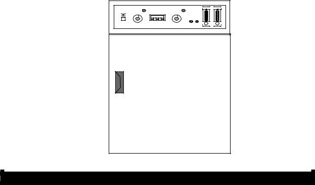
Incoming gas mixture passes through the rear plenum and is gently circulated throughout the chamber. Adjustable flow meters control air and CO2 concentrations. An access port on the control panel permits chamber gas samples to be taken.
A microprocessor-based controller maintains temperature while a hydraulic thermostat provides over-temperature protection to the chamber in the event the main control should fail.
Heaters outside the chamber inner walls are positioned for uniform heat distribution, while high-density fiberglass insulation minimizes heat loss. A fan in the chamber ceiling gently circulates chamber atmosphere to prevent temperature and CO2 stratification.
A double-door system enables unobstructed viewing of the entire chamber. In the steel outer door are heaters that can be turned on to defog the glass inner door, if necessary. Heat control for the steel outer door is on the back panel.
The leak proof chamber is constructed of heavy-gauge stainless steel and the steel cabinet has a powder coated finish for easy cleaning. Stainless steel shelves are adjustable and removable.
Differences between models in this series are the number of incubation chambers (one or two), and power requirements.
MODEL 320:
SECTION 3
SPECIFICATIONS
POWER REQUIREMENTS: |
120 V |
60 Hz |
6.3 |
Amps |
750 |
Watts |
320: |
||||||
320-1: |
230/240 V |
50 Hz |
3.1 |
Amps |
750 Watts |
|
322: |
120 V |
60 Hz |
12.5 |
Amps |
1500 |
Watts |
322-1: |
230/240 V |
50 Hz |
6.3 |
Amps |
1500 |
Watts |
325: |
120 V |
60 Hz |
12.5 |
Amps |
1500 |
Watts |
325-1: |
230/240 V |
50 Hz |
6.3 |
Amps |
1500 |
Watts |
8

TEMPERATURE |
From slightly above ambient to 60ºC |
|
||
Range: |
|
|||
HUMIDITY RANGE: |
From ambient to 98% relative humidity. |
|||
CARBON DIOXIDE RANGE: |
From 0 to 20% of the mixture. |
|
||
DIMENSIONS |
OVERALL |
|
CHAMBER |
|
320, 320-1 |
|
|||
24-5/8"W x 25"D x 33"H |
22"W x 22"D x 22"H |
|||
SINGLE: |
(63 x 64 x 84 cm) |
(56 x 56 x 56 cm) |
||
322, 322-1 |
49¼"W x 25"D x 33"H |
22"W x 22"D x 22"H |
||
DUAL, HORIZONTAL: |
(125 x 63 x 84 cm) |
(56 x 56 x 56 cm) |
||
325, 325-1 |
24-5/8"W x 25"D x 66"H |
22"W x 22"D x 22"H |
||
DUAL, VERTICAL: |
(63 x 64 x 168 cm) |
(56 x 56 x 56 cm) |
||
320, 320-1: |
VOLUME |
SHELVES* SHELF AREA |
||
6.2 cu. ft. |
5 |
13.4 |
sq. ft. |
|
322, 322-1: |
12.4 cu. ft. |
10 |
26.8 |
sq. ft. |
325, 325-1: |
12.4 cu. ft. |
10 |
26.8 |
sq. ft. |
*A MAXIMUM OF 10 SHELVES IN SINGLE UNIT AND 20 SHELVES IN DUAL UNITS CAN BE USED.
UNIT’S ENVIRONMENTAL OPERATING CONDITIONS:
POLLUTION DEGREE: 2
INSTALLATION CATEGORY: II
ALTITUDE: 2000 Meters MSL (Mean Sea Level) HUMIDITY: 80% maximum, non-condensing
ELECTRICAL SUPPLY: 120VAC or 240VAC
VOLTAGE TOLERANCE: ±10% of normal rated line
TEMPERATURE: 15ºC to 40ºC
PRODUCT USAGE: This product is intended for use indoors only
SECTION 4
INSTALLATION
√ SHIPPING CARTON:
This should be inspected upon delivery. When received, carefully examine for any shipping damage before unpacking. If damage is discovered, the delivering carrier should both specify and sign for the damage on your copy of the delivery receipt.
Open the carton carefully making certain that all parts are accounted for before packaging materials are discarded—after unpacking, if damage is found, promptly report it to the carrier and request a damage inspection promptly.
9
IMPORTANT: Failure to request an inspection of damage within a few days after receipt of shipment absolves the carrier from any liability for damage: you must call for a damage inspection promptly.
DANGER: DO NOT USE IN THE PRESENCE OF FLAMMABLE OR COMBUSTIBLE MATERIALS OR EXPLOSIVE GASES. DO NOT USE IN THE PRESENCE OF PRESSURIZED OR SEALED CONTAINERS—FIRE OR EXPLOSION MAY RESULT, CAUSING DEATH OR SEVERE INJURY.
WARNING: DO NOT HEAT ANY SUBSTANCE ABOVE A TEMPERATURE THAT WILL CAUSE IT TO EMIT TOXIC FUMES—DEATH OR SEVERE INJURY MAY RESULT.
CAUTION: THIS UNIT IS DESIGNED FOR USE WITH GASEOUS AIR, CO2 OR NITROGEN ONLY. DO NOT USE WITH ANY OTHER GASES. FAILURE TO OBSERVE THESE PRECAUTIONS CAN RESULT IN EXPLOSION AND/OR FIRE AND SERIOUS INJURY AND/OR DEATH AND PROPERTY DAMAGE.
LOCATION:
Place the unit where it will be used, away from external vibration sources, drafts and wide variations in ambient temperature. Choose a location near a power supply that matches the unit nameplate requirements.
ELECTRICAL CONNECTION:
120 VAC models require a 120 VAC, 50/60 Hz power source. They are supplied with a 3-wire line cord. It should be plugged into an outlet designed for 3-prong plugs. If an extension cord is used, it also should be the 3-wire grounded type. For an outlet designed to accept 2-prong plugs (ungrounded), it is required that a qualified electrician replaces the outlet with a new, grounded type.
240 VAC models require a 240 VAC, 50/60 Hz power source. Because of the variety of plug configurations in use worldwide for 240 VAC power, the unit is furnished with the plug removed. The user must install a plug to conform to local code and configuration requirements.
If a plug must be installed, use only the 3-prong grounded type, rated for the unit load requirements and matching the power outlet. Make sure the green ground wire is secured to the plug ground terminal.
NOTE: LEAVE UNIT DISCONNECTED WHEN NOT IN USE.
INSTALLATION: (Con’t)
HUMIDIFICATION:
To raise the humidity level in the chamber above ambient, add water to the humidity pan in the chamber.
AIR/CO2 HOOK-UPS:
Turn the power switch to OFF and insert the plug into the outlet.
TO AIR FITTING |
1/4” HOSE BARB |
10
CONNECTIONS
TO CO2 FITTING
SET PRESSURE AT 10 PSI.
PRESSURE REGULATORS AND GAUGES MUST
BE INSTALLED ON EACH TANK. CHECK LOCAL
GAS SUPPLIER FOR PROPER REGULATORS.
IF AIR PUMP IS USED INSTEAD OF TANK,
AIR MUST BE FILTERED TO REMOVE WATER,
OIL AND DIRT.
100% AIR |
100% CO2 |
Turn all flow meters on the incubator fully clockwise (closed). Connect air and CO2 supply lines to their respective fittings on the back of the unit. Use 1/4" ID tubing, flexible metal hose, etc., (meeting local codes), with filters to insure that the air and CO2 are free of contaminants, for gas lines.
Set the supply regulators at 10 psi. Check all of the connections for leaks.
NOTE: FOR DUAL CHAMBER MODELS, EACH CHAMBER HAS A SEPARATE SET OF AIR AND GAS FITTINGS.
WARNING: HIGH CONCENTRATIONS OF CARBON DIOXIDE PRODUCE METABOLIC ABNORMALITIES, DISTURBANCES OF THE CENTRAL NERVOUS SYSTEM AND CARDIAC INSTABILITY. UNCONSCIOUSNESS MAY OCCUR AT CONCENTRATIONS ABOVE 10%.
INSTALLATION: (Con’t)
SHELVING/PLENUM INSTALLATION-SELF-SUPPORTING SYSTEM COMPONENTS:
|
|
TOP PLENUM |
|
SHELF SUPPORT SIDE PANELS |
||||
|
|
|
|
|
|
|
|
|
|
|
|
|
|
|
|
|
|
|
|
|
|
|
|
|
|
|
|
|
|
|
|
|
|
|
|
|
|
|
|
|
|
|
|
|
|
|
|
|
|
|
|
|
|
|
|
|
|
|
|
|
|
|
|
|
|
|
|
|
|
|
|
|
|
|
|
|
|
|
|
|
|
|
|
|
|
|
|
|
|
|
|
|
|
|
|
|
|
|
|
|
|
|
|
|
|
|
|
|
|
|
|
|
|
|
|
|
|
|
|
|
|
|
|
|
|
|
|
|
|
|
|
|
|
|
|
|
|
|
|
|
|
|
|
|
|
|
|
|
|
|
|
|
|
|
|
|
|
|
|
|
|
11
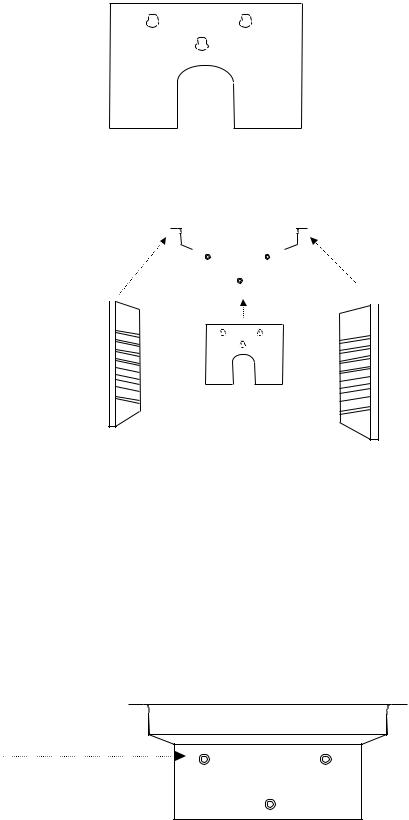
REAR COVER PANEL
SHELVING/PLENUM INSTALLATION-SELF-SUPPORTING SYSTEM ASSEMBLED
TOP PLENUM
SHELF SUPPORT |
|
|
|
|
|
|
|
SHELF SUPPORT |
|
|
|
|
|
|
|
||
|
|
|
|
|
|
|
||
|
|
|
|
|
|
|
||
|
|
|
|
|
|
|
||
SIDE PANEL |
|
|
|
|
|
|
|
SIDE PANEL |
|
||||||||
|
|
|
|
|
|
|
REAR COVER PANEL
INSTALLATION: (Con’t)
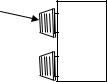
SHELVING AND PLENUM INSTALLATION-4 STEPS:
NOTE: NO TOOLS OR FASTENERS ARE REQUIRED. THE COMPONENTS FIT TOGETHER INTO A SELF-SUPPORTING ASSEMBLY.
TOP PLENUM, HEAD-ON VIEW:
KEYWAY STUDS
(ONTO WHICH THE CHAMBER’S REAR COVER PANEL KEYHOLE SLOTS WILL FIT)
12
 Loading...